Embed Size (px)
Citation preview
深圳市天工测控技术有限公司 SKG13BL-Datasheet
SKG13BL-DA-001,A/2
1
GPS Module Datasheet
Name: Ultra High Sensitivity and Low Power GPS Receiver Module
Model No.: SKG13BL
Revision: V3.01
Revision History: Revision Description Approved Date
V1.01 Initial Release to V1.01 George 20120703 V2.01 Update office’s address George 20131119 V3.01 Change the pin definition George 20140227
深圳市天工测控技术有限公司 SKG13BL-Datasheet
SKG13BL-DA-001,A/2
2
General Description
The SKG13BL is a complete GPS engine module that features super sensitivity, ultra low power and small form factor. The GPS signal is applied to the antenna input of module, and a complete serial data message with position, velocity and time information is presented at the serial interface with NMEA protocol or custom protocol.
It is based on the high performance features of the MediaTek MT3337 single-chip architecture, Its –165dBm tracking sensitivity extends positioning coverage into place like urban canyons and dense foliage environment where the GPS was not possible before. The small form factor and low power consumption make the module easy to integrate into portable device like PNDs, mobile phones, cameras and vehicle navigation systems.
Applications
LBS (Location Based Service) PND (Portable Navigation Device) Vehicle navigation system Mobile phone
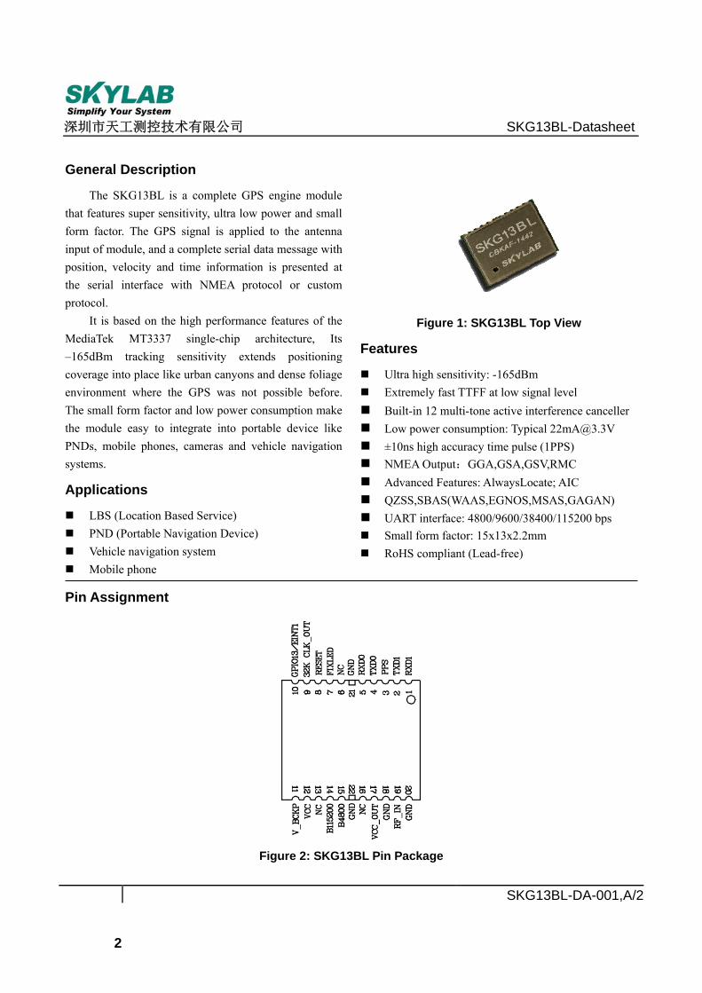
Figure 1: SKG13BL Top View
Features
Ultra high sensitivity: -165dBm Extremely fast TTFF at low signal level Built-in 12 multi-tone active interference canceller Low power consumption: Typical [email protected] ±10ns high accuracy time pulse (1PPS) NMEA Output:GGA,GSA,GSV,RMC Advanced Features: AlwaysLocate; AIC QZSS,SBAS(WAAS,EGNOS,MSAS,GAGAN) UART interface: 4800/9600/38400/115200 bps Small form factor: 15x13x2.2mm RoHS compliant (Lead-free)
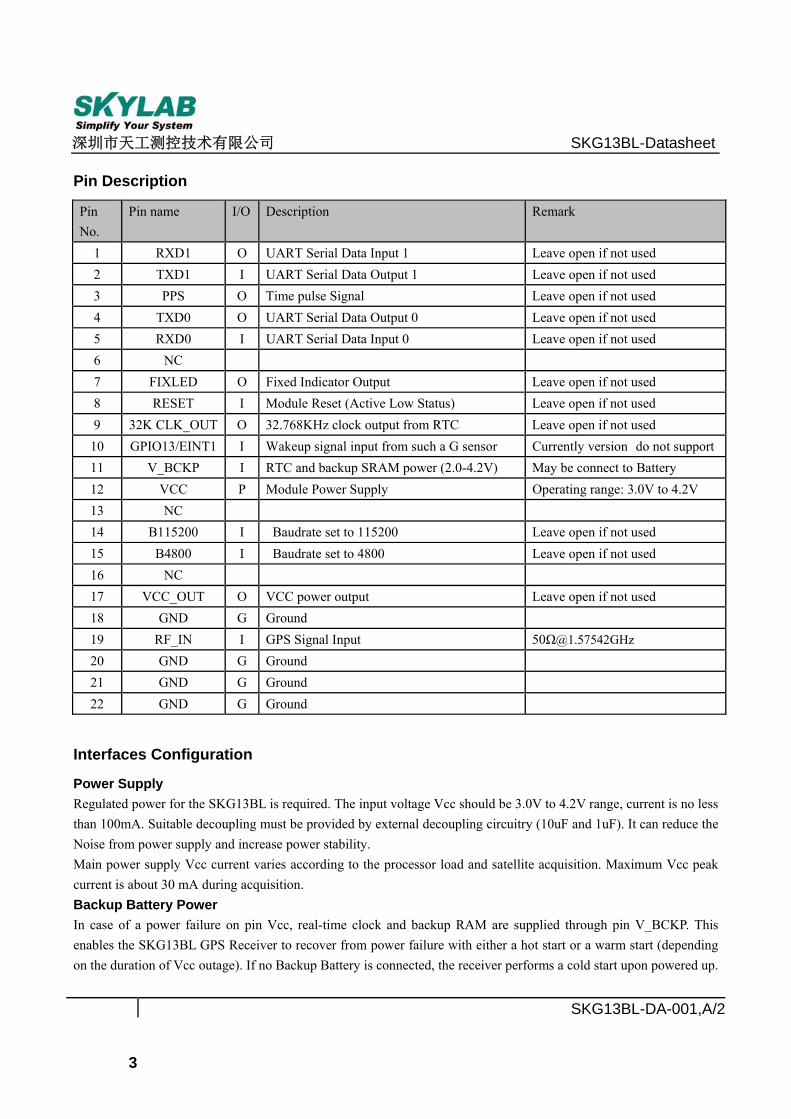
Pin Assignment
Figure 2: SKG13BL Pin Package
深圳市天工测控技术有限公司 SKG13BL-Datasheet
SKG13BL-DA-001,A/2
3
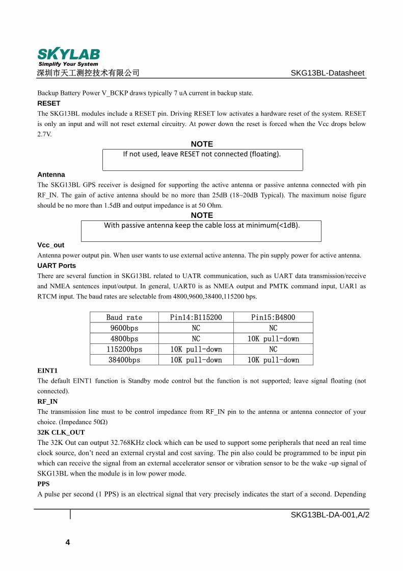
Pin Description
Pin No.
Pin name I/O Description Remark
1 RXD1 O UART Serial Data Input 1 Leave open if not used 2 TXD1 I UART Serial Data Output 1 Leave open if not used 3 PPS O Time pulse Signal Leave open if not used 4 TXD0 O UART Serial Data Output 0 Leave open if not used 5 RXD0 I UART Serial Data Input 0 Leave open if not used 6 NC 7 FIXLED O Fixed Indicator Output Leave open if not used 8 RESET I Module Reset (Active Low Status) Leave open if not used 9 32K CLK_OUT O 32.768KHz clock output from RTC Leave open if not used
10 GPIO13/EINT1 I Wakeup signal input from such a G sensor Currently version do not support11 V_BCKP I RTC and backup SRAM power (2.0-4.2V) May be connect to Battery 12 VCC P Module Power Supply Operating range: 3.0V to 4.2V 13 NC 14 B115200 I Baudrate set to 115200 Leave open if not used 15 B4800 I Baudrate set to 4800 Leave open if not used 16 NC 17 VCC_OUT O VCC power output Leave open if not used 18 GND G Ground 19 RF_IN I GPS Signal Input 50Ω@1.57542GHz 20 GND G Ground 21 GND G Ground 22 GND G Ground
Interfaces Configuration
Power Supply Regulated power for the SKG13BL is required. The input voltage Vcc should be 3.0V to 4.2V range, current is no less than 100mA. Suitable decoupling must be provided by external decoupling circuitry (10uF and 1uF). It can reduce the Noise from power supply and increase power stability. Main power supply Vcc current varies according to the processor load and satellite acquisition. Maximum Vcc peak current is about 30 mA during acquisition. Backup Battery Power In case of a power failure on pin Vcc, real-time clock and backup RAM are supplied through pin V_BCKP. This enables the SKG13BL GPS Receiver to recover from power failure with either a hot start or a warm start (depending on the duration of Vcc outage). If no Backup Battery is connected, the receiver performs a cold start upon powered up.
深圳市天工测控技术有限公司 SKG13BL-Datasheet
SKG13BL-DA-001,A/2
4
Backup Battery Power V_BCKP draws typically 7 uA current in backup state. RESET The SKG13BL modules include a RESET pin. Driving RESET low activates a hardware reset of the system. RESET is only an input and will not reset external circuitry. At power down the reset is forced when the Vcc drops below 2.7V.
NOTE If not used, leave RESET not connected (floating).
Antenna The SKG13BL GPS receiver is designed for supporting the active antenna or passive antenna connected with pin RF_IN. The gain of active antenna should be no more than 25dB (18~20dB Typical). The maximum noise figure should be no more than 1.5dB and output impedance is at 50 Ohm.
NOTE With passive antenna keep the cable loss at minimum(<1dB).
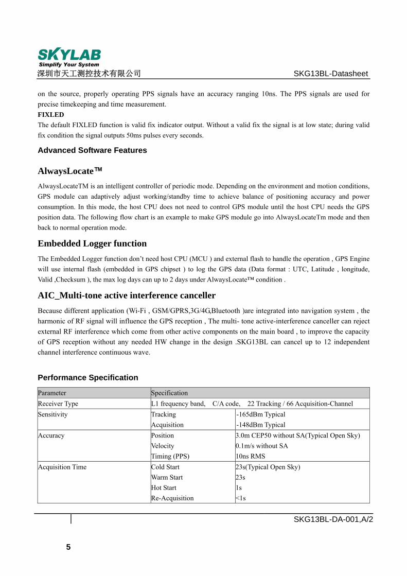
Vcc_out Antenna power output pin. When user wants to use external active antenna. The pin supply power for active antenna. UART Ports There are several function in SKG13BL related to UATR communication, such as UART data transmission/receive and NMEA sentences input/output. In general, UART0 is as NMEA output and PMTK command input, UAR1 as RTCM input. The baud rates are selectable from 4800,9600,38400,115200 bps.
Baud rate Pin14:B115200 Pin15:B4800
9600bps NC NC
4800bps NC 10K pull-down
115200bps 10K pull-down NC
38400bps 10K pull-down 10K pull-down
EINT1 The default EINT1 function is Standby mode control but the function is not supported; leave signal floating (not connected). RF_IN The transmission line must to be control impedance from RF_IN pin to the antenna or antenna connector of your choice. (Impedance 50Ω) 32K CLK_OUT The 32K Out can output 32.768KHz clock which can be used to support some peripherals that need an real time clock source, don’t need an external crystal and cost saving. The pin also could be programmed to be input pin which can receive the signal from an external accelerator sensor or vibration sensor to be the wake -up signal of SKG13BL when the module is in low power mode. PPS A pulse per second (1 PPS) is an electrical signal that very precisely indicates the start of a second. Depending
深圳市天工测控技术有限公司 SKG13BL-Datasheet
SKG13BL-DA-001,A/2
5
on the source, properly operating PPS signals have an accuracy ranging 10ns. The PPS signals are used for precise timekeeping and time measurement. FIXLED The default FIXLED function is valid fix indicator output. Without a valid fix the signal is at low state; during valid fix condition the signal outputs 50ms pulses every seconds.
Advanced Software Features
AlwaysLocate™ AlwaysLocateTM is an intelligent controller of periodic mode. Depending on the environment and motion conditions, GPS module can adaptively adjust working/standby time to achieve balance of positioning accuracy and power consumption. In this mode, the host CPU does not need to control GPS module until the host CPU needs the GPS position data. The following flow chart is an example to make GPS module go into AlwaysLocateTm mode and then back to normal operation mode.
Embedded Logger function The Embedded Logger function don’t need host CPU (MCU ) and external flash to handle the operation , GPS Engine will use internal flash (embedded in GPS chipset ) to log the GPS data (Data format : UTC, Latitude , longitude, Valid ,Checksum ), the max log days can up to 2 days under AlwaysLocate™ condition .
AIC_Multi-tone active interference canceller Because different application (Wi-Fi , GSM/GPRS,3G/4G,Bluetooth )are integrated into navigation system , the harmonic of RF signal will influence the GPS reception , The multi- tone active-interference canceller can reject external RF interference which come from other active components on the main board , to improve the capacity of GPS reception without any needed HW change in the design .SKG13BL can cancel up to 12 independent channel interference continuous wave.
Performance Specification
Parameter Specification Receiver Type L1 frequency band, C/A code, 22 Tracking / 66 Acquisition-Channel Sensitivity Tracking
Acquisition -165dBm Typical -148dBm Typical
Accuracy
Position Velocity Timing (PPS)
3.0m CEP50 without SA(Typical Open Sky) 0.1m/s without SA 10ns RMS
Acquisition Time Cold Start Warm Start Hot Start Re-Acquisition
23s(Typical Open Sky) 23s 1s <1s
深圳市天工测控技术有限公司 SKG13BL-Datasheet
SKG13BL-DA-001,A/2
6
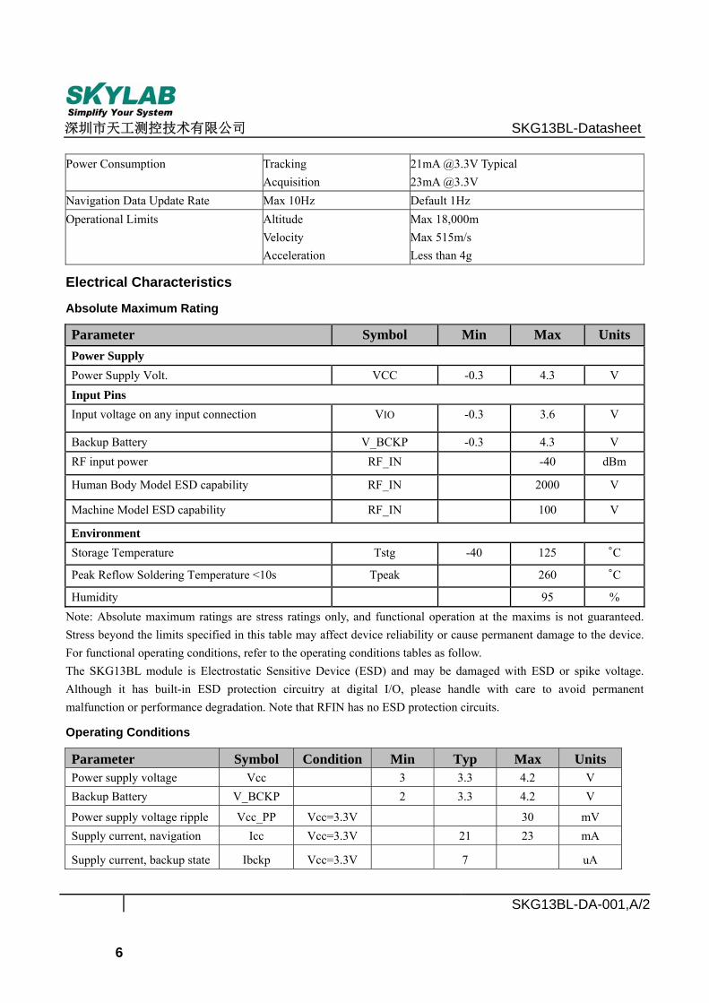
Power Consumption Tracking Acquisition
21mA @3.3V Typical 23mA @3.3V
Navigation Data Update Rate Max 10Hz Default 1Hz Operational Limits Altitude
Velocity Acceleration
Max 18,000m Max 515m/s Less than 4g
Electrical Characteristics
Absolute Maximum Rating
Parameter Symbol Min Max Units Power Supply Power Supply Volt. VCC -0.3 4.3 V Input Pins Input voltage on any input connection VIO -0.3 3.6 V
Backup Battery V_BCKP -0.3 4.3 V RF input power RF_IN -40 dBm
Human Body Model ESD capability RF_IN 2000 V
Machine Model ESD capability RF_IN 100 V
Environment Storage Temperature Tstg -40 125 °C
Peak Reflow Soldering Temperature <10s Tpeak 260 °C
Humidity 95 % Note: Absolute maximum ratings are stress ratings only, and functional operation at the maxims is not guaranteed. Stress beyond the limits specified in this table may affect device reliability or cause permanent damage to the device. For functional operating conditions, refer to the operating conditions tables as follow. The SKG13BL module is Electrostatic Sensitive Device (ESD) and may be damaged with ESD or spike voltage. Although it has built-in ESD protection circuitry at digital I/O, please handle with care to avoid permanent malfunction or performance degradation. Note that RFIN has no ESD protection circuits.
Operating Conditions
Parameter Symbol Condition Min Typ Max Units Power supply voltage Vcc 3 3.3 4.2 V Backup Battery V_BCKP 2 3.3 4.2 V
Power supply voltage ripple Vcc_PP Vcc=3.3V 30 mV Supply current, navigation Icc Vcc=3.3V 21 23 mA
Supply current, backup state Ibckp Vcc=3.3V 7 uA
深圳市天工测控技术有限公司 SKG13BL-Datasheet
SKG13BL-DA-001,A/2
7
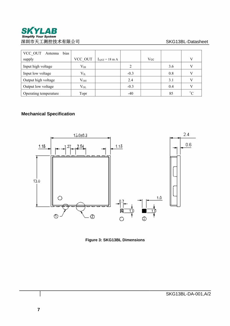
VCC_OUT Antenna bias supply VCC_OUT IANT = 18 m A Vcc V
Input high voltage VIH 2 3.6 V
Input low voltage VIL -0.3 0.8 V
Output high voltage VOH 2.4 3.1 V Output low voltage VOL -0.3 0.4 V
Operating temperature Topr -40 85 °C
Mechanical Specification
Figure 3: SKG13BL Dimensions
深圳市天工测控技术有限公司 SKG13BL-Datasheet
SKG13BL-DA-001,A/2
8
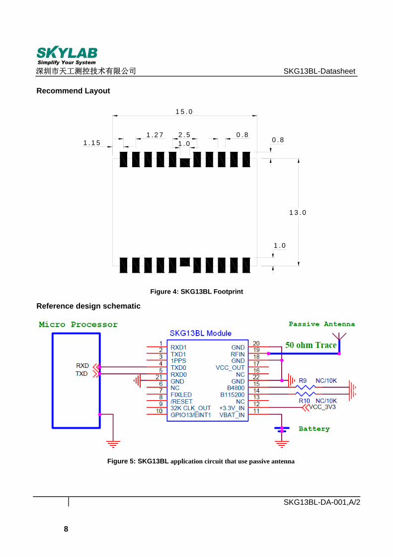
Recommend Layout
1.0
0.8
13.0
1.151.27 2.5
1.0
15.0
0.8
Figure 4: SKG13BL Footprint
Reference design schematic
Figure 5: SKG13BL application circuit that use passive antenna
深圳市天工测控技术有限公司 SKG13BL-Datasheet
SKG13BL-DA-001,A/2
9
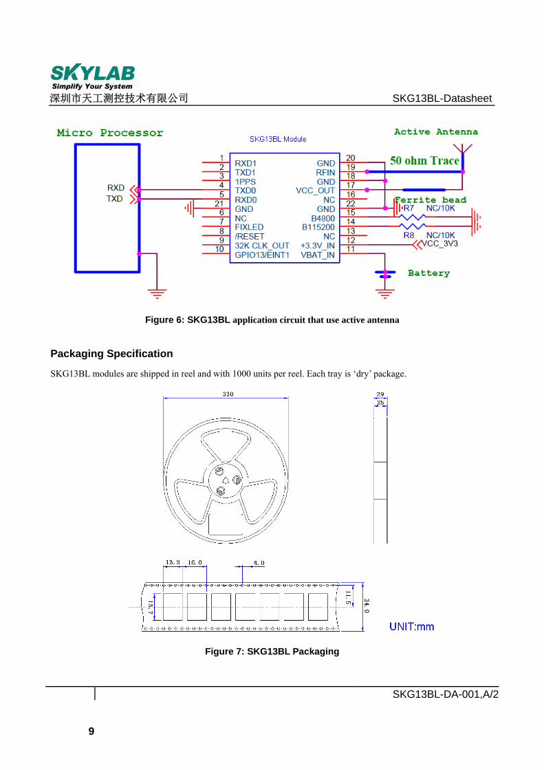
Figure 6: SKG13BL application circuit that use active antenna
Packaging Specification
SKG13BL modules are shipped in reel and with 1000 units per reel. Each tray is ‘dry’ package.
Figure 7: SKG13BL Packaging
深圳市天工测控技术有限公司 SKG13BL-Datasheet
SKG13BL-DA-001,A/2
10
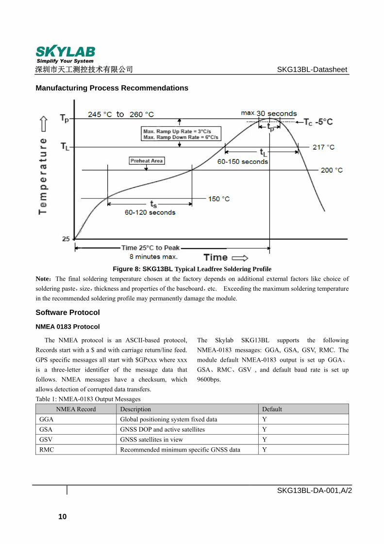
Manufacturing Process Recommendations
Figure 8: SKG13BL Typical Leadfree Soldering Profile
Note:The final soldering temperature chosen at the factory depends on additional external factors like choice of soldering paste,size,thickness and properties of the baseboard,etc. Exceeding the maximum soldering temperature in the recommended soldering profile may permanently damage the module.
Software Protocol
NMEA 0183 Protocol
The NMEA protocol is an ASCII-based protocol, Records start with a $ and with carriage return/line feed. GPS specific messages all start with $GPxxx where xxx is a three-letter identifier of the message data that follows. NMEA messages have a checksum, which allows detection of corrupted data transfers.
The Skylab SKG13BL supports the following NMEA-0183 messages: GGA, GSA, GSV, RMC. The module default NMEA-0183 output is set up GGA、
GSA、RMC、GSV , and default baud rate is set up 9600bps.
Table 1: NMEA-0183 Output Messages NMEA Record Description Default
GGA Global positioning system fixed data Y GSA GNSS DOP and active satellites Y GSV GNSS satellites in view Y RMC Recommended minimum specific GNSS data Y
深圳市天工测控技术有限公司 SKG13BL-Datasheet
SKG13BL-DA-001,A/2
11
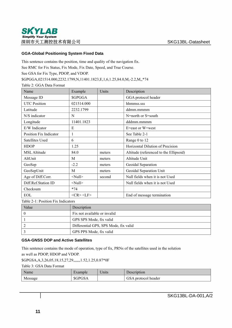
GGA-Global Positioning System Fixed Data
This sentence contains the position, time and quality of the navigation fix. See RMC for Fix Status, Fix Mode, Fix Date, Speed, and True Course. See GSA for Fix Type, PDOP, and VDOP. $GPGGA,021514.000,2232.1799,N,11401.1823,E,1,6,1.25,84.0,M,-2.2,M,,*74 Table 2: GGA Data Format
Name Example Units Description Message ID $GPGGA GGA protocol header UTC Position 021514.000 hhmmss.sss Latitude 2232.1799 ddmm.mmmm N/S indicator N N=north or S=south Longitude 11401.1823 dddmm.mmmm E/W Indicator E E=east or W=west Position Fix Indicator 1 See Table 2-1 Satellites Used 6 Range 0 to 12 HDOP 1.25 Horizontal Dilution of Precision MSL Altitude 84.0 meters Altitude (referenced to the Ellipsoid) AltUnit M meters Altitude Unit GeoSep -2.2 meters Geoidal Separation GeoSepUnit M meters Geoidal Separation Unit Age of Diff.Corr. <Null> second Null fields when it is not Used Diff.Ref.Station ID <Null> Null fields when it is not Used Checksum *74 EOL <CR> <LF> End of message termination
Table 2-1: Position Fix Indicators Value Description 0 Fix not available or invalid 1 GPS SPS Mode, fix valid 2 Differential GPS, SPS Mode, fix valid 3 GPS PPS Mode, fix valid
GSA-GNSS DOP and Active Satellites
This sentence contains the mode of operation, type of fix, PRNs of the satellites used in the solution as well as PDOP, HDOP and VDOP. $GPGSA,A,3,26,05,18,15,27,29,,,,,,,1.52,1.25,0.87*0F Table 3: GSA Data Format Name Example Units Description Message $GPGSA GSA protocol header
深圳市天工测控技术有限公司 SKG13BL-Datasheet
SKG13BL-DA-001,A/2
12
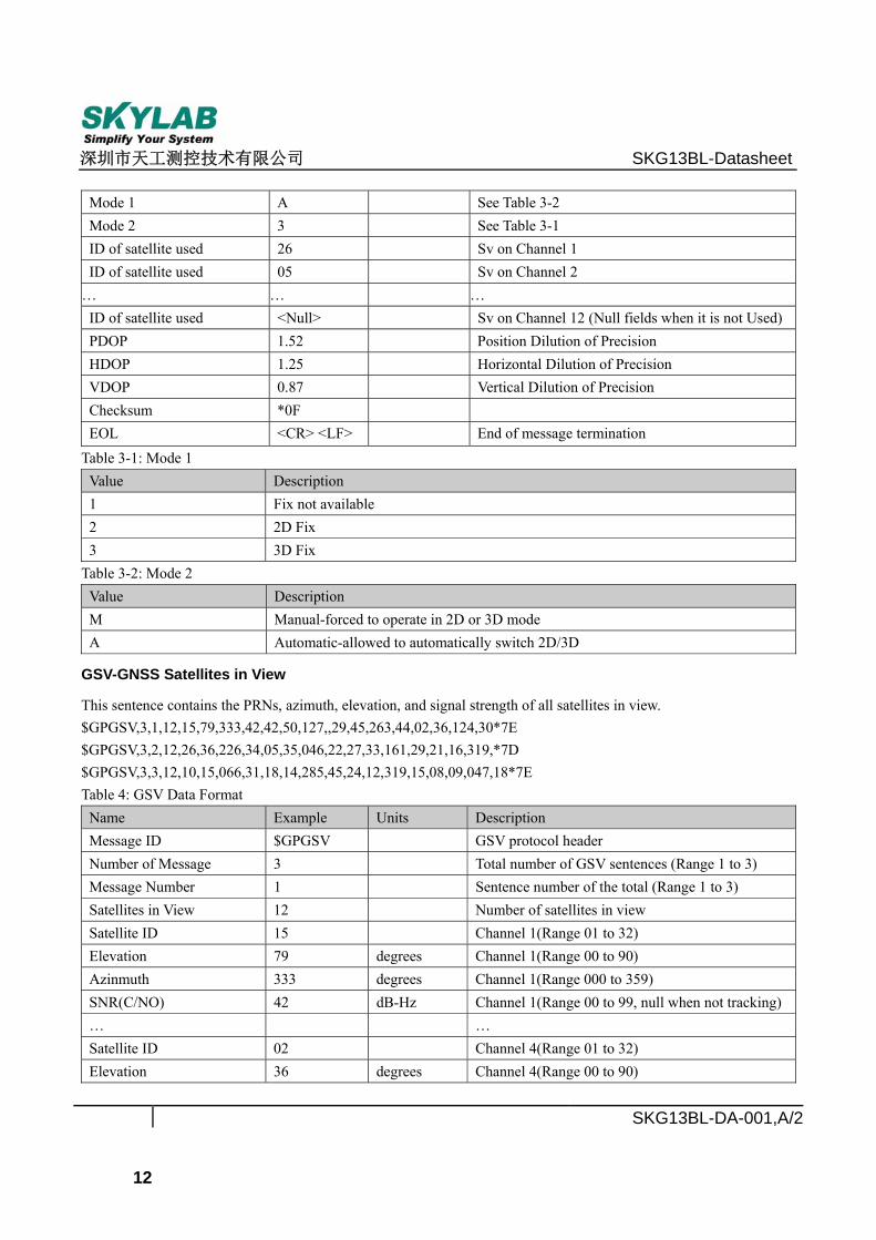
Mode 1 A See Table 3-2 Mode 2 3 See Table 3-1 ID of satellite used 26 Sv on Channel 1 ID of satellite used 05 Sv on Channel 2 … … … ID of satellite used <Null> Sv on Channel 12 (Null fields when it is not Used) PDOP 1.52 Position Dilution of Precision HDOP 1.25 Horizontal Dilution of Precision VDOP 0.87 Vertical Dilution of Precision Checksum *0F EOL <CR> <LF> End of message termination Table 3-1: Mode 1 Value Description 1 Fix not available 2 2D Fix 3 3D Fix Table 3-2: Mode 2 Value Description M Manual-forced to operate in 2D or 3D mode A Automatic-allowed to automatically switch 2D/3D
GSV-GNSS Satellites in View
This sentence contains the PRNs, azimuth, elevation, and signal strength of all satellites in view. $GPGSV,3,1,12,15,79,333,42,42,50,127,,29,45,263,44,02,36,124,30*7E $GPGSV,3,2,12,26,36,226,34,05,35,046,22,27,33,161,29,21,16,319,*7D $GPGSV,3,3,12,10,15,066,31,18,14,285,45,24,12,319,15,08,09,047,18*7E Table 4: GSV Data Format Name Example Units Description Message ID $GPGSV GSV protocol header Number of Message 3 Total number of GSV sentences (Range 1 to 3) Message Number 1 Sentence number of the total (Range 1 to 3) Satellites in View 12 Number of satellites in view Satellite ID 15 Channel 1(Range 01 to 32) Elevation 79 degrees Channel 1(Range 00 to 90) Azinmuth 333 degrees Channel 1(Range 000 to 359) SNR(C/NO) 42 dB-Hz Channel 1(Range 00 to 99, null when not tracking) … … Satellite ID 02 Channel 4(Range 01 to 32) Elevation 36 degrees Channel 4(Range 00 to 90)
深圳市天工测控技术有限公司 SKG13BL-Datasheet
SKG13BL-DA-001,A/2
13
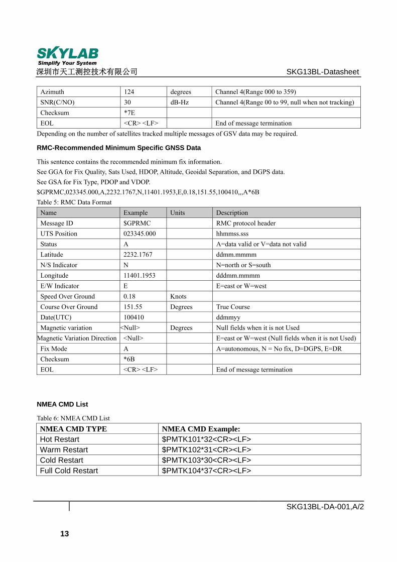
Azimuth 124 degrees Channel 4(Range 000 to 359) SNR(C/NO) 30 dB-Hz Channel 4(Range 00 to 99, null when not tracking) Checksum *7E EOL <CR> <LF> End of message termination Depending on the number of satellites tracked multiple messages of GSV data may be required.
RMC-Recommended Minimum Specific GNSS Data
This sentence contains the recommended minimum fix information. See GGA for Fix Quality, Sats Used, HDOP, Altitude, Geoidal Separation, and DGPS data. See GSA for Fix Type, PDOP and VDOP. $GPRMC,023345.000,A,2232.1767,N,11401.1953,E,0.18,151.55,100410,,,A*6B Table 5: RMC Data Format Name Example Units Description Message ID $GPRMC RMC protocol header UTS Position 023345.000 hhmmss.sss Status A A=data valid or V=data not valid Latitude 2232.1767 ddmm.mmmm N/S Indicator N N=north or S=south Longitude 11401.1953 dddmm.mmmm E/W Indicator E E=east or W=west Speed Over Ground 0.18 Knots Course Over Ground 151.55 Degrees True Course Date(UTC) 100410 ddmmyy Magnetic variation <Null> Degrees Null fields when it is not Used Magnetic Variation Direction <Null> E=east or W=west (Null fields when it is not Used) Fix Mode A A=autonomous, N = No fix, D=DGPS, E=DR Checksum *6B EOL <CR> <LF> End of message termination
NMEA CMD List
Table 6: NMEA CMD List NMEA CMD TYPE NMEA CMD Example: Hot Restart $PMTK101*32<CR><LF> Warm Restart $PMTK102*31<CR><LF> Cold Restart $PMTK103*30<CR><LF> Full Cold Restart $PMTK104*37<CR><LF>

深圳市天工测控技术有限公司 SKG13BL-Datasheet
SKG13BL-DA-001,A/2
14
Skylab M&C Technology Co., Ltd.
Address: 9th Floor, Zhongguang Building, Yayuan Road, Bantian, Shenzhen Phone: 86-755 8340 8210(Sales Support) Phone: 86-755 8340 8130(Technical Support) Fax: 86-755-8340 8560 E-Mail: [email protected] Website: www.skylab.com.cn