Embed Size (px)
DESCRIPTION
Collection of graduate and undergraduate projects. Updated for Spring 2016 with the latest projects from the Healthcare Design Facilities studio and the Collaboration studio.
Citation preview

PORTFOLIOJoshua FeltySpring 2016

Joshua Felty
3015 56th StreetLubbock, TX 79413
phone: 903-802-2487email: [email protected]
Houston Methodist Surgery Center
Dallas Holocaust Tolerance & Human Rights Museum
integrated architectural solutions: branch bank building
buildings: a technical understanding
urbanism: multi-use parking garage
site + program: community center
assemblies
1
11
21
27
31
33
35
Education
Texas Tech University College of ArchitectureMaster of Architecture
with Certificate in Healthcare Facilities Design
May 21, 2016
Texas Tech University College of Architecture
Bachelor of Science in ArchitectureMay 17, 2014
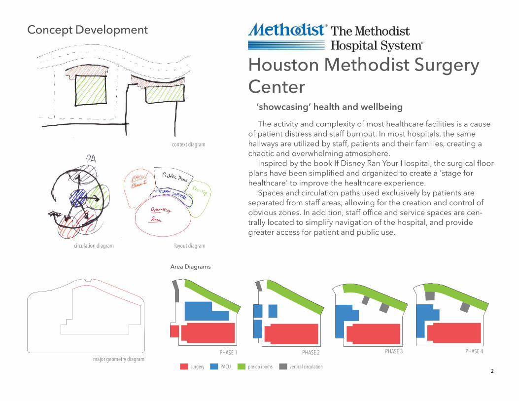
PACU pre-op roomssurgery vertical circulation
Area Diagrams
2
major geometry diagram
context diagram
PHASE 1 PHASE 2 PHASE 3 PHASE 4
circulation diagram layout diagram
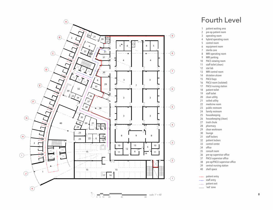
The activity and complexity of most healthcare facilities is a cause of patient distress and staff burnout. In most hospitals, the same hallways are utilized by staff, patients and their families, creating a chaotic and overwhelming atmosphere.
Inspired by the book If Disney Ran Your Hospital, the surgical floor plans have been simplified and organized to create a 'stage for healthcare' to improve the healthcare experience.
Spaces and circulation paths used exclusively by patients are separated from staff areas, allowing for the creation and control of obvious zones. In addition, staff office and service spaces are cen-trally located to simplify navigation of the hospital, and provide greater access for patient and public use.
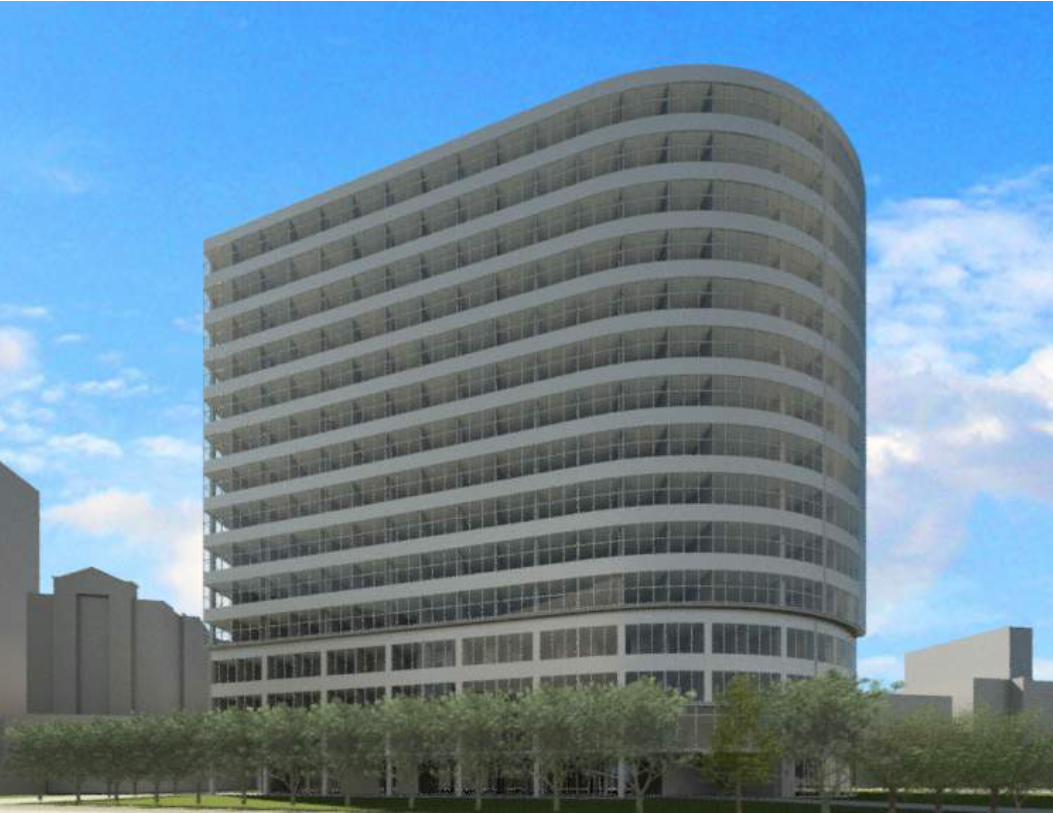
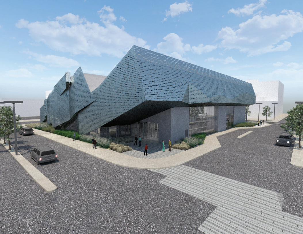
Houston Methodist Surgery Center
‘showcasing’ health and wellbeing
Concept Development
3
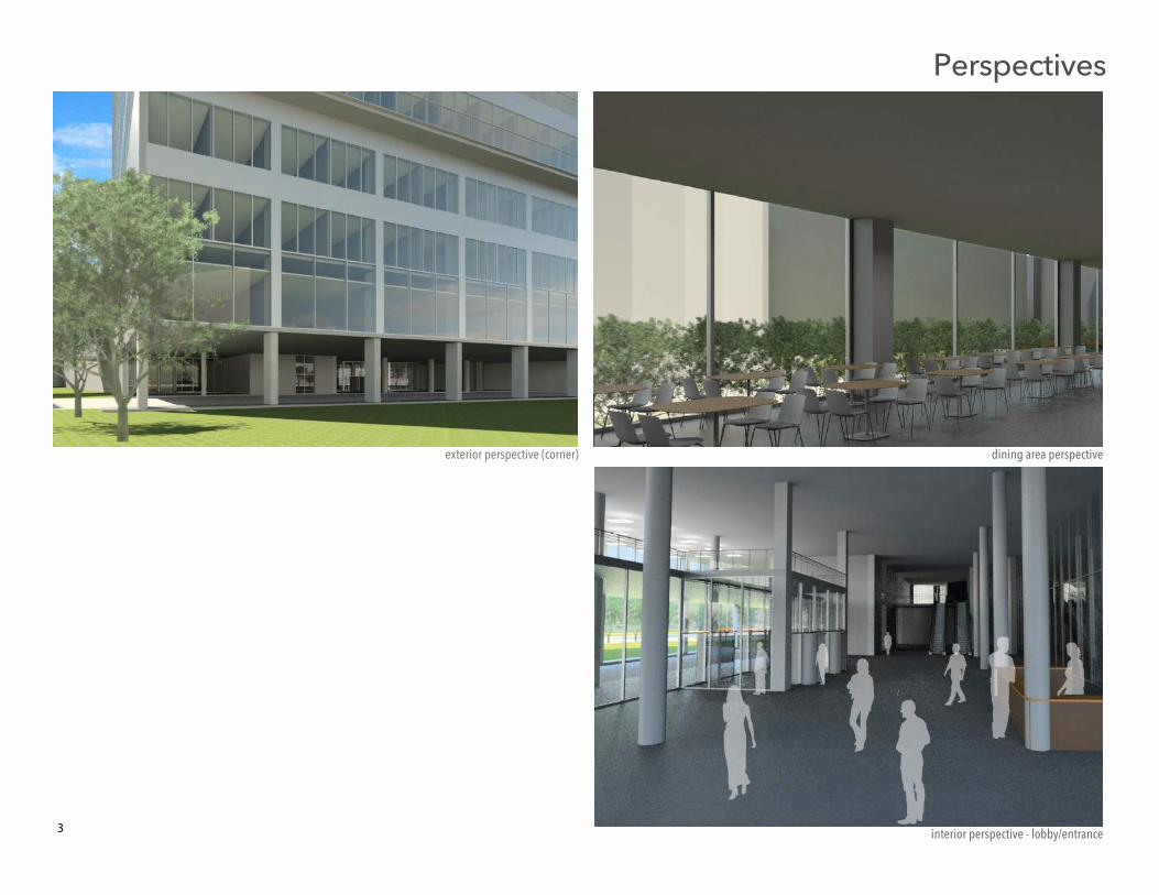
exterior perspective (corner)
interior perspective - lobby/entrance
dining area perspective
Perspectives
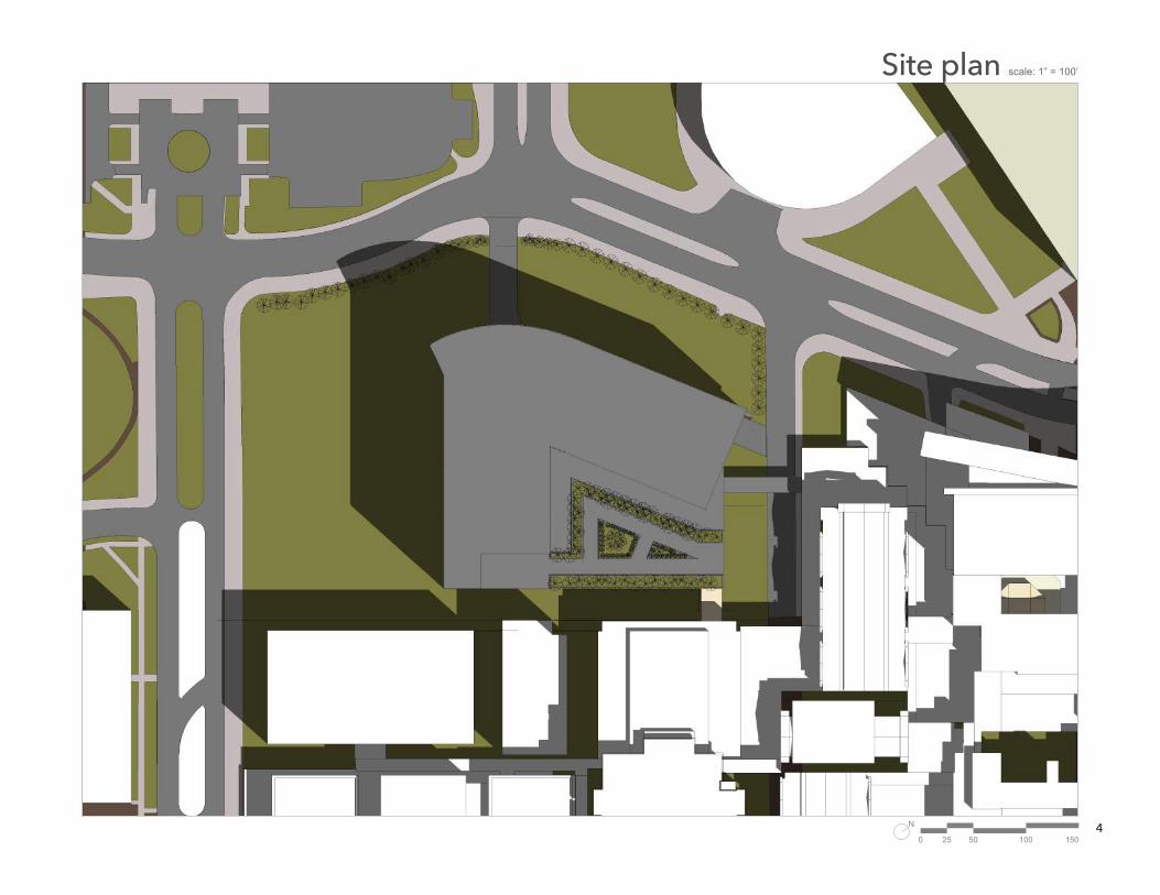
scale: 1” = 100’
4
Site plan
N
0 50 10025 150
UP
UP
A
B
C
D
E
F
G
H
I
J
K
1
2
3
4
5
6
7
8
9
11 11
11
8
9
10
7
6
512
13
14
1
4
2
153
5
123456789
10111213141516
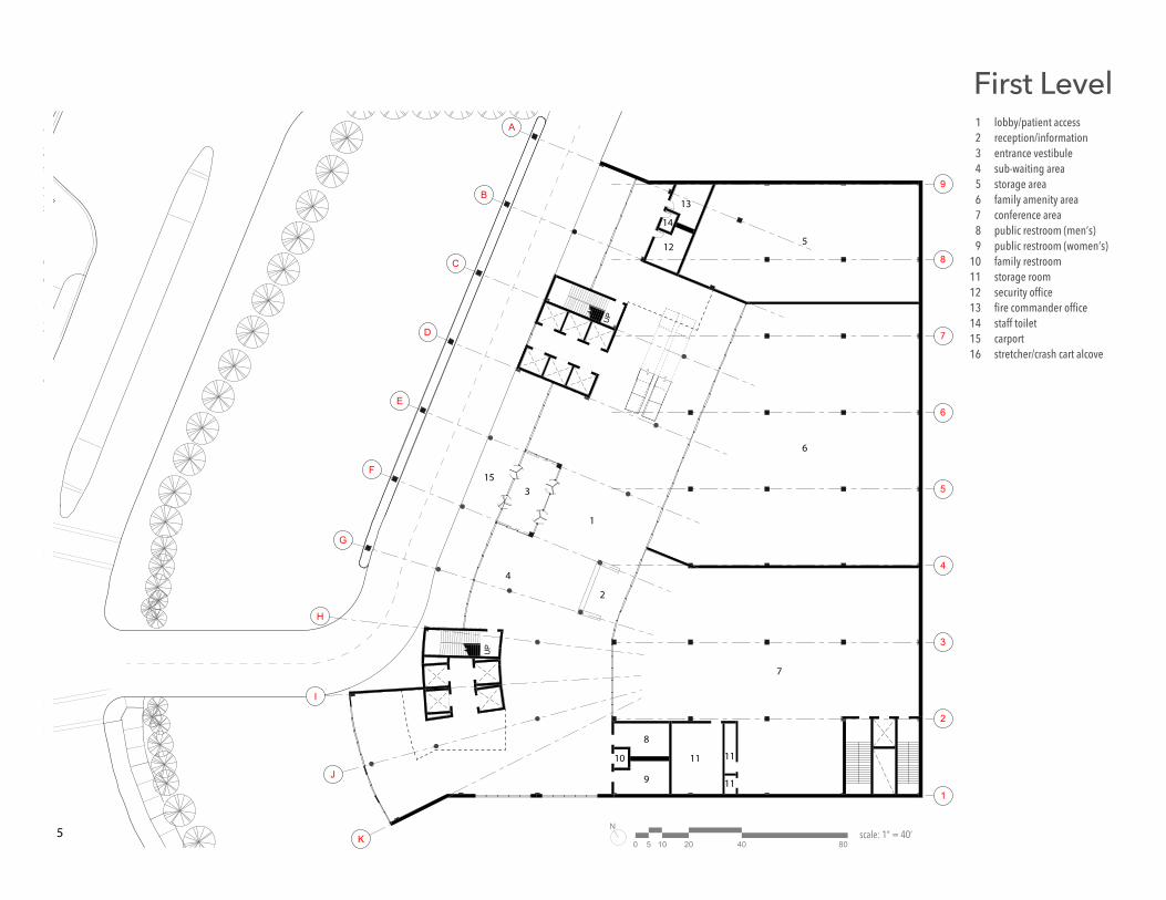
lobby/patient accessreception/informationentrance vestibulesub-waiting areastorage areafamily amenity areaconference areapublic restroom (men’s)public restroom (women’s)family restroomstorage roomsecurity officefire commander officestaff toiletcarportstretcher/crash cart alcove
First Level
0
N
105 20 40 80scale: 1” = 40’
2
3
4
1
DN
DN
A
B
C
D
E
F
G
H
I
J
6
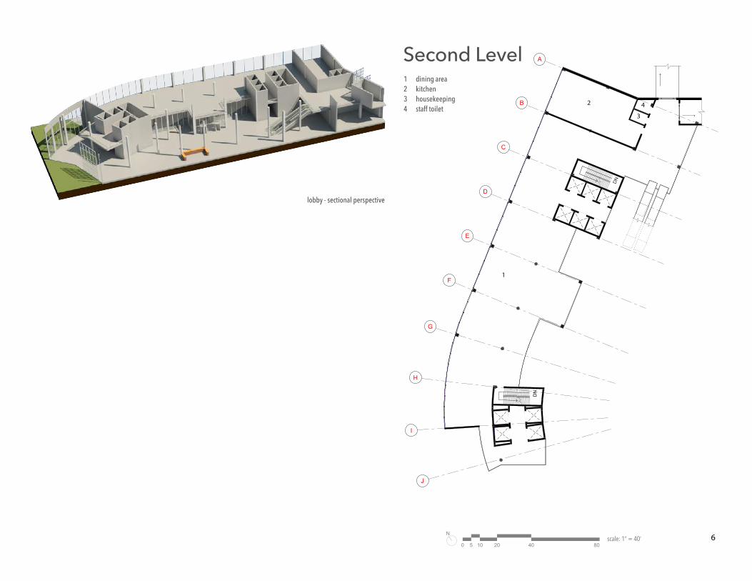
lobby - sectional perspective
1234
dining areakitchenhousekeepingstaff toilet
Second Level
0
N
105 20 40 80scale: 1” = 40’
A
B
C
D
E
F
G
H
I
J
K
1
2
3
4
5
6
7
8
92
2
14
1313
13
15
15
16
16
17
1717
17
26
27
28
3037
38
31
32
33
34
35
36
29
29
18
18
20
20
20
6
6
21
21
22
23
23
2524
19
19
1
3 3
33
33
44
6 565
5
7
8
9
12
10
11
10
11
6
7
123456789
1011121314151617181920212223242526272829303132333435363738
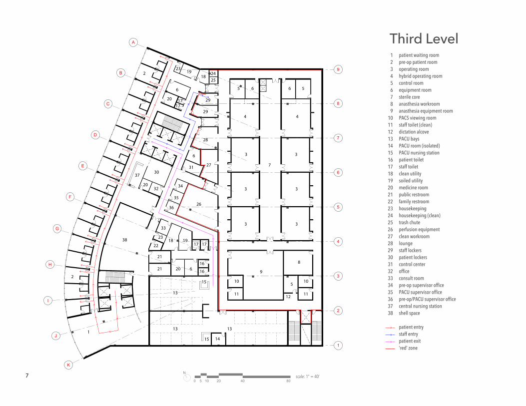
patient waiting roompre-op patient roomoperating roomhybrid operating roomcontrol roomequipment roomsterile coreanasthesia workroomanasthesia equipment roomPACS viewing roomstaff toilet (clean)dictation alcovePACU baysPACU room (isolated)PACU nursing stationpatient toiletstaff toiletclean utilitysoiled utilitymedicine roompublic restroomfamily restroomhousekeepinghousekeeping (clean)trash chuteperfusion equipmentclean workroomloungestaff lockerspatient lockerscontrol centerofficeconsult roompre-op supervisor officePACU supervisor officepre-op/PACU supervisor officecentral nursing stationshell space
patient entrystaff entrypatient exit‘red’ zone
Third Level
0
N
105 20 40 80scale: 1” = 40’
A
B
C
D
E
F
G
H
I
J
K
1
2
3
4
5
6
7
8
9
3 3
33
33
44
6 565
5
2
2
7
1617
17
18
18
19
26
27
28
29
30
31
3239
34
35
38
37
36
33
31
19
1919
21
21
2040
20
22
22
22
23
23
24
25
25
6
6
6
1515
15
1
898
126
14
1310
11
10
11
8
123456789
10111213141516171819202122232425262728293031323334353637383940
patient waiting areapre-op patient roomoperating roomhybrid operating roomcontrol roomequipment roomsterile coreMRI operating roomMRI parkingPACS viewing roomstaff toilet (clean)stat labMRI control roomdictation alcovePACU baysPACU room (isolated)PACU nursing stationpatient toiletstaff toiletclean utilitysoiled utilitymedicine roompublic restroomfamily restroomhousekeepinghousekeeping (clean)trash chutepharmacyclean workroomloungestaff lockerspatient lockerscontrol centerofficeconsult roompre-op supervisor officePACU supervisor officepre-op/PACU supervisor officecentral nursing stationshell space
patient entrystaff entrypatient exit‘red’ zone
Fourth Level
0
N
105 20 40 80scale: 1” = 40’
A
B
C
D
E
F
G
H
I
J
K
1
2
3
4
5
6
7
8
9
6
3
3
2
3 3
1
4
4
5
5
5
5
9
123456
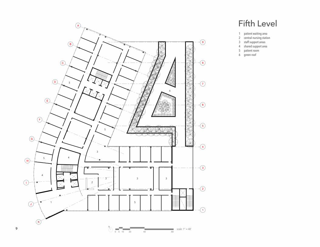
patient waiting areacentral nursing stationstaff support areasshared support areapatient roomgreen roof
Fifth Level
0
N
105 20 40 80scale: 1” = 40’
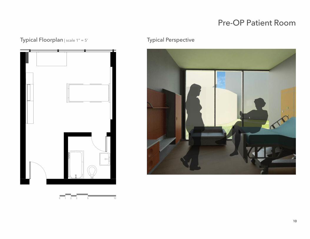
Typical Floorplan | scale 1” = 5’ Typical Perspective
10
Pre-OP Patient Room
0 21 3 5 10
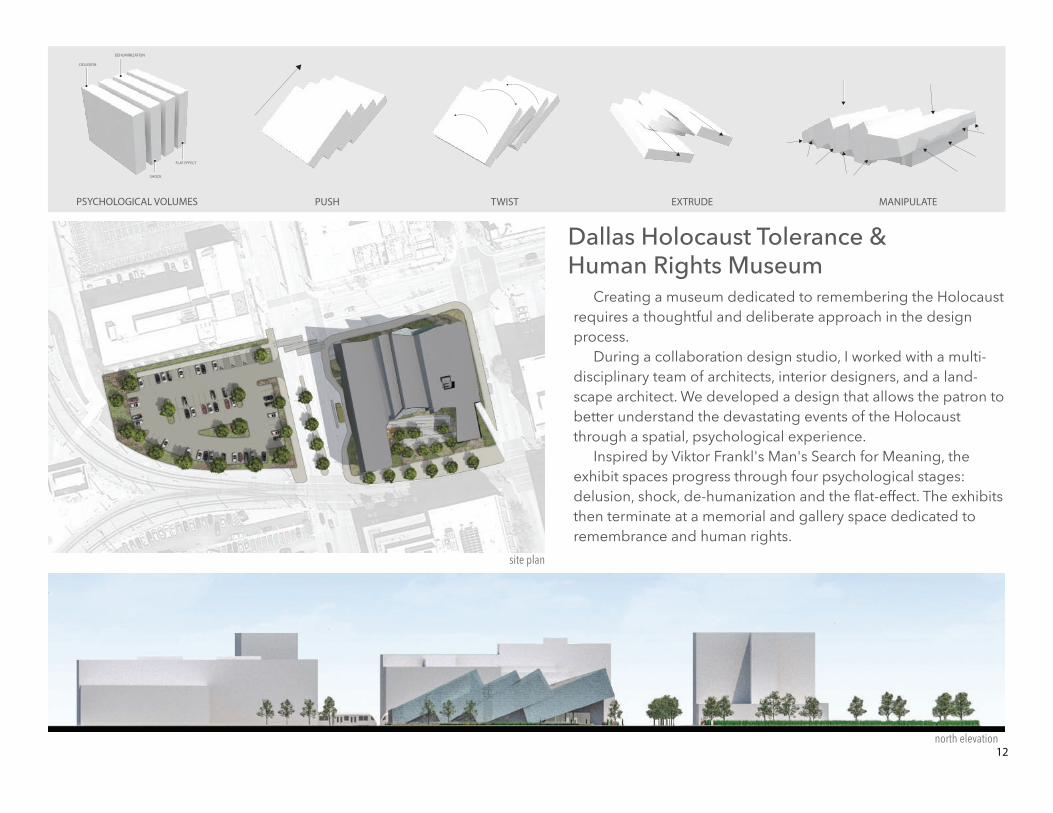
PSYCHOLOGICAL VOLUMES
DELUSION
DEHUMINIZATION
SHOCK
FLAT EFFECT
PUSH TWIST EXTRUDE MANIPULATE
site plan
12north elevation
Creating a museum dedicated to remembering the Holocaust requires a thoughtful and deliberate approach in the design process.
During a collaboration design studio, I worked with a multi-disciplinary team of architects, interior designers, and a land-scape architect. We developed a design that allows the patron to better understand the devastating events of the Holocaust through a spatial, psychological experience.
Inspired by Viktor Frankl's Man's Search for Meaning, the exhibit spaces progress through four psychological stages: delusion, shock, de-humanization and the flat-effect. The exhibits then terminate at a memorial and gallery space dedicated to remembrance and human rights.
Dallas Holocaust Tolerance & Human Rights Museum
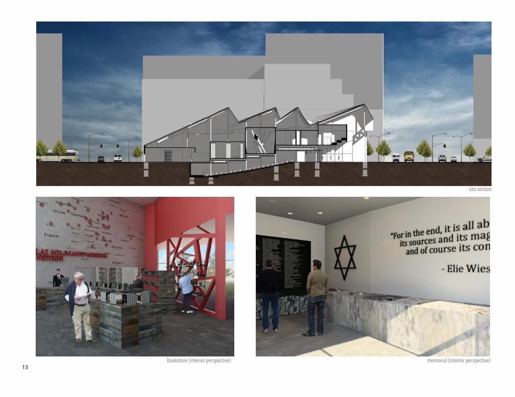
memorial (interior perspective)
site section
bookstore (interior perspective)13
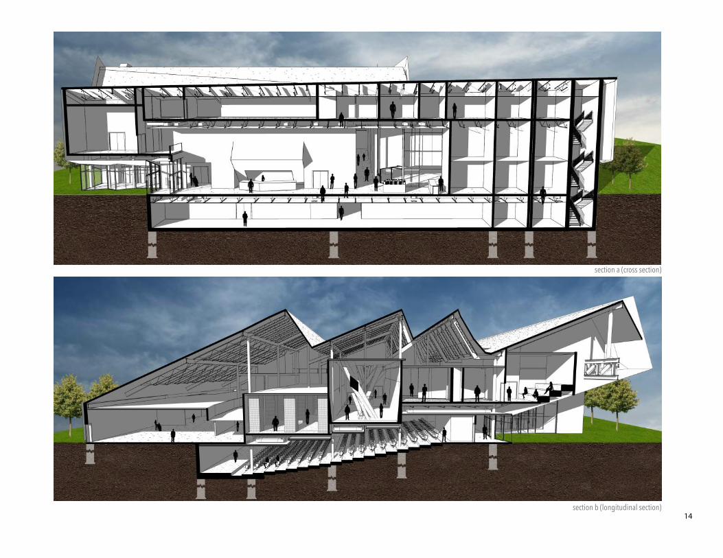
section b (longitudinal section)
section a (cross section)
14
UP
UP
UP
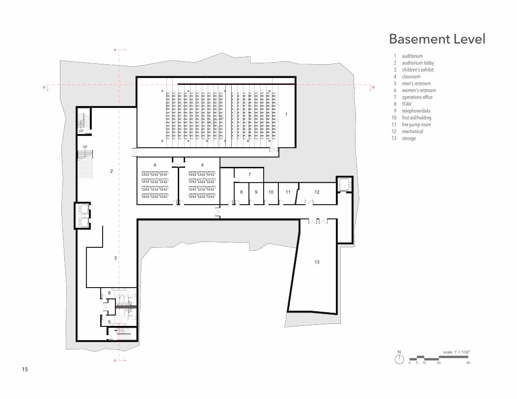
Basement Level
scale: 1’ = 1/32”N
0 5 10 20 40
442
3
7
1
8 9 10 11 12
13
6
5
123456789
10111213
auditoriumauditorium lobbychildren’s exhibitclassroommen’s restroomwomen’s restroomoperations officeIT/AVtelephone/datafirst aid/holdingfire pump roommechanicalstorage
BB
A
A
15
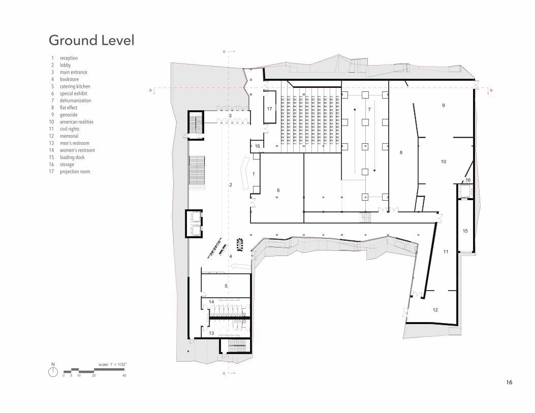
Ground Level
2
4
1
6
8
79
10
12
11
15
16
16
173
5
13
14
123456789
1011121314151617
receptionlobbymain entrancebookstorecatering kitchenspecial exhibitdehumanizationflat effectgenocideamerican realitiescivil rightsmemorialmen’s restroomwomen’s restroomloading dockstorageprojection room
scale: 1’ = 1/32”N
0 5 10 20 40
BB
A
A
16

DN
DN DN
DN
DN
DN
1
2
3
4
open to below
Orientation Level1234
orientation lobbyorientation roomdelusion exhibitshock exhibit
scale: 1’ = 1/32”N
0 5 10 20 40
BB
A
A
17
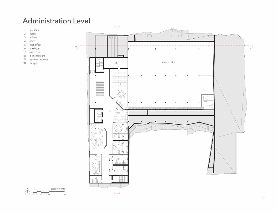
Administration Level
1
6
open to below
4
4
9
87
10
5
2
123456789
10
receptionlibraryarchivesofficeopen officesbreakroomconferencemen’s restroomwomen’s restroomstorage 3
scale: 1’ = 1/32”N
0 5 10 20 40
BB
A
A
18
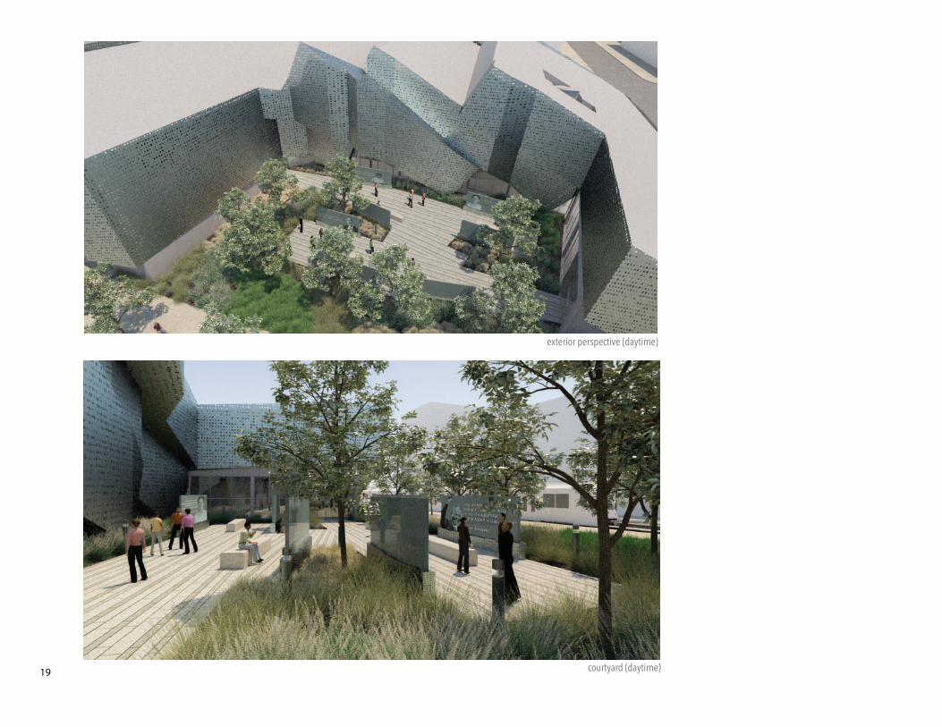
19
exterior perspective (daytime)
courtyard (daytime)
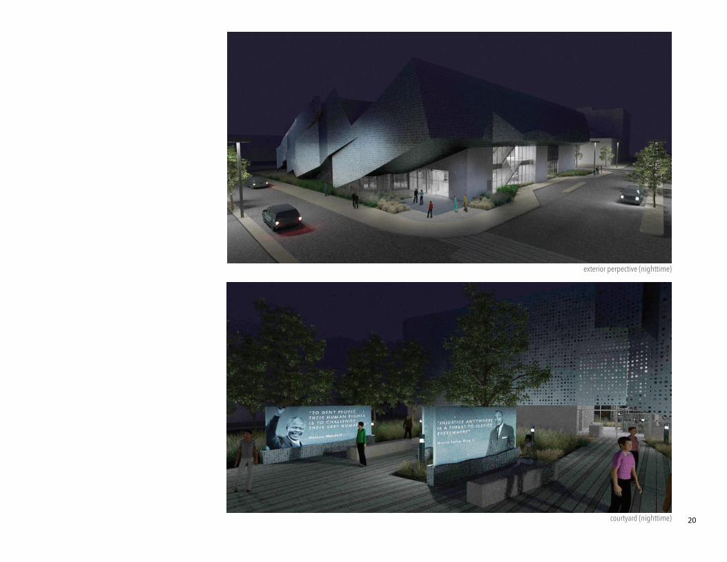
courtyard (nighttime) 20
exterior perpective (nighttime)
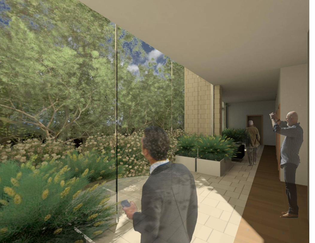
exterior perspective [ west ]
UP
1234567
89
1011
12131415
1617181920
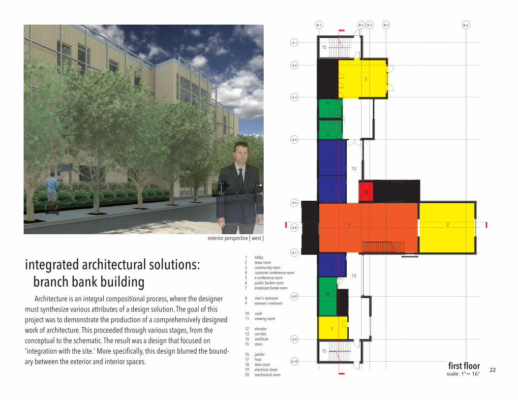
lobbytexas roomcommunity roomcustomer conference roome-conference roompublic banker roomemployee break room
men's restroomwomen's restroom
vaultviewing room
elevatorcorridorvestibulestairs
janitorhvacdata roomelectrical closetmechanical room
5
8
9
16
203
18
1917
6
4
1011
11
7
1 214
14
13
13
15
15
12
B.5B.4B.3B.2B.1
A.1
A.2
A.3
A.4
A.5
A.6
A.7
A.8
A.9
A.10
integrated architectural solutions: branch bank building
Architecture is an integral compositional process, where the designer must synthesize various attributes of a design solution. The goal of this project was to demonstrate the production of a comprehensively designed work of architecture. This proceeded through various stages, from the conceptual to the schematic. The result was a design that focused on 'integration with the site.' More specifically, this design blurred the bound-ary between the exterior and interior spaces. first floor
exterior perspective [ west ]
scale: 1”= 16”22
1
4
5
9
1210
11
8
13
7
6
1
7
8
1
1
2
1
1
1
DN
1
4
5
9
1210
11
8
133
7
6
1
7
8
1
1
2
1
1
1
top of roof
top of roof
open to below open to below
123
45
678
910111213
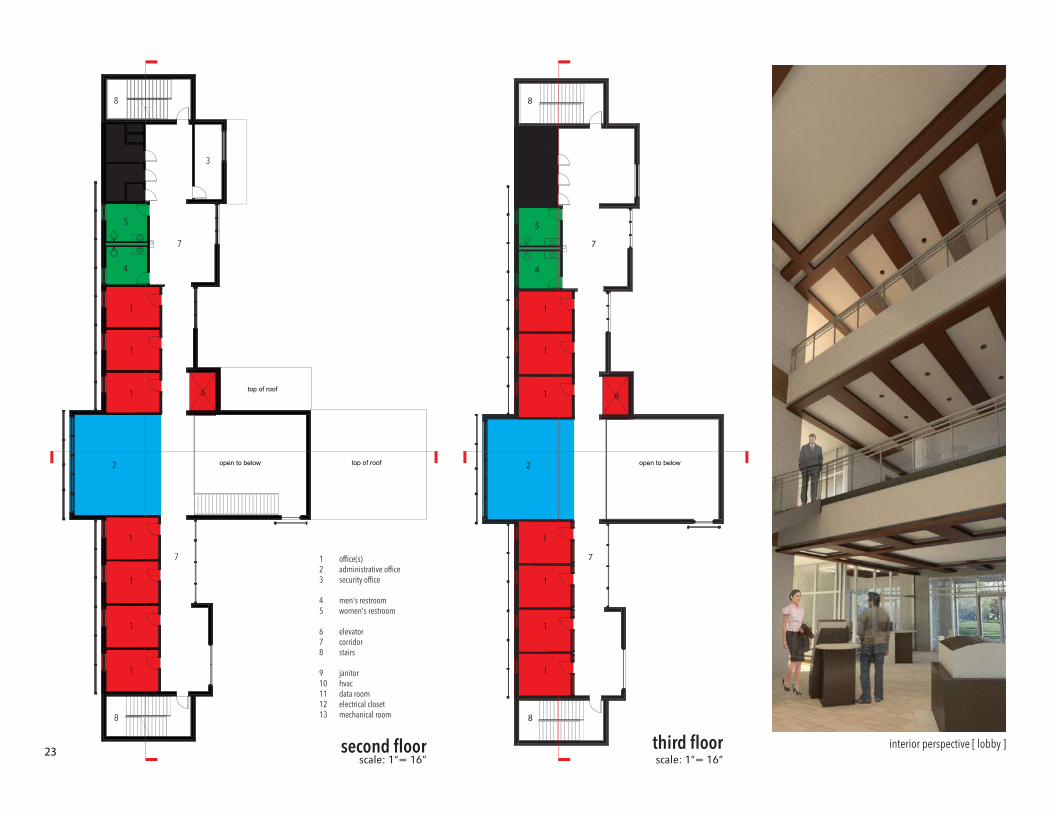
office(s)administrative officesecurity office
men's restroomwomen's restroom
elevatorcorridorstairs
janitorhvacdata roomelectrical closetmechanical room
second floor third floor interior perspective [ lobby ]scale: 1”= 16” scale: 1”= 16”
23
-0' - 6"
Top of Curve0' - 0"
Level 1- F.F.1' - 0"
Level 2- F.F.14' - 6 1/2"
Level 3- F.F.28' - 0 1/2"
T.O.R41' - 9"
Street Level
A.1 A.2 A.3 A.4 A.5 A.6 A.7 A.10A.9A.8
o�ce o�ce o�ce o�ceo�ceo�ceo�ce
administrative o�ce
e-conference room private bankerroom
cust. conferenceroom
employee roomcommunity room
stairs
men'sbath.
women'sbath.
administrative o�ce
o�ce o�ce o�ceo�ceo�ceo�ce
stairs
lobby
men'sbath.
women'sbath.
men'sbath.
women'sbath.
viewingroom
viewingroom
-0' - 6"
Top of Curve0' - 0"
Level 1- F.F.1' - 0"
Level 2- F.F.14' - 6 1/2"
Level 3- F.F.28' - 0 1/2"
T.O.R41' - 9"
Street Level
B.1B.2B.5 B.4 B.3
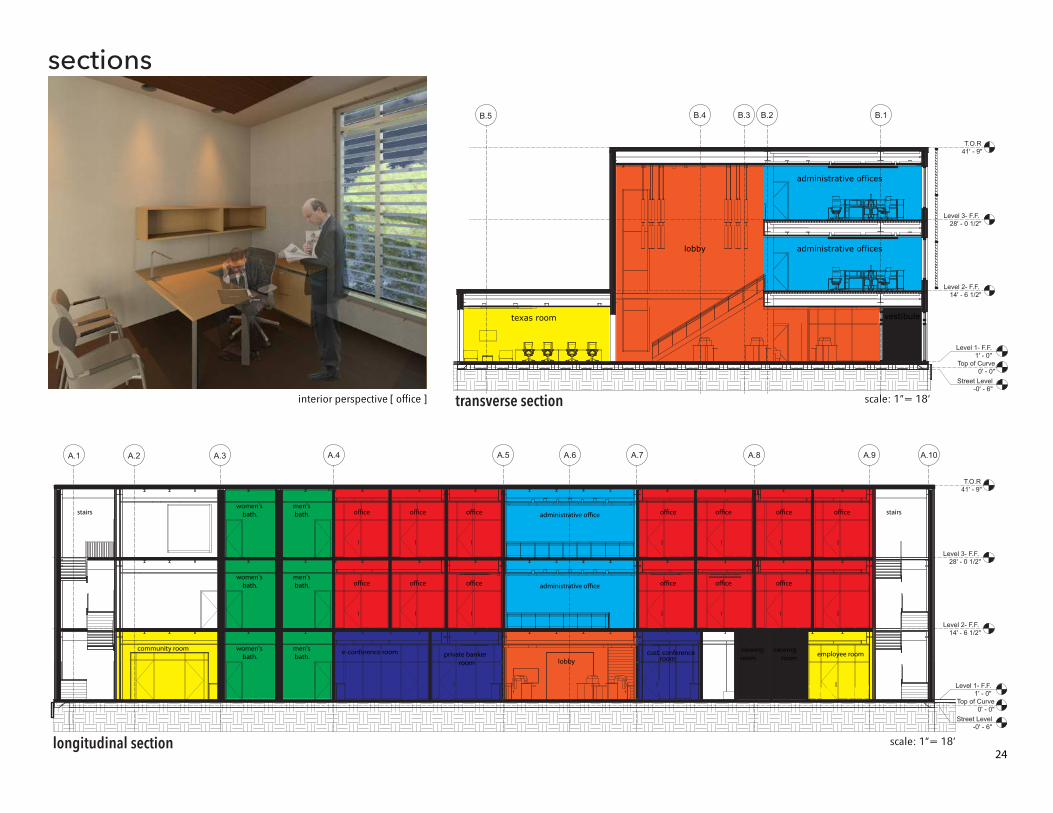
lobby administrative offices
administrative offices
texas room vestibule
sections
transverse section
longitudinal section scale: 1”= 18’
scale: 1”= 18’interior perspective [ office ]
24
Stre
et L
evel
-0' -
6"
Top
of C
urve
0' -
0"
Leve
l 1- F
.F.
1' -
0"
Leve
l 3- F
.F.
28' -
0 1
/2"
T.O
.R41
' - 9
"
Stre
et L
evel
-0' -
6"
Top
of C
urve
0' -
0"
Leve
l 1- F
.F.
1' -
0"
Leve
l 2- F
.F.
14' -
6 1
/2"
Leve
l 3- F
.F.
28' -
0 1
/2"
T.O
.R41
' - 9
"
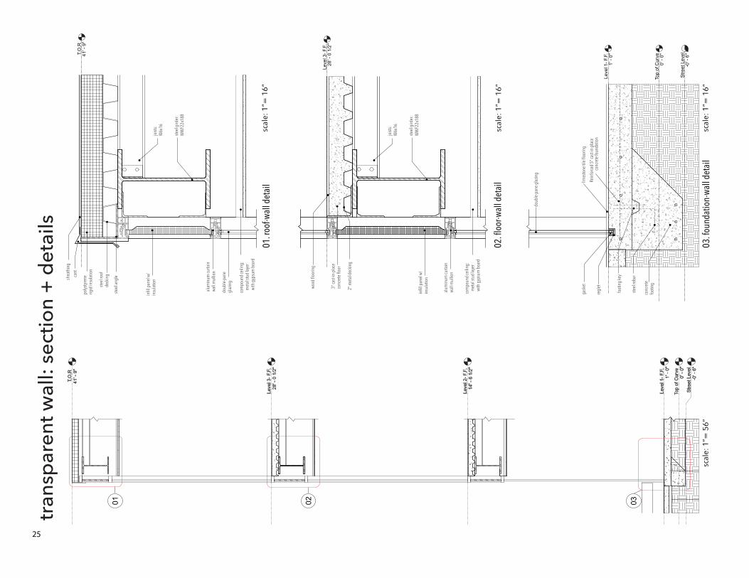
030201
tran
spar
ent w
all:
sect
ion
+ d
etai
ls
01. r
oof-w
all d
etai
l
02. f
loor
-wal
l det
ail
03. f
ound
atio
n-wa
ll de
tail
scal
e: 1
”= 5
6”sc
ale:
1”=
16”
scal
e: 1
”= 1
6”
scal
e: 1
”= 1
6”
25
Rein
forc
ed 5
" cas
t-in-
plac
eco
ncre
te fo
unda
tion
limes
tone
tile
floo
ring
foot
ing
key
doub
le-p
ane
glaz
ing
regl
et
gask
et
polys
tyre
ne
rigid
insu
latio
n
cant
shea
thin
g
steel
roof
de
ckin
g
steel
angl
e
doub
le-p
ane
glaz
ing
infil
l pan
el w
/in
sula
tion
alum
inum
curta
in
wall
mul
lion
2" m
etal
dec
king
3" ca
st-in
-pla
ce
conc
rete
floo
r
wood
floo
ring
steel
gird
er:
WW
F22x
188
infil
l pan
el w
/in
sula
tion
alum
inum
curta
in
wall
mul
lion
com
poun
d ce
iling
: m
etal
stud
laye
r w
ith g
ypsu
m b
oard
com
poun
d ce
iling
: m
etal
stud
laye
r w
ith g
ypsu
m b
oard
joist
s:W
6x16
steel
reba
r
conc
rete
fo
otin
g
steel
gird
er:
WW
F22x
188
joist
s:W
6x16
Stre
et L
evel
-0' -
6"
Top
of C
urve
0' -
0"
Leve
l 1- F
.F.
1' -
0"
Leve
l 3- F
.F.
28' -
0 1
/2"
T.O
.R41
' - 9
"
Stre
et L
evel
-0' -
6"
Top
of C
urve
0' -
0"
Leve
l 1- F
.F.
1' -
0"
Leve
l 2- F
.F.
14' -
6 1
/2"
Leve
l 3- F
.F.
28' -
0 1
/2"
T.O
.R41
' - 9
"
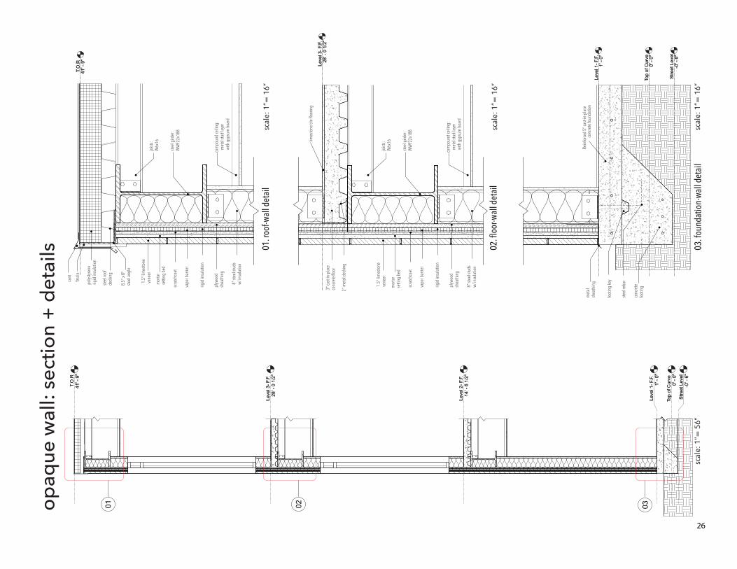
030201op
aque
wal
l: se
ctio
n +
det
ails 01
. roo
f-wal
l det
ail
02. f
loor
-wal
l det
ail
03. f
ound
atio
n-wa
ll de
tail
scal
e: 1
”= 5
6”sc
ale:
1”=
16”
scal
e: 1
”= 1
6”
scal
e: 1
”= 1
6”
26
cant
8" st
eel s
tuds
w/
insu
latio
n
8.5"
x 8"
ste
el an
gle
1.5"
lim
esto
ne
vene
er
mor
tar
setti
ng b
ed
scra
tchco
at
rigid
insu
latio
n
plyw
ood
shea
thin
g
3" ca
st-in
-pla
ce
conc
rete
floo
r
com
poun
d ce
iling
: m
etal
stud
laye
r w
ith g
ypsu
m b
oard
fasc
ia
vapo
r bar
rier
8" st
eel s
tuds
w/
insu
latio
n
1.5"
lim
esto
ne
vene
er
mor
tar
setti
ng b
ed
scra
tchco
at
rigid
insu
latio
n
plyw
ood
shea
thin
g
vapo
r bar
rier
met
al
shea
thin
gpolys
tyre
ne
rigid
insu
latio
n
steel
roof
de
ckin
g
steel
gird
er:
WW
F22x
188
joist
s:W
6x16
steel
gird
er:
WW
F22x
188
joist
s:W
6x16
Rein
forc
ed 5
" cas
t-in-
plac
eco
ncre
te fo
unda
tion
limes
tone
tile
floo
ring
foot
ing
key
steel
reba
r
conc
rete
fo
otin
g
2" m
etal
dec
king
com
poun
d ce
iling
: m
etal
stud
laye
r w
ith g
ypsu
m b
oard
-2'
-1'
0'
1'
2'
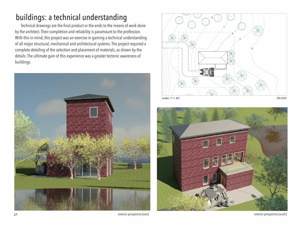
N
site planscale: 1”= 42’
exterior perspective [south]exterior perspective [east]
buildings: a technical understandingTechnical drawings are the final product or the ends to the means of work done
by the architect. Their completion and reliability is paramount to the profession. With this in mind, this project was an exercise in gaining a technical understanding of all major structural, mechanical and architectural systems. The project required a complete detailing of the selection and placement of materials, as shown by the details. The ultimate gain of this experience was a greater tectonic awareness of buildings.
27
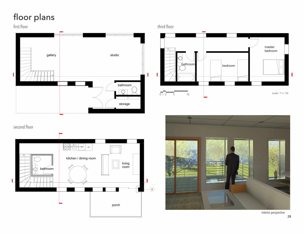
DN
bedroom
masterbedroom
bathroom
DN
UP
REF.DW
livingroom
kitchen / dining room
bathroom
porch
4
UP
bathroom
storage
studiogallery
0 521 10 scale: 1”= 10’
interior perspective
first floor
second floor
third floor
floor plans
28
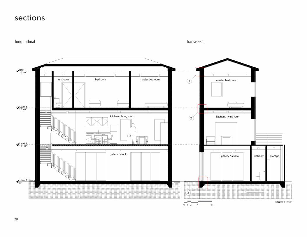
kitchen / living room
master bedroom
gallery / studio restroom storage
Level 10"
Level 210' - 0"
Level 320' - 0"
Roof30' - 0"
3
1
2
bedroom master bedroomrestroom
gallery / studio
kitchen / living room
0 421 8scale: 1”= 8’
longitudinal transverse
sections
29
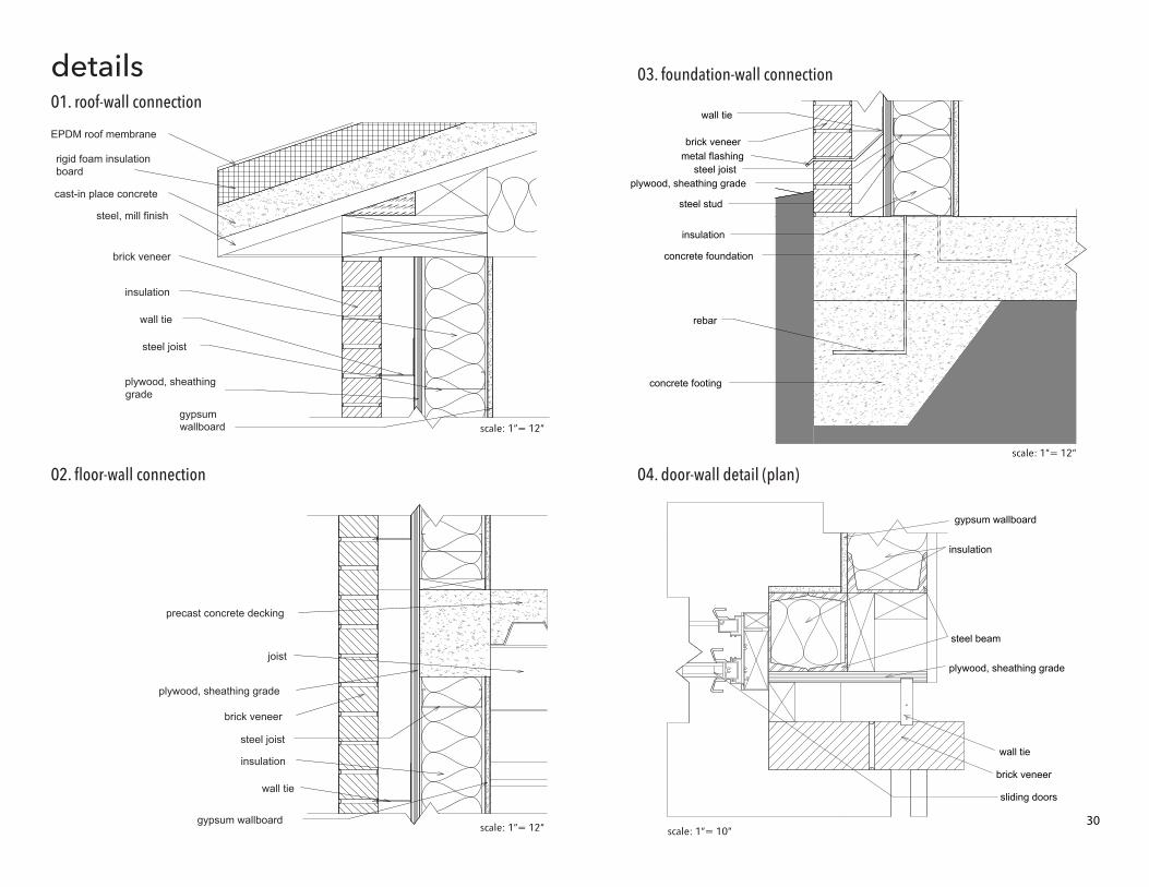
EPDM roof membrane
rigid foam insulationboard
cast-in place concrete
steel, mill finish
brick veneer
wall tie
steel joist
insulation
plywood, sheathinggrade
gypsumwallboard
brick veneer
plywood, sheathing grade
wall tie
insulation
precast concrete decking
gypsum wallboard
joist
steel joist
brick veneermetal flashing
wall tie
plywood, sheathing grade
steel stud
steel joist
insulation
concrete foundation
concrete footing
rebar
brick veneer
wall tie
plywood, sheathing grade
sliding doors
insulation
gypsum wallboard
steel beam
scale: 1”= 12”
scale: 1”= 12”
scale: 1”= 12”
scale: 1”= 10”
02. floor-wall connection 04. door-wall detail (plan)
03. foundation-wall connection
01. roof-wall connection
details
30
0
N
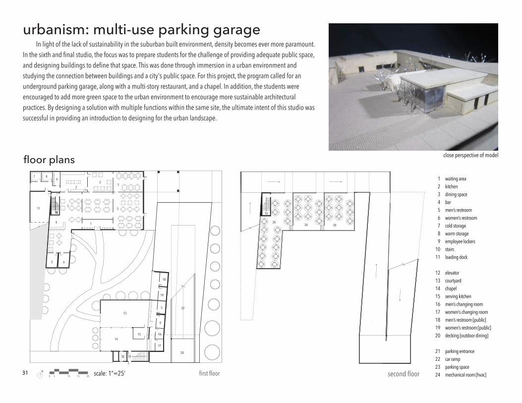
5 10 15 20 first floorscale: 1”=25’ second floor
close perspective of modelfloor plans
urbanism: multi-use parking garageIn light of the lack of sustainability in the suburban built environment, density becomes ever more paramount.
In the sixth and final studio, the focus was to prepare students for the challenge of providing adequate public space, and designing buildings to define that space. This was done through immersion in a urban environment and studying the connection between buildings and a city's public space. For this project, the program called for an underground parking garage, along with a multi-story restaurant, and a chapel. In addition, the students were encouraged to add more green space to the urban environment to encourage more sustainable architectural practices. By designing a solution with multiple functions within the same site, the ultimate intent of this studio was successful in providing an introduction to designing for the urban landscape.
31
123456789
1011
121314151617181920
21222324
waiting areakitchendining spacebarmen’s restroomwomen’s restroomcold storagewarm storageemployee lockersstairsloading dock
elevatorcourtyardchapelserving kitchenmen’s changing roomwomen’s changing roommen’s restroom [public]women’s restroom [public]decking [outdoor dining]
parking entrancecar rampparking spacemechanical room [hvac]
1
10
4
3
33
2
5
5 6
6
16
19
17
20
22
18
987
3
12
1415
13
1011
10
202020
10
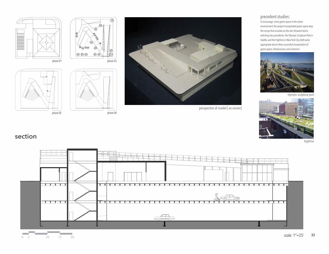
phase 03phase 01
phase 02 phase 04
highline
olympic sculpture park
0 5 10 15 20 scale: 1”=25’
perspective of model [ se corner]
precedent studies:
section
To encourage more green space in the urban
environment, the project incorporated green space atop
the ramps that circulate on the site. Research led to
selecting two precedents: the Olympic Sculpture Park in
Seattle, and the Highline in New York City. Both were
appropriate due to their successful incorporation of
green space, infrastructure, and urbanism.
32
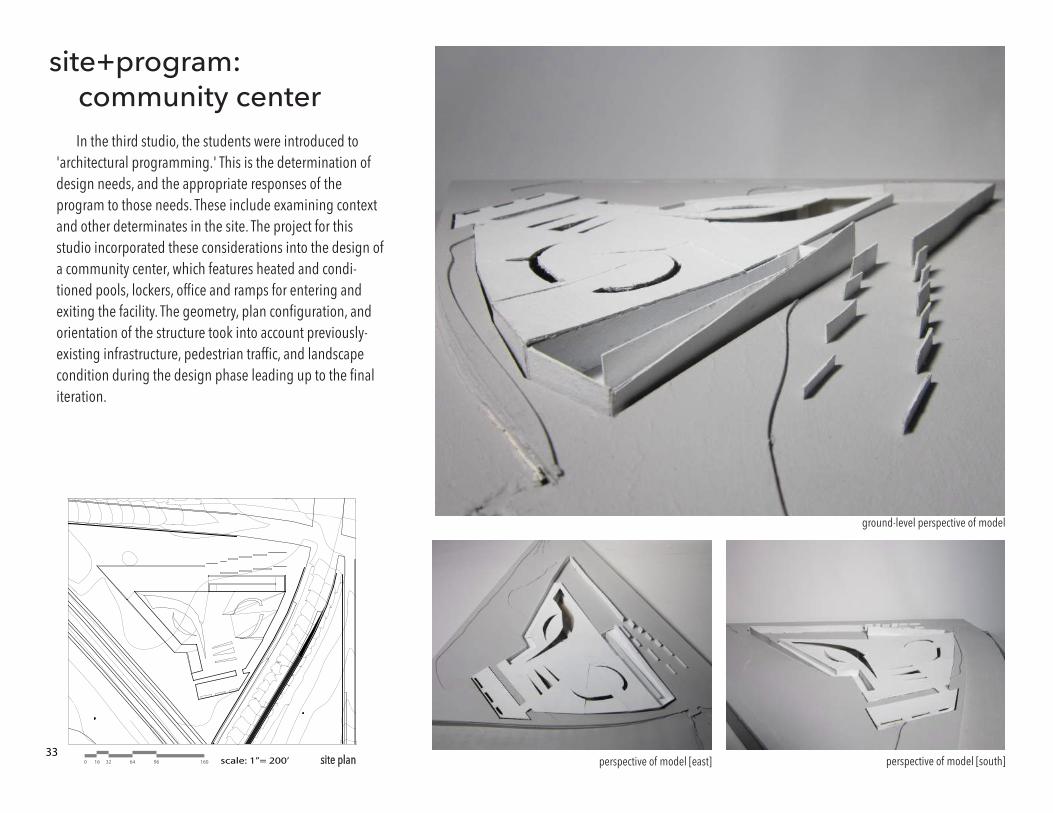
perspective of model [south]site plan
ground-level perspective of model
perspective of model [east]0 643216 96 160 scale: 1”= 200’
site+program: community center
In the third studio, the students were introduced to 'architectural programming.' This is the determination of design needs, and the appropriate responses of the program to those needs. These include examining context and other determinates in the site. The project for this studio incorporated these considerations into the design of a community center, which features heated and condi-tioned pools, lockers, office and ramps for entering and exiting the facility. The geometry, plan configuration, and orientation of the structure took into account previously-existing infrastructure, pedestrian traffic, and landscape condition during the design phase leading up to the final iteration.
33
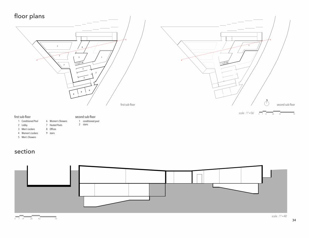
first sub-floor second sub-floor
scale : 1”=56’
scale : 1”=48’
0 28147 42 70
1
2
12345
Conditioned PoolLobbyMen’s LockersWomen’s LockersMen’s Showers
6789
Women’s ShowersHeated PoolsOfficesstairs
12
conditioned poolstairs
second sub-floor
1
2
3
9
4
5
6
88
8
7
7
7
first sub-floor
N
0 28147 42 70
section
floor plans
34
Scale: 1/4” = 1’-0”
01. sectionScale: 1/4” = 1’-0”
02. elevation
D.05
3.0D.0B.0
D.04
D.03
T.O. Roof
B.O. Roof
T.O. Plate @ Catwalk19’-0 3/8”
1’-10”
22’-6 3/8”
B.O. Screen Wall
Slab @ Sidewalk
04
01
Footing with keyed Joint
0’-0”T.O. Slab @ GroundFloor
05
06
03
02
01
02
03
04
05
06
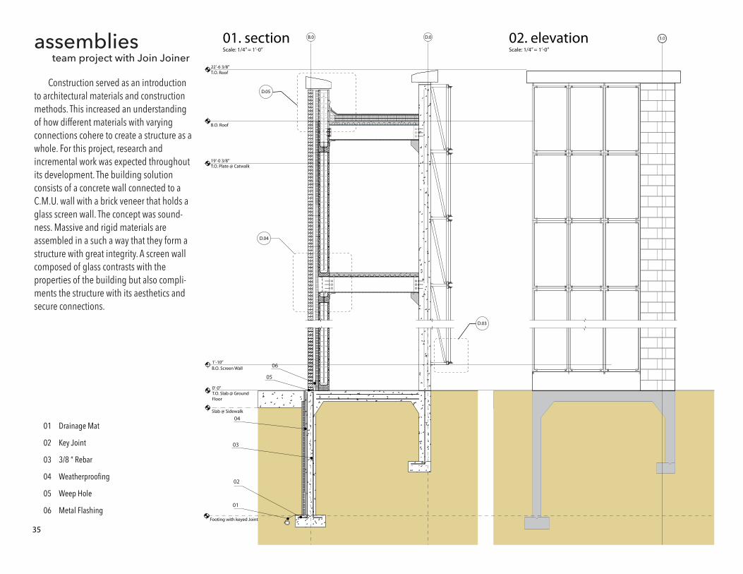
Drainage Mat
Key Joint
3/8 “ Rebar
Weatherproofing
Weep Hole
Metal Flashing
assemblies team project with Join Joiner
Construction served as an introduction to architectural materials and construction methods. This increased an understanding of how different materials with varying connections cohere to create a structure as a whole. For this project, research and incremental work was expected throughout its development. The building solution consists of a concrete wall connected to a C.M.U. wall with a brick veneer that holds a glass screen wall. The concept was sound-ness. Massive and rigid materials are assembled in a such a way that they form a structure with great integrity. A screen wall composed of glass contrasts with the properties of the building but also compli-ments the structure with its aesthetics and secure connections.
35
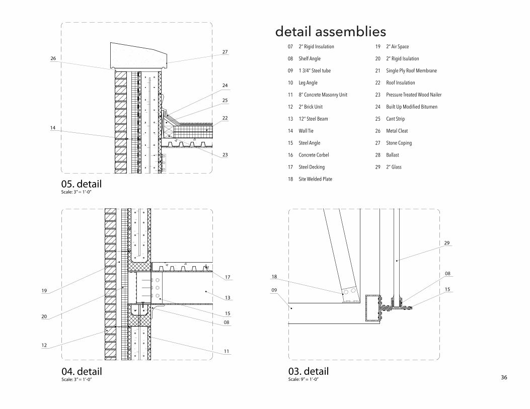
Scale: 9” = 1’-0”03. detail
Scale: 3” = 1’-0”05. detail
Scale: 3” = 1’-0”04. detail
07
08
09
10
11
12
13
14
15
16
17
18
2” Rigid Insulation Shelf Angle
1 3/4” Steel tube
Leg Angle
8” Concrete Masonry Unit
2“ Brick Unit
12” Steel Beam
Wall Tie
Steel Angle
Concrete Corbel
Steel Decking
Site Welded Plate
19
20
21
22
23
24
25
26
27
28
29
2” Air Space
2” Rigid Isulation
Single Ply Roof Membrane
Roof Insulation
Pressure Treated Wood Nailer
Built Up Modified Bitumen
Cant Strip
Metal Cleat
Stone Coping
Ballast
2” Glass
27
24
25
23
14
22
26
18
29
1509
08
08
1112
15
17
13
20
19
detail assemblies
36