Embed Size (px)
Citation preview
ES
DE
FR
EN
IT
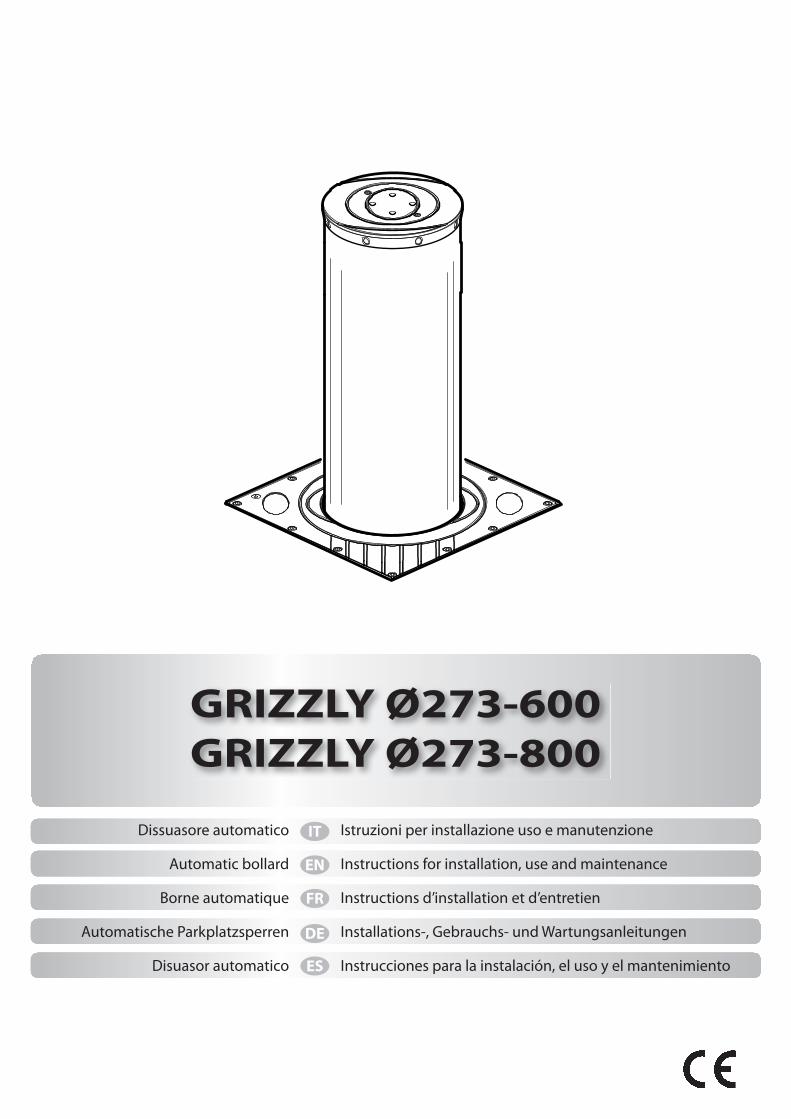
GRIZZLY Ø273-600
GRIZZLY Ø273-800
Dissuasore automatico
Automatic bollard
Borne automatique
Automatische Parkplatzsperren
Disuasor automatico
Istruzioni per installazione uso e manutenzione
Instructions for installation, use and maintenance
Instructions d’installation et d’entretien
Installations-, Gebrauchs- und Wartungsanleitungen
Instrucciones para la instalación, el uso y el mantenimiento
- 2 -
Il libretto di INSTALLAZIONE USO E MANUTENZIONE è destinato agli installatori, agli utilizzatori ed agli operatori della manutenzione.
Leggere attentamente il libretto prima di installare il prodotto, utilizzarlo e prima di eseguire manutenzione ordinaria o straordinaria.
Le operazioni che, se non eff ettuate correttamente, possono presentare rischi, sono indicate con i simboli: Il costruttore non è responsabile per danni arrecati a persone, animali o cose dovuti ad applicazioni che superano i limiti indicati nella scheda tecnica allegata o dall’uso diverso da quello per cui il prodotto è stato progettato.
Le indicazioni precedute da questo simbolo contengono informazioni di particolare importanza, il loro mancato rispetto può
comportare la perdita della garanzia contrattuale.
GENERALITÀ
Il dissuasore è la soluzione ideale per la gestione del traffi co veicolare nel rispetto dei moderni canoni di arredo urbano. Può essere utilizzato per applicazioni di controlli accessi o per tutelare aree private con la massima sicurezza.
DATI TECNICI
The INSTALLATION, USE AND MAINTENANCE handbook is for installers, users and maintenance engineers.
Please read it carefully before installing the appliance, before using it and before routine or extraordinary maintenance work.
Operations that, if not carried out correctly, can be risky, are indicated with the following symbols: The manufacturer is not liable for injury to people or animals or damage to things in the case of applications that exceed the limits specifi ed on the enclosed technical data sheet or by a use diff erent from what the appliance has been designed.
The notices preceded by this symbol provide important information, the non-compliance with such instructions voids the
manufacturer’s guarantee.
GENERAL
The deterrent bollard is the ideal solution for managing vehicle traffi c in compliance with modern urban furnishing requirements. It can be used to contol entrances or to safeguard private areas in total safety.
TECHNICAL SPECIFICATIONS
Cette notice est destinée aux installateurs, aux utilisateurs et aux techniciens chargés de l’entretien.
Lisez attentivement cette notice, avant d’installer l’automatisme, de l’utiliser et avant de procéder à son entretien ordinaire ou extraordinaire.
Les opérations présentant des risques si elles ne sont pas eff ectuées correctement sont signalées avec les symboles: Le fabribant décline toute responsabilité en cas de dégâts à des personnes, animaux ou biens provoqués par des applications dépassant les limites prévues dans la fi che technique jointe ou par un usage diff érent de celui pour lequel l’automatisme a été conçu.
Les indications précédées de ce symbole contiennent des informations importantes, le non-respect de ces indications peut invalider la garantie du
constructeur.
GENERALITES
La borne escamotable est la solution idéale pour contrôler le trafi c routier selon les concepts modernes de mobilier urbain. Elle contrôle l’accès ou protège les espaces privés en toute sécurité.
DONNÉES TECHNIQUES
Alimentazione....................................................230 Vac ± 10% ; 50÷60 Hz; 500 W
Frequenza di lavoro.........................................................................................3000 / 24hGrado di protezione.....................................................................................................IP67
Centralina........................................................................................................CDS / CDS-K
Tempo di lavoro...................................................................5 s. (GRZ/6); 6,5 s. (GRZ/8)
Temp. di esercizio..........................................................................-40 *** +60 °CPeso netto.........................................................136 kg (GRZ/6); 149 kg (GRZ/8)Peso lordo.........................................................142 kg (GRZ/6); 157 kg (GRZ/8)*** Con riscaldatore integrato attivo (CDS-K)
Power.....................................................................230 Vac ± 10% ; 50÷60 Hz; 500 W
Working frequency..........................................................................................3000 / 24hProtection level..............................................................................................................IP67
Control unit.....................................................................................................CDS / CDS-K
Working time........................................................................5 s. (GRZ/6); 6,5 s. (GRZ/8)
Working temp...................................................................................-40 *** +60 °CNet weight...........................................................136 kg (GRZ/6); 149 kg (GRZ/8)Gross weight.......................................................142 kg (GRZ/6); 157 kg (GRZ/8)*** With integrated heater active (CDS-K)
Alimentation......................................................230 Vac ± 10% ; 50÷60 Hz; 500 W
Duree de l’operation.......................................................................................3000 / 24hIndice de protection....................................................................................................IP67
Centrale............................................................................................................CDS / CDS-K
Temps de travail............................................................5 s. (GRZ/6); 6,5 s. (GRZ/8)
Température d’exercice.................................................................-40 *** +60 °CPoids net..............................................................136 kg (GRZ/6); 149 kg (GRZ/8)Poids brut............................................................142 kg (GRZ/6); 157 kg (GRZ/8)*** Avec chauff age intégré actif (CDS-K)
IT
EN
FR
- 3 -
Das INSTALLATIONS-, BETRIEBS- UND WARTUNGSHANDBUCH ist für die Installateure, Anwender und Wartungsfachmänner bestimmt.
Das Handbuch ist vor der Installation des Produkts sowie vor der ordentlichen und außerordentlichen Wartung sorgfältig zu lesen.
Wenn die durch folgende Symbole gekennzeichneten Eingriff e nicht korrekt durchgeführt werden, kann es zu Gefahrsituationen kommen: Die Firma Hersteller haftet nicht für Personen-, Tier- oder Sachschäden, die auf eine unsachgemäße Anwendung des Produkts sowie auf das Überschreiten der im technischen Blatt angegebenen Grenzwerte zurückzuführen sind.
Die Angaben, denen dieses Symbol vorangestellt ist, enthalten Informationen zu allen möglichen Themen von bes onderer
Bedeutung, ihre Nichtbeachtung kann zum Verlust der vertraglichen Garantie führen.
ALLGEMEINES
Der versenkbare Poller ist die ideale Lösung zum Verwalten des Straßenverkehrs unter Berücksichtigung der modernen Stadteinrichtung. Der Poller kann unter Gewährleistung der maximalen Sicherheit für die Zufahrtskontrolle oder zum Absperren von Privatbereichen verwendet werden.
TECHNISCHE DATEN
El folleto de INSTALACIÓN, USO Y MANTENIMIENTO se destina a instaladores, usuarios y operadores de mantenimiento.
Leer detenidamente el folleto antes de instalar el producto, utilizarlo y efectuar el mantenimiento ordinario o extraordinario.
Las operaciones que, si no son efectuadas correctamente, pueden conllevar riesgos, vienen indicadas con los símbolos: El fabricante no es responsable de daños causados a personas, animales o cosas, debidos a aplicaciones que superen los límites indicados en la fi cha técnica adjunta o debidos a utilización diferente de aquella apra la cual el producto fue proyectado.
Las indicaciones precedidas por este símbolo contienen informaciones sobre cualquier asunto de importancia particular, no respetarlas puede
comportar la perdida de la garantía contractual.
GENERALIDAD
El disuasor es la solución ideal para la gestión del tráfi co de vehículos respetando los modernos cánones del mobiliario urbano. Se puede utilizar para aplicaciones de control de accesos o para proteger áreas privadas con la máxima seguridad.
DATOS TÉCNICOS
Stromversorgung..........................................230 Vac ± 10% ; 50÷60 Hz; 500 W
Einsatzfrequenz............................................................................................3000 / 24hSchutzgrad..................................................................................................................IP67
Steuergerät.................................................................................................CDS / CDS-K
Arbeitszeit.........................................................................5 s. (GRZ/6); 6,5 s. (GRZ/8)
Betriebstemperatur............................................................................-40 *** +60 °CReingewicht..............................................................136 kg (GRZ/6); 149 kg (GRZ/8)Bruttogewicht..........................................................142 kg (GRZ/6); 157 kg (GRZ/8)*** Mit integrierter Heizung aktiv (CDS-K)
Alimentación..................................................230 Vac ± 10% ; 50÷60 Hz; 500 W
Frecuencia de trabajo.................................................................................3000 / 24hGrado de protección...............................................................................................IP67
Central..........................................................................................................CDS / CDS-K
Tiempo de trabajo..........................................................5 s. (GRZ/6); 6,5 s. (GRZ/8)
Temp. de operación................................................................................-40 *** +60 °CPeso neto...................................................................136 kg (GRZ/6); 149 kg (GRZ/8)Peso bruto..................................................................142 kg (GRZ/6); 157 kg (GRZ/8)*** Con calentador integrado activo (CDS-K)
DE
ES
- 4 -
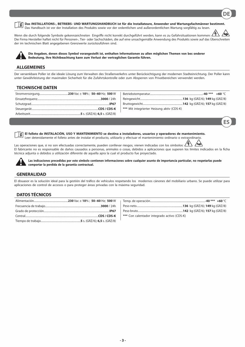
DISPOSIZIONE • LAYOUT • DISPOSITION • LAYOUT • DISPOSICIÓN
A Asfalto - Road surface - Asphalte - Asphalt - Asfalto
B Cemento - Cement - Ciment - Zement - Cemento
C Guaina Ø50 - Sheathing Ø50 - Gaine Ø50 - Anschluss Ø50 - Vaina Ø50
DSabbia compatta - Compact sand - Sable compact - VerdichtetetsandArena compacta
E Sabbia fi ne - Fine sand - Sable fi n - Feiner sand - Arena fi na
F Ghiaia - Pebble gravel - Gravier - Kies - Gravilla
GDrenaggio Ø125 - Drainage Ø125 - Drainage Ø125 - Drainage Ø125Drenaje Ø125
H
Allacciamento alla rete fognaria - Connection to the sewer networkRaccordement au tout-à-l’égout - Anschluss an das AbwassernetzConexión a la red de alcantarillado
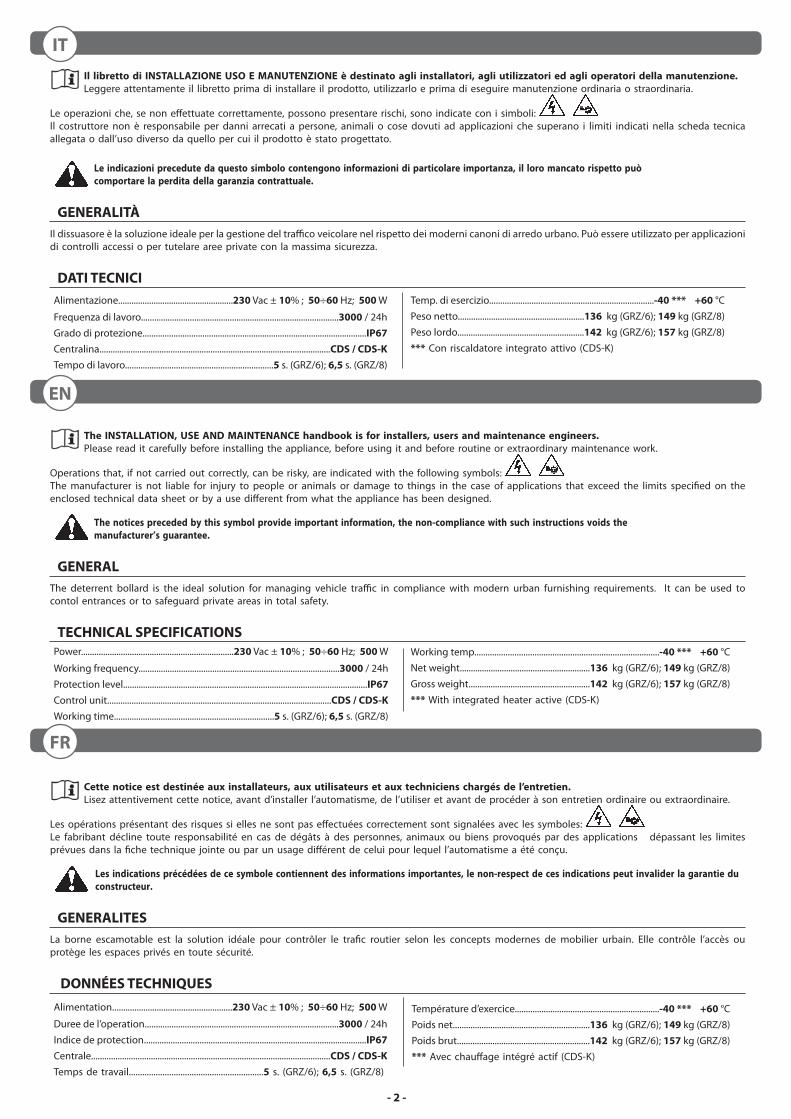
DIMENSIONI D’INGOMBRO • OVERALL SIZE DIMENSIONS • DIMENSIONS D’ENCOMBREMENTRAUMBEDARF - ABMESSUNGEN • DIMENSIONES MÁXIMAS
FILO TERRAGROUND SURFACE LEVELSOL FINIBODENNIVEAUNIVEL DEL PAVIMENTO
Ø280
270
Ø354
480
480
1
2
270
A B
C
D
E
F
G
H
Ø273
TUTTE LE DIMENSIONI IN mm • ALL DIMENSIONS IN mm • TOUTES LES DIMENSIONES EN MM ALLE ABMESSUNGEN IN mm • TODAS LAS DIMENSIONES EN mm
600
(GRI
ZZLY
600
)86
0 (G
RIZZ
LY 6
00)
800
(GRI
ZZLY
800
)10
60 (G
RIZZ
LY 8
00)
1100
(GRI
ZZLY
600
)
1300
(GRI
ZZLY
800
)
860
(GRI
ZZLY
600
)
1060
(GRI
ZZLY
800
)
IT EN FR DE ES
- 5 -
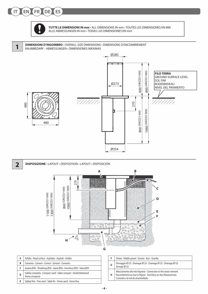
NOTA CAVI • WIRING NOTE • BRANCHEMENTS • BEMERKUNG ZU DEN KABEL ANSCHLÜSSEN • NOTA CABLES
1000 ÷ 1200 1000 ÷ 1200
FONDAZIONE • FOUNDATION • FONDATION • FUNDAMENT • FOSA
3
4
3
1 Linea Monofase - Single-phase line - Ligne monophasèe - Einphasenleitung - Linea monofàsica H05VV 2 x 1,5 + T
2 Ricevitore - Receiver - Rècepteur - Empfänger - Receptor 4 x 0,5
3 SOS 4 x 0,5
4 Lampeggiante - Flasher - Clignotant - Blinkleuchte - Indicador intermitente 2 x 0,5
5 Selettore a chiave - Key selector - Sèlecteur à clè - Schlüsselschalter - Selector de llave 2 x 0,5
6 GRIZZLY
Cavo in dotazione
Cable supplied by us
Cable fourni en dotation
Kabel beigestellt
Cable incluido
7 Rivelatore magnetico - Magnetic detector - Dètecteur magnètique - Magnetdetektor - Detector magnético
Cavo intrecciato
Twisted cable
Torsade de conducteurs
Verdrilltes Kabel
Cable trenzado
8 Fotocellula trasmettitore - Trasmitter photocell - Photocellule èmettrice - Senderfotozelle - Fotocèlula transmisor 2 x 0,5
9 Fotocellula ricevitore - Receiver photocell - Photocellule rèceptrice - Empfängerfotozelle - Fotocèlula receptor 4 x 0,5
10 Semaforo - Traffi c light - Feu tricolore - Ampel - Semáforo 3 x 0,5 + T
1200
(GRI
ZZLY
600
)
1400
(GRI
ZZLY
800
)
ESDEFRENIT
- 6 -
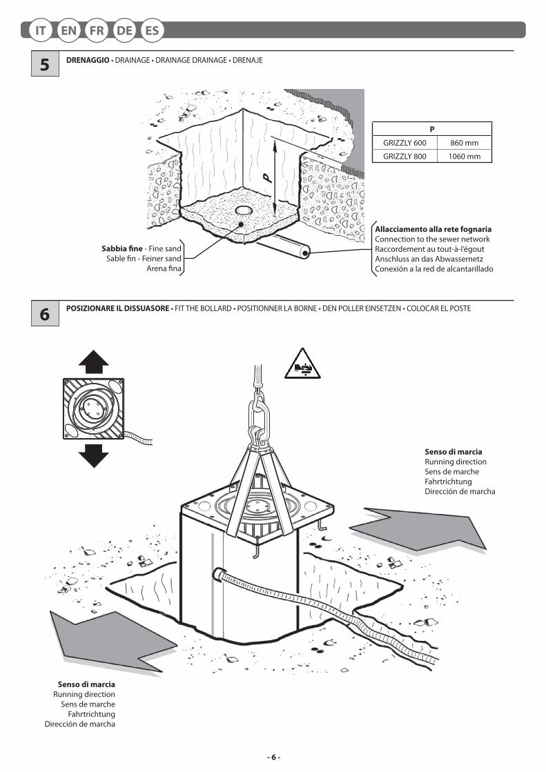
P
Sabbia fi ne - Fine sandSable fi n - Feiner sand
Arena fi na
DRENAGGIO • DRAINAGE • DRAINAGE DRAINAGE • DRENAJE
POSIZIONARE IL DISSUASORE • FIT THE BOLLARD • POSITIONNER LA BORNE • DEN POLLER EINSETZEN • COLOCAR EL POSTE
Senso di marcia
Running directionSens de marche
FahrtrichtungDirección de marcha
Allacciamento alla rete fognaria
Connection to the sewer networkRaccordement au tout-à-l’égoutAnschluss an das AbwassernetzConexión a la red de alcantarillado
5
6
Senso di marcia
Running directionSens de marcheFahrtrichtungDirección de marcha
P
GRIZZLY 600 860 mm
GRIZZLY 800 1060 mm
IT EN FR DE ES
- 7 -
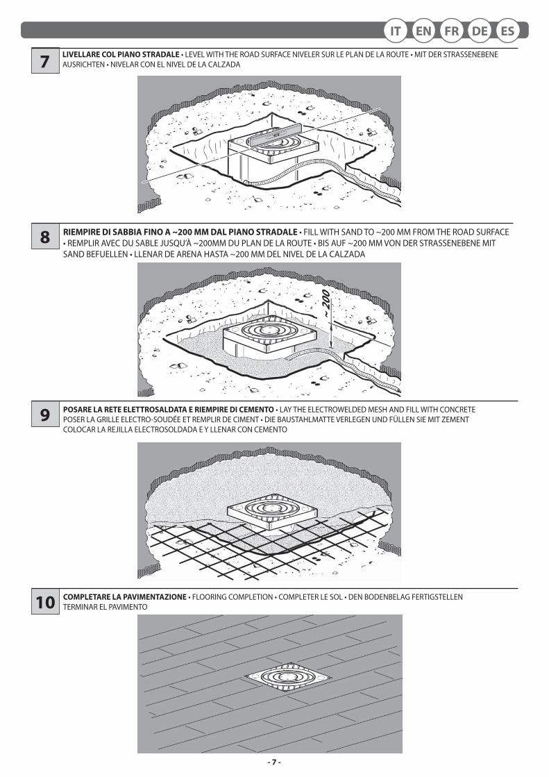
COMPLETARE LA PAVIMENTAZIONE • FLOORING COMPLETION • COMPLETER LE SOL • DEN BODENBELAG FERTIGSTELLENTERMINAR EL PAVIMENTO
POSARE LA RETE ELETTROSALDATA E RIEMPIRE DI CEMENTO • LAY THE ELECTROWELDED MESH AND FILL WITH CONCRETEPOSER LA GRILLE ELECTRO-SOUDÉE ET REMPLIR DE CIMENT • DIE BAUSTAHLMATTE VERLEGEN UND FÜLLEN SIE MIT ZEMENTCOLOCAR LA REJILLA ELECTROSOLDADA E Y LLENAR CON CEMENTO
10
9
LIVELLARE COL PIANO STRADALE • LEVEL WITH THE ROAD SURFACE NIVELER SUR LE PLAN DE LA ROUTE • MIT DER STRASSENEBENE AUSRICHTEN • NIVELAR CON EL NIVEL DE LA CALZADA7
~ 2
00
RIEMPIRE DI SABBIA FINO A ~200 MM DAL PIANO STRADALE • FILL WITH SAND TO ~200 MM FROM THE ROAD SURFACE • REMPLIR AVEC DU SABLE JUSQU’À ~200MM DU PLAN DE LA ROUTE • BIS AUF ~200 MM VON DER STRASSENEBENE MIT SAND BEFUELLEN • LLENAR DE ARENA HASTA ~200 MM DEL NIVEL DE LA CALZADA
8
ESDEFRENIT
- 8 -
blac
k
yello
w/g
reen
bro
wn
gre
y (*
)
blue
red
and
red/
whi
te
yel
low
and
yel
low
/whi
te
orange and orange/white
whi
te a
nd w
hite
/bla
ck
gree
n an
d gr
een/
whi
te
pin
k an
d pi
nk/w
hite
MO
TAGND C
OM
MO
TB EV EV
M
24 V
ac
LED BZ BZ
FCA
CO
M
FCC
CO
M
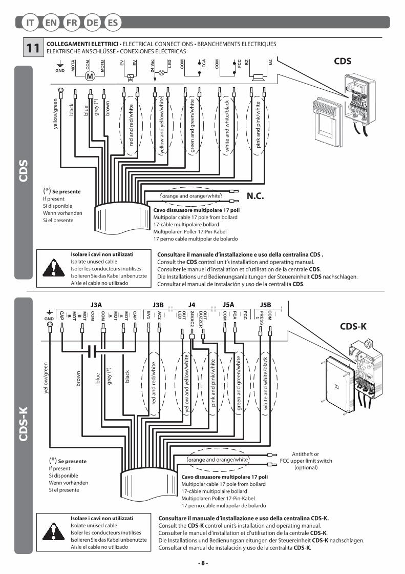
COLLEGAMENTI ELETTRICI • ELECTRICAL CONNECTIONS • BRANCHEMENTS ELECTRIQUESELEKTRISCHE ANSCHLÜSSE • CONEXIONES ELÉCTRICAS11
Isolare i cavi non utilizzati
Isolate unused cableIsoler les conducteurs inutilisésIsolieren Sie das Kabel unbenutzteAísle el cable no utilizado
Isolare i cavi non utilizzati
Isolate unused cableIsoler les conducteurs inutilisésIsolieren Sie das Kabel unbenutzteAísle el cable no utilizado
N.C.
MO
TB
MO
TB
MO
TA
MO
TA
CO
M
CO
M
CAP
CA
P
EV1
AC
2
GND
PRESS1
CO
M
OU
T LED
OU
T B
UZZER
24VAC
2
J3A J5BJ4
FCA
CO
M
FCC
J5A
brow
n
yello
w/g
reen
bla
ck
gre
y (*
)
blue
red
and
red/
whi
te
yel
low
and
yel
low
/whi
te
whi
te a
nd w
hite
/bla
ck
gree
n an
d gr
een/
whi
te
orange and orange/white
pin
k an
d pi
nk/w
hite
J3B
Antitheft or FCC upper limit switch
(optional)(*) Se presente
If presentSi disponibleWenn vorhandenSi el presente
(*) Se presente
If presentSi disponibleWenn vorhandenSi el presente
Cavo dissuasore multipolare 17 poli
Multipolar cable 17 pole from bollard17-câble multipolaire bollardMultipolaren Poller 17-Pin-Kabel17 perno cable multipolar de bolardo
Cavo dissuasore multipolare 17 poli
Multipolar cable 17 pole from bollard17-câble multipolaire bollardMultipolaren Poller 17-Pin-Kabel17 perno cable multipolar de bolardo
Consultare il manuale d’installazione e uso della centralina CDS .
Consult the CDS control unit’s installation and operating manual. Consulter le manuel d’installation et d’utilisation de la centrale CDS.Die Installations und Bedienungsanleitungen der Steuereinheit CDS nachschlagen.Consultar el manual de instalación y uso de la centralita CDS.
Consultare il manuale d’installazione e uso della centralina CDS-K.
Consult the CDS-K control unit’s installation and operating manual. Consulter le manuel d’installation et d’utilisation de la centrale CDS-K.Die Installations und Bedienungsanleitungen der Steuereinheit CDS-K nachschlagen.Consultar el manual de instalación y uso de la centralita CDS-K.
CDS
CDS-K
CDS
CDS-
KIT EN FR DE ES
- 9 -
1 2
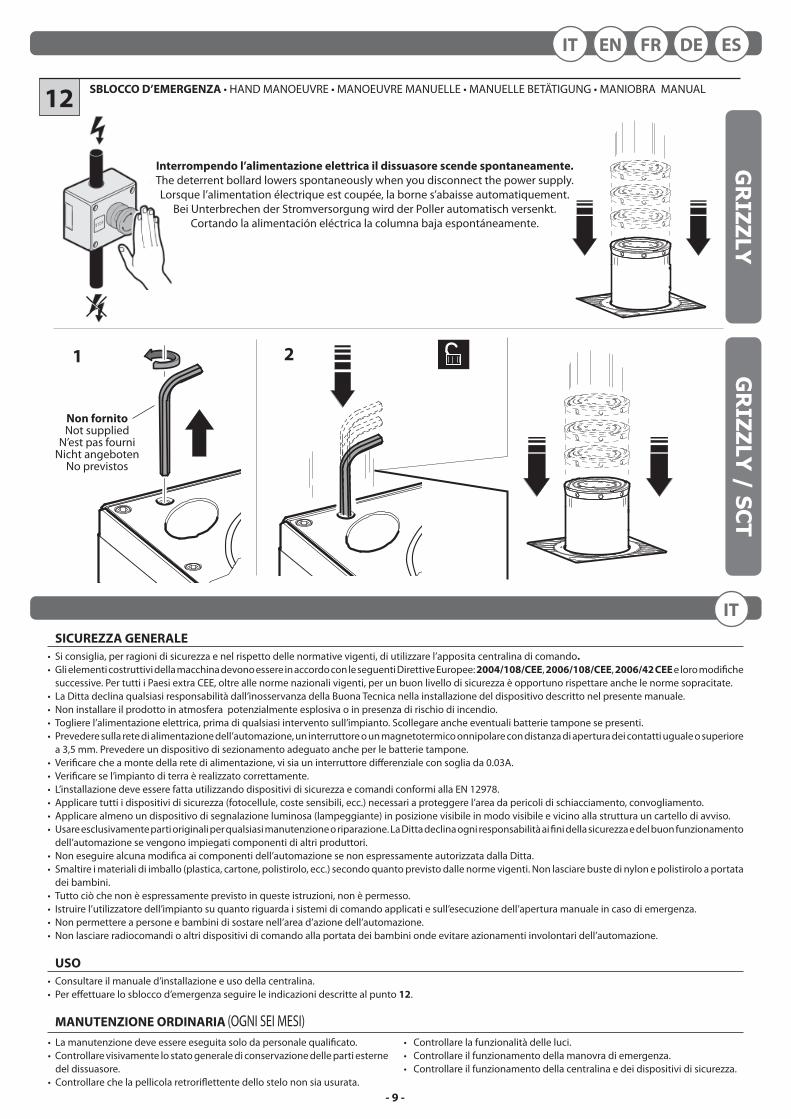
SBLOCCO D’EMERGENZA • HAND MANOEUVRE • MANOEUVRE MANUELLE • MANUELLE BETÄTIGUNG • MANIOBRA MANUAL
Interrompendo l’alimentazione elettrica il dissuasore scende spontaneamente.
The deterrent bollard lowers spontaneously when you disconnect the power supply.Lorsque l’alimentation électrique est coupée, la borne s’abaisse automatiquement.
Bei Unterbrechen der Stromversorgung wird der Poller automatisch versenkt.Cortando la alimentación eléctrica la columna baja espontáneamente.
12
Non fornitoNot supplied
N’est pas fourniNicht angeboten
No previstos
SICUREZZA GENERALE
• Si consiglia, per ragioni di sicurezza e nel rispetto delle normative vigenti, di utilizzare l’apposita centralina di comando.
• Gli elementi costruttivi della macchina devono essere in accordo con le seguenti Direttive Europee: 2004/108/CEE, 2006/108/CEE, 2006/42 CEE e loro modifi che successive. Per tutti i Paesi extra CEE, oltre alle norme nazionali vigenti, per un buon livello di sicurezza è opportuno rispettare anche le norme sopracitate.
• La Ditta declina qualsiasi responsabilità dall’inosservanza della Buona Tecnica nella installazione del dispositivo descritto nel presente manuale.• Non installare il prodotto in atmosfera potenzialmente esplosiva o in presenza di rischio di incendio.• Togliere l’alimentazione elettrica, prima di qualsiasi intervento sull’impianto. Scollegare anche eventuali batterie tampone se presenti.• Prevedere sulla rete di alimentazione dell’automazione, un interruttore o un magnetotermico onnipolare con distanza di apertura dei contatti uguale o superiore
a 3,5 mm. Prevedere un dispositivo di sezionamento adeguato anche per le batterie tampone.• Verifi care che a monte della rete di alimentazione, vi sia un interruttore diff erenziale con soglia da 0.03A.• Verifi care se l’impianto di terra è realizzato correttamente.• L’installazione deve essere fatta utilizzando dispositivi di sicurezza e comandi conformi alla EN 12978.• Applicare tutti i dispositivi di sicurezza (fotocellule, coste sensibili, ecc.) necessari a proteggere l’area da pericoli di schiacciamento, convogliamento.• Applicare almeno un dispositivo di segnalazione luminosa (lampeggiante) in posizione visibile in modo visibile e vicino alla struttura un cartello di avviso.• Usare esclusivamente parti originali per qualsiasi manutenzione o riparazione. La Ditta declina ogni responsabilità ai fi ni della sicurezza e del buon funzionamento
dell’automazione se vengono impiegati componenti di altri produttori.• Non eseguire alcuna modifi ca ai componenti dell’automazione se non espressamente autorizzata dalla Ditta.• Smaltire i materiali di imballo (plastica, cartone, polistirolo, ecc.) secondo quanto previsto dalle norme vigenti. Non lasciare buste di nylon e polistirolo a portata
dei bambini.• Tutto ciò che non è espressamente previsto in queste istruzioni, non è permesso.• Istruire l’utilizzatore dell’impianto su quanto riguarda i sistemi di comando applicati e sull’esecuzione dell’apertura manuale in caso di emergenza.• Non permettere a persone e bambini di sostare nell’area d’azione dell’automazione.• Non lasciare radiocomandi o altri dispositivi di comando alla portata dei bambini onde evitare azionamenti involontari dell’automazione.
USO
• Consultare il manuale d’installazione e uso della centralina.• Per eff ettuare lo sblocco d’emergenza seguire le indicazioni descritte al punto 12.
MANUTENZIONE ORDINARIA (OGNI SEI MESI)• La manutenzione deve essere eseguita solo da personale qualifi cato.• Controllare visivamente lo stato generale di conservazione delle parti esterne
del dissuasore.• Controllare che la pellicola retrorifl ettente dello stelo non sia usurata.
• Controllare la funzionalità delle luci.• Controllare il funzionamento della manovra di emergenza.• Controllare il funzionamento della centralina e dei dispositivi di sicurezza.
GR
IZZLY / SCTG
RIZZLY
ESDEFRENIT
IT
- 10 -
• Maintenance must be carried out by qualifi ed personnel only.• Visually check the overall state of wear and tear of the external parts of the
deterrent bollard.
• Make sure the rear-refl ecting fi lm is not worn.• Make sure the lights work.• Make sure the emergency manoeuvre is working properly.• Make sure the control unit and safety devices are in proper working order.
GENERAL SAFETY
• For safety reasons and to comply with current standards, we recommend using the control unit.• The construction components of this product must comply with the following European Directives: 2004/108/CEE, 2006/108/EEC, 2006/42 EEC and subsequent
amendments. As for all non-EEC countries, the above-mentioned standards as well as the current national standards should be respected in order to achieve a good safety level.
• The Company declines all responsibility for any consequences resulting from failure to observe Good Technical Practice when installing the device described in the present manual.
• Do not install the product in potentially explosive atmosphere or wherever there is a fi re risk.• Disconnect the electrical supply before carrying out any work on the installation. Also disconnect any buff er batteries, if fi tted.• Fit an omnipolar or magnetothermal switch on the mains power supply, having a contact opening distance equal to or greater than 3,5 mm. Also fi t an adequate
cut-out device for the buff er batteries.• Check that a diff erential switch with a 0.03A threshold is fi tted just before the power supply mains.• Check that earthing is carried out correctly.• Installation must be carried out using the safety devices and controls prescribed by the EN 12978 Standard.• Fit all the safety devices (photocells, electric edges etc.) which are needed to protect the area from any danger caused by squashing, conveying.• Position at least one luminous signal indication device (blinker) where it can be easily seen, and fi x a Warning sign next to the structure.• Only use original parts for any maintenance or repair operation. The Company declines all responsibility with respect to the automation safety and correct
operation when other producers’ components are used.• Do not modify the automation components, unless explicitly authorised by the Company.• Scrap packing materials (plastic, cardboard, polystyrene etc) according to the provisions set out by current standards. Keep nylon or polystyrene bags out of
children’s reach.• Anything which is not expressly provided for in the present instructions, is not allowed.• Instruct the product user about the control systems provided and the manual opening operation in case of emergency.• Do not allow persons or children to remain within the automation operation area.• Keep radio control or other control devices out of children’s reach, in order to avoid unintentional automation activation.
USE
• Consult the control unit’s installation and operating manual.• Follow the instructions given in point 12 to release in the case of emergency.
ROUTINE MAINTENANCE (EVERY 6 MONTHS)
SECURITE GENERALE
• Pour des raisons de sécurité et d’observation de la législation en vigueur, il est conseillé d’utiliser la centrale de commande. • Les éléments constituant la machine doivent être conformes aux Directives Européennes suivantes: 2004/108/CEE, 2006/108/CEE, 2006/42/CEE et modifi cations
successives. Pour tous les Pays extra-CEE, outre les normes nationales en vigueur, pour assurer un bon niveau de sécurité il est conseillé de respecter aussi les normes indiquées ci-haut.
• La Société décline toute responsabilité en cas de non respect des normes de Bonne Technique dans l’installation du dispositif décrit dans ce manuel.• Ne pas installer le produit dans une atmosphère potentiellement explosive ou en cas de risque d’incendie. • Couper l’alimentation électrique avant d’eff ectuer n’importe quelle intervention sur l’installation. Débrancher aussi les éventuelles batteries de secours. • Prévoir sur la ligne d’alimentation de l’automation un interrupteur ou un magnétothermique omnipolaire avec distance d’ouverture des contacts égale ou
supérieure à 3,5 mm. Prévoir un dispositif de disjonction adéquat aussi pour les batteries de secours. • Vérifi er qu’en amont de la ligne d’alimentation il y a un interrupteur diff érentiel avec seuil de 0,03A.• Contrôler si l’installation de terre est eff ectuée correctement. • L’installation doit être faite en utilisant des dispositifs de sécurité et des commandes conformes à la norme EN 12978.• Appliquer tous les dispositifs de sécurité (cellules photoélectriques, barres palpeuses etc.) nécessaires à protéger la zone des dangers d’écrasement, d’entraînement.• Appliquer au moins un dispositif de signalisation lumineuse (feu clignotant) en position visible, et un panneau d’avertissement près de la structure.• Utiliser exclusivement des pièces originales pour n’importe quel entretien ou réparation.• Ne pas eff ectuer des modifi cations aux composants de l’automation si non expressément autorisées par la Société.• Éliminer les matériaux d’emballage (plastique, carton, polystyrène etc.) selon les prescriptions des normes en vigueur. Ne pas laisser des enveloppes en nylon
et polystyrène à la portée des enfants.• Tout ce qui n’est pas expressément prévu dans ces instructions, est interdit.• Faire connaître à l’utilisateur de l’installation les systèmes de commande appliqués et l’exécution de l’ouverture manuelle en cas d’urgence.• Ne pas permettre à des personnes et à des enfants de stationner dans la zone d’action de l’automation.• Ne pas laisser des radio commandes ou d’autres dispositifs de commande à portée des enfants afi n d’éviter des actionnements involontaires de l’automation.
UTILISATION
• Consulter le manuel d’installation et d’utilisation de la centrale.• Pour eff ectuer la manoeuvre manuelle, suivez les indications du point 12.
ROUTINE MAINTENANCE (TOUS LES 6 MOIS)
• L’entretien doit être eff ectué seulement par un personnel qualifi é.• Vérifi er visuellement l’état général des parties externes de la borne.• Vérifi er que la pellicule rétro-réfl échissante n’est pas usée.
• Vérifi er le bon fonctionnement des lumières.• Vérifi er le fonctionnement de la manœuvre d’arrêt d’urgence.• Vérifi er le fonctionnement de la centrale et des dispositifs de sécurité.
EN
FR
- 11 -
ALLGEMEINE SICHERHEIT
• Aus Sicherheitsgründen und zum Einhalten der anwendbaren Gesetze wird empfohlen, die spezielle Steuereinheit von zu verwenden.• Die Bauteile der Maschine müssen den folgenden Europäischen Richtlinien entsprechen: 2004/108/EWG, 2006/108/EWG,2006/42 EWG und
nachfolgenden Änderungen. Für alle Länder außerhalb der EWG gilt: Außer den geltenden Landesvorschriften sollten aus Sicherheitsgründen auch die oben genannten Bestimmungen beachtet werden.
• Der Hersteller lehnt jede Verantwortung für Folgen ab, die durch nicht fachgerechte Installation der in diesem Handbuch beschriebenen Anlage entstehen.• Die Anlage darf nicht in explosionsgefährdeter oder feuergefährlicher Atmosphäre installiert werden.• Vor jedem Eingriff an der Anlage die Stromversorgung unterbrechen. Auch Puff erbatterien abklemmen, falls vorhanden.• Versehen Sie die Vorsorgungsleitung der Anlage mit einem Schalter oder allpoligen magnetthermischen Schutzschalter mit einem Kontaktabstand von
mindestens 3,5 mm. Auch für die Batterien muß eine geeignete Trennvorrichtung geschaff en werden.• Der Versorgungsleitung muß ein Fehlerstromschutzschalter mit einer Schwelle von 0.03A vorgeschaltet sein.• Prüfen Sie den Erdungsanschluß.• Die Installation muß mit Sicherheits- und Steuerungsvorrichtungen vorgenommen werden, die der Norm EN 12978 entsprechen.• Alle Sicherheitsvorrichtungen (Fotozellen, Sicherheitsleisten u. a.) anbringen, die verhindern, daß sich im Torbereich niemand quetscht, schneidet wird.• Mindestens eine Leuchtsignaleinrichtung (Blinklicht) an gut sichtbarer Stelle anbringen. Befestigen Sie in Nähe des Gestells ein Warnschild.• Für Wartungen und Reparaturen dürfen ausschließlich Originalteile verwenden. Der Hersteller lehnt jede Verantwortung für die Sicherheit und die
Funktionstüchtigkeit der Anlage ab, wenn Komponenten anderer Produzenten verwendet werden.• Es dürfen keine Umbauten an Anlagenkomponenten vorgenommen werden, die nicht ausdrücklich vom Hersteller genehmigt wurden.• Verpackungsmaterialien (Plastik, Karton, Polystyrol u. a.) sind nach den einschlägigen Vorschriften zu entsorgen. Nylon- oder Polystyroltüten dürfen nicht in
Reichweite von Kindern liegenbleiben.• Alles, was nicht ausdrücklich in dieser Anleitung genannt ist, ist untersagt.• Weisen Sie den Anlagenbetreiber in die vorhandenen Steuerungssysteme und die manuelle Toröff nung im Notfall ein.• Kindern oder Er wachsenen ist es nicht gestattet, im Aktionsbereich der Anlage zu verweilen.• Keine Fernbedienungen oder andere Steuerungsvorrichtungen in Reichweite von Kindern liegenlassen. Sie könnten die Anlage versehentlich in Gang
setzen.
BETRIEB
• Die Installations und Bedienungsanleitungen der Steuereinheit nachschlagen.• Für die manuelle Betätigung in Notfällen sind die Anleitungen unter Punkt 12 zu befolgen.
ORDENTLICHE WARTUNG (ALLE 6 MONATE)• Die Wartung hat ausschließlich durch Fachpersonal zu erfolgen.• Die Außenteile des Pollers einer allgemeinen Sichtkontrolle unterziehen,
um Beschädigungen festzustellen.• Kontrollieren, dass die Rückstrahlfolie nicht verschlissen ist.
• Die Funktionstüchtigkeit der Leuchten kontrollieren.• Kontrollieren, dass die manuelle Notfall-Manövriervorrichtung einwandfrei
funktioniert.• Die Funktionstüchtigkeit der Steuereinheit und der Sicherheitsvorrichtungen
überprüfen.
SEGURIDAD GENERAL
• Por razones de seguridad y para respetar las normas vigentes se aconseja utilizar la correspondiente centralita de control.• Los elementos constructivos de la máquina deben ser conformes a las siguientes Directivas Europeas: 2004/108/CEE, 2006/108/CEE, 2006/42 CEE y sucesivas
modifi caciones. Para todos los Países extra CEE, además de las normas nacionales vigentes, para asegurar un buen nivel de seguridad, es conveniente respetar también las normas citadas antes.
• La Empresa declina toda responsabilidad que derive de la inobservancia de la Buena Técnica en la instalación del dispositivo descrito en el presente manual.• No instalar el producto en atmósfera potencialmente explosiva o en presencia de riesgo de incendio.• Cortar el suministro de corriente antes de efectuar cualquier intervención en la instalación. Desconectar también eventuales baterías tampón.• Prever, en la red de alimentación del automatismo, un interruptor o un magnetotérmico omnipolar con una distancia de abertura de los contactos igual o
superior a 3,5 mm. Prever un dispositivo de seccionamiento adecuado también para las baterías tampón.• Verifi car que, antes de la red de alimentación, haya un interruptor diferencial con un umbral de 0,03 A.• Verifi car si la toma de tierra ha sido realizada correctamente.• La instalación debe realizarse utilizando dispositivos de seguridad y mandos conformes a la EN 12978.• Aplicar todos los dispositivos de seguridad (fotocélulas, barras sensibles, etc.) necesarios para proteger el área contra el peligro de aplastamiento,
transporte.• Aplicar, al menos, un dispositivo de señalización luminosa (luz intermitente) en posición visible y fi jar a la estructura un cartel de aviso.• Usar exclusivamente partes originales al realizar cualquier operación de mantenimiento o reparación. La Empresa declina toda responsabilidad,
a efectos de la seguridad y del buen funcionamiento del automatismo, si se emplean componentes de otros fabricantes.• No modifi car ningún componente del automatismo si antes no se ha sido expresamente autorizado por la Empresa.• Eliminar los materiales de embalaje (plástico, cartón, poliestireno, etc.) según lo previsto por las normas vigentes. No dejar bolsas de nylon
o poliestireno al alcance de los niños.• Todo lo que no está expresamente previsto en estas instrucciones no está permitido.• Instruir al usuario del equipo sobre los sistemas de mando aplicados y sobre la ejecución de la apertura manual en caso de emergencia.• No permitir que personas adultas o niños estacionen en el campo de acción del automatismo.• No dejar radiomandos u otros dispositivos de mando al alcance de los niños, para evitar el accionamiento involuntario del automatismo.
USO
• Consultar el manual de instalación y uso de la centralita.• Para efectuar el desbloqueo de emergencia seguir las indicaciones del punto 12.
MANTENIMIENTO ORDINARIO (CADA 6 MESES)• El mantenimiento debe ser efectuado sólo por personal cualifi cado.• Comprobar visualmente el estado general de las partes externas del disuasor.• Comprobar que la película retrorrefl ectora no está gastada.
• Comprobar la funcionalidad de las luces.• Comprobar el funcionamiento de la maniobra de emergencia.• Comprobar el funcionamiento de la centralita y de los dispositivos de seguridad.
DE
ES
INSTALLATOREINSTALLERINSTALLATEURINSTALLATEURINSTALATOR
cod.
035
717-
A r
ev. 0
07 d
ate
21-0
7-20
16