Embed Size (px)
Citation preview

GS3 Greenhouse Sensor 2365 NE Hopkins Ct / Pullman, WA 99163 USA Volumetric Water Content, Electrical Conductivity, and Temperature
For support contact us via email at [email protected] or call us at 1.509.332.5600 between 7AM to 5PM PST
1
APPLICATIONS
Greenhouse substrate monitoring.
Volumetric water content measurement.
Soil/Substrate water balance.
Irrigation management.
Electrical Conductivity measurement.
Salt management.
Fertilizer movement.
Soil/Substrate temperature measurement.
Modeling processes that are affected by
temperature.
DESCRIPTION
The Decagon GS3 sensor is an accurate tool for
monitoring electrical conductivity, volumetric water
content, and temperature in soil and soilless
substrates. All three measurements are made
independently. As with all ECH2O sensors, the GS3
determines volumetric water content (VWC) by
measuring the dielectric constant (εa) of the medium
using capacitance/frequency domain technology.
The sensor uses a 70 MHz frequency, which
minimizes textural and salinity effects, making the
GS3 accurate in most soilless substrates. The GS3
measures temperature using an onboard thermistor,
and electrical conductivity using a stainless steel
electrode array.
AUDIENCE
Decagon provides the information in this integrators
guide to help GS3 customers establish
communication between these sensors and their
data acquisition equipment or field data loggers.
Customers using data loggers that support SDI-12
sensor communications should consult the user's
manual for their data logger. These sensors are fully
integrated into Decagon's system of plug-and-play
sensors, cellular-enabled data loggers, and data
analysis software.
ADVANTAGES
Digital sensor communicates three
measurements over a serial interface.
2-probe EC measurement.
Robust thermistor for accurate temperature
measurements.
Low input voltage requirements.
Low power design supports battery-operated
data loggers.
Robust epoxy encapsulation and stainless
steel needles to resist corrosive environments.
Supports SDI-12 or DDI-Serial 1-wire serial
communications protocols.
Modern design optimized for low-cost sensing.
MEASUREMENT SPECIFICATIONS
Volumetric Water Content Temperature Electrical Conductivity Accuracy ±1 εa (unitless) from 1 – 40 εa
±15% from 40 – 80 εa
Generic calibration equation:
± 0.03 m3/m3 (± 3% VWC)
Medium Specific Calibration:
± 0.02 m3/m3 (± 2% VWC)
± 1°C ± 10% from 0 to 10 mS/cm (dS/m)
user calibration required above:
10 mS/cm (dS/m)
Resolution 0.1 εa (unitless) from 1 – 20 εa
<0.75 εa from 20 – 80 εa
0.2% VWC from 0% – 40% VWC
0.1% VWC from 40% – 100% VWC
0.1°C 0.001 mS/cm (dS/m)
Range 1 εa – 80 εa - 40°C to + 50°C 0 – 23 dS/m
GS3 Integrator Guide R04
For support contact us via email at [email protected] or call us at 1.509.332.5600 between 7AM to 5PM PST 2
PHYSICAL CHARACTERISTICS
SENSOR IMAGE
SENSOR NAME GS3 Greenhouse Sensor
DIMENSIONS 9.3 cm X 6.5 cm X 2.4 cm
CABLE LENGTH* 5 meters * Custom cable lengths are available for an additional cost.
ELECTRICAL AND TIMING CHARACTERISTICS
PARAMETER MIN TYP MAX UNITS
Supply Voltage (VCC) to GND 3.6 15 V
Digital Input Voltage (logic high) 2.6 3 3.9 V
Digital Input Voltage (logic low) -0.3 0 0.75 V
Current Drain (during measurement) 0.5 3 30 mA
Current Drain (while asleep) 0.03 mA
Operating Temperature Range -40 50 °C
Power Up Time (DDI-Serial) 100 mS
Power Up Time (SDI-12) 100 150 200 mS
Measurement duration 150 200 mS
Cable Capacitance / meter 250 pF
Cable Resistance / meter 35 mΩ
EQUIVALENT CIRCUIT DIAGRAM CONNECTION TYPES
NOTE: This is a low impedance variant of the recommended SDI-12
Specification. This allows up to 62 sensors to be maintained on a bus.
PIGTAIL CABLE
STEREO CABLE
Data
Power
Ground
Data
Power
Ground

GS3 Integrator Guide R04
For support contact us via email at [email protected] or call us at 1.509.332.5600 between 7AM to 5PM PST 3
! SAFETY PRECAUTIONS Our probes are built to the highest standards but misuse or improper protection or improper installation
may break your sensor and possibly void the manufacturer’s warranty. Before integrating your sensors
into your sensor network, make sure you have followed the recommended installation instructions and
have the proper protections in place to safeguard your sensor from damaging interference.
LIGHTNING AND SURGE PROTECTION
Probes have built in circuitry that protects them against common surge conditions. Installations in
lightning-prone areas, however, require special precautions, especially when probes are connected to a
well-grounded third party logger.
Visit our website and read the following application note for more information:
Lightning Surge Suppression And Standard Grounding Practices
POWER AND GROUNDING
Older sensor versions start measurements as soon as they are powered. For older sensors, ensure that
there is sufficient power to support the maximum sensor current drain for all the sensors on the bus
simultaneously.
Our sensor protection circuitry may be insufficient if your data logger is improperly powered or grounded.
Refer to your data logger’s installation instructions. Improper grounding may affect the sensor output as
well as the sensor performance.
For Decagon loggers, visit our website and read the following article for more information:
Lightning Surge Suppression And Standard Grounding Practices
CABLE PROBLEMS
Cable problems can lead to severed cables or disconnected sensors. Rodent damage, driving over sensor
cables, tripping over the cable, not leaving enough cable slack during installation or poor sensor wiring
connections are just some of many factors that can cause cabling issues.
GS3 Integrator Guide R04
For support contact us via email at [email protected] or call us at 1.509.332.5600 between 7AM to 5PM PST 4
SENSOR COMMUNICATION TYPES Decagon digital sensors feature a 1-wire serial interface for communicating sensor measurements. The
sensor supports two different protocols: SDI-12 and DDI-Serial. Both interfaces are documented in this
guide. Each protocol has advantages and implementation challenges. There are differences in voltage
levels, logic levels, and signal timing for each protocol. Please contact Decagon with your specific
requirements if the protocol choice for your application is not obvious.
SDI-12 INTRODUCTION
SDI-12 is a standards-based protocol for interfacing sensors to data loggers and data acquisition
equipment. Multiple sensors with unique addresses can share a common 3-wire bus (power, ground, and
data). Two-way communication between the sensor and logger are possible by sharing the data line for
transmit and receive as defined by the standard. Sensor measurements are triggered by protocol
command.
DDI-SERIAL INTRODUCTION
The DDI-Serial protocol is the method used by the Decagon's family of data loggers for collecting data from
the sensor. This protocol uses the data line configured to transmit data from the sensor to the receiver
only (simplex). Typically the receive side is a microprocessor UART or a general-purpose IO pin using a "bit-
bang" method to receive data. Sensor measurements are triggered by applying power to the sensor.
INTERFACING THE SENSOR TO A PC
The serial signals and protocols supported by the sensor require some type of interface hardware to be
compatible with the serial port found on most personal computers (or USB-to-Serial adapters). There are
several SDI-12 interface adapters available in the marketplace; however, Decagon has not tested any of
these interfaces and cannot make a recommendation of which adapters work with Decagon sensors.
Decagon's Em50 data logger and ProCheck hand-held both are able to operate as a computer-to-sensor
interface for making on-demand sensor measurements.
GS3 Integrator Guide R04
For support contact us via email at [email protected] or call us at 1.509.332.5600 between 7AM to 5PM PST 5
SDI-12 COMMUNICATION SDI-12 is a common bus communication protocol that allows you to connect multiple sensors to a
common data line. The SDI-12 protocol requires a unique alpha numeric sensor address for each sensor
on the bus so that a data logger can send and receive readings to specific sensors.
Visit www.sdi-12.org to download the latest SDI-12 Specification or find out more information about the
standard.
DECAGON’S SDI-12 IMPLEMENTATION
Decagon’s sensors use a low impedance variant of the SDI-12 standard sensor circuit (see the Equivalent
Circuit Diagram). This allows for up to 62 sensors to be connected onto the bus at one time instead of the
10 that is stated in the standard. Keep in mind that the more sensors you have on a bus, the more
difficult it will be to isolate and remove the faulty sensor and restore communication to the remaining
sensors on your SDI-12 bus.
Out of the factory, all Decagon sensors start with SDI-12 address zero and print out the DDI-Serial string
during the power up time specified in the Electrical and Timing Characteristics section (See the start up
sequence diagram in the DDI-Serial section for a detailed diagram). This can be interpreted by non-
Decagon SDI-12 sensors as a pseudo-break condition followed by a random series of bits. To circumvent
this issue, GS3 sensors with firmware version 3.37 and newer omit the DDI-Serial string when their SDI-12
address is non-zero. Simply changing the sensor addresses on the SDI-12 bus to non-zero values will
prevent any race conditions on the data line during sensor power up.
After the power up time, our sensors are fully compatible with all the commands listed in the SDI-12
Specification v1.3 except for the continuous measurement commands (aR0 – aR9 and aRC0 – aRC9).
SENSOR BUS CONSIDERATIONS
An SDI-12 bus isn’t something you can set up and just walk away. Sensor buses require regular checking,
sensor upkeep, and sensor trouble-shooting. If one sensor goes down, that may take down the whole bus
even if the remaining sensors are functioning normally. Power cycling the SDI-12 bus when a sensor is
failing is okay but we do not recommend scheduling power cycling events on an SDI-12 bus more than
once or twice a day.
Many factors influence the effectiveness of your bus configuration and many questions should be
answered: How often should data be checked? How is the data delivered to the end user? How do I isolate
a faulty sensor?
Visit our website and read our application note and view our virtual seminars on Best Practices for SDI-12
Sensor Networks.
GS3 Integrator Guide R04
For support contact us via email at [email protected] or call us at 1.509.332.5600 between 7AM to 5PM PST 6
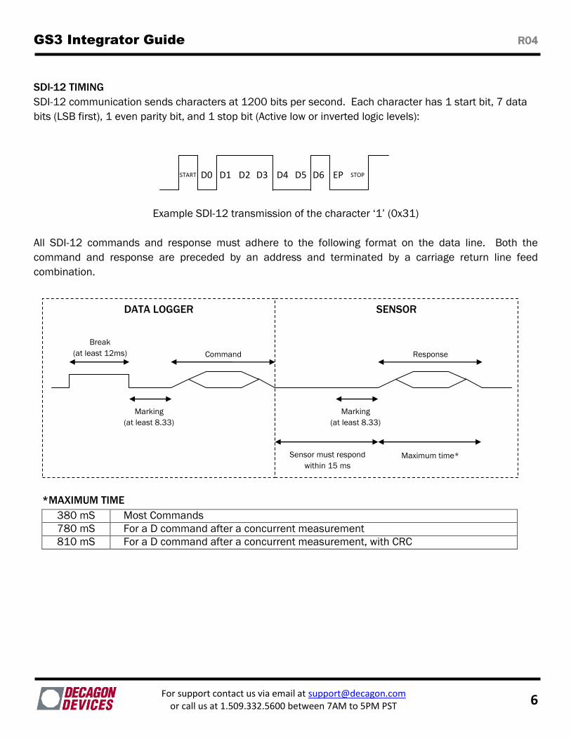
SDI-12 TIMING
SDI-12 communication sends characters at 1200 bits per second. Each character has 1 start bit, 7 data
bits (LSB first), 1 even parity bit, and 1 stop bit (Active low or inverted logic levels):
Example SDI-12 transmission of the character ‘1’ (0x31)
All SDI-12 commands and response must adhere to the following format on the data line. Both the
command and response are preceded by an address and terminated by a carriage return line feed
combination.
*MAXIMUM TIME
380 mS Most Commands
780 mS For a D command after a concurrent measurement
810 mS For a D command after a concurrent measurement, with CRC
DATA LOGGER SENSOR
Break
(at least 12ms) Command Response
Sensor must respond
within 15 ms
Maximum time*
Marking
(at least 8.33)
ms)
Marking
(at least 8.33)
ms)
START STOP D0 EP D3 D6 D2 D5 D1 D4
GS3 Integrator Guide R04
For support contact us via email at [email protected] or call us at 1.509.332.5600 between 7AM to 5PM PST 7
COMMON SDI-12 COMMANDS
Below is a list of common SDI-12 commands that are often used in an SDI-12 system and the
corresponding responses from our sensors:
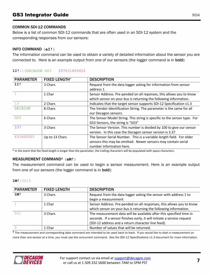
INFO COMMAND (aI!)
The information command can be used to obtain a variety of detailed information about the sensor you are
connected to. Here is an example output from one of our sensors (the logger command is in bold):
1I!113DECAGON GS3 337631800001
PARAMETER FIXED LENGTH* DESCRIPTION 1I! 3 Chars Request from the data logger asking for information from sensor
address 1. 1 1 Char Sensor Address. Pre-pended on all reponses, this allows you to know
which sensor on your bus is returning the following information. 13 2 Chars Indicates that the target sensor supports SDI-12 Specification v1.3 DECAGON 8 Chars The Vendor Identification String. The parameter is the same for all
our Decagon sensors. GS3 6 Chars The Sensor Model String. This string is specific to the sensor type. For
GS3 Sensors, the string is “GS3” 337 3 Chars The Sensor Version. This number is divided by 100 to give our sensor
version. In this case the Decagon sensor version is 3.37 631800001 Up to 13 Chars The Sensor Serial Number. This is a variable length field. For older
sensors this may be omitted. Newer sensors may contain serial number information here.
* In the event that the fixed length is longer than the parameter, the trailing characters will be populated with space characters.
MEASUREMENT COMMAND† (aM!)
The measurement command can be used to begin a sensor measurement. Here is an example output
from one of our sensors (the logger command is in bold):
1M!10013
PARAMETER FIXED LENGTH DESCRIPTION 1M! 3 Chars Request from the data logger asking the sensor with address 1 to
begin a measurement 1 1 Char Sensor Address. Pre-pended on all responses, this allows you to know
which sensor on your bus is returning the following information. 001 3 Chars The measurement data will be available after this specified time in
seconds. If a sensor finishes early, it will initiate a service request (SDI-12 address and a return character line feed).
3 1 Char Number of values that will be returned. † The measurement and corresponding data command are intended to be used back to back. If you would like to start a measurement on
more than one sensor at a time, you must use the concurrent command. See the SDI-12 Specifications v1.3 document for more information.
GS3 Integrator Guide R04
For support contact us via email at [email protected] or call us at 1.509.332.5600 between 7AM to 5PM PST 8
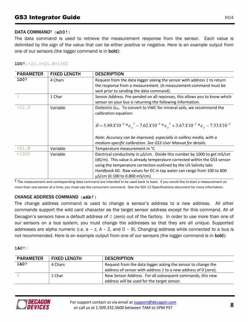
DATA COMMAND† (aD0!)
The data command is used to retrieve the measurement response from the sensor. Each value is
delimited by the sign of the value that can be either positive or negative. Here is an example output from
one of our sensors (the logger command is in bold):
1D0!1+22.0+21.8+1302
PARAMETER FIXED LENGTH DESCRIPTION 1D0! 4 Chars Request from the data logger asking the sensor with address 1 to return
the response from a measurement. (A measurement command must be sent prior to sending the data command).
1 1 Char Sensor Address. Pre-pended on all reponses, this allows you to know which sensor on your bus is returning the following information.
+22.0 Variable Dielectric (εa). To convert to VWC for mineral soils, we recommend the calibration equation:
222436 1053.7*1067.3*1062.7*1089.5 XXXX aaa
Note: Accuracy can be improved, especially in soilless media, with a medium-specific calibration. See GS3 User Manual for details.
+21.8 Variable Temperature measurement in °C +1302 Variable Electrical conductivity in µS/cm. Divide this number by 1000 to get mS/cm
(dS/m). This value is already temperature corrected within the GS3 sensor using the temperature correction outlined by the US Salinity labs Handbook 60. Raw values for EC in tap water can range from 100 to 800 µS/cm (0.100 to 0.800 mS/cm).
† The measurement and corresponding data command are intended to be used back to back. If you would like to start a measurement on
more than one sensor at a time, you must use the concurrent command. See the SDI-12 Specifications document for more information.
CHANGE ADDRESS COMMAND (aAb!)
The change address command is used to change a sensor’s address to a new address. All other
commands support the wild card character as the target sensor address except for this command. All of
Decagon’s sensors have a default address of 0 (zero) out of the factory. In order to use more than one of
our sensors on a bus system, you must change the addresses so that they are all unique. Supported
addresses are alpha numeric (i.e. a – z, A – Z, and 0 – 9). Changing address while connected to a bus is
not recommended. Here is an example output from one of our sensors (the logger command is in bold):
1A0!0
PARAMETER FIXED LENGTH DESCRIPTION 1A0! 4 Chars Request from the data logger asking the sensor to change the
address of sensor with address 1 to a new address of 0 (zero). 0 1 Char New Sensor Address. For all subsequent commands, this new
address will be used for the target sensor.
GS3 Integrator Guide R04
For support contact us via email at [email protected] or call us at 1.509.332.5600 between 7AM to 5PM PST 9
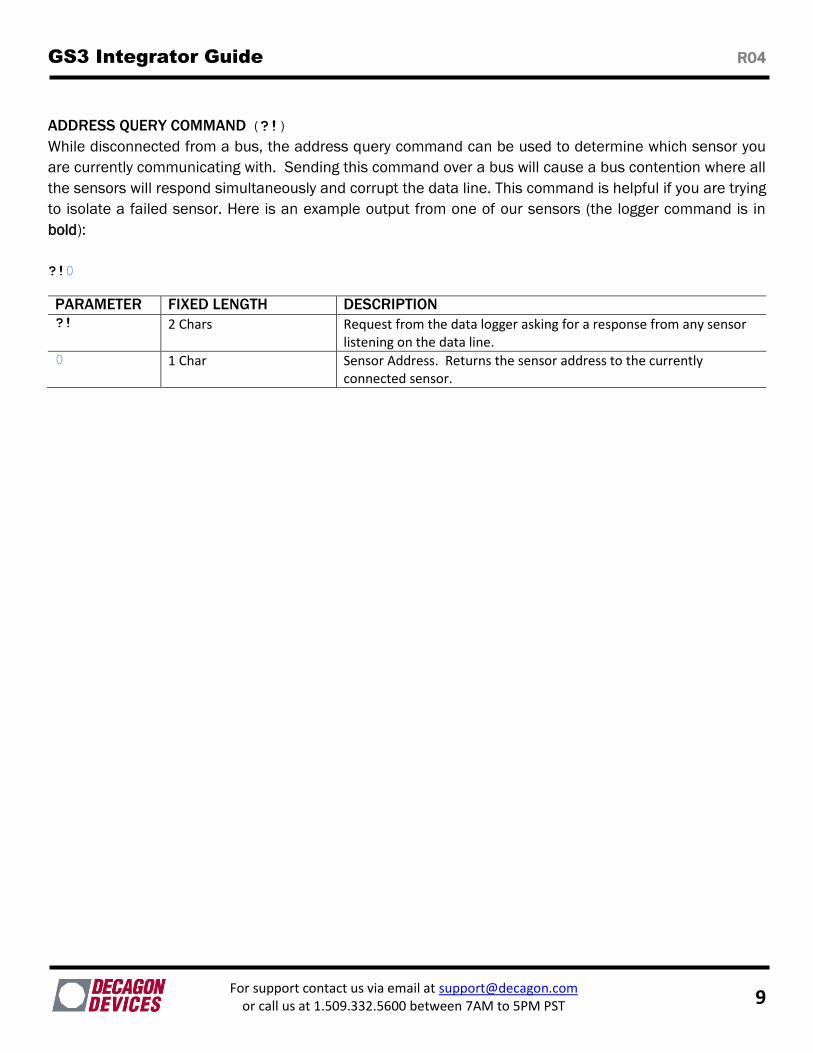
ADDRESS QUERY COMMAND (?!)
While disconnected from a bus, the address query command can be used to determine which sensor you
are currently communicating with. Sending this command over a bus will cause a bus contention where all
the sensors will respond simultaneously and corrupt the data line. This command is helpful if you are trying
to isolate a failed sensor. Here is an example output from one of our sensors (the logger command is in
bold):
?!0
PARAMETER FIXED LENGTH DESCRIPTION ?! 2 Chars Request from the data logger asking for a response from any sensor
listening on the data line. 0 1 Char Sensor Address. Returns the sensor address to the currently
connected sensor.
GS3 Integrator Guide R04
For support contact us via email at [email protected] or call us at 1.509.332.5600 between 7AM to 5PM PST 10
DDI-SERIAL COMMUNICATION The DDI-Serial communications protocol is ideal for systems that have dedicated serial signaling lines for
each sensor or use a multiplexer to handle multiple sensors. The serial communications are compatible
with many TTL serial implementations that support active-high logic levels using 0-3.6 volts signal levels.
When the sensor is first powered, it automatically makes measurements of the integrated transducers
then outputs a response over the data line. Systems using this protocol control the sensor excitation to
initiate data transfers from the sensor. This protocol is subject to change as Decagon improves and
expands our line of digital sensors and data loggers.
NOTE: Out of the factory, all Decagon sensors start with SDI-12 address zero and print out the startup
string when powered cycled. On GS3 sensors with firmware version 3.37 and newer the start up string is
omitted when the address is non-zero.
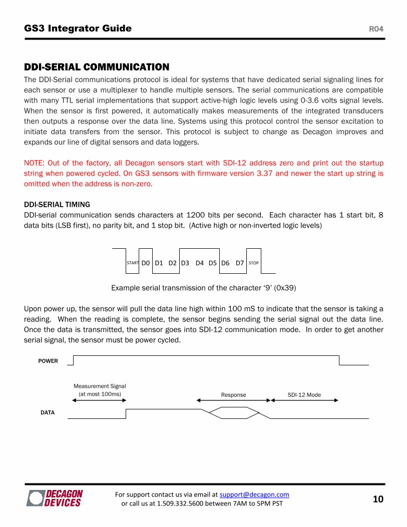
DDI-SERIAL TIMING
DDI-serial communication sends characters at 1200 bits per second. Each character has 1 start bit, 8
data bits (LSB first), no parity bit, and 1 stop bit. (Active high or non-inverted logic levels)
Example serial transmission of the character ‘9’ (0x39)
Upon power up, the sensor will pull the data line high within 100 mS to indicate that the sensor is taking a
reading. When the reading is complete, the sensor begins sending the serial signal out the data line.
Once the data is transmitted, the sensor goes into SDI-12 communication mode. In order to get another
serial signal, the sensor must be power cycled.
START STOP D0 D7 D3 D6 D2 D5 D1 D4
Response SDI-12 Mode
POWER
Measurement Signal
(at most 100ms)
DATA
GS3 Integrator Guide R04
For support contact us via email at [email protected] or call us at 1.509.332.5600 between 7AM to 5PM PST 11
Note: Sometimes the signaling from the sensor can confuse typical microprocessor UARTs. The sensor
holds the data line low while it takes measurements. It raises the line high to signal the logger that it will
send a measurement as documented above. Then the sensor may take some additional measurements
before starting to clock out the first data byte starting with a typical start bit (low). Once the first start bit is
sent, typical serial timing is valid; however, the signal transitions before this point are not serial signaling
and may be misinterpreted by the UART.
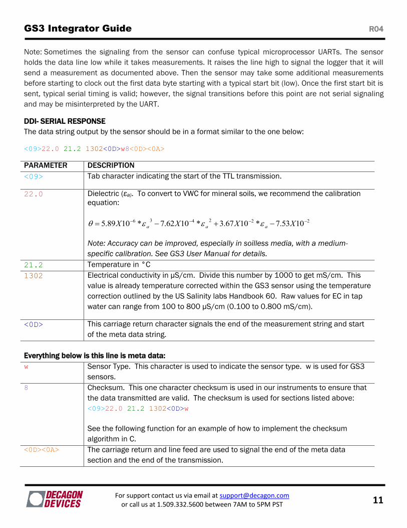
DDI- SERIAL RESPONSE
The data string output by the sensor should be in a format similar to the one below:
<09>22.0 21.2 1302<0D>w8<0D><0A>
PARAMETER DESCRIPTION
<09> Tab character indicating the start of the TTL transmission.
22.0 Dielectric (εa). To convert to VWC for mineral soils, we recommend the calibration
equation:
222436 1053.7*1067.3*1062.7*1089.5 XXXX aaa
Note: Accuracy can be improved, especially in soilless media, with a medium-
specific calibration. See GS3 User Manual for details.
21.2 Temperature in °C
1302 Electrical conductivity in µS/cm. Divide this number by 1000 to get mS/cm. This
value is already temperature corrected within the GS3 sensor using the temperature
correction outlined by the US Salinity labs Handbook 60. Raw values for EC in tap
water can range from 100 to 800 µS/cm (0.100 to 0.800 mS/cm).
<0D> This carriage return character signals the end of the measurement string and start
of the meta data string.
Everything below is this line is meta data:
w Sensor Type. This character is used to indicate the sensor type. w is used for GS3
sensors.
8 Checksum. This one character checksum is used in our instruments to ensure that
the data transmitted are valid. The checksum is used for sections listed above:
<09>22.0 21.2 1302<0D>w
See the following function for an example of how to implement the checksum
algorithm in C.
<0D><0A> The carriage return and line feed are used to signal the end of the meta data
section and the end of the transmission.
GS3 Integrator Guide R04
For support contact us via email at [email protected] or call us at 1.509.332.5600 between 7AM to 5PM PST 12
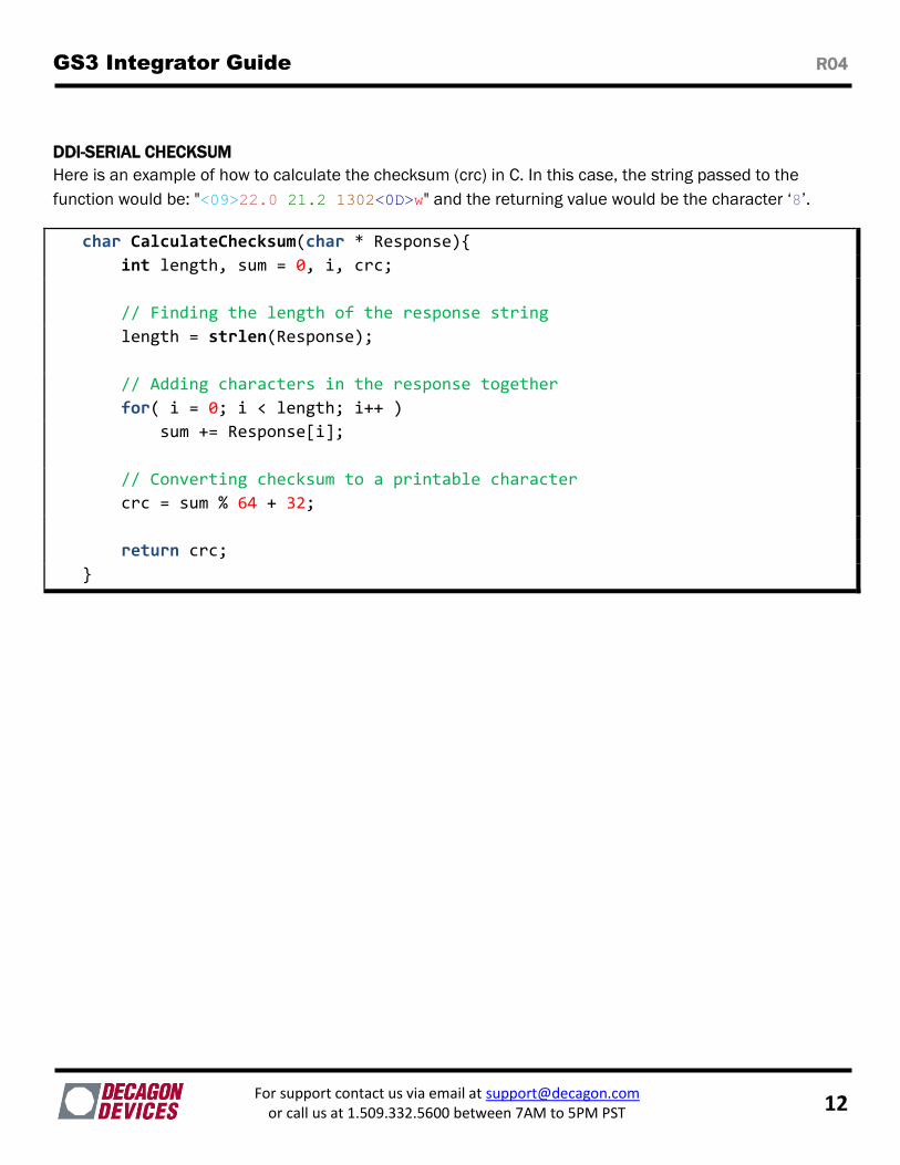
DDI-SERIAL CHECKSUM
Here is an example of how to calculate the checksum (crc) in C. In this case, the string passed to the
function would be: "<09>22.0 21.2 1302<0D>w" and the returning value would be the character ‘8’.
char CalculateChecksum(char * Response)
int length, sum = 0, i, crc;
// Finding the length of the response string
length = strlen(Response);
// Adding characters in the response together
for( i = 0; i < length; i++ )
sum += Response[i];
// Converting checksum to a printable character
crc = sum % 64 + 32;
return crc;