Embed Size (px)
Citation preview

H.264 Network DVR User ManualProduct: DMR40DVD, DMR41DVD, DMR42DVD
Please read this manual before using your recorder, and always follow the instructions for safety and proper use. Save this manual for future reference.
DMR40-41-42DVD_RM

ii www.supercircuits.com
WARNING! Do not expose this product to liquids. Objects filled with liquids, such as vases, should be
kept away.
CAUTION
This is a Safety Class 1 Product (provided with a protective earth ground incorporated in the power cord). The mains plug must be inserted in a electrical outlet provided with a protective earth contact. A break in the protective conductor inside or outside of the product can be dangerous. Tampering with the protective earth ground circuit is prohibited.
This product complies with radio interference requirements.
LEGAL NOTICE Supercircuits products are designed to meet safety and performance standards with the use of specific Supercircuits authorized accessories. Supercircuits disclaims liability associated with the use of non-Supercircuits authorized accessories.
The recording, transmission, or broadcast of any person’s voice without their consent or a court order is strictly prohibited by law.
Supercircuits makes no representations concerning the legality of certain product applications such as the making, transmission, or recording of video and/or audio signals of others without their knowledge and/or consent. We encourage you to check and comply with all applicable local, state, and federal laws and regulations before engaging in any form of surveillance or any transmission of radio frequencies.
Other trademarks and trade names may be used in this document to refer to either the entities claiming the marks and names or their products. Supercircuits, Inc. disclaims any proprietary interest in trademarks and trade names other than its own.
No part of this document may be reproduced or distributed in any form or by any means without the express written permission of Supercircuits, Inc.
© 2010 Supercircuits, Inc. All rights reserved.11000 N. Mopac Expressway, Building 300, Austin, TX 78759 Sales/Support: 1.800.335.9777 | Fax: 1.866.267.9777

iiiH.264 Network DVR User Manual
Table of Contents
SECTION 1 Product Description . . . . . . . . . . . . . . . . . . . . . . . . . . . . . . . . . . . . . . . . . . . . . . 11 .1 Features . . . . . . . . . . . . . . . . . . . . . . . . . . . . . . . . . . . . . . . . . . . . . . . . . . . 11 .2 Package Contents . . . . . . . . . . . . . . . . . . . . . . . . . . . . . . . . . . . . . . . . . . . 2
SECTION 2 Front and Rear Panel Controls and Indicators . . . . . . . . . . . . . . . . . . . . . . . . . . 32 .1 Front Panel . . . . . . . . . . . . . . . . . . . . . . . . . . . . . . . . . . . . . . . . . . . . . . . . . 3
2 .1 .1 LED Indicators: . . . . . . . . . . . . . . . . . . . . . . . . . . . . . . . . . . . . . . . . . . 32 .1 .2 Buttons . . . . . . . . . . . . . . . . . . . . . . . . . . . . . . . . . . . . . . . . . . . . . . . . 3
2 .2 Rear Panel . . . . . . . . . . . . . . . . . . . . . . . . . . . . . . . . . . . . . . . . . . . . . . . . . 5SECTION 3 Connections and Setup . . . . . . . . . . . . . . . . . . . . . . . . . . . . . . . . . . . . . . . . . . . 7
3 .1 HDD installation . . . . . . . . . . . . . . . . . . . . . . . . . . . . . . . . . . . . . . . . . . . . . 73 .1 .1 HDD installation for DMR42DVD and DMR41DVD . . . . . . . . . . . . . . . 73 .1 .2 HDD installation for DMR40DVD . . . . . . . . . . . . . . . . . . . . . . . . . . . . 9
3 .2 Camera connection . . . . . . . . . . . . . . . . . . . . . . . . . . . . . . . . . . . . . . . . . 113 .2 .1 Regular Camera Connection . . . . . . . . . . . . . . . . . . . . . . . . . . . . . . . 113 .2 .2 Speed Dome camera RS485 cabling . . . . . . . . . . . . . . . . . . . . . . . . . 11
SECTION 4 DVR Software Usage . . . . . . . . . . . . . . . . . . . . . . . . . . . . . . . . . . . . . . . . . . . . 144 .1 Power on the DVR . . . . . . . . . . . . . . . . . . . . . . . . . . . . . . . . . . . . . . . . . . 144 .2 Menu tree* . . . . . . . . . . . . . . . . . . . . . . . . . . . . . . . . . . . . . . . . . . . . . . . . 144 .3 Menu operations keys . . . . . . . . . . . . . . . . . . . . . . . . . . . . . . . . . . . . . . . 154 .4 QUICK START menu . . . . . . . . . . . . . . . . . . . . . . . . . . . . . . . . . . . . . . . . . 16
4 .4 .1 STATUS . . . . . . . . . . . . . . . . . . . . . . . . . . . . . . . . . . . . . . . . . . . . . . . 164 .4 .2 RECORD . . . . . . . . . . . . . . . . . . . . . . . . . . . . . . . . . . . . . . . . . . . . . . 164 .4 .3 TIMER . . . . . . . . . . . . . . . . . . . . . . . . . . . . . . . . . . . . . . . . . . . . . . . . 174 .4 .4 DATE . . . . . . . . . . . . . . . . . . . . . . . . . . . . . . . . . . . . . . . . . . . . . . . . . 194 .4 .5 Setting the date and time . . . . . . . . . . . . . . . . . . . . . . . . . . . . . . . . . 21
4 .5 ADVANCE CONFIG . . . . . . . . . . . . . . . . . . . . . . . . . . . . . . . . . . . . . . . . . . 224 .5 .1 CAMERA menu . . . . . . . . . . . . . . . . . . . . . . . . . . . . . . . . . . . . . . . . 224 .5 .2 DETECTION . . . . . . . . . . . . . . . . . . . . . . . . . . . . . . . . . . . . . . . . . . . . 234 .5 .3 Alert . . . . . . . . . . . . . . . . . . . . . . . . . . . . . . . . . . . . . . . . . . . . . . . . . 254 .5 .4 Network . . . . . . . . . . . . . . . . . . . . . . . . . . . . . . . . . . . . . . . . . . . . . . 264 .5 .5 SNTP . . . . . . . . . . . . . . . . . . . . . . . . . . . . . . . . . . . . . . . . . . . . . . . . 294 .5 .6 DISPLAY . . . . . . . . . . . . . . . . . . . . . . . . . . . . . . . . . . . . . . . . . . . . . . 294 .5 .7 RECORD . . . . . . . . . . . . . . . . . . . . . . . . . . . . . . . . . . . . . . . . . . . . . . 304 .5 .8 REMOTE . . . . . . . . . . . . . . . . . . . . . . . . . . . . . . . . . . . . . . . . . . . . . . 314 .5 .9 PTZ camera setup . . . . . . . . . . . . . . . . . . . . . . . . . . . . . . . . . . . . . . . 32
4 .6 SYSTEM INFO . . . . . . . . . . . . . . . . . . . . . . . . . . . . . . . . . . . . . . . . . . . . . 33

iv www.supercircuits.com
TABLES OF CONTENTS
4 .6 .1 Setting the password . . . . . . . . . . . . . . . . . . . . . . . . . . . . . . . . . . . . 344 .7 EVENT INFO . . . . . . . . . . . . . . . . . . . . . . . . . . . . . . . . . . . . . . . . . . . . . . . 34
4 .7 .1 Quick Search . . . . . . . . . . . . . . . . . . . . . . . . . . . . . . . . . . . . . . . . . . 354 .7 .2 Event Search . . . . . . . . . . . . . . . . . . . . . . . . . . . . . . . . . . . . . . . . . . . 354 .7 .3 HDD INFO . . . . . . . . . . . . . . . . . . . . . . . . . . . . . . . . . . . . . . . . . . . . . 364 .7 .4 EVENT LOG . . . . . . . . . . . . . . . . . . . . . . . . . . . . . . . . . . . . . . . . . . . . 36
4 .8 BACKUP . . . . . . . . . . . . . . . . . . . . . . . . . . . . . . . . . . . . . . . . . . . . . . . . . . 374 .8 .1 USB BACKUP . . . . . . . . . . . . . . . . . . . . . . . . . . . . . . . . . . . . . . . . . . 384 .8 .2 DISK BACKUP (selected models) . . . . . . . . . . . . . . . . . . . . . . . . . . . 39
SECTION 5 Basic Operation . . . . . . . . . . . . . . . . . . . . . . . . . . . . . . . . . . . . . . . . . . . . . . . . 415 .1 Live page . . . . . . . . . . . . . . . . . . . . . . . . . . . . . . . . . . . . . . . . . . . . . . . . . 41
5 .1 .1 Recording icons . . . . . . . . . . . . . . . . . . . . . . . . . . . . . . . . . . . . . . . . 425 .2 Playback . . . . . . . . . . . . . . . . . . . . . . . . . . . . . . . . . . . . . . . . . . . . . . . . . . 425 .3 Key lock and unlock . . . . . . . . . . . . . . . . . . . . . . . . . . . . . . . . . . . . . . . . . 435 .4 Firmware upgrade . . . . . . . . . . . . . . . . . . . . . . . . . . . . . . . . . . . . . . . . . . 435 .5 Search . . . . . . . . . . . . . . . . . . . . . . . . . . . . . . . . . . . . . . . . . . . . . . . . . . . 44
SECTION 6 Local and Remote Operation . . . . . . . . . . . . . . . . . . . . . . . . . . . . . . . . . . . . . . 456 .1 Networking your DVR . . . . . . . . . . . . . . . . . . . . . . . . . . . . . . . . . . . . . . . 456 .2 Video Viewer software . . . . . . . . . . . . . . . . . . . . . . . . . . . . . . . . . . . . . . . 45
6 .2 .1 Install Video Viewer software . . . . . . . . . . . . . . . . . . . . . . . . . . . . . . 466 .2 .2 Network connection via LAN/WAN . . . . . . . . . . . . . . . . . . . . . . . . . . 466 .2 .3 Video Viewer displays . . . . . . . . . . . . . . . . . . . . . . . . . . . . . . . . . . . 476 .2 .4 Operations . . . . . . . . . . . . . . . . . . . . . . . . . . . . . . . . . . . . . . . . . . . . 496 .2 .5 E-Map features . . . . . . . . . . . . . . . . . . . . . . . . . . . . . . . . . . . . . . . . . 52
6 .3 Web browser . . . . . . . . . . . . . . . . . . . . . . . . . . . . . . . . . . . . . . . . . . . . . . 586 .4 Apple QuickTime player . . . . . . . . . . . . . . . . . . . . . . . . . . . . . . . . . . . . . . 606 .5 SC Mobile App for iPhone . . . . . . . . . . . . . . . . . . . . . . . . . . . . . . . . . . . . 62
6 .5 .1 Installation . . . . . . . . . . . . . . . . . . . . . . . . . . . . . . . . . . . . . . . . . . . . 626 .5 .2 Setup . . . . . . . . . . . . . . . . . . . . . . . . . . . . . . . . . . . . . . . . . . . . . . . . 646 .5 .3 Using the SC Mobile app . . . . . . . . . . . . . . . . . . . . . . . . . . . . . . . . . 666 .5 .4 Login to your DVR . . . . . . . . . . . . . . . . . . . . . . . . . . . . . . . . . . . . . . 676 .5 .5 Using the display features . . . . . . . . . . . . . . . . . . . . . . . . . . . . . . . . 676 .5 .6 PTZ camera control . . . . . . . . . . . . . . . . . . . . . . . . . . . . . . . . . . . . . 696 .5 .7 Swipe left, right, up, or down . . . . . . . . . . . . . . . . . . . . . . . . . . . . . . 716 .5 .8 Logout . . . . . . . . . . . . . . . . . . . . . . . . . . . . . . . . . . . . . . . . . . . . . . . 72

vH.264 Network DVR User Manual
TABLES OF CONTENTS
SECTION 7 Specifications . . . . . . . . . . . . . . . . . . . . . . . . . . . . . . . . . . . . . . . . . . . . . . . . . . 73APPENDIX A D-sub Connector Pin Configuration . . . . . . . . . . . . . . . . . . . . . . . . . . . . . . . . . 75
A .1 DMR42DVD 25-pin D-sub connector configuration . . . . . . . . . . . . . . . . . 75A .2 DMR41DVD 25-pin D-sub connector configuration . . . . . . . . . . . . . . . . . 76A .3 DMR40DVD 15-pin D-sub connector configuration . . . . . . . . . . . . . . . . . 77
APPENDIX B Compatible USB Flash Drives . . . . . . . . . . . . . . . . . . . . . . . . . . . . . . . . . . . . . . 78APPENDIX C Compatible HDD Models . . . . . . . . . . . . . . . . . . . . . . . . . . . . . . . . . . . . . . . . . 79APPENDIX D Troubleshooting FAQ . . . . . . . . . . . . . . . . . . . . . . . . . . . . . . . . . . . . . . . . . . . . 80APPENDIX E RS232 Protocol . . . . . . . . . . . . . . . . . . . . . . . . . . . . . . . . . . . . . . . . . . . . . . . . 82APPENDIX F DVR Battery Replacement . . . . . . . . . . . . . . . . . . . . . . . . . . . . . . . . . . . . . . . . 84APPENDIX G Recording Time Table . . . . . . . . . . . . . . . . . . . . . . . . . . . . . . . . . . . . . . . . . . . 85
Tables
TABLE 1. Menu operations keys . . . . . . . . . . . . . . . . . . . . . . . . . . . . . . . . . . . . . . . . . . . 15TABLE 2. Detection area setup . . . . . . . . . . . . . . . . . . . . . . . . . . . . . . . . . . . . . . . . . . . . 24TABLE 3. Live page icon definitions . . . . . . . . . . . . . . . . . . . . . . . . . . . . . . . . . . . . . . . . 41TABLE 4. Video Viewer button functions . . . . . . . . . . . . . . . . . . . . . . . . . . . . . . . . . . . . . 48TABLE 5. Video Viewer backup window parameters . . . . . . . . . . . . . . . . . . . . . . . . . . . . 52TABLE 6. E-Map device tree icons . . . . . . . . . . . . . . . . . . . . . . . . . . . . . . . . . . . . . . . . . . 55TABLE 7. Web browser button function . . . . . . . . . . . . . . . . . . . . . . . . . . . . . . . . . . . . . . 59TABLE 8. PTZ Camera control buttons . . . . . . . . . . . . . . . . . . . . . . . . . . . . . . . . . . . . . . 70TABLE 9. Specifications . . . . . . . . . . . . . . . . . . . . . . . . . . . . . . . . . . . . . . . . . . . . . . . . . . 73TABLE 10. 25-pin D-sub configuration for DMR42DVD . . . . . . . . . . . . . . . . . . . . . . . . . . 75TABLE 11. 25-pin D-sub configuration for DMR41DVD . . . . . . . . . . . . . . . . . . . . . . . . . . 76TABLE 12. 25-pin D-sub configuration for DMR40DVD . . . . . . . . . . . . . . . . . . . . . . . . . . 77TABLE 13. USB flash drive compatibility . . . . . . . . . . . . . . . . . . . . . . . . . . . . . . . . . . . . . . 78TABLE 14. HDD compatibility . . . . . . . . . . . . . . . . . . . . . . . . . . . . . . . . . . . . . . . . . . . . . . 79TABLE 15. FAQ (Frequently Asked Questions) . . . . . . . . . . . . . . . . . . . . . . . . . . . . . . . . . . 80TABLE 16. RS232 protocol functions and codes . . . . . . . . . . . . . . . . . . . . . . . . . . . . . . . . 82TABLE 17. HDD usage for 16 channel recording . . . . . . . . . . . . . . . . . . . . . . . . . . . . . . . . 85TABLE 18. HDD usage for 8 channel recording . . . . . . . . . . . . . . . . . . . . . . . . . . . . . . . . . 85TABLE 19. HDD usage for 4 channel recording . . . . . . . . . . . . . . . . . . . . . . . . . . . . . . . . . 86

vi www.supercircuits.com

1H.264 Network DVR User Manual
SECTION 1: PRODUCT DESCRIPTION
SECTION 1 Product DescriptionThe DMR40DVD, DMR41DVD, and DMR42DVD network DVRs includes H.264 technology for improved video quality, higher storage density, and faster file acquisition across the network. Recording backups can be performed through a USB port and/or an optional DVD writer. Depending on the model, they also support up to two internal SATA HDDs. All models come with an IR remote control.
1.1 Features
Your DVR includes the following special features:
• H.264 t4echnology for improved video quality, higher compression, and faster file transfer• VGA support• Graphical and multi-language OSD• Remote independent operation – Allows single-channel viewing of remote cameras without
changing display settings on the monitor connected to the DVR. • Pentaplex operation: simultaneous live display, record, playback, backup, and network operations• Excellent image quality and performance. Frame image quality is clear and detailed video • Intelligent motion trigger recording
— Selectable motion detection areas in each channel, scheduled motion detection recording, and quick search
— Supports pre-alarm recording (up to 30 seconds) — Activates event recording on alarm. Sends an email with the event snapshot to designated
e-mails/FTP addresses• Backup devices – Supports USB 2.0 flash drive, DVD writer, and network• Remote surveillance – Supports remote surveillance by up to 10 users simultaneously with Video
Viewer software, Microsoft® Internet Explorer®/Mozilla® Firefox®/Apple® Safari® web browser, and QuickTime® player. Can be accessed with SC Mobile Apple® iPhone® app (view only).
• Covert recording mode: blank screen replaces live displays during covert recording• Audio support• General
— Supports internal SATA HDD — Supports IR remote control — System auto recovery after power failure — Supports PTZ camera operations through RS485 — Supports daylight saving time — Supports manual/timer/motion/network recording — Supports TCP/IP, PPPoE, and DHCP network connection. — Supports DDNS updating

2 www.supercircuits.com
SECTION 1: PRODUCT DESCRIPTION
1.2 Package Contents
Your DVR product includes the following:
• Digital video recorder (DVR)• HDD bracket and screws • Power adapter and power cord• D-sub connector• IR remote control• IR receiver (optional)• AAA size battery (2)• CD-ROM (with this manual and Video Viewer software)• Quick Start Guide and IR remote control manual

3H.264 Network DVR User Manual
SECTION 2: FRONT AND REAR PANEL CONTROLS
SECTION 2 Front and Rear Panel Controls and Indicators
2.1 Front Panel
DMR40DVD front panel
2.1.1 LEDIndicators:
HDD is reading or recording
DVR is powered on
An alarm is triggered
Timer recording is on
Playback status (DMR40DVD only)
HDD is full (DMR42DVD and DMR41DVD only)
2.1.2 Buttons
MENU – Press MENU to open the main menu.
ENTER – Press ENTER to apply and confirm the setting.
SLOW – In playback mode, press SLOW to slow playback.
ZOOM – In FRAME or FIELD recording mode, press to enlarge the view of the selected channel.

4 www.supercircuits.com
SECTION 2: FRONT AND REAR PANEL CONTROLS
– Press for 4 channel display mode.
SEQ – Press to activate the call monitor function. Press again to exit Monitor mode.
POWER – Press and hold for 5 seconds to turn the DVR on/off. When the DVR is recording mode, stop recording before turning off the DVR.
CH1 ~ 16 / CH1 ~ 8 / CH1 ~ 4 – Press the channel number buttons to select the channel to display.
PLAY – Press to playback recorded data.
p / q / t / u – Directional keys.
• In MENU mode to move the cursor up/down/left/right• In PTZ mode to move the camera direction up/down/left/right• Use to control recorded video playback:
— p – pause play — q – to stop play — u – fast forward — t – rewind
AUDIO (SLOW + ZOOM) – Press to select live or playback sounds from the audio channels.
Live audio of the 1st audio channel
Playback audio of the 1st audio channel
Live audio of the 2nd audio channel
Playback audio of the 2nd audio channel
Live audio of the 3rd audio channel
Playback audio of the 3rd audio channel
Live audio of the 4th audio channel
Playback audio of the 4th audio channel
The audio channel is not selected.
PTZ – Select the PTZ camera channel and open a full-screen display, then press + SEQ at the same time to enter/exit the PTZ control mode.

5H.264 Network DVR User Manual
SECTION 2: FRONT AND REAR PANEL CONTROLS
In the PTZ control mode: – Zoom in – Press SEQ– Zoom out – Press – Adjust pan and tilt angle – Press p / q / t / u
LIST (Event List Search) – To quickly search recorded files by event, click to list files in the event lists.
SNAP – Press to take a snapshot.
NOTEBefore making a snapshot, insert a compatible USB flash drive into the USB port. Refer to Appendix B.
REC (DMR42DVD and DMR41DVD only) – Press to start manual recording function when this function is disabled.
EJECT – Press to open or close the DVD tray.
USB – Supports firmware upgrade and file backup.
2.2 Rear Panel
DMR40DVD back panel
75Ω/HI-IMPEDANCE switch – Set this switch to HI-IMPEDANCE when using the LOOP connector to extend the INPUT signal to another device or INPUT channel. Otherwise, set to 75Ω.
INPUT (1 ~ 16/1 ~ 8/1 ~ 4) – Connect to video sources (cameras).
LOOP (1 ~ 16/1 ~ 8/1 ~ 4) – Video output connector (with selected models only).
NOTEThe DVR automatically detects the video signal of a camera when the camera is connected to the DVR and powered on before the DVR is powered on.
MONITOR – video output to monitor.

6 www.supercircuits.com
SECTION 2: FRONT AND REAR PANEL CONTROLS
CALL – Connect to a sequencing call monitor.
AUDIO channels 1, 2, 3, 4 – Connect to camera audio or other audio sources. The audio input is recorded when the associated video input channel is recorded.
NOTETo make a video backup with audio, camera which supports the audio function must be connected to a video channel (INPUT) which supports audio recording. Up to four channels for audio recording are supported: AUDIO 1 audio data is recorded with (video) INPUT channel 1.AUDIO 2 audio data is recorded with INPUT channel 2.AUDIO 3 audio data is recorded with INPUT channel 3.AUDIO 4 audio data is recorded with INPUT channel 4.
Audio OUT – Connect to a monitor audio input or powered speaker with a mono audio input.
VGA – Connect directly to a monitor VGA (PC) input.
IR – Connect the IR receiver extension line (optional) for remote control.
RS485 – Connect to devices with an RS485-A and RS485-B interface (such as speed dome cameras). (DMR42DVD and DMR41DVD only.)
EXTERNAL I/O – Attach the supplied 15- or 25-pin D-sub connector to this port for connecting external devices (external alarm, etc). Refer to Appendix A. (Selected models only.)
LAN – Connect to a Ethernet network.
LINK / ACT LED – When the network is activated the LED light will be on.
DC 19V – Connect the DVR power adapter to this jack.

7H.264 Network DVR User Manual
SECTION 3: CONNECTIONS AND SETUP
SECTION 3 Connections and SetupThe hard disk drive (HDD) included in your system is a security grade device, factory tested and certified to be functional with all operations of the DVR.
NOTE Opening the DVR enclosure will void the warranty.
If you need to change the HDD installed in your DVR, return the device to Supercircuits for a factory installation (preserves the warranty), or refer to the HDD compatibility list in Appendix C for recommended HDD models. If installing an HDD, use the following instructions.
3.1 HDD installation
> > > OPENING THE DVR ENCLOSURE WILL VOID THE WARRANTY < < <
The HDD you install must be compatible with the DVR hardware. The DVR accommodates only SATA HDDs. Refer to the HDD compatibility list in Appendix C.
CAUTION The DVR must be powered off when installing an HDD.
3.1.1 HDDinstallationforDMR42DVDandDMR41DVD
To install the HDD, do the following:
1. Power off the DVR and disconnect the power adapter.
2. Remove the DVR top cover.
3. With the front panel facing you, find the two HDD brackets. One is on the left and one in the middle.

8 www.supercircuits.com
SECTION 3: CONNECTIONS AND SETUP
4. The HDD may be installed in the left or right bracket:
To install the HDD in the left bracket:
i. Orient the HDD so that the circuit board side is facing up. Connect the power and data bus cables to the HDD.
ii. Position the HDD in the left bracket with the circuit board toward the bracket (down).
iii. Secure the HDD to the bracket with four screws, two on each side.
To install the HDD in the middle bracket:
i. Remove the middle bracket from the DVR chassis.
ii. Orient the HDD so that the circuit board side is facing up, then slide the HDD into the bracket.
> > > OPENING THE DVR ENCLOSURE WILL VOID THE WARRANTY < < <

9H.264 Network DVR User Manual
SECTION 3: CONNECTIONS AND SETUP
iii. Secure the HDD to the bracket with four screws, two on each side.
iv. Connect the power and data bus cables to the HDD (see photos above).
v. Place the bracket (with the HDD) back into the DVR and secure it to the chassis.
5. Reinstall the DVR top cover.
6. Reconnect the power adapter.
3.1.2 HDDinstallationforDMR40DVD
For DVRs with a DVD drive, the HDD is installed in the right side bracket. For DVRs without a DVD drive, the HDD is installed in the bracket on the left.
NOTEThe following describes an HDD installation into a 4-channel DVR WITHOUT a DVD drive. If your DVR has a DVD drive, ignore steps 3.a and 3.d.
1. Power off the DVR and disconnect the power adapter.
2. Remove the DVR top cover.
3. Position the DVR so that you are facing the rear panel.
a. Remove the left HDD bracket from the chassis. If your DVR includes a DVD drive, skip this step and continue with step 3b.
> > > OPENING THE DVR ENCLOSURE WILL VOID THE WARRANTY < < <

10 www.supercircuits.com
SECTION 3: CONNECTIONS AND SETUP
b. Position the HDD in the bracket with the circuit board side toward the bracket. Secure the HDD to the bracket with four screws, two on each side.
c. Connect the power and data bus cables to the HDD.
d. Reattach the bracket (with the HDD) to the DVR chassis. Skip this step if your DVR has a DVD drive.
> > > OPENING THE DVR ENCLOSURE WILL VOID THE WARRANTY < < <

11H.264 Network DVR User Manual
SECTION 3: CONNECTIONS AND SETUP
4. Reinstall the DVR top cover.
5. Reconnect the power adapter.
3.2 Camera connection
Refer to the documentation supplied with your camera for installation and setup instructions. For most cameras, the following must be completed before power is applied to the DVR.
3.2.1 RegularCameraConnection
Following is a typical method for connecting cameras to the DVR. Refer to the camera user documentation for specific instructions.
1. Audio cable connection (optional) – Connect the camera audio output cable to an Audio IN connector on the DVR.
2. Video cable connection – Connect the camera video output cable to the video input connector on the DVR. If the camera provides audio, plug the video cable into the INPUT connector with the same number as the connector where the audio (Audio In) is attached.
3. Power connection – Connect the power adapter to the camera.
3.2.2 SpeedDomecameraRS485cabling
Following is a typical method for connecting a speed dome camera to RS485 control signals from the DVR. Refer to the camera user documentation for specific instructions.
1. Acquire an RJ11 cable of sufficient length and route it from the DVR to the speed dome camera.
> > > OPENING THE DVR ENCLOSURE WILL VOID THE WARRANTY < < <

12 www.supercircuits.com
SECTION 3: CONNECTIONS AND SETUP
12
2. Connect the RJ11 cable to the DVR.
a. If an RS485 port is present on the DVR back panel (DMR41DVD, DMR42DVD only):
i. Examine the RJ11 connector. Record the colors of the center pair wires in the RJ11 connector that connect to pin 3 and pin 4 (center pair) of the RS485 port. These pins provide the RS485-A and RS485-B signals to the camera. Usually these wire colors are red and green respectively.
1 2 3 4 5 6
RS485 port Pin 3: RS485-A Pin 4: RS485-B
ii. Plug the RJ11 connector into the RS485 port.
b. If an EXTERNAL I/O port is present on the DVR back panel (DMR40DVD only):
i. At the DVR, remove the connector from the RJ11 cable and strip some insulation from the red and green wires.
ii. Solder the RJ11 cable red wire to pin 11 on the 15-pin D-sub connector. See the connector pin diagram below.
18
915 11 10
Pins
Pin 11: RS485-A Pin 10: RS485-B
15-pin D-sub connector – solder side
iii. Solder the RJ11 cable green wire to pin 10 on the 15-pin D-sub connector.

13H.264 Network DVR User Manual
SECTION 3: CONNECTIONS AND SETUP
13
iv. Plug the 15-pin D-sub connector into the EXTERNAL I/O port.
3. At the camera, remove the RJ11 connector and insulation form the red and green wires in the cable.
4. Connect the red wire (RS485-A signal) to the wire labeled RS485-A (or RS485+) at the speed dome camera.
5. Connect the green wire (RS485-B signal) to the wire labeled RS485-B (or RS485–) at the speed dome camera.
6. Seal the wire connections with insulating tape, shrink wrap, or equivalent to protect them from moisture and from shorting to other conductors.
7. Check the camera configuration switches to determine the camera ID number, RS485 protocol and baud rate. Save this information for use when configuring the DVR software for your system.

14 www.supercircuits.com
SECTION 4: DVR SOFTWARE USAGE
14
SECTION 4 DVR Software Usage
4.1 Power on the DVR
To power on the DVR:
1. Power on all cameras connected to the DVR and wait until they initialize.
2. Connect the DVR power cable to the power adapter and to the DVR, then plug the power adapter into an electrical outlet.
3. Press the POWER button on the front of the DVR. The DVR power LED will be lit. When the DVR initializes, it automatically senses the cameras connected to it.
4.2 Menu tree*
QUICK START MENU
STATUS
CHANNEL TITLE
EVENT STATUS
DATE DISPLAY
RECORD
IMAGE SIZE
QUALITY
IMAGE PER SECOND
TIMERRECORD TIMER
DETECTION TIMER
DATE
DATE
FORMAT
DAYLIGHT SAVING
ADVANCED MENU
ADVANCE CONFIG
CAMERA
DETECTION
ALERT
NETWORK
SNTP
DISPLAY
RECORD
REMOTE

15H.264 Network DVR User Manual
SECTION 4: DVR SOFTWARE USAGE
15
ADVANCED MENU (cont.)
SYSTEM INFO
SERIAL TYPE
BAUD RATE
HOST ID
PASSWORD
RESET DEFAULT
CLEAR HDD
UPGRADE
R.E.T.R. (MIN) (selected models)
AUTO KEYLOCK (SEC)
LANGUAGE
VIDEO FORMAT
VERSION
EVENT INFO
QUICK SEARCH
EVENT SEARCH
HDD INFO
EVENT LOG
BACKUPUSB BACKUP
DISK BACKUP (selected models)
* Icons included in this menu tree differ between DVR models.
4.3 Menu operations keys
Refer to the following table to move through the menu system and make configuration settings.
Table 1. Menu operations keys
Item Function
QUICK START menu View and change the settings of the QUICK START menu items.
MENU Enter/exit the QUICK START menu
p q Make the selection/Change the setting
t u Go to the upper layer or sub-layer. Make a selection
ENTER Confirm entry
ADVANCED MENU: In the QUICK START menu, move to , then press q to open the advanced setting menu.
ENTER Go to the sub-layer of the advanced menu
MENU In a submenu, use this button to confirm the settings you selected and return to the higher level menu.

16 www.supercircuits.com16
Item Function
g NEXT Move to this item then press ENTER to go the next page.
f BACK Move to this item then press ENTER to go the previous page.
Other operations in the ADVANCED menu are the same as in the QUICK START menu.
4.4 QUICK START menu
Press MENU and enter the password to open the QUICK START menu.
4.4.1 STATUS
In the QUICK START menu, go to the Status icon to view the following screen:
The QUICK START STATUS submenu includes:
• CHANNEL TITLE – Display channel title (ON/OFF).• EVENT STATUS – Display symbols of the event (ON/OFF).• DATE DISPLAY – Display the date, status icons and remaining HDD capacity (ON/OFF).
4.4.2 RECORD
In the QUICK START menu, go to the RECORD icon to view the following screen:
SECTION 4: DVR SOFTWARE USAGE

17H.264 Network DVR User Manual
SECTION 4: DVR SOFTWARE USAGE
17
The QUICK START record submenu includes the following parameters:
• IMAGE SIZE – Select either FRAME, FIELD or CIF. • QUALITY – Select either SUPER BEST, BEST, HIGH or NORMAL.• IMAGE PER SECOND – Select the images per second for MANUAL RECORD.
4.4.3 TIMER
In the QUICK START menu, go to the TIMER icon to view the following screen. In the timer section, you can schedule time frames for the recording and detection functions.

18 www.supercircuits.com
SECTION 4: DVR SOFTWARE USAGE
18
The RECORD TIMER submenu is used to setup a recording schedule that repeats weekly.
• RECORD TIMER – Use the p and/or q buttons to change the setting (ON/OFF). When set to ON press ENTER to open the submenu for setting the record time.
X axis 0 ~ 24 hours. Each time interval within a square is two hours divided into four 30-minute segments.
Y axis Sunday ~ Saturday
Operation Move to the start time point then press ENTER to set the starting time (marked in red color). Use p, q, t, or
u to move forward in time to the ending time. Press ENTER again to mark the ending time (marked in yellow). Press MENU to exit.

19H.264 Network DVR User Manual
SECTION 4: DVR SOFTWARE USAGE
19
• DETECTION TIMER – Use the p and/or q buttons to change the setting (ON/OFF). When it is ON, press ENTER to open the submenu for setting detection sensing time.
X axis 0 ~ 24 hours. Each time interval within a square is two hours divided into four 30-minute segments.
Y axis Sunday ~ Saturday
Operation Move to the start time point then press ENTER to set the starting time (marked in red color). Use p, q, t, or
u to move forward in time to the ending time. Press ENTER again to set the ending time (marked in yellow). Press MENU to exit.
4.4.4 DATE
In the QUICK START menu, go to the DATE icon to set the system date and time. This setting should only be made during initial setup of the DVR and after replacing the DVR battery.
NOTEDO NOT change the date or time of your DVR after the recording function is activated. Since recorded data is time stamped, old data may become unusable. If the date or time is changed after recording is activated, clear all HDD data.

20 www.supercircuits.com
SECTION 4: DVR SOFTWARE USAGE
The DATE submenu items are described below:
• DATE – Set the current date and time. The default order is YEAR / MONTH / DAY HOUR : MIN : SEC.
• FORMAT – Select one date format from the following 3 options: Y/M/D, M/D/Y, D/M/Y.• DAYLIGHT SAVING – Use the p and/or q buttons to enable or disable automatic daylight saving
time correction (ON/OFF). When set to ON, press ENTER to open to a submenu to set the start and end time.
The example above shows that daylight saving time is setup to begin on the 4th Sunday of March and end on the 4th Sunday of October. During that period, system time will increase by one hour.
After setting the DAYLIGHT SAVINGS time parameters, press MENU to exit.

21H.264 Network DVR User Manual
SECTION 4: DVR SOFTWARE USAGE
4.4.5 Settingthedateandtime
Before using your DVR, set the current date and time. All recorded data is time stamped.
CAUTION
DO NOT change the date or time of your DVR after recording anything. Otherwise, the data recorded will be disordered and it will be difficult to find information you may be searching for. If the date or time is changed, clear all HDD data before recording again.
NOTEAfter setting the date and time for the first time leave the DVR powered on for at least 48 hours. This helps prevent DVR time from resetting after disconnecting power from the unit. If the DVR time resets after a power loss, the internal battery may be expended. See “DVR Battery Replacement” in the appendix.
1. On the QUICK START menu, use the q directional button on the front panel to move to the (Date) icon. Press u to select the DATE option.
2. Use the u, t, p and q directional buttons to set the date, time, and daylight saving time option in this menu.
3. Press MENU to confirm your selection.
4. If an option to clear the HDD appears, choose YES then press ENTER.
22 www.supercircuits.com
SECTION 4: DVR SOFTWARE USAGE
4.5 ADVANCE CONFIG
NOTEThe menu displays shown herein are for a 16-channel DVR. Displays for 8- and 4-channel units differ slightly.
Press MENU and enter the password to open the QUICK START menu. Press the q button repeatedly to open the ADVANCE CONFIG menu. In the ADVANCED CONFIG menu, you can setup the CAMERA/DETECTION/ALERT/NETWORK/SNTP/DISPLAY/RECORD/REMOTE configuration.
4.5.1 CAMERAmenu
In the CAMERA submenu, you can name the camera channel, adjust the video quality, and enable recording of the channel.

23H.264 Network DVR User Manual
SECTION 4: DVR SOFTWARE USAGE
CAMERA submenu items are described below. While changing the camera setting, you can see the affect on the camera image.
• TITLE – The name of the camera channel. The default title is “CH” and the channel number. Move to the camera title you want to change. then press ENTER to open the character selection screen. Camera names can have up to six characters (alphanumeric characters and some symbols).
• BRIG/CONT/SATU/HUE – Set the brightness/contrast/saturation/hue of each camera channel. The default value of CONT (contrast) is 098, all other settings default to 128. For each setting, the value is adjustable from 0 to 255.
• COV – Set to ON to mask the channel when recording. When this function is active, COV (covert) is shown on the channel screen.
• REC – set to ON to enable recording for the selected channel. When this function is active, the icon appears on the live channel screen.
4.5.2 DETECTION
Move to DETECTION, then press ENTER to open the DETECTION submenu. This submenu includes:
• TITLE – The name of the camera channel. This item can be set in the CAMERA submenu. • DET – Set to ON, or OFF to disable motion detection.• AREA – Press ENTER to select the detection area. You will see screens similar to the following.
Pink blocks represent the area not being monitored; clear blocks represent areas monitored for motion detection. There are two different methods to set the detection area depending on the model you have.
24 www.supercircuits.com
SECTION 4: DVR SOFTWARE USAGE
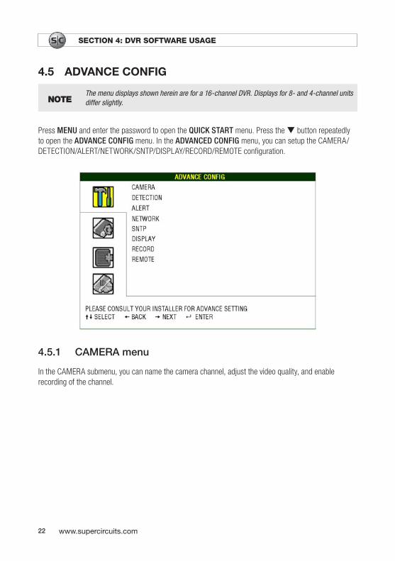
Table 2. Detection area setup
Transparent block indicates an area monitored for detection. Press ENTER to confirm the start area.
Use the t and/or u buttons to choose the width of the detection area.
Use the p and/or q buttons to choose the height of the area.
You can also set up multi-detection area. When any movement is detected, the grids are flashing.
• LS – Level of Sensitivity (on selected models). Use LS to set the sensitivity for comparing two different images. A small value represents a high sensitivity for motion detection.

25H.264 Network DVR User Manual
SECTION 4: DVR SOFTWARE USAGE
• SS – Spatial Sensitivity (on selected models). Use SS to set the sensitivity for detecting the size of one object (the number of the grids) on the screen. A small value represents a higher sensitivity for motion detection.
NOTEThe SS number represents the least number of blocks in which motion is detected for the system to trigger recording. For example, if SS is 05 and motion is detected in 5 or more blocks, a record trigger will occur. The default SS value is 03.
• TS – Time of Sensitivity (on selected models). TS represents how long an object stays in the detection area before triggering a recording. Depending on the model, one of the following options is used:
— Select a value. A small value represents a high sensitivity for motion detection. — Select either HIGH or NORMAL.
• RE – Reference (on selected models). RE sets a reference for detection. With the default value of 10, the DVR will compare 10 continuous images at one time using the parameters LS, SS, and TS.
• ALARM (selected models). Select N.C. (normally closed) or N.O. (normally open) to match the alarm switch design, or select OFF (default).
4.5.3 Alert
Use this menu to enable audible alerts when various system conditions occur. Move to ALERT then press ENTER to open the ALERT menu.

26 www.supercircuits.com
SECTION 4: DVR SOFTWARE USAGE
The submenu items are described below:
• EXT. ALERT – Select ON or OFF to enable or disable a sound when any external alarm is triggered.• INT. BUZZER – Select ON or OFF to enable or disable a sound for all internal conditions: KEY,
VLOSS, MOTION BUZZER, and ALARM. When INT. BUZZER is ON, KEY BUZZER, VLOSS BUZZER, MOTION BUZZER, and ALARM BUZZER can individually be set to ON or OFF.
— KEY BUZZER – Set ON or OFF to enable or disable a sound when pressing the buttons on the front panel.
— VLOSS BUZZER – Set ON/OFF to enable/disable a sound when video loss happened. — MOTION BUZZER – Set ON/OFF to enable/disable a sound when any motion alarm is sensed. — ALARM BUZZER – Set ON/OFF to enable/disable a sound when any internal alarm is sensed. — HDD BUZZER – Set ON/OFF to enable/disable a sound when the HDD remaining capacity
reaches to the value set in HDD NEARLY FULL (GB). — ALARM DURATION (SEC) – Press the p and/or q buttons to set the duration time of alarm
recording in second (5/10/20/40). — HDD NEARLY FULL (GB) – If HDD BUZZER is ON, press the p and/or q buttons to select
the HDD free space threshold at which the alert will occur. Values are 5, 10, 15, or 20 GB.
4.5.4 Network
Use this menu to setup network TCP/IP parameters. Move to NETWORK then press ENTER to open the submenu. The NETWORK screen shows the current network settings. Submenus show parameters relevant to the NETWORK TYPE selected. Options are STATIC, DHCP, or PPOE.

27H.264 Network DVR User Manual
SECTION 4: DVR SOFTWARE USAGE
4.5.4.1 STATIC NETWORK menu
NETWORK TYPE = STATIC opens the STATIC submenu with the following options.
• IP, GATEWAY, and NETMASK – Obtain this information from your ISP (Internet Service Provider) and enter it into these fields.
• PRIMARY DNS/ SECONDARY DNS – Enter the IP address of the DNS suggested by your ISP. • PORT – The valid number ranges from 1 to 9999. The default value is 80, the TCP port typically
used by HTTP. For added flexibility and security, it may be preferable to use a different port number.
See the example below:
4.5.4.2 PPOE NETWORK menu
NETWORK TYPE = PPPOE opens the PPPOE submenu with the following options.
• USER NAME/PASSWORD – Enter the username and password setup by your ISP (Internet Service Provider).
• PRIMARY DNS/SECONDARY DNS – Enter the IP address of the domain name server (DNS) obtained from your ISP.
• PORT – The valid number ranges from 1 to 9999. The default value is 80, the TCP port typically used by HTTP. For added flexibility and security, it may be preferable to use a different port number.
See the example below:

28 www.supercircuits.com
SECTION 4: DVR SOFTWARE USAGE
NOTEThe PPPOE function requires a username and password subscribed from one ISP, and a DDNS account to transform the dynamic IP corresponding to a specific Hostname.
NETWORK TYPE = DHCP opens the DHCP submenu with the following options.
• NETWORK TYPE – Select DHCP.• DNS (PRIMARY DNS/SECONDARY DNS) – Enter the IP address of the domain name server
obtained from your ISP (Internet Service Provider).• PORT – The valid number ranges from 1 to 9999. The default value is 80. Typically, the TCP port
used by HTTP is 80. In some network configurations, it is preferable to set a different port number for added flexibility or security.
See the example below:

29H.264 Network DVR User Manual
SECTION 4: DVR SOFTWARE USAGE
NOTEThe DHCP function must be supported by a router or a cable modem network with DHCP services and a DDNS service to transform the dynamic IP address to a specific Hostname.
4.5.5 SNTP
Use this menu to synchronize your DVR time with networked computer systems. Move to SNTP then press ENTER to open the submenu. The SNTP screen shows the current settings.
NOTE Before using this feature, setup your DVR for internet access.
The submenu parameters include:
• GMT – Select your time zone. • NTP SERVER – Set to the server you prefer to use. • SYNC PERIOD – Select to synchronize the DVR time DAILY, or turn this function off (OFF).
4.5.6 DISPLAY
Use this menu to setup the display properties. Move to DISPLAY then press ENTER to open the submenu. The DISPLAY screen shows the current settings.

30 www.supercircuits.com
SECTION 4: DVR SOFTWARE USAGE
The submenu parameters include:
• DE-INTERLACE – Select ON or OFF to enable or disable the de-interlace function.
NOTEIf you set the recording image size as FRAME, set DE-INTERLACE to ON. If you set the recording image size as CIF, set DE INTERLACE to OFF.
• QUAD DWELL DURATION (SEC) (selected models) – Set the quad dwell duration time to 3, 5, 10, or 15 seconds.
• FULL SCREEN DWELL DURATION (SEC) – Set the full screen dwell duration time to 3, 5, 10, or 15 seconds.
• VGA OUTPUT – Select the VGA output resolution. Options include: 800 x 600 / 1024 x 768 (default) / 1280 x 1024 / 1440 x 900 / 1400 x 1050 / 1680 x 1050 / 1600 x 1200.
NOTEFor the best image quality on your monitor, make sure that the selected DVR VGA output resolution is supported by your monitor, and the monitor is set to that resolution.
If the image is not positioned or scaled properly, make adjustments to the monitor settings. Refer to your monitor user manual.
• DISPLAY COVERT – Select ON or OFF to display or hide the wording COV when covert recording is activated on the CAMERA channel.
• HDD DISPLAY MODE – Select SIZE to show the remaining HDD capacity (in GB) for recording, or TIME to show the remaining recording time.
4.5.7 RECORD
Use this menu to setup the record features of the DVR. Move to RECORD, then press ENTER to open the submenu. The RECORD screen shows the current settings.

31H.264 Network DVR User Manual
SECTION 4: DVR SOFTWARE USAGE
Submenu parameters include:
• MANUAL RECORD ENABLE – Set the manual recording function ON or OFF. • EVENT RECORD ENABLE – Set the event recording function ON or OFF. • TIMER RECORD ENABLE – Set the timer recording function ON or OFF. • EVENT RECORD IPS – Select the images per second (IPS) for EVENT RECORD (recording that is
triggered by an alarm or motion detection).
NOTE Different DVR models can record at different rates. See “Specifications”.
• TIMER RECORD IPS – Select the IPS for TIMER RECORD (scheduled recording).• OVERWRITE – Select ON to overwrite previous recorded data in your HDD when the HDD is full.
When this function is ON and the HDD is full, the DVR will clear the oldest 8 GB data without notice to continue recording.
• EVENT RECORD ALL CHANNELS – Select to record all channels (ON) or record the channel with an event only (OFF).
• KEEP DATA LIMITS (DAYS) – Assign the maximum number of days to keep recorded data (01 to 31). Data older than the specified number of days will be removed. Select OFF to disable this feature.
4.5.8 REMOTE
Use this menu to setup remote devices (cameras, etc.). Move to REMOTE, then press ENTER to open the submenu. The REMOTE screen shows the current settings.

32 www.supercircuits.com
SECTION 4: DVR SOFTWARE USAGE
Submenu parameters include:
• TITLE – Show the title of each channel set in the CAMERA menu.• DEVICE – Select the type of device (CAMERA/PTZ) on the channel. • ID – Set the ID number (0 ~ 255) for a PTZ camera. After connecting to a PTZ camera, the default
ID of the PTZ camera will be shown on the screen. • PROTOCOL – Select NORMAL (Supercircuits protocol), P-D (PELCO-D), or P-P (PELCO-P) protocol.• RATE – Set the baud rate of each channel (2400/4800/9600/19200/57600/115200) to match
the setting in the camera.
4.5.9 PTZcamerasetup
a. In the REMOTE submenu, highlight the channel where the speed dome camera is attached.
b. In the DEVICE column, select PTZ (for the speed dome camera).
c. Move to the ID column and set the ID number of the camera.
d. In the PROTOCOL column select P-D (for Pelco-D), P-P (for Pelco-P), or NORMAL for all other protocols.
e. Set the baud rate to the value configured in the camera.
f. Press MENU to confirm your entries and exit the menu.

33H.264 Network DVR User Manual
SECTION 4: DVR SOFTWARE USAGE
4.6 SYSTEM INFO
Use this menu to setup several system level parameters including password and video format, and to initiate a firmware upgrade. Move to SYSTEM INFO, then press ENTER to open this submenu. The SYSTEM INFO screen shows the current settings.
Submenu parameters include:
• SERIAL TYPE – Serial communications methodology of the DVR (RS485).• BAUD RATE – Set the baud rate of the DVR. Options are 2400, 9600, 19200, 38400, 57600, or
115200.• HOST ID – Set the ID of the DVR (0 ~ 254).• PASSWORD – Set the password for accessing the DVR system. Passwords can have up to 4 digits.• RESET DEFAULT – Press ENTER to reset all parameters to the default values. When resetting
parameters, select YES to confirm or NO to cancel.• CLEAR HDD – Select the HDD. Press ENTER, then select YES to confirm to clear HDD or NO to
cancel.• UPGRADE – For upgrading firmware/OSD. See “Firmware / OSD upgrade” for more information. • R.E.T.R. (MIN) – Remote Event Trigger Recording (selected models). Select the timeout after which
the R.E.T.R. function will be activated. Options include 03, 05, 10, or 30 seconds. R.E.T.R. On – Press the R.E.T.R. key on the IR remote control to enable the timeout function. Enter the password, and the R.E.T.R. delay icon (green background) appears. When the RETR function is activated, the R.E.T.R. On icon (red background) appears. R.E.T.R. Off – Press any key (except POWER) and enter the password to turn off R.E.T.R.

34 www.supercircuits.com
SECTION 4: DVR SOFTWARE USAGE
• AUTO KEYLOCK – Set the time-out in second after which the key lock function is activated. Options are Never, 10 seconds, 30 seconds, or 60 seconds.
• LANGUAGE – Select the language of the OSD.• VIDEO FORMAT – NTSC only. • VERSION – The firmware version installed.
4.6.1 Settingthepassword
1. In the System Info submenu, press the u button once, then press the p or q buttons until PASSWORD is highlighted.
2. Press the u button once, then press ENTER.
3. Enter the OLD PASSWORD as described above.
4. Enter your NEW PASSWORD.
5. Press MENU to exit the configuration displays.
4.7 EVENT INFO
Use this menu to search for event information. Move to the EVENT INFO icon, then press ENTER to open the TIME SEARCH (QUICK SEARCH) submenu. The EVENT INFO screen shows the current settings. Selecting any of the options on this screen opens a submenu.

35H.264 Network DVR User Manual
SECTION 4: DVR SOFTWARE USAGE
4.7.1 QuickSearch
Use this menu to search for events by time and play the file you find. Move to QUICK SEARCH, then press ENTER to open the submenu.
Submenu parameters include:
• DATE – Select the time period (YEAR / MONTH / DAY HOUR : MIN : SEC) you want to search for.• SEARCH HDD – If there is more than one HDD installed, select the HDD you want to search. Select
the HDD using the p and/or q buttons .• START – Move to START then press ENTER to initiate the search and playback the recorded files.
4.7.2 EventSearch
Use this menu to search for events by event type. Move to EVENT SEARCH, then press ENTER to open the submenu.

36 www.supercircuits.com
SECTION 4: DVR SOFTWARE USAGE
Submenu parameters include:
• DATE – Set the date and time of the event you want to search for. • CHANNEL – Press the p and/or q buttons to select the channel.• EVENT – Select the event type: MOTION or ALARM.• SEARCH – Change to the HDD you want to search in if the DVR has more than one HDD. Use the
p and/or q buttons to select the HDD. • START – Move to START then press ENTER to search and playback the recorded files.
4.7.3 HDDINFO
Use this menu to display the configuration of the HDDs installed in the DVR.
Use this menu to view the event log. Page forward (NEXT) and back (PREV) through the log, or clear (CLEAN) the log by selecting the on-screen functions.
4.7.4 EVENTLOG
Use this menu to view the event log. Page forward (NEXT) and back (PREV) through the log, or clear (CLEAN) the log by selecting the on-screen functions.

37H.264 Network DVR User Manual
SECTION 4: DVR SOFTWARE USAGE
4.8 BACKUP
Press MENU and go to the BACKUP icon to open the BACKUP submenu. Clicking USB BACKUP or DISK BACKUP opens a submenu.

38 www.supercircuits.com
SECTION 4: DVR SOFTWARE USAGE
4.8.1 USBBACKUP
Video/audio files can be copied to a USB device, such as a USB flash memory drive, for archiving. Move to USB BACKUP, then press ENTER to open the USB BACKUP submenu.
Before making USB backup, verify that:
1. The USB flash drive is supported by your DVR (see Compatible USB Flash Drive). If it is not compatible, the message USB ERROR will appear.
2. The USB flash drive must be formatted as FAT32. If not, use a computer to format it for FAT32.
3. Erase existing files from the USB flash drive before using it to backup DVR data.
NOTE When USB backup is in progress, do not use the DVR for other operations.
NOTEYou can backup up to 2 GB of video data at one time. To backup more data, set the time and channel(s) you want, and start the USB backup again.
Submenu parameters include:
• START TIME – Select the start time of the backup data.• END TIME – Select the end time of the backup data.• AVAILABLE SIZE – Display the available capacity of the inserted USB flash drive.

39H.264 Network DVR User Manual
SECTION 4: DVR SOFTWARE USAGE
• CHANNEL – Select channels by pressing ENTER to toggle the icon in front of the channel number.- The R (checked box) icon indicates that this channel is selected for backup.- The * icon indicates that this channel is not selected for backup.
• HDD NUM – Press ENTER to select the HDD containing the data you need.• START – Press ENTER to start copying data to the USB flash drive.
4.8.2 DISKBACKUP(selectedmodels)
Video/audio files can be copied to the CD or DVD drive installed in the DVR. In the BACKUP menu, move to DISK BACKUP, then press ENTER to open the submenu.
Submenu parameters are similar to the USB BACKUP parameters. Included are:
• START TIME – Select the start time of the backup data.• END TIME – Select the end time of the backup data.• AVAILABLE SIZE – Display the available capacity in the CD/DVD disk media. • CHANNEL – Select channels by pressing ENTER to change the symbol in front of the channel
number. - The R (checked box) icon indicates that this channel is selected for backup.- The * icon indicates that this channel is not selected for backup.
• HDD NUM – Press ENTER to select the HDD containing the data you need.• START – Press ENTER to start copying data to the CD/DVD.
To perform a disk backup, follow the general procedure:
1. Press EJECT to open the disk tray. Insert a CD or DVD into the DVD writer then press EJECT again to close the disk tray.

40 www.supercircuits.com
SECTION 4: DVR SOFTWARE USAGE
2. Press MENU, go to the BACKUP menu, and select DISK BACKUP.
3. Set the start time, end time, and select the channels and HDD to backup.
4. Highlight START then press ENTER to begin the backup process. A completion indicator will appear.
NOTEThe system can backup up to 41 files to a CD or DVD. During the backup process, a file player is copied to the disk and the message BACKUP PLAYER is shown on the screen.
5. When the backup process is finished, BACKUP SUCCESS appears. Press EJECT to open the disk tray and remove the disk.
NOTEWhen the backup disk is used in a PC, install the PLAYER.exe file copied to the disk, if necessary, to view the video files.

41H.264 Network DVR User Manual
SECTION 5: BASIC OPERATION
SECTION 5 Basic Operation
5.1 Live page
On the Live page, you can see a 1- , 4-, 9-, or 16-cut screen with status icons. See the following picture.
Motion
Channel name
Available HDD Capacity
Recording
System Time Status Bar
Table 3. Live page icon definitions
Icon Function Icon Function Icon Function Icon Function
Key lock
Key unlock
Digital zoom mode
Digital zoom unselected
The 1st live audio channel
The 2nd live audio channel
The 3rd live audio channel
The 4th live audio channel
The 1st play-back audio channel
The 2nd play-back audio channel
The 3rd playback audio channel
The 4th playback au-dio channel
Audio channel unselected
Timer recording
Motion
Recording
Alarm (selected models)
HDD over-write
R.E.T.R. ON (selected models)
R.E.T.R. De-lay (selected models)

42 www.supercircuits.com
SECTION 5: BASIC OPERATION
5.1.1 Recordingicons
1. Continuous recording – By default, the record icon appears when the DVR is powered on and an HDD is installed.
2. Event recording – When motion detection is sensed or an alarm is activated, the motion icon or alarm icon appears.
3. Timer recording icon – When the record timer is activated, the Timer icon appears.
NOTEA new log is added in the system log when HDD data is overwritten or when recording starts after the DVR reboots.
4. HDD Overwritten Icon – The HDD overwritten function can be set to ON/OFF. When this function is enabled (ON), the icon appears.
NOTEWhen the HDD overwrite function is activated, this device will overwrite the oldest 8 GB of data to free storage space for new data. No notice is provided when data is overwritten.
5.2 Playback
Press PLAY on the DVR control panel to play the last recorded video.
NOTEThere must be at least 8192 images of recorded data for playback to work properly. If not, the device will stop playback. For example, if the IPS is set to 30, the recording time should be at least 274 seconds (8192 images at 30 IPS) for the playback to work properly.
NOTE Playback at the local site may not be smooth if remote surveillance is occurring simultaneously.
• Fast Forward/Fast Rewind – You can increase the speed for fast forward and rewind. In Playback mode:
— Press FF once to play at 4X speed forward; press twice to play at 8X speed, etc. The maximum forward speed is 32X.
— Press REW once to play in reverse at 4X speed; press twice to play in reverse at 8X speed, etc. The maximum reverse speed is 32X.
• Pause/Image Jog – Press PAUSE to pause playback. In the Pause mode: — Press FF once to move one frame forward.

43H.264 Network DVR User Manual
SECTION 5: DVR SOFTWARE USAGE
— Press REW once to move one frame backward.• Stop – Pressing STOP during playback mode returns to live monitoring mode.• Slow Playback – Press SLOW to move forward at 1/4X speed playback; press twice to move
forward at 1/8X speed playback.• Audio Playback (SLOW + ZOOM) – Press SLOW and ZOOM simultaneously to select the live
sound or playback sound on the audio channel.
5.3 Key lock and unlock
• Key Lock On – Set the time-out after which the key lock function is activated (NEVER / 30 SEC / 60 SEC / 120 SEC). Refer to SYSTEM INFO. or press F2 on the IR remote control to lock the keys immediately.
• Key Lock Off – Enter the DVR password to exit Key Lock mode.
5.4 Firmware upgrade
DVR firmware rarely needs to be upgraded. Should it be necessary, contact Supercircuits Support at 1.800.335.9777 to acquire the latest firmware. Firmware can be upgraded using a USB flash memory device, or through the Video Viewer application.
Upgrading firmware using a USB flash memory device:
1. Format the USB flash memory device as FAT32 format.
2. Obtain the upgrade file(s) from Supercircuits Support. Copy the upgrade file(s) to your USB flash memory device (do not change the file name).
3. Plug the USB flash memory device into the USB port on the front of the DVR. Wait until the DVR detects your USB flash memory device.
4. Press MENU, and go to the SYSTEM INFO menu. Select UPGRADE > START, then press ENTER.
5. At the confirmation query, select YES, then press ENTER to confirm the upgrade.
6. Allow the upgrade process to complete before continuing.
Upgrading firmware using the Video Viewer application:
1. Save the upgrade files on your PC (do not change the file name).
2. Start the Video Viewer application.
44 www.supercircuits.com
SECTION 5: DVR SOFTWARE USAGE
3. In the “Address Book” panel, select the IP address of your DVR (add the IP address of your DVR to the address book if necessary).
4. Click the icon to show the Update Server panel.
5. In Update Server, click the Firmware or Language tab as needed.
6. Click Add and select the firmware or OSD files to upgrade.
7. Click Update Firmware or Update Language to start the upgrade.
8. Allow the upgrade to complete before continuing.
5.5 Search
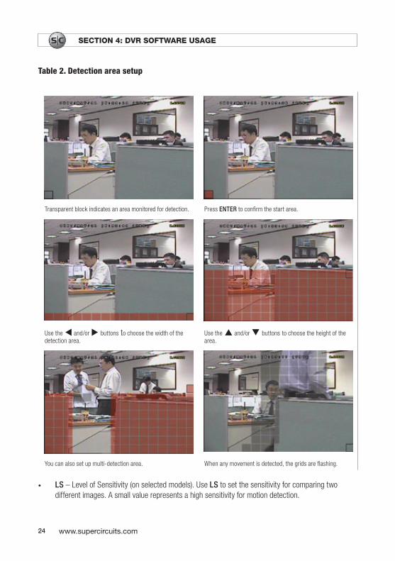
Search by List
Press LIST on the DVR control panel to open the LIST menu. Move to the item you want to view or search, then press ENTER.
Search by Time
Press MENU and open the EVENT INFO menu.
a. Select QUICK SEARCH, then press ENTER to open the TIME SEARCH screen.
b. Search for specific events by time (Year / Month / Day Hour : Min) or select HDD.

45H.264 Network DVR User Manual
SECTION 6: LOCAL AND REMOTE OPERATION
SECTION 6 Local and Remote OperationYour DVR can be accessed from a personal computer (PC) for remote viewing of cameras and retrieval of stored video streams. DVRs can be setup for remote viewing across a private Local Area Network (LAN) and across a Wide Area Network (WAN), such as the internet, using the Video Viewer software provided on the CD with your DVR, Microsoft® Internet Explorer® browser, and Apple® QuickTime® player, and the Apple iPhone® SC Mobile app.
6.1 Networking your DVR
Before you can access your DVR across a Local Area Network (LAN), it must be configured for the network it is attached to. Similarly, before the DVR can be accessed from the Internet (WAN), the network it is attached to must be configured to allow access to the DVR from the internet. For guidelines on setting up your DVR for LAN and WAN access, refer to Supercircuits “DVR Networking Guide” provided on the CD with your DVR, or from the DVR’s product information page at Supercircuits.com.
6.2 Video Viewer software
Video Viewer is a central management system (CMS) software program for viewing and controlling your DVR from a PC. It includes the following features:
• Surveillance and management of up to 16 sites simultaneously• Multiplex operations (live view, record, playback, backup and network) with intelligent motion
detection functions• Google connection for E-map application• Pre- and post-event recording • GUI record log and event search • PTZ camera control
Video Viewer can be installed on the following operating systems:
• Microsoft Windows® 2000 • Microsoft Windows XP • Microsoft Windows Vista
Before using Video Viewer, make sure that you have configured the DVR and network for LAN and/or WAN access.

46 www.supercircuits.com
SECTION 6: LOCAL AND REMOTE OPERATION
6.2.1 InstallVideoViewersoftware
To install the Video Viewer software:
1. Place the CD supplied with your DVR into your CD-ROM or DVD-ROM drive of your PC.
2. Open the CD in a file browser, such as Windows explorer.
3. Find the file named VideoViewer.exe or setup.exe. Double-click on this file name to open (run) it.
4. Follow the on-screen instructions to complete the installation. When the installation finishes, a Video Viewer shortcut icon, , will appear on your PC desktop.
6.2.2 NetworkconnectionviaLAN/WAN
A PC on the same LAN as the DVR, or on the internet, can be used to configure and manage the DVR. To access your DVR with Video Viewer:
1. Double-click the Video Viewer icon on your PC desktop to open the Video Viewer control panel. By default, the “Address Book” window also opens.
2. In the Address Book window, click the icon (Add) in the Address Book window. Create an entry for your DVR: entry the IP address, port, user name, password, and select other parameters as need. Click Apply.
3. In the Address Book window, double-click the entry you created. A simplified control panel view will appear.

47H.264 Network DVR User Manual
SECTION 6: LOCAL AND REMOTE OPERATION
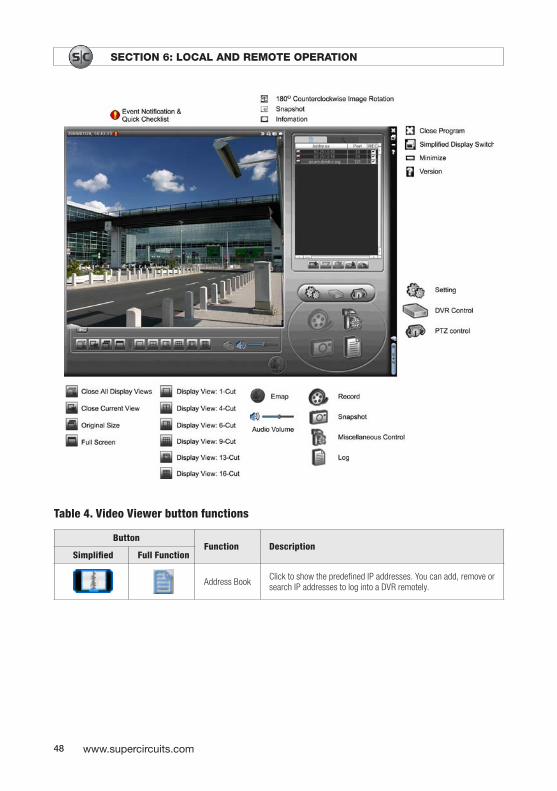
6.2.3 VideoViewerdisplays
The Video Viewer simplified control panel is shown below. Clicking the Full Function Display Switch maintains the connection to the DVR and opens the Full Function Display.
The Full Function display mode provides an enlarged view of the DVR screen and additional controls.
48 www.supercircuits.com
SECTION 6: LOCAL AND REMOTE OPERATION
Table 4. Video Viewer button functions
ButtonFunction Description
Simplified Full Function
Address Book
Click to show the predefined IP addresses. You can add, remove or search IP addresses to log into a DVR remotely.

49H.264 Network DVR User Manual
SECTION 6: LOCAL AND REMOTE OPERATION
ButtonFunction Description
Simplified Full Function
Miscellaneous Control
Remote Config
Click to go to the detailed DVR settings.
Record Setting
Click to go to the detailed record settings.
Custom Setting
Click to choose a screen language. A language change takes effect when the program is restarted.
Log
Click to view all event and recording logs. Search log(s) by date, or playback the recording.
Record Record Stop
Click to start/stop manual recording.
SnapshotClick to take a snapshot of the current view. Snapshots are saved in the path specified in Record Setting.
Information Click to show network connection details.
DVR Control Click to go to the DVR control panel to operate the DVR remotely.
6.2.4 Operations
6.2.4.1 Record
To record events or alarms at your PC, click or and -> to go to the “Record Setting” page.

50 www.supercircuits.com
SECTION 6: LOCAL AND REMOTE OPERATION
In the “Record Setting” window, you can set the following items:
• Record type• Hard disk overwrite• Pre- and post-alarm record time (in seconds)• Record time range• Recorded data storage location (Record Path)
If Manual is checked, click or on the main control panel to start the manual recording immediately. The recordings are saved in the location specified in Record Path. The red text REC indicator will be shown at the top left corner of the image display view.
If Motion and/or Alarm are checked, the recording function is enabled by Video Viewer when an event is triggered at the DVR. Recordings are saved at the location specified in the DVR configuration.
6.2.4.2 Playback
To play a recording, click or , and select the Record or Backup tab. By default, a list of all recordings is shown. You can also sort event logs to speed search time.

51H.264 Network DVR User Manual
SECTION 6: LOCAL AND REMOTE OPERATION
To play a recording, select a log entry from the list and click Play, or double-click the entry.
6.2.4.3 Network Backup
Click -> , or click to open the Backup window. Select the time range or event for which you want to make a video backup. File(s) you backup are from the currently selected IP address and HDD.

52 www.supercircuits.com
SECTION 6: LOCAL AND REMOTE OPERATION
Table 5. Video Viewer backup window parameters
Function Description
HDD Number/channel
Specify the HDD number and channel associated with the video data you want.
Download by Time In the “Start Time” and “End Time” columns specify the time range within which the video data was recorded.
Download by Event Select an incident from the event list. The list shows all logs in the DVR from latest to earliest. - To find the events you want to see, check or uncheck the event type System/Manual/Alarm/Motion, then select the log you want. - Click “Prev. Page” or “Next Page” to page through the log list. - Click “Reload” to refresh the event list.
File Path Assign the location where backup files are saved.
Simultaneous Playback
To view backup images while a download is in progress, select the checkbox “Simultaneous Playback”. To backup images without previewing, deselect the checkbox “Simultaneous Playback”. You will only see a message box indicating the total time needed, the current status, and the saving location.
Download/Cancel Click “Download” to start or “Cancel” to discard the video backup.
6.2.5 E-Mapfeatures
Video Viewer provides network device control and management (E-Map) for up to 16 devices simultaneously. E-Map is available only when the control panel is set to full-function view.

53H.264 Network DVR User Manual
SECTION 6: LOCAL AND REMOTE OPERATION
NOTE Before using this feature, connect Video Viewer to the devices you want to monitor.
6.2.5.1 Adding an E-Map group
1. If Video Viewer is in simplified view mode, click to switch the control panel to the full-functionview. Click to open the E-Map page.
2. Right-click to open the shortcut menu in the top-left panel.
3. Select the E-Map group you want to add. There are three E-Map group types you can add: Google E MAP, single E MAP, and building E MAP.

54 www.supercircuits.com
SECTION 6: LOCAL AND REMOTE OPERATION

55H.264 Network DVR User Manual
SECTION 6: LOCAL AND REMOTE OPERATION
4. When the E Map group is created, a tree appears on the top-left panel showing the devices you’ve added to this group.
Table 6. E-Map device tree icons
Icon Description
The connected device is camera. When selected, it is red.
The connected device is DVR. When selected, it is red.
This icon appears for any motion or alarm event. Double-click the device icon on the E-Map to show the live view.
6.2.5.2 Edit/remove an existing E-Map group
For Google E-Map group
To edit or remove an existing Google E-Map group, right-click on the group name to show the shortcut menu list. Select Edit E MAP or Remove E MAP as desired.
You can also add a single E Map group (Add Single E-MAP) or building E-Map group (Add Building E-MAP) into the existing Google E-Map group.

56 www.supercircuits.com
SECTION 6: LOCAL AND REMOTE OPERATION
For a single E-Map group
To edit or remove an existing single E-Map group, right-click on the group name to show the shortcut menu list. Select Edit E MAP or Remove E-MAP as required.
For a building E-Map group
To edit or remove an existing building E Map group, right-click on the group name to show the shortcut menu list. Select Edit Building E MAP or Remove E MAP as required.

57H.264 Network DVR User Manual
SECTION 6: LOCAL AND REMOTE OPERATION
To edit or remove a certain level of the building E Map group, right click on the level name. Select Edit E MAP or Remove E MAP as required.

58 www.supercircuits.com
SECTION 6: LOCAL AND REMOTE OPERATION
6.3 Web browser
You can view the images or operate your DVR with Microsoft Internet Explorer (IE), Mozilla Firefox, or Safari web browsers. The following operating systems are supported:
• Microsoft Windows 2000• Microsoft Windows XP• Microsoft Windows Vista• Mac OS® X
1. Enter the IP address used by your DVR into the URL box on your browser then press Enter.
If you are accessing your DVR with IE across a local LAN, enter the local IP address of the DVR into the URL field. For example, enter 192.168.1.201.
If you are accessing your DVR with IE across a WAN (Internet), and the port number assigned to the DVR is NOT 80, you must include the port number with the IP address. The format is http://ipaddress:portnum. For example, if the IP address is 60.121.46.236 and port number is 888, enter ”http://60.121.46.236:888” into the URL address box, then press Enter.
2. You will be prompted to enter the user name and password to access the DVR. Enter the user name and password for the DVR you are logging into, then click OK.
NOTEThe buttons and functions described below are for a 4-channel DVR. The description for 8- and 16-channel systems is similar.
You will see a screen similar to the following when the login information is correct.

59H.264 Network DVR User Manual
SECTION 6: LOCAL AND REMOTE OPERATION
Table 7. Web browser button function
NO. Function Description
1 Home Click to go to the main page of the DVR.
2 Config. Click to go to the detailed DVR setting.
3 PTZ Click to enter PTZ mode.
4 Channel Selection Click one of the numbers to switch to the channel you want to see in full screen mode.
5 Selection Click or to go to the previous/next channel, or change a setting.
6 Display Mode
Click to show 4-cut display.
Click to display channels one by one starting with CH1. When the last channel is displayed, it will return to CH1.To exit from this mode, press any other channel display button.
7Menu and Arrow Keys
Click to open the menu/exit the menu mode.
/ : Move up/down to select the previous/next menu or sub-menu function, or change the setting.
/ : Move left/right to the previous/next sub-menu items.
8 Event Click to open the playback search settings screen.

60 www.supercircuits.com
SECTION 6: LOCAL AND REMOTE OPERATION
NO. Function Description
9 Snapshot Click to take a snapshot of the current view and open another browser window to display the captured image.
10 Key Lock Click to enable the DVR key lock function. To unlock the DVR, enter your password, then click Enter.
11 Enter Click to confirm the setting, or enter your selection.
12 Digital Zoom Click to zoom in/out the selected channel image.
13 Search Click to open the DVR full search menu. Here you can check all the logs and select one to payback.
14Playback control buttons
(Stop) / (Play) / (Rewind) / (Forward) / (Pause) / (Slow Playback) Rewind/Forward – Click once to move at 4X fast rewind/forward, twice to move at 8X, three times to move at 16X, and four times to move at 32X. Slow Playback – Click once to move at 4X slow playback and twice to move at 8X slow playback.
15 Web TransmissionH.264/M-JPEG/QuickTime (depending on the model you have). When “QuickTime” is selected, you are promoted to enter the user name and password to access the server of the DVR.
16 Change Quality BEST/HIGH/NORMAL/BASIC – Click to change the image quality.
17 Change Resolution 4 CIF/CIF. Click to change the image resolution (4CIF: 704x480/CIF: 352x240)
18Remote Indepen-dent Operation Off/On
Click it to disable/enable the network independent function.
19Audio channel Selection
Select the audio channel in live mode or playback mode.
Indicates that no camera supporting audio recording is connected to the DVR.
6.4 Apple QuickTime player
With Apple QuickTime player you can remotely log into the DVR and view the on-screen image. The DVR image quality must be set to BEST to see the DVR screen. No DVR control features are available with Apple QuickTime.
1. If QuickTime is not installed on your PC, go to: http://www.apple.com/. Download and install the free version.
2. Open QuickTime player. In the player window, select File > Open URL…

61H.264 Network DVR User Manual
SECTION 6: LOCAL AND REMOTE OPERATION
3. In the popup window, enter the Internet URL in the format rtsp://ipaddress:portnum/live/h264 (For example, rtsp://60.251.8.57:88/live/h264). ipaddress:portnum is the IP address and port number of your DVR.
4. Click OK to continue.
5. In the Internet Authentication window, enter the Userid and Password for accessing your DVR, then click OK to continue.

62 www.supercircuits.com
SECTION 6: LOCAL AND REMOTE OPERATION
NOTEIf you’re not prompted to enter a Userid and Password, and the error message 10060 appears, go to Edit > Preferences > QuickTime Preferences, and select “Streaming Transport” from the drop-down list. Select “Use HTTP”, and keep the port ID as 80.
6. When the login is successful, you will see the live view from the DVR.
6.5 SC Mobile App for iPhone
SC Mobile Phone Surveillance provides access to your DVR video and audio through an Apple® iPhone®. The application, SC Mobile, can be downloaded for free from the Apple App Store.
SC Mobile includes the following features:
• Address Book (1 entry)• Auto playback after an event alarm is triggered • PTZ Preset Point Setting • Real Time Video Streaming • Real Time Audio Streaming • Video Quality Control • Auto Re-login • PTZ Hot Point Control
NOTEThe network on which your DVR is installed must be configured to allow access to the DVR through the Internet. Refer to your DVR reference manual and the Supercircuits “DVR Networking Guide” for specific guidelines for setting up your DVR on a network with Internet access.
NOTETo stream video data to your iPhone with the SC Mobile app, you must first connect your iPhone to a Wi-Fi network. For more information about Wi-Fi connectivity and your iPhone, refer to your user documentation and your service provider.
6.5.1 Installation
To install SC Mobile:
1. On your iPhone, open the App Store.

63H.264 Network DVR User Manual
SECTION 6: LOCAL AND REMOTE OPERATION
App Store Icon
2. Search for SC Mobile.
3. After SC Mobile is found, select it.
4. Install the application.
5. Find the SC Mobile application on your phone application display.

64 www.supercircuits.com
SECTION 6: LOCAL AND REMOTE OPERATION
6.5.2 Setup
You can setup the SC Mobile application with at most one address book entry. When the application is first opened, the Addressbook will contain a default entry named “Demo Site”, with which you can become familiar with the application. The Demo Site DVRs are hosted in Taiwan.
Before adding an Addressbook entry for your DVR, you must delete the Demo Site entry. You can also edit the Demo Site settings to access your DVR. In the following procedure, the Demo Site entry is deleted and a new entry is created.
1. Open the SC Mobile application.
2. Click the Demo Site entry in the address book to highlight it, then click the Delete button in the lower right corner of the screen. The Demo Site entry will disappear.
Add Button
Edit Button
Delete Button

65H.264 Network DVR User Manual
SECTION 6: LOCAL AND REMOTE OPERATION
3. Click the + (Add) button in the lower left corner of the screen. A New Item entry will appear.
4. Tap the Addressbook entry you added to highlight it, then tap the submenu icon, , for additional settings.
Submenu Icon
5. In the Setting screen, tap the item you want to specify, then key in the appropriate information. Press Done to complete each entry. Specify the Title, IP Address, Port (if other than 80), Username and Password for your DVR. If the DVR is setup with a dynamic IP address and you use a web-based service, such as DynDNS, to connect to your DVR, enter your DVR URL into the IP address field.
6. If your DVR system has audio capability, set the Audio option to ON. For channel selection, tap the submenu icon, , for additional settings.
7. Tap the Get Type button to see if you can connect to your DVR. If a connection is successful, the DVR type will appear in the field to the right. Otherwise, change the network settings as needed, then tap Get Type again to connect to the DVR.
8. If the connection was successful, press the Save button in the upper right corner to return to Addressbook.

66 www.supercircuits.com
SECTION 6: LOCAL AND REMOTE OPERATION
NOTEThe SC Mobile Audio feature is not functional with DMR40DVD-2, DMR41DVD-2 and DMR42DVD-2 DVRs.
9. On the Addressbook screen, tap the Settings button in the upper-right corner to configure the advanced options. These options include Auto login – Slide to ON to automatically log into the device in the Addressbook. Gesture Command – ON by default, slide to OFF to disable the direct-touch operations. When OFF, operate the device by touching the function buttons on the screen. PTZ Turbo – Speed up PTZ control (for Pan/Tilt/Zoom cameras only). For example, when set to ”2”, the program interprets one touch as two touches. Auto Lock – When ON, disables the iPhone keylock (hibernate when not in use) when there is no connection and the iPhone keylock is ON.
10. After making changes to the Settings screen options, press Save.
6.5.3 UsingtheSCMobileapp
1. Connect your iPhone to a Wi-Fi network. When the iPhone is connected to a Wi-Fi network, the Wi-Fi icon, , appears at the top of the screen.
2. Open SC Mobile by tapping the icon on the app screen. Tap the icon in the upper left corner to open the SC Mobile information screen. Tap Done to return to Addressbook.

67H.264 Network DVR User Manual
SECTION 6: LOCAL AND REMOTE OPERATION
6.5.4 LogintoyourDVR
Tap the entry in Adressbook to login to your DVR. SC Mobile will connect to your DVR and open a channel display. See the following screen captures. If you turn the iPhone sideways, and enlarged view of the channel display appears.
6.5.5 Usingthedisplayfeatures
• After logging into a DVR, press the button at the top of the screen to overlay the screen with the Addressbook settings for the current connection.

68 www.supercircuits.com
SECTION 6: LOCAL AND REMOTE OPERATION
IP Address – Shows the IP address or domain name of the connected device.
Resolution – Shows the image resolution (in pixels).
Quality – Shows the current image quality setting.
Audio – Shows whether the audio function is set to ON or OFF.
Frame Rate – Shows how many images are received by the DVR in one second.
Server Time – Shows the current date and time of the server.
Online User – Shows how many users are logged into this device.
• Press the button at the top of the screen to open the channel display screen.
To listen to (monitor) an audio channel, tap the audio icons at the bottom of the screen. In the example above, channel 1 is being monitored.
• On the channel display screen, tap a grid icon to select a 4, 9, or 16 channel display, then tap the channels block you want to display.

69H.264 Network DVR User Manual
SECTION 6: LOCAL AND REMOTE OPERATION
• To view a single channel, press the button then press the channel number you want to see.
6.5.6 PTZcameracontrol
SC Mobile provides pan/tilt/zoom control of PTZ cameras. When a channel with PTZ features is displayed, icons located at the bottom of the screen can be used to control many pan/tilt/zoom functions. Touch and motion gestures on the camera image can be used to issue several commands.
Camera control buttons
When viewing images from the a PTZ camera, control buttons appear at the bottom of the screen.

70 www.supercircuits.com
SECTION 6: LOCAL AND REMOTE OPERATIONON
Camera Control Buttons
Table 8. PTZ Camera control buttons
Button Description
Slight zoom in – This zoom in mode allows greater zoom control than the touch and motion gestures on the camera image (see Step zoom in/out below).
Slight zoom out – This zoom out mode allows greater zoom control than the touch and motion gestures on the camera image (see Step zoom in/out below).
Focus near – for adjusting the focus setting.
Focus far – for adjusting the focus setting.
Tilt – Tilts camera back 180°.

71H.264 Network DVR User Manual
SECTION 6: LOCAL AND REMOTE OPERATION
Button Description
Preset – Depending on the camera’s capability, this feature allows you to preset a camera direction and zoom setup, and move the camera to that setup with a simple command. Up to six camera presets can be established.
Setting a preset: Set the camera direction and zoom to a configuration you want to preset. Tap the Preset button, then press and hold for 3 seconds one of the six buttons that appear at the bottom of the screen. When the pop-up menu appears, tap OK.
Tap
Press and Hold
Tap
Move to preset: Tap the Preset button, then tap the number buttons associated with the preset you want to move the camera to.
Tap
Tap
6.5.7 Swipeleft,right,up,ordown
To move the camera left, right, up or down, swipe your finger across the screen in the opposite direction.

72 www.supercircuits.com
SECTION 6: LOCAL AND REMOTE OPERATION
For example, to move the camera to the right, swipe the picture off to the left.
6.5.8 Logout
Return to addressbook, or press the iPhone Home button to close app.

73H.264 Network DVR User Manual
SECTION 7: SPECIFICATIONS
SECTION 7 SpecificationsSpecifications shown in the following tables are subject to change without notice.
Table 9. Specifications
Model DMR42DVD DMR41DVD DMR40DVD
Video system NTSC
Video compression format H.264
Video input (Composite video signal 1 Vp-p 75Ω BNC)
16 channels 8 channels 4 channels
Video loop output (Composite video signal 1 Vp-p 75Ω BNC)
16 channels 8 channels 4 channels
Video output (BNC)
Main monitor output For static display
Call monitor output For sequence display
Video output (VGA) (up to 1600 x 1200) Yes
Audio input 4 channels (mono) 4 channels (mono)
Audio output 2 channels (mono) 1 channel (mono)
Multiplex operation Supports live display, record, playback, backup, and network simultaneously
Maximum record rate (frame) 120 IPS @ 704×480 60 IPS @ 704×480 30 IPS @ 704×480
Maximum recording rate (field) 240 IPS @ 720×240 120 IPS @ 704×240 60 IPS @ 704×240
Maximum recording rate (CIF) 480 IPS @ 360×240 240 IPS @ 360×240 120 IPS @ 352×240
Recording mode Manual/Timer/Motion/Alarm/Remote
Recording quality options Super Best, Best, High and Normal
Pre-alarm recording Yes (up to 30 seconds)
HDD Type SATA
HDD storage. HDDs are optional. Supports up to 1TB per HDD
Up to two SATA HDDs Up to one SATA HDD
HDD Quick Cleaning Delete HDD data efficiently (1TB within 2 seconds)
Quick Search Time/Motion/Alarm
USB Flash Drive Backup Yes
DVD Writer Backup Yes
Network Transfer Format H.264
Ethernet 10/100 Base-T.
Network Protocols TCP/IP, PPPOE, DHCP

74 www.supercircuits.com
SECTION 7: SPECIFICATIONS
Model DMR42DVD DMR41DVD DMR40DVD
Network Surveillance InterfaceLicensed software Video Viewer/Microsoft Internet Explorer and Firefox web browsers/ Apple QuickTime/Apple Safari/Apple iPhone SC Mobile App
Remote Independent Operation Yes
Network Alarm Notification E-mail and FTP server
CMS (Central Management System) Yes (up to 16 IP addresses)
R.E.T.R. (Remote Event Trigger Recording) NO Yes
Operating System for Network FunctionWindows Vista/XP/2000; Apple Mac OS X (browser or QuickTime only, no software)
IR Remote Control Yes
Multilingual OSD Yes
Motion detection area 16 × 12 grids per channel
Motion detection sensitivity 4 adjustable parameters for accurate detection
PTZ Control Pelco-D/Pelco-P
External alarm 16 inputs, 1 output 8 inputs, 1 output 4 inputs, 1 output
Picture zoom 2X digital zoom (live and playback)
Key Lock (password protection) Yes
Video Loss Detection Yes
Camera Title Supports up to 6 letters
Video Adjustable Hue/Color/Contrast/Brightness
Date Display Formats YY/MM/DD, DD/MM/YY or MM/DD/YY
Daylight Saving Yes
Voltage 19 V DC (±10%)
Power 64 W < 42 W
Operating Temperature 32°F ~ 104°F (0°C ~ 40°C) 50°F ~ 104°F (10°C ~ 40°C)
Dimensions (W × H × D) 17 × 3.5 × 12.8 in, 32 × 90 × 326 mm14.8 × 2.4 × 11.1 in 375 × 61 × 281 mm
System Recovery System auto recovery after power failure
Optional Peripherals Keyboard controller

75H.264 Network DVR User Manual
APPENDIX A: D-SUB CONNECTOR PIN CONFIGURATION
APPENDIX A D-sub Connector Pin Configuration
A.1 DMR42DVD 25-pin D-sub connector configuration
Siren: When the DVR is triggered by alarm or motion, the COM connects with NO and the siren with strobe starts wailing and flashing.
Magnetic Contact: When the magnetic contact is opened, the alarm will be triggered and the recording is on.
Table 10. 25-pin D-sub configuration for DMR42DVD
Pin Function Description
1 GND GROUND
2~9 ALARM INPUT Connect ALARM INPUT (pin 2 -- 9) and GND (pin 1) connector with wires. When an alarm is triggered, the DVR will start recording and the buzzer will be on. Pin 2 is Alarm 1. When the alarm is triggered, CH1 will start alarm-triggered recording. Pin 3 is Alarm 3. When the alarm is triggered, DVR CH3 will start alarm-triggered recording. Pin 4 is Alarm 5. When the alarm is triggered, DVR CH5 will start alarm-triggered recording. Pin 5 is Alarm 7. When the alarm is triggered, DVR CH7 will start alarm-triggered recording. Pin 6 is Alarm 9. When the alarm is triggered, DVR CH9 will start alarm-triggered recording. Pin 7 is Alarm 11. When the alarm is triggered, DVR CH11 will start alarm-triggered recording. Pin 8 is Alarm 13. When the alarm is triggered, DVR CH13 will start alarm-triggered recording. Pin 9 is Alarm 15. When the alarm is triggered, DVR CH15 will start alarm-triggered recording.
10~12 PIN OFF NA
13 EXTERNAL ALARM NO
During normal operation, COM disconnects with NO. But when any alarm is triggered, COM connects with NO. Attention: Voltage and current must be < 24 V DC @ 1A.
14 PIN OFF NA
15~22 ALARM INPUT Connect ALARM INPUT (pin 15 – 22) and GND (pin 1) connector with wires. When an alarm is triggered, the DVR will start recording and the buzzer will be on. Pin 15 is Alarm 2. When the alarm is triggered, DVR CH2 will start alarm-triggered recording. Pin 16 is Alarm 4. When the alarm is triggered, DVR CH4 will start alarm-triggered recording. Pin 17 is Alarm 6. When the alarm is triggered, DVR CH6 will start alarm-triggered recording. Pin 18 is Alarm 8. When the alarm is triggered, DVR CH8 will start alarm-triggered recording. Pin 19 is Alarm 10. When the alarm is triggered, DVR CH10 will start alarm-triggered recording. Pin 20 is Alarm 12. When the alarm is triggered, DVR CH12 will start alarm-triggered recording. Pin 21 is Alarm 14. When the alarm is triggered, DVR CH14 will start alarm-triggered recording. Pin 22 is Alarm 16. When the alarm is triggered, DVR CH16 will start alarm-triggered recording.
23~24 PIN OFF NA
25 EXTERNAL ALARM COM
During normal operation, COM disconnects with NO. But when any alarm is triggered, COM con-nects with NO. Attention: Voltage and current must be < 24 V DC @ 1A.

76 www.supercircuits.com
APPENDIX A: D-SUB CONNECTOR PIN CONFIGURATION
A.2 DMR41DVD 25-pin D-sub connector configuration
Siren: When the DVR is triggered by alarm or motion, the COM connects with NO and the siren with strobe starts wailing and flashing.
Magnetic Contact: When the magnetic contact is opened, the alarm will be triggered and the recording is on.
Table 11. 25-pin D-sub configuration for DMR41DVD
Pin Function Description
1 GND GROUND
2~5 ALARM INPUT
Connect ALARM INPUT (pin 2 – 5) and GND (pin 1) connector with wires. When an alarm is triggered, the DVR will start recording and the buzzer will be on. Pin 2 is Alarm 1. When the alarm is triggered, DVR CH1 will start alarm-triggered recording. Pin 3 is Alarm 3. When the alarm is triggered, DVR CH3 will start alarm-triggered recording. Pin 4 is Alarm 5. When the alarm is triggered, DVR CH5 will start alarm-triggered recording. Pin 5 is Alarm 7. When the alarm is triggered, DVR CH7 will start alarm-triggered recording.
6 ~ 12 PIN OFF NA
13 EXTERNAL ALARM NO.
During normal operation, COM disconnects with NO. But when any alarm is triggered, COM connects with NO. Attention: Voltage and current must be < 24 V DC @1A.
14 PIN OFF NA
15~18 ALARM INPUT
Connect ALARM INPUT (pin 15 – 18) and GND (pin 1) connector with wires. When an alarm is triggered, the DVR will start recording and the buzzer will be on. Pin 15 is Alarm 2. When the alarm is triggered, DVR CH2 will start alarm-triggered recording. Pin 16 is Alarm 4. When the alarm is triggered, DVR CH4 will start alarm-triggered recording. Pin 17 is Alarm 6. When the alarm is triggered, DVR CH6 will start alarm-triggered recording. Pin 18 is Alarm 8. When the alarm is triggered, DVR CH8 will start alarm-triggered recording.
19~24 PIN OFF NA
25 EXTERNAL ALARM COM
During normal operation, COM disconnects with NO. But when any alarm is triggered, COM connects with NO. Attention: Voltage and current must be < 24 V DC @ 1A.

77H.264 Network DVR User Manual
APPENDIX A: D-SUB CONNECTOR PIN CONFIGURATION
A.3 DMR40DVD 15-pin D-sub connector configuration
Siren: When the DVR is triggered by alarm or motion, the COM connects with NO and the siren with strobe starts wailing and flashing.
Magnetic Contact: When the magnetic contact is opened, the alarm will be triggered and the recording is on.
Table 12. 25-pin D-sub configuration for DMR40DVD
Pin Function Description
1~2 PIN OFF NA
3~6 ALARM INPUT Connect ALARM INPUT (pin 3 – 6) and GND (pin 9) connector with wires. When an alarm is trig-gered, the DVR will start recording and the buzzer will be on. Pin 3 is Alarm 1. When the alarm is triggered, DVR CH1 will start alarm-triggered recording. Pin 4 is Alarm 2. When the alarm is triggered, DVR CH2 will start alarm-triggered recording. Pin 5 is Alarm 3. When the alarm is triggered, DVR CH3 will start alarm-triggered recording. Pin 6 is Alarm 4. When the alarm is triggered, DVR CH4 will start alarm-triggered recording.
7 NC During normal operation, COM connects with NC and disconnects from NO. But when any alarm is triggered, COM disconnects with NC and connects with NO. Attention: Voltage and current must be < 24 V DC @1A.
8 NO During normal operation, COM disconnects with NO. But when any alarm is triggered, COM con-nects with NO. Attention: Voltage and current must be < 24 V DC @ 1A.
9 GND GROUND
10 RS485-B Using RS485 serial communication signals, DVR can be controlled by the keyboard controller.
11 RS485-A Using RS485 serial communication signals, DVR can be controlled by the keyboard controller.
12~14 PIN OFF NA
15 EXTERNAL ALARM COM
During normal operation, COM disconnects with NO. But when any alarm is triggered, COM con-nects with NO. Attention: Voltage and current must be < 24 V DC @ 1A.

78 www.supercircuits.com
APPENDIX B: COMPATIBLE USB FLASH DRIVES
APPENDIX B Compatible USB Flash DrivesUSB flash drives used for firmware upgrade and backup must be compatible with the DVR. If the USB flash drive is not compatible, the message USB ERROR is reported, or the flash drive will not function as expected. See the table below for a list of USB flash drives known to work well with the DVR.
NOTE Format the USB flash drive for a FAT32 file system.
NOTEYou can backup up to 2 GB video data at a time with a USB backup. To backup additional data, set the time and channel(s) you want, and restart a backup.
Table 13. USB flash drive compatibility
Manufacturer Model Capacity
Apacer® AH320 2 GB
AH320A 8 GB
AH220 1 GB
AH320 4 GB
ADATA™ RB-18 1 GB
Transcend® JFV35 4 GB
JFV30 8 GB
Sony® Micro Vault Tiny 1 GB
Sandisk® Cruzer® Micro 2 GB
Cruzer Micro 4 GB
Cruzer4-pk 2 GB
MSI™ F200 4 GB
PQI® U172P 4 GB
Netac® U208 1 GB

79H.264 Network DVR User Manual
APPENDIX C: COMPATIBLE HDD MODELS
APPENDIX C Compatible HDD ModelsThe DVR accommodates only SATA hard disk drives (HDDs). HDDs in the following list are known to be compatible with the DVR. Firmware upgrades may allow other models to also be compatible.
Table 14. HDD compatibility
Manufacturer Model Capacity Rotation
Seagate® ST3320613AS 320 GB 7200 rpm
ST33500320AS 500 GB 7200 rpm
ST3750330AS 750 GB 7200 rpm
ST31000340AS 1000 GB 7200 rpm
Western Digital® WD3200AAKS 320 GB 7200 rpm
WD5000AACS 500 GB 7200 rpm
WD6400AAKS 640 GB 7200 rpm
WD7500AAKS 750 GB 7200 rpm
WD10EACS 1 TB 7200 rpm
WD10EADS 1 TB 7200 rpm
WD15EADS 1.5 TB 7200 rpm
WD20EADS 2 TB 7200 rpm
Maxtor® STM3500320AS 500 GB 7200 rpm
STM3750330AS 750 GB 7200 rpm
Hitachi® HDT725032VLA360 320 GB 7200 rpm
HDS721010KLA330 1000 GB 7200 rpm

80 www.supercircuits.com
APPENDIX D: TROUBLESHOOTING FAQ
APPENDIX D Troubleshooting FAQRefer to the table below for troubleshooting suggestions. The table includes typical problems and their solutions. Check these suggestions before calling your Supercircuits for support.
Table 15. FAQ (Frequently Asked Questions)
Questions Solutions
No powerCheck power cord connection.
Confirm that power is supplied from the outlet.
DVR doesn’t respond when pressing any button
You might be in “Key Lock” mode. Undo key lock mode and retry your commands.
HDD detection failedReplace the failed HDD with another HDD for testing.
Check/replace the SATA data cable.
Can’t detect a USB flash drive
Try another FAT32 formatted USB flash drive.
Reformat the USB flash drive as FAT32 and try again.
No live video
Verify that the camera is powered on.
Check the setting of the camera lens.
Check the monitor’s video cable and connection.
Check the camera’s video cable and connection.
No recorded video
Verify that the HDD is installed and connected properly.
Verify that the MANUAL RECORD ENABLE is set to ON, and the record function in the CAMERA menu is set to ON.
Timer recording is not working
Verify that the TIMER RECORD ENABLE option is set to ON and the timer schedule is setup.
Motion detection recording is not working
Verify that the EVENT RECORD ENABLE option is set to ON.
Verify that the detection function DET is set to ON.
Verify that the detection area (AREA) is setup properly.
Can’t play the recorded data on my DVR
There must be at least 8192 images of recorded data for playback to work properly. If not, your DVR will stop the playback. For example, if the IPS is set to 30, the recording time should be at least 274 seconds (8192 images/30 IPS) for the playback to work properly.
Can’t backup video with audio
Make sure the audio cameras are connected to the DVR channels which support the audio function.
Can’t view DVR images through the network with IE web browser
Check the DVR firmware version.
Allow ActiveX® controls or applet in the browser.

81H.264 Network DVR User Manual
APPENDIX D: TROUBLESHOOTING FAQ
Questions Solutions
Failed to backup recorded files from a remote PC. (For details, see “Network Backup”)
Verify that your username and password is allowed.
Verify that the network connection setup is correct (IP Address/Port/User Name/Password).
Specify the hard disk (HDD) number where the recorded data is saved. Specify the correct channel.
Failed to upgrade the firmware/OSD file
Check the USB flash drive is format for a FAT32 file system.
Verify that the firmware/OSD is correct.
IR remote control doesn’t work.
Verify that batteries are installed and it is functional.
Ensure that you are aiming the remote control at the IR receiving zone.

82 www.supercircuits.com
APPENDIX E: RS232 PROTOCOL
APPENDIX E RS232 ProtocolThe DVR can be controlled through the RS232 interface from an ASCII terminal. The table below equates DVR functions and the ASCII command codes that produce them. Communication through the RS232 port uses a format of 8 bit data with 1 start bit and 1 stop bit.
Table 16. RS232 protocol functions and codes
Function Code ASCII Function Code ASCII
KEY_MENU 0x4D M KEY_SET_CHANNEL 0x6e n
KEY_ENTER 0x0D ENTER KEY_DWELL 0x65 e
KEY_PLUS 0x6b k KEY_CH1 0x31 1
KEY_MINUS 0x6d m KEY_CH2 0x32 2
KEY_UP 0x55 U KEY_CH3 0x33 3
KEY_DOWN 0x4E N KEY_CH4 0x34 4
KEY_LEFT 0x4C L KEY_CH5 0x35 5
KEY_RIGHT 0x52 R KEY_CH6 0x36 6
KEY_POWER 0x57 W KEY_CH7 0x37 7
KEY_REC 0x72 r KEY_CH8 0x38 8
KEY_PLAY 0x50 P KEY_CH9 0x39 9
KEY_SLOW 0x53 S KEY_CH10 0x41 A
KEY_ZOOM 0x5A z KEY_CH11 0x42 B
KEY_KEY LOCK 0x4B K KEY_CH12 0x43 C
KEY_AUDIO 0x64 d KEY_CH13 0x44 D
KEY_SEARCH 0x73 S KEY_CH14 0x45 E
KEY_PTZ_MODE 0x70 p KEY_CH15 0x46 F
KEY_PTZ_PRESET 0x71 q KEY_CH16 0x47 G
KEY_PTZ_ZOOM_IN 0x69 i KEY_EJECT_DVD 0x6a j
KEY_PTZ_ZOOM_OUT
0x66 f KEY_IRIS_NEAR 0x67 g

83H.264 Network DVR User Manual
APPENDIX E: RS232 PROTOCOL
Function Code ASCII Function Code ASCII
KEY_MODE 0x6f o KEY_IRIS_FAR 0x68 h
KEY_4 CUT 0x61 a KEY_PTZ_LIGHT 0x6c l
KEY_9 CUT 0x62 b KEY_PTZ_WIPER 0x77 w
KEY_16 CUT 0x63 c

84 www.supercircuits.com
APPENDIX F: DVR BATTERY REPLACEMENT
APPENDIX F DVR Battery ReplacementTo maintain the correct time in the DVR system during a power interruption or shutdown, a battery is installed in the DVR. If the correct time is not maintained during these events, this battery may need to be replaced. If so, use the following instructions.
NOTEThe DVR battery is non-chargeable. Always replace this battery with only the same or equivalent type of battery (CR2032).
To replace the DVR battery, do the following:
1. Stop DVR recording.
2. Backup all recorded data, if necessary.
3. Power off the DVR and disconnect the DVR power cable.
4. Remove the DVR cover.
5. Find the battery on the mainboard. The battery is located close to the rear panel.
6. Push the release latch as shown in the following picture, then remove the battery from the socket.
7. Insert a new battery into the battery socket with the label side facing up.
8. Replace the DVR cover.
9. Reconnect the power cable and power on the DVR.
10. Set DVR date and time.
11. Resume normal use.

85H.264 Network DVR User Manual
APPENDIX G: RECORDING TIME TABLE
APPENDIX G Recording Time TableThe recording time capacity of your DVR depends on camera resolution, picture complexity, and frequency of the object movement. However, to approximate the recording time capacity of your DVR, measurements were made by sending a static image sent to each DVR channel and configuring each channel for the highest image quality and IPS rate. Measurements were made in FRAME, FIELD, and CIF modes.
Recording times shown in the following tables are approximate.
Table 17. HDD usage for 16 channel recording
Record mode Quality IPS GB/Hour 750 GB Record Time (days)
FRAME
BEST
120 3.39 9.22
FIELD 240 1.17 26.71
CIF 480 0.977 31.99
Table 18. HDD usage for 8 channel recording
Record mode Quality IPS GB/Hour 750 GB Record Time (days)
FRAME
BEST
60 1.768 17.68
FIELD 120 0.679 46.02
CIF 240 0.643 48.6

86 www.supercircuits.com
APPENDIX G: RECORDING TIME TABLE
Table 19. HDD usage for 4 channel recording
Record mode Quality IPS GB/Hour 750 GB Record Time (days)
FRAME
BEST
30 1.23 25.41
FIELD 60 1.104 28.31
CIF 120 1.062 29.43