Embed Size (px)
Citation preview
Haier India Industrial Construction
Renovation and Expansion Project
Project No.: 1102
General Manager: 陈志明
Chief Engineer: 陈宝武
Project Manager: 周 超 符 斌
China CEC Engineering Corporation
August, 2015
Haier India Industrial Construction Renovation and Expansion Project
Content
Chapter 1 General Remarks .......................................................................................... 1
1.1 Current status of prpject site ........................................................................... 1
1.2 Design basis .................................................................................................... 1
1.3 Design principle .............................................................................................. 1
1.4 Design scope ................................................................................................... 1
1.5 Energy and power consumption ..................................................................... 2
1.6 Recommendation on programme of project ................................................... 2
Chapter 2 General layout and Transportation ............................................................... 3
2.1 Design basis and design Scope ....................................................................... 3
2.2 Site summary and meteorological data ........................................................... 3
2.3 General layout ................................................................................................. 4
2.4 Vertical layout ................................................................................................. 4
2.5 Road system .................................................................................................... 5
2.6 Stream of people, logistics and transportation organization plan ................... 5
2.7 Material transportation .................................................................................... 5
2.8 Integrated pipeline planning ........................................................................... 6
2.9 Greening landscape design ............................................................................. 6
2.10 Existing problems ......................................................................................... 7
Chapter 3 Production Process ....................................................................................... 8
3.1 Design basis and design scope ........................................................................ 8
3.2 Product pland and production scale ................................................................ 8
3.3 Working system ............................................................................................... 9
3.4 Material flow and people flow in park ........................................................... 9
3.5 The main product process ............................................................................... 9
3.6 Workshop Layout Discription ....................................................................... 12
3.7 Main production equipment .......................................................................... 12
3.8 Energy consumption ...................................................................................... 13
3.9 Repair and Maintenance ................................................................................ 14
Chapter 4 Building structure ....................................................................................... 15
4.1 Design basis and design scope ...................................................................... 15
4.2 Building design .............................................................................................. 15
4.3 Firefighting .................................................................................................... 16
4.4 Building measures ......................................................................................... 16
4.5 Building construction .................................................................................... 16
Chapter 5 Structure design .......................................................................................... 18
5.1 Project overview ............................................................................................ 18
5.2 Design basis ................................................................................................... 18
5.3 Building classification ................................................................................... 18
5.5 Design of superstructure ................................................................................ 19
5.6 Foundation plan ............................................................................................. 19
5.7 Selection of main structural materials ........................................................... 19
Chapter 6 Power Supply .............................................................................................. 20
6.1 Design scope .................................................................................................. 20
6.2 Power supply and distribution system ........................................................... 20
6.3 Lighting system ............................................................................................. 21
6.4 Lightning protection and ground connection ................................................ 22
6.5 Electrical energy saving measures ................................................................ 22
Chapter 7 Water supply and drainage .......................................................................... 23
7.1 Design basis ................................................................................................... 23
7.2 Design scope and basic data .......................................................................... 23
7.3 Water supply .................................................................................................. 23
7.4 Water drainage ............................................................................................... 25
Haier India Industrial Construction Renovation and Expansion Project
Chapter 8 Ventilation and Air Conditioning System .................................................. 27
8.1 Basis for design ............................................................................................. 27
8.2 Scope of design ............................................................................................. 27
8.3 Design parameter .......................................................................................... 27
8.4 Ventilation & evaporative cooling ................................................................ 27
8.5 Smoke and fire venting ................................................................................. 28
8.6 AC ................................................................................................................. 29
8.7 Noise elimination and vibration isolation measures ..................................... 29
8.8 Technical measures for fire prevention of ventilation, air conditioning and
smoke control system .................................................................................................. 29
Chapter 9 Thermal power ........................................................................................... 30
9.1 Basis for design ............................................................................................. 30
9.2 Design scope ................................................................................................. 30
9.3 Compressed air .............................................................................................. 30
9.4 Compressed air station .................................................................................. 30
Chapter 10 Information System .................................................................................. 31
10.1 Design basis ................................................................................................ 31
10.2 Design scope ............................................................................................... 31
10.3 Automatic fire alarm system ....................................................................... 31
Chapter 11 Gas and industrial gas............................................................................... 36
11.1 Design basis ................................................................................................ 36
11.2 Summary ..................................................................................................... 36
11.3 Liquefied petroleum gas supply .................................................................. 36
11.4 Nitrogen gas supply .................................................................................... 36
11.5 Carbon dioxide and Argon gas supply ........................................................ 36
11.6 Oxygen supply ............................................................................................ 37
11.7 Fire control and safety................................................................................. 37
Chapter 12 Fire Fighting ............................................................................................. 38
12.1 Design basis and work scope ....................................................................... 38
12.2 Fire hazard classification ............................................................................. 38
12.3 Process ......................................................................................................... 38
12.4 Plot plan ....................................................................................................... 38
12.5 Smoke and fire venting ................................................................................ 38
12.6 Water supply ................................................................................................ 38
12.7 Automatic fire alarm system ........................................................................ 39
12.8 Fire power supply and system grounding ................................................... 40
Chapter 13 Occupational Safety .................................................................................. 42
13.1 Design basis ................................................................................................. 42
13.2 Main measures for occupational safety and health ..................................... 42
Chapter 14 Energy preservation .................................................................................. 43
14.1 Design basis ................................................................................................. 43
14.2 Energy preservation Description ................................................................. 43
Haier India Industrial Construction Renovation and Expansion Project
1
Chapter 1 General Remarks
Haier India Industrial Park Renovation and Expansion Project is located in B-3,
Ranjangaon Growth Centre, MIDC Ranjangaon, Tal: Shirur, Dist:Pune, Maharashtra State,
India. This project involves renovation and expansion. Currently, there is a refrigerator
plant and its current annual production capacity is 900,000 sets. New plants and living
facilities are to be built according to project plan, which would increase annual production
capacity of refrigerator by 1 million sets. The project would also enable plant to produce
500,000 water heaters, 500,000 washing machines, 500,000 air conditioners and 500,000
TV sets annually.
1.1 Current status of prpject site
Project site is located in industrial development park which already enjoys good road
system. Many top manufacturers also built plants in this park, such as LG, 3M and TATA.
Total area of project site is 160000 m2. Existing refrigerator plant covers an area of 23800
m2 with concrete column and steel roof. Other existing construction and structure
concludes a fire pump station, ETP, STP and a 35-m3 cyclopentane storage tank.
1.2 Design basis
1.2.1Design Contract between CEC and Haier Appliances (India) Pvt.Ltd (Contract
No. :2015 Design[107] )
1.2.2 Technical data provided by Haier Appliances (India) Pvt.Ltd
1.2.3 Specification on complilation of design document of construction project by mohurd
2008
1.2.4Relevant national, local law, standard, regulation and code, and standard sample
drawings
1.2.5 Local deisgn regulation, standard and code
1.3 Design principle
1.3.1This project would emloy advanced production process and equipment to ensure
stable and high product quality.
1.3.2 This project was designed to take best advantage of original construction site,
topographic condition to minimize earthwork.
1.3.3 All design was performed in strict accordance with governing standards, regulation
and laws of China to achieve advanced technology, economy, safety and practical
function.
1.3.4 All design was performed in strict accordance with local standards and local custom
was also taken into consideration.
1.3.5 Design was based on minimum modification to original topographic condition to
achieve unhindered people flow and material flow.
1.3.6 Production process was design on basis of lean planning to improve automation and
informationization.
1.3.7 Single architecture shall fit in with style of construction complex and environment as
requested in general plan.
1.3.8 Architecture and its decoration shall be of simple and decent style.
1.3.9 Architecture shall be economical and practical apart from being artistic.
1.3.10 Environmental protection and energy preservation was taken into account when
design of energy and power system was performed.
1.4 Design scope
Haier Appliances (India) Pvt.Ltd employs China CEC Engineering Corporation
(hereinafter referred to as CEC) to perform the design of Haier India Industrial Park
Renovation and Expansion Project, the work scope of CEC is as follow:
1.4.1 Design of plot plan;
1.4.2 Architecture and construction design of new plants, design of logistical system,
Haier India Industrial Construction Renovation and Expansion Project
2
smoke extraction in plant, lighting in plant, water supply and drainage (including
fire-fighting water system), fire alarm system, lightning protection (for schematic and
preliminary design stage)
1.4.3 New facilitis include: high-voltage and low-voltage power distriction system, air
conditioning system in plants, ventilation system and communication system (for
schematic and preliminary design stage)
1.4.4 Process Design includes design of workshop layout, design of material flow and
people flow, storage design, design of piping system, production process and equipment
foundation.
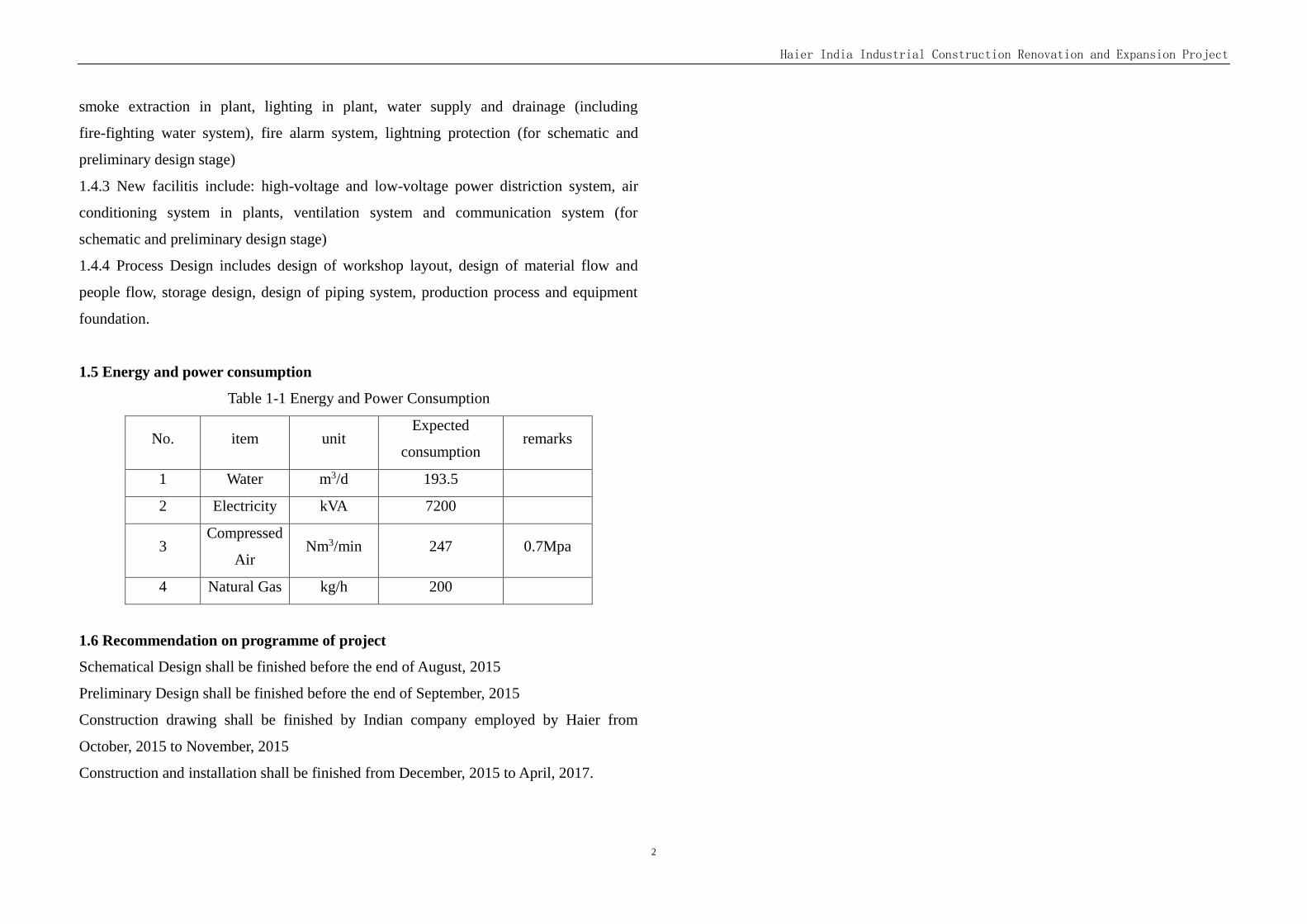
1.5 Energy and power consumption
Table 1-1 Energy and Power Consumption
No. item unit Expected
consumption remarks
1 Water m3/d 193.5
2 Electricity kVA 7200
3 Compressed
Air Nm3/min 247 0.7Mpa
4 Natural Gas kg/h 200
1.6 Recommendation on programme of project
Schematical Design shall be finished before the end of August, 2015
Preliminary Design shall be finished before the end of September, 2015
Construction drawing shall be finished by Indian company employed by Haier from
October, 2015 to November, 2015
Construction and installation shall be finished from December, 2015 to April, 2017.
Haier India Industrial Construction Renovation and Expansion Project
3
Chapter 2 General layout and Transportation
2.1 Design basis and design Scope
2.1.1 Design basis
2.1.1.1 Site measurement chart provided by the builder,Including the sidelines range,
Existing building
2.1.1.2 The general layout and vertical layout of the original construction land used by the
construction project,provided by Haier
2.1.1.3 Revised Development Control Regulation 2009 of MIDC,provided by Haier
Among them,Planning conditions for:
a. Land property:industrial land
b.FSI:≤1.0
c. Building coverage:≤50%
d. Green space rate ≥10% ;Parking area ≥10% ; Auxiliary facilities 5%
e. Building back line requirements All directions≥9m
2.1.1.4 Haier's capacity to design the project and other related design requirements
2.1.1.5 National and local regulations:
Revised Development Control Regulation 2009;
NATIONAL BUILDING CODE OF INDIA 2005;
2.1.1.7 This project locate by Relative size, Altitude by Elevation of the original building
height
2.1.2 Design basis
This project is Haier Industrial Park in India expansion project, design content include:
refrigerator plant, comprehensive workshop, Chinese apartment, cafeteria and India
apartment, high voltage power distribution room, west gate, pre mixed between, water and
industrial waste water processing station, sewage treatment station, rainwater collection
pool, LPG tank.
The production, office, logistics storage and transportation of the project and the necessary
power and road line of the project are unified planning and design.
2.2 Site summary and meteorological data
2.2.1 Site summary
This project is Haier Industrial Park of India changed expansion project, located in the
Indian state of Maharashtra Pune, India Haier plant, land area for 160000 square meters
(240 mu of contract), East Branch of the park, Park Branch is faced on the west, north near
neighboring project, South midcroad
India Haier Industrial Park project is located in the industrial area of PUNE, about 50KM
from PUNE, the location is superior, convenient transportation, perfect supporting
facilities
2.2.2 Basic data
Pune is a west city inIndia, 140 kilometers southeast of Mumbai. For Maharashtra
(Maharashtra) the second largest city, Maharashtra economic, cultural and transportation
center, capital of Pune prefectures and counties, Pune is located in Germany Deccan
Plateau in the west, moula and mu of Tarim River confluence. Now for the heavy industry
and transportation center.
Pune, about 600 meters above sea level. The climate is dry and cool, the average
temperature in January is 20, and the annual rainfall is 30 mm in May, and the annual
rainfall is 715 mm.
Pune is the thoroughfare Mumbai Yuexi Ghats and the eastern peninsula into the
mainland.
Annual mean temperature 20~30℃
Extreme maximum temperature 40.2℃
Extreme minimum temperature 5℃
Haier India Industrial Construction Renovation and Expansion Project
4
Annual average annual rainfall 300mm
Annual average relative humidity summer 10~30%, winter 20~40%, rainy season
50~80%
Dominant wind direction Westerly
2.3 General layout
2.3.1 General layout principle
According to the production requirements, combined with the status conditions within the
park, the existing buildings and new buildings, transport routes and pipeline engineering,
green facilities factors considered, co-ordination arrangements, reasonable compact were
general layout.
The production process is smooth, the material transportation route is short and convenient.
Avoid frequent flow of the logistics and the main stream of people, clean sewage
diversion.
To meet the requirements of functional zoning, various auxiliary and ancillary facilities
should be as close as possible to the workshop, a variety of power supply facilities should
be near the load center, saving investment
Strictly implement the national standards, and meet the requirements of fire, safety, health
and so on.
With the local meteorological conditions, the building has a good orientation, natural
lighting and natural ventilation, and is conducive to environmental protection.
Create conditions for the convenience of construction and business management.
2.3.2 General layout
The project total area of 160000 square meters, is a square block, the former Daewoo
project land, Haier's acquisition of local transformation and park to the south of the
existing building production plant with workshop office, the size of 280mx80m (axis), the
north for the production of auxiliary housing area, the implementation of this project
required part was removed. According to the project construction scale and product
categories, planning new two main building in the park on the north side of the building,
including a two storey AC/WM/WH Plant, with auxiliary facilities housing on the north
side of, the main plant size is 282mX90m; an one storey refrigerator plant, the size is
282mX90m; the factory set up four storey office space on the east side, on the west side
of the product loading area, near the entrance of the New Park logistics, near the existing
plant and the loading area, to facilitate unified management of logistics enterprises;
located near the entrance guard room, in the east of site land, is Dorm for Chinese Staff,
Canteen and Dorm, water supply and distribution station, on the north side of the old
building, is the new Premix Room. On the south side of the site is a large area of green,
near the park on the south side of the main entrance, as an important park landscape area,
not only for staff created a good working environment and broad career, but also greatly
enhance the overall image of the entire park. Other underground facilities are detailed in
the general layout plan, including industrial wastewater treatment station, sewage
treatment station, rainwater collection pool.
In short, the entire plant functional partition is clear, the layout is compact, the flow of
material flow is reasonable. The spacing between buildings can meet the requirements of
the fire codes for the design and the sunshine of building. See general layout plan.
2.4 Vertical layout
Because this project is re planning in the original site of park, the current situation of
terrain formation has been, the park's overall elevation approximately in about
667m~668m, existing production workshop of indoor floor elevation is 667.95m.
Considering the park's overall image and plant directly for logistics and transport
requirements, the new main building indoor floor elevation is also 667.95m, height
difference between indoor and outdoor is 0.450m, on the west side of the loading and
unloading floor design for 666.75m. The height of 1.20m as loading and unloading
Haier India Industrial Construction Renovation and Expansion Project
5
platform, also facilitate and on the west side of the peripheral road elevation docking.
This site of rain water is using Organize discharge, discharge ditch is used in the system,
back to the rainwater tanks and treated as green water.
2.5 Road system
Road is necessary for site in the organization of production, life of vehicle and pedestrian
traffic between channel, contact the site in all buildings and structures, and park and the
external environment phase coherent transport link. Park road system is using loop layout,
road around the park and buildings around, orderly, which is convenient passenger and
cargo flow, traffic organization and transportation, and can meet the requirements of
disaster prevention and evacuation. According to the different features and service object,
mainly divided into main road, secondary road, its width respectively: 12.0 meters, 4
meters, the concrete pavement, the turning radius of 12 meters and 6 meters, respectively,
to meet the park stream of people, logistics and fire requirements.
2.6 Stream of people, logistics and transportation organization plan
How to properly handle the flow of people, logistics, is the focus of the traffic
organization design. Existing park has two entrances, which: the main entrance to the
south side of the entrance is to the east, the Secondary entrance to the south side of the
entrance is to the west, theya re open to the MIDCROAD. This phase of the project the
main logistics for truck transportation of raw materials and finished product transport
truck, the park, the main stream of people for work workers, management personnel and
foreign negotiate business and visiting personnel. According to the characteristics of the
park surrounding municipal road environment, and combined with the original park is
provided with an opening, the project is on the south side of the primary and secondary
exports remain unchanged, Lord of the entrance as a pedestrian entrance, the entrance as
the import and export of raw materials and finished products, in the run-up to the plant on
the west side of the finished product unloading area, opened for goods on the west side of
the park road entrances and exits, as this phase of the project after the completion of the
product stream entrance.
In short, the flow of people in the park, logistics is relatively smooth, clear, reasonable, is
suitable for the characteristics of the enterprise.
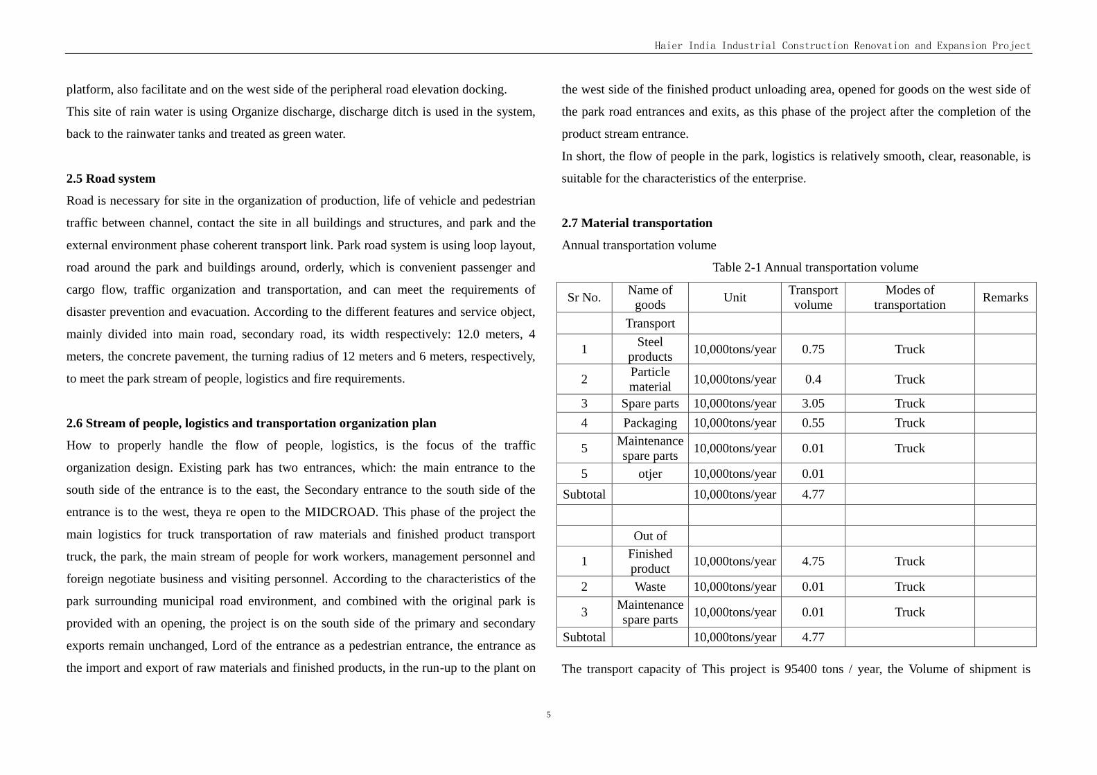
2.7 Material transportation
Annual transportation volume
Table 2-1 Annual transportation volume
Sr No. Name of
goods Unit
Transport volume
Modes of transportation
Remarks
Transport
1 Steel
products 10,000tons/year 0.75 Truck
2 Particle material
10,000tons/year 0.4 Truck
3 Spare parts 10,000tons/year 3.05 Truck
4 Packaging 10,000tons/year 0.55 Truck
5 Maintenance spare parts
10,000tons/year 0.01 Truck
5 otjer 10,000tons/year 0.01
Subtotal 10,000tons/year 4.77
Out of
1 Finished product
10,000tons/year 4.75 Truck
2 Waste 10,000tons/year 0.01 Truck
3 Maintenance spare parts
10,000tons/year 0.01 Truck
Subtotal 10,000tons/year 4.77
The transport capacity of This project is 95400 tons / year, the Volume of shipment is
Haier India Industrial Construction Renovation and Expansion Project
6
47700 tons / year, The amount shipped is 47700 tons / year.
2.7.2 Means of transport and transport
To import the raw materials, finished products Sinotrans mainly uses road transport, in
order to save investment, not purchase transportation equipment, by the company's
existing vehicle to bear since the transport part of the transport volume. The problem is
solved by social forces.
2.8 Integrated pipeline planning
2.8.1 Layout principle
2.8.1.1 The general layout of the pipeline is Synchronous with the general layout of the
industrial enterprises, the vertical design and the layout of the green. Between pipelines,
pipelines and buildings and structures is compact and reasonable in the plane, vertical
coordination,.
2.8.1.2 Pipeline laying method according to the nature of the medium in the pipeline, the
factory terrain production safety, transportation, construction maintenance and other
factors, the technical and economic comparison, the preferred.
2.8.1.3 Pipeline layout must be in order to meet the production, safety, maintenance of the
conditions for the use of land. Main trunk and pipeline using a common trench laying.
2.8.1.4 The layout of the line is parallel to the red line of the road or building.
2.8.1.5 The cross of the pipeline and the road and other main pipe be Reduce as much as
possible.
2.8.1.6 Park phased construction, pipeline layout comprehensive planning, the recent
focus, near and forward combination. In the short term, the use of the land is not affected.
2.8.1.7 When the pipeline is integrated, the main pipe is arranged on one side or the
pipeline is arranged on both sides of the road. Pipeline layout according to the following
order, from the building line to the road layout:
Telecommunication cables, power cables, all kinds of process pipeline or pipe trench,
production and living water supply pipeline, industrial wastewater (production wastewater
and production of sewage pipeline, sewage pipeline, pipeline fire, storm water drains,
lighting.
2.8.2 Integrated pipeline layout scheme
Water supply line is annular partition layout, fire water and drinking water production, set
apart. Diversion of rain and sewage, rainwater pipes and sewage pipes buried by. Strong,
weak cable and pipe are used in fuel pipe laying mode. All pipelines are laid along the
main road in the park and are delivered to the required building as needed.
2.9 Greening landscape design
2.9.1. Principles of green layout
a Greening is an important measure to protect and beautify the environment.
b Is conducive to eliminate or reduce the production process of dust, waste gas and noise
pollution of the environment, to create a good production and living environment.
c Choose plants according to local conditions, as soon as possible to play green benefits.
2.9.2 Landscape design
In the landscape design, the use of point, line, face a combination of methods, the
formation of organic landscape route. Make full use of road and the surrounding green,
combined with the form of architecture landscape layout, form a unique landscape
characteristics, to create a beautiful external environment space, form a dynamic and
organic landscape as a whole.
Front zone is the landscape of the project, it is located near the main entrance with the
green, square, flower beds as the main landscape, with the plant to form, form the
atmosphere, modern factory area. Other production areas mainly with general layout of the
site conditions, planting in the road on both sides, the surrounding buildings, natural
elevation, the side of the fence, to achieve the purpose of the background, foil factory
modern cultural atmosphere, reflects the modern enterprise.
Haier India Industrial Construction Renovation and Expansion Project
7
Building single facade modeling to form the entire park in a neat and uniform and have a
change in the face of the space effect, the shape follows the simple and smooth, and the
intensity of the principle.
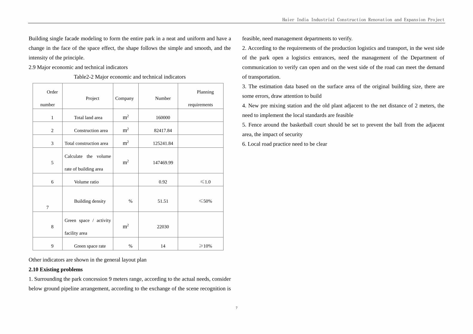
2.9 Major economic and technical indicators
Table2-2 Major economic and technical indicators
Order
number Project Company Number
Planning
requirements
1 Total land area m2 160000
2 Construction area m2 82417.84
3 Total construction area m2 125241.84
5 Calculate the volume
rate of building area m2 147469.99
6 Volume ratio 0.92 ≤1.0
7 Building density % 51.51 ≤50%
8 Green space / activity
facility area m2 22030
9 Green space rate % 14 ≥10%
Other indicators are shown in the general layout plan
2.10 Existing problems
1. Surrounding the park concession 9 meters range, according to the actual needs, consider
below ground pipeline arrangement, according to the exchange of the scene recognition is
feasible, need management departments to verify.
2. According to the requirements of the production logistics and transport, in the west side
of the park open a logistics entrances, need the management of the Department of
communication to verify can open and on the west side of the road can meet the demand
of transportation.
3. The estimation data based on the surface area of the original building size, there are
some errors, draw attention to build
4. New pre mixing station and the old plant adjacent to the net distance of 2 meters, the
need to implement the local standards are feasible
5. Fence around the basketball court should be set to prevent the ball from the adjacent
area, the impact of security
6. Local road practice need to be clear
Haier India Industrial Construction Renovation and Expansion Project
8
Chapter 3 Production Process
3.1 Design basis and design scope
3.1.1Design Basis
a. Design Contract between CEC and Haier Appliances (India) Pvt.Ltd (Contract No.:
2015 Design [107] )
b. Data and information on current production process and equipmentHaier provided by
Haier Appliances (India) Pvt.Ltd
c. Relevant Design Code:
Code for fire protection of building GB50016-2014
Technical Code for City Gas GB50028-2006
Design code for industrial metallic pipeline(2008) GB50316-2000
Specification on Complilation of Design Document of Construction Project by MOHURD
2008
NATIONAL BUILDING CODE OF INDIA 2005
d. Other data and information provided by Haier Appliances (India) Pvt.Ltd
3.1.2Design scope
Scope of production process design of Haier India Industrial Park Renovation and
Expansion Project mainly covers:
a. Workshop layout in plants
b. Design of material flow and people flow.
3.2 Product pland and production scale
Main products of Haier India Industrial Park Renovation and Expansion Projectc cover
refrigerators, air conditioners, water heaters, washing machines and TV sets. After
renovation and expansion, Haier India Industrial Park would be able to produce 1,800,000
refrigerators (current annual production: 900,000 refrigerators), 500,000 washing
machines, 500,000 water heaters, 500,000 air conditioners and 500,000 TV sets annually.
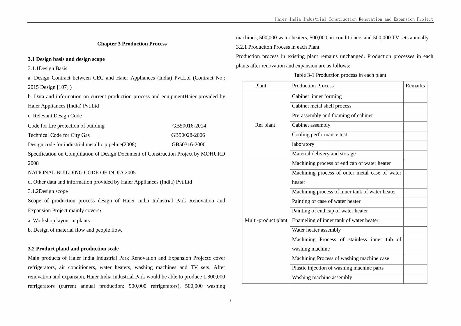
3.2.1 Produciton Process in each Plant
Production process in existing plant remains unchanged. Production processes in each
plants after renovation and expansion are as follows:
Table 3-1 Production process in each plant
Plant Production Process Remarks
Ref plant
Cabinet linner forming
Cabinet metal shell process
Pre-assembly and foaming of cabinet
Cabinet assembly
Cooling performance test
laboratory
Material delivery and storage
Multi-product plant
Machining process of end cap of water heater
Machining process of outer metal case of water
heater
Machining process of inner tank of water heater
Painting of case of water heater
Painting of end cap of water heater
Enameling of inner tank of water heater
Water heater assembly
Machining Process of stainless inner tub of
washing machine
Machining Process of washing machine case
Plastic injection of washing machine parts
Washing machine assembly
Haier India Industrial Construction Renovation and Expansion Project
9
Process of evaporator and condensor
Case Painting of AC
AC Assembly
TV set Assembly
Material delivery and storage
3.2.2 Staffing
The industrial park runs on 2 shifts/day, with a total of 2000 employees. (Managerial staff
works on 1 shift/day)
3.3 Working system
300 working days/year, 2 shifts/day, 8 hours/shift
3.4 Material flow and people flow in park
There are currently 2 gates in south boundary. The gate in southeast of the park is mainly
used for employees and the gate in southwest for material flow (for raw material and
finished goods).
After renovation and expansion, annual logistics volume in this park would reach 3
million sets. A new gate dedicated to material flow will be built in west boundary and the
existing one in southwest boundary will serve as secondary logistics gate.
3.5 The main product process
3.5.1 Refrigerator production process
(1)Case Pre-assembly
Innerliner checking——Press and stick innerliner evaporator——Temperature sensor
catheter assembly——Combine case and innerliner——Putting U shell—— Insert
innerliner into U shell——Distance star and clay fixing——Inner wires fixing and
supplementary heater assembly——Taps assembly——Door light switch assembly——
Sealing the rear panel angle——Lower steel assembly——Sealing cooling pipes——
Sealing excessive tube, R pipes —— Arrange and fix cabinets tube —— Sealing
temperature sensor——Shaping case——Cover rear panel——Fix rear panel screw——
Paste barcodes, sorting boxes outside the pipeline——Sealing self-induced switch——
Paste rear panel protective paper——Cleaning the case
(2)Pre case assembly line after case foaming
Taking protection pad——Clearing foam——Fixing the left and right forefoot plate——
Installing adjustable feet——The following hinge assembly——Compressor pallet
assembly—— Putting foam pad —— Case Cleaning ——Repairing with line ——
Compressor assembly——Fixing compressor——Putting thermostat and Installing
network block——Installing control temperature sensing tube and inserting tube——
Fixing controller unit and assemble lampshade
(3)Final assembly
Installing evaporator——Attaching the power cord to compressor pallet——Screwing
wire——Installing groud line——linking wire terminals——Terminal box assembly——
Condenser assembly——Welding high-pressure pipe and exhaust pipe——Configuring
low-pressure pipe——Welding low-pressure pipe——Welding dry filter——Drawer rails
assembly——Fixing stopper——Assemble the door and fix middle hinge——Pluging
wire into PC board and fastening——Top pannel & screw & screw cover assembly——
Electrical inspection (Inspection Lighting)——Installing PVC pipe——Cleaning interior
——Fruit and vegetable boxes, door shelves assembly——Glass shelves, wine racks
assembly——Fixing glass shelves and Installing sealed boxes——Pre-vacuum——
Vacuuming——Taking quick connector and installing damping block——Coolant
Haier India Industrial Construction Renovation and Expansion Project
10
charging——Welding and sealing tube, sorting tube——Cleaning weld——Sorting tube
and plug wire
(4)Packaging case
Paste circuit diagram nameplate——Paste the freezer door protection sponge——Paste
the energy efficiency labeling——Paste trademark nameplate and the countryside logo—
—Fixing kits——Weld painting——Fixing the press cover——Sealing door and taking
the door EPE protected cotton——Putting plastic bag——Insert corner——Sorting power
lines and sealing inside bag——Installing pat——Packing carton covering——Paste label
——Packing
(5)Door pre-assembly
Picking——Punching the door gall——Sealing——Pre-assembly——Sponge sealing—
—Pre-heating door
(6)Door assembly
Taking the door——Checking the door exterior and clearing foaming——Computer
display panel box assembly
3.6.2 Water heater production process
(1)Innerliner processing
Rolling——Straight seam welding——Flaring——Welding Pipe——Welding sewer——
Welding lug——Welding flange——Girth welding——Wall Welding——Leak detection
——Sandblasting——Enamelling——Sintering——Pre-detection
(2)Shell processing
Reeling——Straight seam welding——Pretreatment——Dusting——Removing shell
(3)Water heater assembly
Installing magnesium rod——Innerliner online——Installing heating pipe——Fixing
heating pipe——Gas detection——Leak valve assembly——Installing hanging mats
block and putting the liner pipe——Installing inlet——Innerliner and cap base assembly
——Putting foam bag——Covering shell and fixing electric wall grouding——Press shell
and cover, import and export tooling installation, installing the outlet pipe——Installing
hanging mat screw——Installing right cap and anti-electric wall lines——Installing
power line——Foaming——Clearing foam——Installing the power board and inner
cover module——Connecting wire——Installing probe——Installing sampling pipe /
ground resistance testing——Fixing installation of plate and indicators signal line——
Fixing circuit breakers——Fixing control panel module——Pluging electric wall lights—
—Installing anti-electric wall——Installing electric wall control panel——Installing red
and green ring / PC / warning labels——Installing inside and outside cover——Electrical
measurement——Stick Barcode / Cleaning——Final seizure——Paste energy efficiency
label——Boxing——Sealing packing——Finished offline
3.6.3 Product flow of washing machine
(1)Innerbarrel、outerbarrel processing
product flow of innerbarrel: Feeding——Punching——Profiled——Rolling——Buckle
side——Roll bars——Roll riveting——Fixing screws。
(2)Case assembly
feeding ——Punching——profiled——Bend1——Bend2——Punching——Welding 1
——Welding 2——feeding——Pretreatment——Dusting——unload
(3)Final assembly of washing machine
Take Case——lugs Handle assembly——Buckle base——Fastening base——power
assembly——Installation fastening line card——Stick protective pad and sponge mats—
—Mounted fastening capacitance——innerbarrel、outerbarrel assembly——Installation

Haier India Industrial Construction Renovation and Expansion Project
11
fastening the outer cylinder cover——Install the control panel——Tightening the control
panel seat——Fastening the front control panel and putting gradienter——Drain
connection——Impulse control connection——Tighten line 1——Tighten line 2——
Struck pressure cap 1——Struck pressure cap 2——Pack Protection bags——Finishing
fixed wire——Barcode stickers and nameplates——Visual inspection——Watering——
Security Comprehensive Performance Testing —— Washing performance test ——
Watering test——Leak-proof performance test——Dewatering performance testing——
Wash water residue——Stickers nameplate and energy efficiency labeling——Installation
after fastening cover——Power cable assembly——Putting tray——Rubing innerbarrel
and Installing seals——Rub washing machine cabinet —— Put washing machine
attachment——Put the barrel lining——Sleeve bags——Packing carton covering——
Sealing box——Packing——Offline。
3.6.4 Product flow of Air-conditioning
(1)Evaporator、Condenser processing
Fin punching——Expanding——Skimmed——Automatic welding——Manual welding
——Helium-leakage test
(2)Shell processing
Sheetmetal-- test——Pretreatment——Dusting——unload
(3)Final assembly of Indoor air conditioning
Installed cross-flow fan——Assembly fixed motor and Mounted evaporator assembly—
—Fixed evaporator assembly——Mounted electrical box——Fixed electrical box——
Pre-assembly of electric boards——Fixed cable and power cable——Fixed clamp——
Installed wind bracket——Extension cord——Shut electronic control board——
Extension cord——Mounted temperature sensor——Fixed pilot lamp and repair fin——
Fixed cable——Connection detected——Electrical Safety Monitoring——Performance
Testing——Assembly veil——Barcode stickers—Fixed veil and electrical cover plate—
—Assemb screw cap and affixed energy efficiency labeling——Stickers nameplate, bar
code, exemption——Pre-assembly of Accessories——Install the battery——Final test—
—Take the battery attached 3M tape——Turning machine, put the harness——Paste
harness, remote control——Inside plastic bag and EPS protecting parts assembly——
Packet bagging——Barcode stickers——Packing carton covering——Sealed box——
Packing——Offline。
(4)Outdoor components assembly
Fan bracket assembly —— Compressor assembly —— Valve plate assembly ——
Pre-condenser assembly——Condenser assembly——Motor bracket assembly——
Bulkhead assembly——Installing compressor grounding wire and pasting sponge——
Fitting tube——Welding——Wearing motor line——Installing fan——Compressor
wiring——Putting compressor jacket——Pre-installing electrical box assembly——
Electrical box assembly —— Vacuuming —— Filling —— Sealing —— Wiring ——
Temporary power line connection —— Leak detection 1 —— Security check ——
Connecting pipe——Heating performance testing——Cooling performance testing——
Leak detection 2——Cleaning and inspection——Installing right side panel——Installing
front panel—— Installing back panel—— Installing top panel——Pre-wiring cover
assembly——Installing wiring cover——Clearing exterior——Putting annex——Final
seizure——Covering bag——Casing boxed——Packing——Packaging——Offline
3.6.5 TV production process
(1)TV assembly
Haier India Industrial Construction Renovation and Expansion Project
12
Checking front case——Display inspection and installation——Installing board——
Tying and sorting cable——Aging——Image inspection——HD inspection——AV input
inspection——Sorting——Installing back shell——Pressure、insulation resistance check
——Electrical properties of the total seizure——Appearance total seizure——Packaging
3.6 Workshop Layout Discription
3.7.1 Workshop Layout in Refrigerator Plant
The planned refrigerator plant is a 1-storey building, the dimension of which is 282m*90m.
(dimension of office building is 12m*90m and dimension of production area is
270m*90m.) The refrigerator plant features a column grid of 30m*10m. Clear height of
ground floor is 8.5m. Production and process on ground floor mainly covers thermal
forming of cabinet and linner, process of metal case, pre-assembly of cabinet, cabinet
foaming, general assembly of cabinet, vacumming of cooling system, cooling performance
test and packing. For detailed information about workshop layout in refrigerator plant,
please refer to attached drawings.
3.7.2 Workshop layout in Multi-product plant
The planned multi-product plant is a 2-storey building, the dimension of which is
282m*90m. (dimension of office building is 12m*90m and dimension of production area
is 270m*90m.) Clear height of ground floor is 8.5m. For detailed information about
workshop layout in this plant, please refer to workshop layout drawing.
The ground floor is mainly for production of components and parts. Equipment is located
between axis 10 and axis 31. Area between axis 1 and axis 10 is for shipping and sorting
of finished goods.
The first floor on the planned multi-product plant is for general assembly of products.
Equipment is located in area between axis 8 and axis 22, including production equipment
for washing machine, TV set, water heater and air conditioner. Area between axis 1 and 8
is for storage and sorting of raw material.
The ground floor and first floor are connected by staircase, lift, elevator, belt conveyor and
suspension chain.
3.7 Main production equipment
3.8.1 Refrigerator production
(1)Thermal forming machine
Maximum forming size: 2000 mm ×900mm ×800 mm
Forming material: ABS or HIPS
Thickness of forming material: 2.0mm~5.0mm
Takt time: 45s (ABS), 30-45s (HIPS)
(2)Side panel process
Thickness of PCM: 0.4~0.6mm
Takt time: U shell (15s), side panel(15s)
(3)Cabinet Foaming Machine
As hazardous material is used for foaming, foaming area is equipped with hazardous gas
detector, fire alarm system and ventilation system.
(4)Door Foaming Machine
Takt time: 12.5s.
(5)Vacumming
Vacumming of cooling system involves pre-vacumming and circular on-line vacumming.
Pre-vacumming takes 1-2min and on-line vacumming takes 20min.
(6)Testing line
Test area for refrigerator includes low-pressure test, high-pressure test, and 30-min
dynamic cooling performance test.
(7)Packing line
There are totally 4 packing machines in pakcing area. Finished products are conveyed to
Haier India Industrial Construction Renovation and Expansion Project
13
warehouse through lift and overhead roller conveyer line.
(8)Labrotatory
Laboratories for type test and sample test are arranged on the first floor close to external
wall, which would cover an area of approximate 450 m2, exact area for each test room is
to be determined according to requirement in preliminary design stage. Outdoor water
cooling machine is installed on ground floor.
3.8.2 Water Heater Production
(1)Molding Line of water heater inner tank
Inner tank molding line includes rolling machine, end-expanding machine, punching
machine and welding machine. To
(2)Sand-blasting and enameling line
Inner tank of water heater is treated by process of sand-blasting and enameling. Enamel
are applied to inner surface of tank and then sinter at 850°C. Finished inner tanks are
conveyed to the first floor through suspension chain.
(3)General Assembly line
General assembly line produces products of capacity less than 40L and greater than 40L.
Takt time :72s.
3.8.3 Washing Machine Production
(1)Molding of inner tub
Molding line of inner tub includes uncoiling machine, straigntenning machine and
punching machine. Takt time:36s.
(2)General Assembly line
The general assembly line produces both fully-automatic and 2-tub machines. Takt time of
which is 36s.
3.8.4 Air Conditioner
(1)Condenssor and Evaporator
Produciton equipment of AC include 2 high-speed punching machines, 2 tube expanders, 1
degreasing machines, 1 automatic soldering line, 1 manual soldering line and 1 hydrolic
leakage test line. Takt time of the line is 36s.
(2)General Assemly line
Product of this line covers cabinet air conditioner and hanging air conditioner. General
assembly line is capable of vacumming and testing, and the takt time is 36s.
3.8.5 TV set production
(1)General Assembly line
Components and parts of TV sests are outsourced and general assembly is finished in the
plant. The TV line is 46 m long and consists of general assembly, aging test and packing
line. Takt time of the line is 36s.
3.8 Energy consumption
Energy and power for production come from existing and planned power and energy
facilities. Comsumtpion of enery and power is as follow:
No. Item Unit Consumption Ramarks
1 water m3/h 12 Treatment capacity of waste
water:10 m3/h
2 electricity kW 5000
3 Compressed air Nm3/min 75 0.6~0.7Mpa
4 Natural gas m3/h 5
5 Oxygen m3/h 4
6 Nitrogen m3/h 96
7 Circulating Water m3/h 20
Energy Consumption of Multi-product Plant:
No. Item Unit Expected Consumption Remarks
1 water m3/h 20 Waste water treatment capacity:5
m3/h
Haier India Industrial Construction Renovation and Expansion Project
14
2 electricity kW 9207
3 Compressed air Nm3/min 151 0.6~0.7Mpa
4 Natural gas m3/h 320
5 Circulating water m3/h 80
3.9 Repair and Maintenance
3.9.1 Repair and Maintenance
Repair and maintenance involves production equipment and mould (mainly plastic
injection mould and punching mould for production of evaporator and condensor), which
suffers from relatively low failure rate since they are wholly-imported or advanced
machines. Mould maintenance and repair area is arranged close to production area and
moulds are hoisted through travelling crane. Maintenance and repair is in the charge of
equipment management staff, who work on single shift (8 hours) a day. Round-the-clock
duty shall be arranged for maintenance and repair.
3.9.2 Electrical system maintenance
Electrical system maintenance (including monitoring and repair of electrical device) shall
be done in power distribution room. Overhaul and major adaption of electrical system
shall be outsourced. Tools for maintenance are commonly-used electrical devices and
instruments. Dedicated staff shall be designated to maintenance of electrical system, who
work on single shift (8 hours) a day. Round-the-clock duty shall be arranged for
maintenance and repair.
Haier India Industrial Construction Renovation and Expansion Project
15
Chapter 4 Building structure
4.1 Design basis and design scope
4.1.1 Design basis
Use requirement provided by the owner
Requirement from other disciplines
All kinds of current building laws and regulations of the People’s Republic of China
Criterion adopted in design
NATIONAL BUILDING CODEOF INDIA 2005
《Unified standard for building drawings》GB/T 50001—2010
《Standard for architectural drawings》 GB/T 50104-2010
4.1.2 Design scope
Haier India Industrial Park Renovation and Expansion Project,includ Ref
Plant,AC/WM/WH Plant,Guesthouse,Canteen and Dorn,High-volt Power Room,Premix
Room,Water Supply Station,ETP,STP,Rain Harvesting Tank. For the position of buildings
(structures) please refer to the general layout.
4.1.3 Basic data for design
See Chapter II
4.2 Building design
4.2.1 Design Scope
4.2.1.1 Location upon request from the proprietor
4.2.1.2 Everything must be confirmed by the Indian local authorities
4.2.1.3 Building shape and decoration should be kept elegant and simple but still
affordable
4.2.1.4 Building color should add to the aura of the buildings as a whole yet still have
distinct features and be easy to distinguish
4.2.2 Building and structure design of the main production plants
4.2.2.1 Indian climate can be very hot into both the dry and wet seasons – the building
should use natural ventilation and lighting to accommodate for the meteorological
characteristics as well as meet the technical production to facilitate and increase
ventilation
a. Ref Plant
A single layer, steel structure of light-weight building with gabled frames, office area
should have 4 stories, Reinforced concrete frame structure. According to Indian local
codes, building category G2 class (to be confirmed by local authorities). There should be a
4h firewall in between the office area and production areas.Plant covers an area of
25989.47 m2, with a construction area of 29457.65 m2. Basic Column grid is
10.00mx30.00m, clear height is 8.5m, height of the office area is 5.4m, 4.5m, 3.8m .no
travelling crane .The plant on the west side with a cargo handling area should be set 5m
wide with a loading platform and canopy for easy loading and unloading.
According to the requirements set by the NATIONAL BUILDING CODE OF INDIA
2005, the evacuation outlet should be set to meet the largest evacuation distance of 67.5 m
and a total of staircases (and must set up an automatic fire-distinguishing system).
b.AC/WM/WH Plant
Two storeys, steel-structured, office area should have 4 storeys, somewhere with a
auxiliary building, Reinforced concrete frame structure. According to Indian local codes,
building category G2 class (to be confirmed local authorities). There should be a 4h fire
wall in between the office area and production areas.Plant covers an area of 27026.9 m2,
with a construction area of 62380.68 m2. Basic Column grid is 10.00mx15.00m (7.5m),
plant height 9.9m, 7.2m, height of the office area is 5.4m, 4.5m, 3.8m. The 1-8 axes area
of plant floor should have a steel platform. with a travelling crane the first floor
between 11~16 axex.The plant on the west side with a cargo handling area should be set
5m wide with a loading platform and canopy for easy loading and unloading.
Haier India Industrial Construction Renovation and Expansion Project
16
According to the requirements set by the NATIONAL BUILDING CODE OF INDIA
2005, the evacuation outlet should be set to meet the largest evacuation distance of 67.5 m
and a total of 8 staircases (and must set up an automatic fire-distinguishing system).
c. Guesthouse
Three storeys above ground, and must accommodate staff and catering and Chinese
management construction category A3 (local authorities still need to confirm). Reinforced
concrete frame structure, covering 566.82 m2 with building area of 1814.43 m2 The height
of all storeys being 3.6 m with a total height of 13.4 m. The maximum occupancy being 32
people. Set two staircases, one with a metal ladder.
d. Canteen and dorm
Three storeys. For the Indian management, staff and catering. With maximum occupancy
of 580 people in the canteen.Building category A4 (local authorities still need to confirm).
Reinforced concrete frame structure, covering1703.07 m2 with building area of 3695.42
m2 the height of all stories being 4.5m, 3.6, 3.6m. 38 total rooms. Three flights of stairs,
evacuation distance and width are to meet regulatory requirements.
e. Auxiliary Building
Include High-volt power room, premix room, water supply station, ETP, STP, Rain
harvesting tank. A single layer of reinforced concrete-frame structure building category
G2, G3 (to be confirmed by local authorizes). see list of building structures.
4.2.2.2 Building Façade design and color
Existing buildings are to be retained within the park, with original construction type and
use of materials to match that of the new factory. This new factory building must maintain
the color and style. When possible the old and new plants should be unified with the same
façade and color.
4.3 Firefighting
The park firefighting must be in accordance with the pre-set regulations of the
NATIONAL BUILDING CODE of INDIA 2015 (design to be confirmed by local
authorities).
4.4 Building measures
4.4.1 Lighting
Consider the full use of natural light through the use of windows for energy conservation.
The natural light, however, cannot fully meet all functionality requirements and must be
supplemented by artificial lighting to meet the people’s production and life lighting needs.
4.4.2 Air Circulation
Combine the concept of natural and mechanical ventilation to meet ventilation
requirements. If the toilet and lavatory natural ventilation cannot fully meet their
functional requirements, increase the mechanical ventilation by means of the ventilation
chamber.
4.5 Building construction
The building’s exterior and interior walls should be made 120 [thick] bricks or 240 bricks
thick (unless otherwise stated).Fire safety requirements of the firewall require clay brick
masonry.The rest are as follows:
4.5.1 Roof
W1: waterproof membrane reinforced concrete with insulation Master roof for office,
dormitory, part of auxiliary building roof
W2: waterproofing membrane with insulation reinforced concrete is not accessible roof
for the guard.
W3: light steel roofing with insulation, roofing surface color steel for the plant, for plant
and Premix Room
4.5.2 Floor
Floor 1: Concrete sealer, for production plant and auxiliary building.
Haier India Industrial Construction Renovation and Expansion Project
17
Floor 2: Non-slip tiles for the bathroom.
Floor 3: Ceramic tile, for dormitories, hall, stairwells and other public areas.
Floor 4: Anti-static overhead for the fire control room and the telephone network room.
4.5.3 Interior decoration:
N1: Paint interior walls: general construction for the park within the walls.
N2: Wall tiles inside for toilets, wash rooms and other inside the wall.
4.5.4 Exterior decoration: exterior paint for the park quarters, auxiliary building outside
the walls of the building. Color steel outer walls, for plant.
4.5.5 Door and window
4. 5.5.1 Door
a. Office entrance hall will be equipped with electric sensing glass doors.
b. Plant offices, reception hall, etc. will be installed with 1200 to 1500 wooden doors
c. Toile and bathroom will be equipped with wood doors, the doors shall be equipped with
ventilation louvers.
d. Plant gate shall be equipped with electric roll-up door and flat-open door, the door
where raw materials and finished products will be in and out shall be vertical lifting door.
4. 5.5.2 Window
a. Outside windows without special note shall be Series 80 plastic-steel windows. (5mm
thick float glass); If any specially notes, please see the notes in design. The low windows
are installed with stainless steel anti-theft network; Louver in the basement will be
installed with steel mesh not more than 10x10.
b. Windows with special requirement see details in design
4.5.6 Toilet room
4.5.6.1 Interior wall will be fitted with200 × 300 white wall tiles, partition is plastic
partition h =1.80m with small door of 600mm width, and logo inner fastener on the door.
4. 5.6.2 Equipped with sitting wc pan
4.5.6.3 Black granite panels is adopted for washing table, h = 800, equipped with a mirror.
4. 5.6.4 Aluminium & plastic plate ceiling
4.5.7 balustrades: the foyer steel railing with tempered glass, the rest are made of stainless
steel railings.
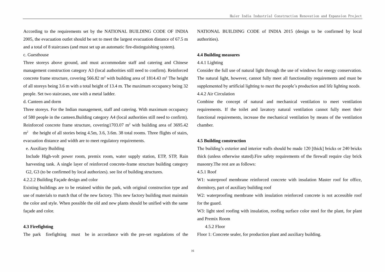
Table 4-1 Buildings and Structures Table
Item Plane size m × m
Covered area
(m2)
Building
area (m2)
Fire danger in
production (storage)
Column Network
size (m×m)
Structure form
Column top elevation and storey
height(m)
Remark
Ref Plant
282 x 90 25989.4
7 29457.65 G2
Plant: 10 ×30
Office area: 12 ×7.5
steel-structured Reinforced
concrete frame structure
Plant: 9.9
Office area: 5.4,4.5, 3.8,3.8
AC/WM/WH Plant
282 x 98 27026.9 62380.68 G2
Plant: 10 ×30(15) Office area: 12 × 7.5
steel-structured Reinforced
concrete frame structure
Plant: 9.9,7.2
Office area: 5.4,4.5, 3.8,3.8
Guesthouse
29 x 22.8
566.82 1814.43 A3 5.8~7.2×3.6~4.8
Reinforced concrete frame
structure 3.6
Canteen and
Dorn
27.3 x 61.6
1703.07 3695.42 A4 7.2×8 Reinforced
concrete frame structure
4.5,3.6,3.6
High-volt Power Room
16.5x18 305.34 305.34 G2 8.25 × 6 Reinforced
concrete frame structure
5.5
West Guardro
om 15.6x5 76.12 76.12 G1 4~6×5
Reinforced concrete frame
structure 3.5
Premix Room
30 x 9 279.42 279.42 G3 7.5 × 9 Reinforced
concrete frame structure
5.5
Water Supply Station
28x8 232.70 232.70 G1 8 × 8 Reinforced
concrete frame structure
7
ETP 180 G1 Reinforced
concrete frame structure
STP 180 G1 Reinforced
concrete frame structure
Water Supply Station
132 G1 Reinforced
concrete frame structure
Gas Tank
45
TOTAL 56917.84 98241.84
Haier India Industrial Construction Renovation and Expansion Project
18
Chapter 5 Structure design
5.1 Project overview
5.1.1 The project is located in B-3, Ranjangaon Growth Centre, MIDC Ranjangaon, Tal:
Shirur, Dist:Pune, Maharashtra State, India.
5.1.2 According to process layout and general layout planning requirements,the project
include Ref Plant, AC/WM/WH Plant, Guesthouse, Canteen and Dorn, High-volt Power
Room, Premix Room, Water Supply Station, ETP, STP, Rain Harvesting Tank.
5.2 Design basis
5.2.1 Design use-life of the project is 50 years.
5.2.1 Natural conditions
a. The reference wind pressure (Return period of 50 years): Basic wind speed is 39m/s.
b. The reference snow pressure (Return period of 50 years):0.
c. Seismic fortification intensity
According to MAP OF INDIA SHOWING SEISMIC ZONES OF INDIA, the project site
seismic zone of Ⅲ, Z=0.16.
5.2.3 Relevant documentation provided by Process, architecture professionals
5.2.4 Relevant design standards
NATIONAL BUILDING CODE OF INDIA 2005
Reference chinese standard
Code of Design on Building Fire protection and prevention GB 50016-2014
Code for design of masonry structures GB50003-2011
Code for design of building foundation GB 50007-2011
Load code for the design of building structures GB 50009-2012
Code for design of concrete structures GB50010-2010
Code for seismic design of buildings GB50011-2010
Code for design of steel structures GB50017-2003
Technical specification for steed structure of light-weight Buildings with gabled frames
CECS 102:2002(2012version)
Code for investigation of geotechnical engineering GB50021-2001(2009version)
Unified standard for reliability design of building structures
GB50068-2001
Standard for classification of seismic protection of building constructions
GB50223-2008
Other existing national codes and standards.
5.3 Building classification
5.3.1 According to”Code for design of concrete structures”GB50010-2010, safety grade of
building structure is Grade 2.
5.3.2 According to”Standard for classification of seismic protection of building
constructions”GB50223-2008, Seismic fortification category of the project are standard.
5.3.3 Seismic level reinforced concrete frame structure is Grade 3. Seismic level steel
frame structure is Grade 4.
5.3.4 Design grade of groundsill foundation is tentatively Grade C
5.4 The main load values
5.4.1 Floor load
According to “Load code for the design of building structures”GB 50009-2012, Combined
with the practical engineering, floor live load standard value is determined as follows:
Floor AC/WM/WH Plant 8.0kN/m2
Factory ground load 50 kN/m2
Office area:
Fixed partition Office 2.0kN/m2
No fixed partition Office 3.5kN/m2
Haier India Industrial Construction Renovation and Expansion Project
19
Computer Room 3.5kN/m2
File storage room 5.0kN/m2
Corridors, stairways, halls 4.0kN/m2
Toilet 2.5kN/m2
Canteen:
Restaurant 4.0kN/m2
Kitchen 4.0kN/m2
Balcony 4.0kN/m2
Corridors 3.5kN/m2
Stairways 3.5kN/m2
Elevator machine room 7.0kN/m2
Toilet 2.5kN/m2
Dorm room:
Room 2.0kN/m2
Corridors 3.0kN/m2
Stairways 3.5kN/m2
Balcony 3.0kN/m2
Master roof 2.0kN/m2
Exalted roof 0.5kN/m2
The other value by "Load code for the design of building structures"GB50009-2012
5.4.2 Anti-floating design water level of the project site is outdoor ground level -0.5m.
5.5 Design of superstructure
Refrigerator Plant plane size is 282x90m, the east side of 12x90m section is the office area.
Proposed to establish one vertical joints, the plant is divided into two parts: 270x90m,
12x90m. Which 270x90msector is the production area. Production area is one-layer,
column grid: 10.00mX30.00m, the height of beam bottom of the workshop is 8.5m.
Structure is steel structure of light-weight building with gabled frames. Set cargo handling
area the plant on the west side, set 5m wide loading platform and canopy. 4 floor office
area, column grid is 12.00x7.5m, respectively storey 5.4m, 4.5m, 3.8m, 3.8m. Structure is
reinforced concrete frame structure.
AC/WM/WH Plant plane size is 282x90m, the east side of 12x90m section is the office
area. Proposed to establish four vertical joints, the plant is divided into five parts: 70x90m,
70x90m, 70x90m, 60x90m, 12x90m. Which 70x90m, 70x90m, 70x90m, 60x90m sector is
the production area. 70x90m area west of the production area is three layers, the height is
5.5m, 4.4m, 7.2m, the remaining area is two layers, the height is 9.9m, 7.2m, Column grid:
the first layer is 10.00mX15.00m; the second layer is 10.00mX30.00m, structure is steel
frame construction. Set cargo handling area the plant on the west side, set 5m wide
loading platform and canopy. 4 floor office area, column grid is 12.00x7.5m, respectively
storey 5.4m, 4.5m, 3.8m, 3.8m.Office and auxiliary building is reinforced concrete frame
structure.
Other buildings are reinforced concrete frame structure. See the list of specific size and
storey new building.
5.6 Foundation plan
According to details of the proposed site survey report, a building intended use
independent foundation under column. Foundation bearing stratum is strongly weathered
rock or weathered rock. Foundation bearing capacity is 450KN / m2.
5.7 Selection of main structural materials
Concrete: foundation cushion is M15; foundation is M25; upper structure(Beams, plates,
columns) is of M25.
Cement will be ordinary silicate cement.
Steel bar will be IS432 Fe250 and IS1786 Fe415. Rebar diameter specifications: 8、10、
Haier India Industrial Construction Renovation and Expansion Project
20
12、16、20、25.
Main steel will be IS2062 E350. Purlin will be processed and formed with hot-dip
galvanized sheet (E350), galvanizing volume is required to be not less than 275g/ m2 for
double sides. Coating standard is Grade A.
Masonry: ± 0.000m below the wall will be use brick and masonry cement mortar. ±
0.000m above the wall to see the building plans.
Chapter 6 Power Supply
6.1 Design scope
According to the information supplied by the relevant disciplines, this Haier India
Industrial Park includes Ref Plant, AC/WM/WH Plant, Guesthouse, Canteen and Dorn,
High-volt Power Room, Premix Room, Water Supply Station, ETP, STP, Rain Harvesting
Tank.
This design covers the power, lighting, lightning protection and grounding design for all
the plants of the project.
Demarcation point for the design scope is the power feed line-side switch cabinets of the
High-volt Power Room, and the 22kV line of this power side is not included in this design.
6.2 Power supply and distribution system
6.2.1 Class of load and Calculated load
The main electrical equipment includes spray painting, plastic sheet extrusion,
thermoforming machine, cabinet door foaming, general assembly equipment, air
compressor, fans, water pumps, lighting for buildings, etc. Power load is the Class 3.
The fire-fighting equipment (including fire elevator, fire control room equipment),
premixed, foaming area safety fan Power, etc. Power load is the Class 2.
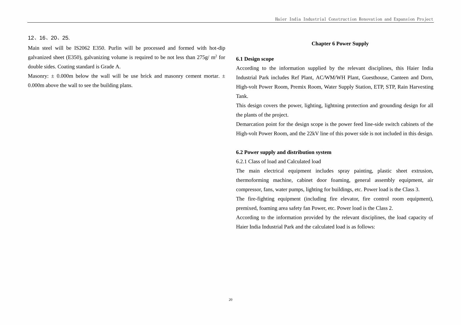
According to the information provided by the relevant disciplines, the load capacity of
Haier India Industrial Park and the calculated load is as follows:
Haier India Industrial Construction Renovation and Expansion Project
21
Power load list
6.2.2 Power supply, power supply circuit and the voltage grade
A 22kV power line was supplied for this Haier India Industrial Park, the power supply
capacity is 5000kVA, the current load is 3000kVA. This project plans to re-lead one 22kV
power line supply.
The power of fire-fighting equipment from the plant substation room two different
low-voltage bus lines, dual power switch in the end of power line. Emergency lighting
lamps self-include battery.
Power supply voltage is 22kV/380V/220V.
Power supply frequency is 50Hz.
6.2.3 Plans for Power Supply
1. This project plans to construct a new High-volt Power Room in the park, which
includes 22kV Distribution Room, Control room and bedroom. The old 22kV cabinets
move to the new High-volt Power Room. The 22kV system will adopt a single bus bar
sectionalized with bus coupler and bus tie.
2. Install a substation in the Ref plant, two 1600kVA 22/0.38/0.22kV transformers and the
corresponding low voltage distribution panels. The two incoming lines of the Ref Plant
substation are supplied by the High-volt Power Room.
3. Install a substation in AC/WM/WH Plant, which includes three 2000kVA
22/0.38/0.22kV transformers and the corresponding low voltage distribution panels. The
three incoming lines of the AC/WM/WH Plant substation are supplied by the High-volt
Power Room.
4. The power supply for the other constructions such as: Guesthouse, Canteen and Dorn,
Water Supply Station, adopt 0.38kV power cable from nearby substation.
Set the connection on the low-voltage side of the transformer in the plant, two sections of
bus bar operation respectively. The low voltage side set up centralized dynamic reactive
power compensation device, after compensation the high voltage side power factor COS
Φ>0.95.
Power supply for the plant shall be three-phase and five-wire system (0.4/0.23kV, 50Hz),
which includes 3 phase lines (A, B and C), 1 netural line (N) and 1 ground line (PE).
Equipment power supply box and lighting power supply box shall be installed indepently.
Equipment power supply box features a input power supply of three-phase (0.4kV) and the
latter a input power supply of three-phase (0.4Kv) or single-phase (0.23kV).
6.2.4 Measurement method
The total kWh meter set in the low-voltage side of the transformer, the lighting and power
distribution were measured respectively.
6.3 Lighting system
The Lighting branch line using BV-750 wire across galvanized steel pipe, lays along the
column, wall and roof.
The Plant adopt high efficient factory light fittings with metal halide lamp, the office adopt
louver type light fittings with fluorescent lamp.
The power distribution room and fire-control room set emergency lighting (90 minutes).
Plants set emergency lighting and exit lighting which along the exit aisle, office set
emergency lighting and exit lighting in the aisle and enclosed staircase (30 minutes),
selection of self-include battery lighting lamps.
Haier India Industrial Construction Renovation and Expansion Project
22
The illumination of each region:
Production area 200lx
Power distribution room 200 LX
Office / conference room 300 LX
Warehouse 100 LX
6.4 Lightning protection and ground connection
6.4.1 22kV system will adopt Neutral point and unearth system, and 0.38kV system will
adopt TN-S system.
6.4.2 Lightning protection belt is laid along parapet walls around the roof of buildings,
steel roofing (≧0.5mm) is adopted to prevent direct lightning strike and inner steel bars or
steel pillars are adopted as leading wire. Inner steel bars of foundation are equipped with
ground connection devices.
Separate independent buildings are equipped with surge protection and common
equipotential connection at incoming points, and partial equipotential connection for toilet.
6.4.3 Building lightning protection and grounding, power distribution system working
grounding, protective grounding and the weak electricity system grounded altogether,
grounding resistance will be less than 1 ohm. The buildings grounding devices are
connected to each other.
6.5 Electrical energy saving measures
6.5.1 Energy saving measures for power distribution system
Power substation set near the load center, which reduces the length of the power cable and
the line loss.
All electrical equipment adopts energy-saving products, reduce the equipment loss.
Equilibrium distribution of single-phase equipment, make three-phase load balance.
6.5.2 Lighting system energy-saving measures
High efficiency and energy-saving lamps are selected in the project. The Plant adopt metal
halide lamp, the office adopt fluorescent lamp.
The lamps are provided with capacitor compensation, the power factor is not less than 0.9
after compensation.
The lighting adopts general lighting in combination with local lighting in the production
line.
The stairs and aisle adopt energy-saving self-extinguishing switch.
Road lighting adopts manual control, luminance control, time control and other control
methods.
Haier India Industrial Construction Renovation and Expansion Project
23
Chapter 7 Water supply and drainage
7.1 Design basis
Water supply and drainage design data provided by the owner and the other professionals
India's architectural design specification (2005 edition)
Code for design of building water supply and drainage GBJ50015-2003 (2009)
Code for design of outdoor water supply engineering GB50013-2006
Code for design of outdoor wastewater engineering GB50014-2006 (2014)
Code for fire protection design of buildings GB50016-2014
Code of design for sprinkler systems GB50084-2001 (2005)
Code for design of extinguisher distribution in buildings GB50140-2005
Technical code for fire protection water supply and hydrant systems GB50974-2014
7.2 Design scope and basic data
7.2.1. Design range
Production water supply and drainage、 living water supply and drainage and fire
protection water supply engineering design.
7.3 Water supply
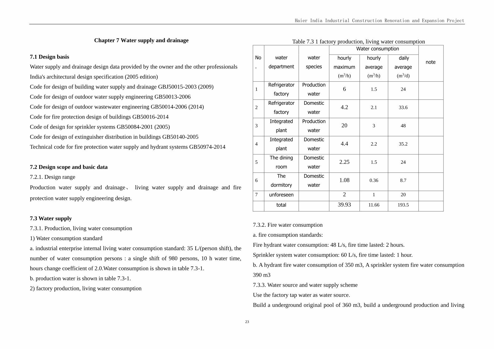
7.3.1. Production, living water consumption
1) Water consumption standard
a. industrial enterprise internal living water consumption standard: 35 L/(person shift), the
number of water consumption persons : a single shift of 980 persons, 10 h water time,
hours change coefficient of 2.0.Water consumption is shown in table 7.3-1.
b. production water is shown in table 7.3-1.
2) factory production, living water consumption
Table 7.3 1 factory production, living water consumption
No
.
water
department
water
species
Water consumption
note hourly
maximum
(m3/h)
hourly
average
(m3/h)
daily
average
(m3/d)
1 Refrigerator
factory
Production
water 6 1.5 24
2 Refrigerator
factory
Domestic
water 4.2 2.1 33.6
3 Integrated
plant
Production
water 20 3 48
4 Integrated
plant
Domestic
water 4.4 2.2 35.2
5 The dining
room
Domestic
water 2.25 1.5 24
6 The
dormitory
Domestic
water 1.08 0.36 8.7
7 unforeseen 2 1 20
total 39.93 11.66 193.5
7.3.2. Fire water consumption
a. fire consumption standards:
Fire hydrant water consumption: 48 L/s, fire time lasted: 2 hours.
Sprinkler system water consumption: 60 L/s, fire time lasted: 1 hour.
b. A hydrant fire water consumption of 350 m3, A sprinkler system fire water consumption
390 m3
7.3.3. Water source and water supply scheme
Use the factory tap water as water source.
Build a underground original pool of 360 m3, build a underground production and living
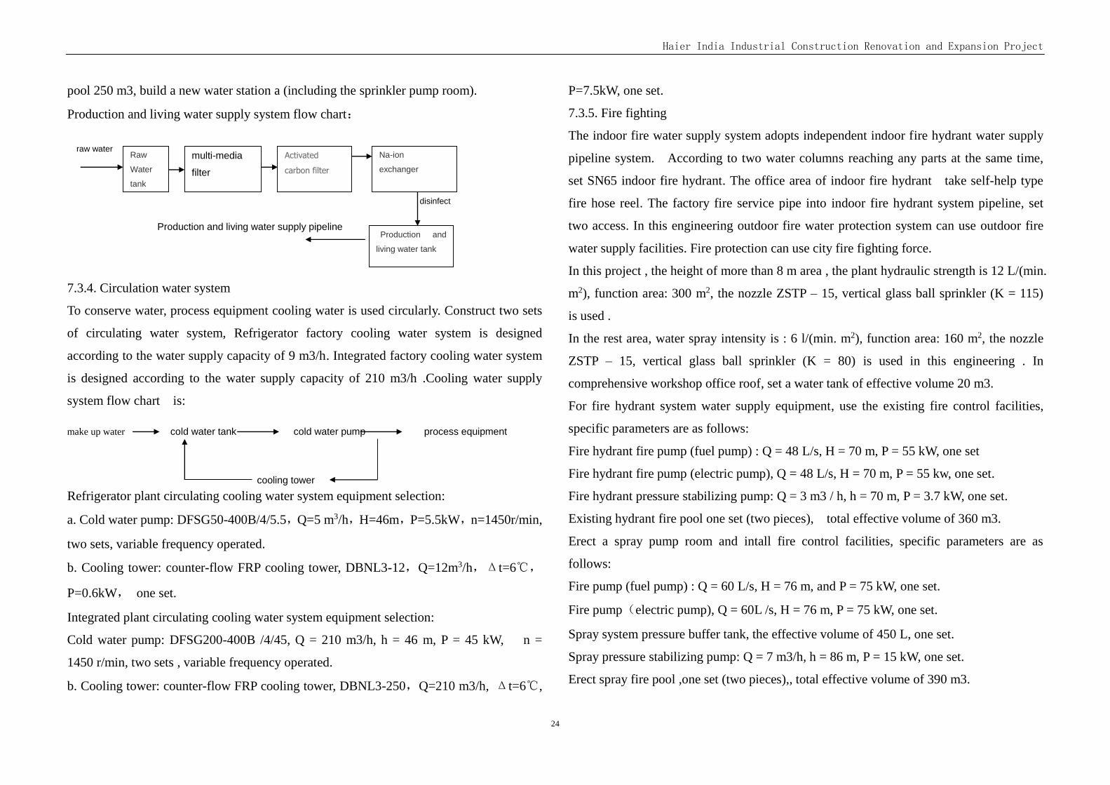
Haier India Industrial Construction Renovation and Expansion Project
24
pool 250 m3, build a new water station a (including the sprinkler pump room).
Production and living water supply system flow chart:
raw water
disinfect
Production and living water supply pipeline
7.3.4. Circulation water system
To conserve water, process equipment cooling water is used circularly. Construct two sets
of circulating water system, Refrigerator factory cooling water system is designed
according to the water supply capacity of 9 m3/h. Integrated factory cooling water system
is designed according to the water supply capacity of 210 m3/h .Cooling water supply
system flow chart is:
make up water cold water tank cold water pump process equipment
cooling tower
Refrigerator plant circulating cooling water system equipment selection:
a. Cold water pump: DFSG50-400B/4/5.5,Q=5 m3/h,H=46m,P=5.5kW,n=1450r/min,
two sets, variable frequency operated.
b. Cooling tower: counter-flow FRP cooling tower, DBNL3-12,Q=12m3/h,Δt=6℃,
P=0.6kW, one set.
Integrated plant circulating cooling water system equipment selection:
Cold water pump: DFSG200-400B /4/45, Q = 210 m3/h, h = 46 m, P = 45 kW, n =
1450 r/min, two sets , variable frequency operated.
b. Cooling tower: counter-flow FRP cooling tower, DBNL3-250,Q=210 m3/h, Δt=6℃,
P=7.5kW, one set.
7.3.5. Fire fighting
The indoor fire water supply system adopts independent indoor fire hydrant water supply
pipeline system. According to two water columns reaching any parts at the same time,
set SN65 indoor fire hydrant. The office area of indoor fire hydrant take self-help type
fire hose reel. The factory fire service pipe into indoor fire hydrant system pipeline, set
two access. In this engineering outdoor fire water protection system can use outdoor fire
water supply facilities. Fire protection can use city fire fighting force.
In this project , the height of more than 8 m area , the plant hydraulic strength is 12 L/(min.
m2), function area: 300 m2, the nozzle ZSTP – 15, vertical glass ball sprinkler (K = 115)
is used .
In the rest area, water spray intensity is : 6 l/(min. m2), function area: 160 m2, the nozzle
ZSTP – 15, vertical glass ball sprinkler (K = 80) is used in this engineering . In
comprehensive workshop office roof, set a water tank of effective volume 20 m3.
For fire hydrant system water supply equipment, use the existing fire control facilities,
specific parameters are as follows:
Fire hydrant fire pump (fuel pump) : Q = 48 L/s, H = 70 m, P = 55 kW, one set
Fire hydrant fire pump (electric pump), Q = 48 L/s, H = 70 m, P = 55 kw, one set.
Fire hydrant pressure stabilizing pump: Q = 3 m3 / h, h = 70 m, P = 3.7 kW, one set.
Existing hydrant fire pool one set (two pieces), total effective volume of 360 m3.
Erect a spray pump room and intall fire control facilities, specific parameters are as
follows:
Fire pump (fuel pump) : Q = 60 L/s, H = 76 m, and P = 75 kW, one set.
Fire pump(electric pump), Q = 60L /s, H = 76 m, P = 75 kW, one set.
Spray system pressure buffer tank, the effective volume of 450 L, one set.
Spray pressure stabilizing pump: Q = 7 m3/h, h = 86 m, P = 15 kW, one set.
Erect spray fire pool ,one set (two pieces),, total effective volume of 390 m3.
Raw
Water
tank
multi-media
filter
Activated
carbon filter Na-ion
exchanger
Production and
living water tank
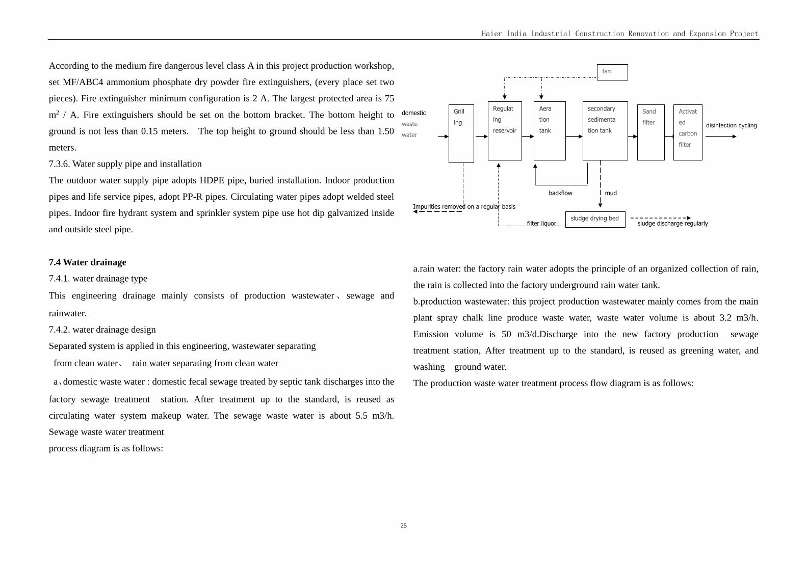
Haier India Industrial Construction Renovation and Expansion Project
25
According to the medium fire dangerous level class A in this project production workshop,
set MF/ABC4 ammonium phosphate dry powder fire extinguishers, (every place set two
pieces). Fire extinguisher minimum configuration is 2 A. The largest protected area is 75
m2 / A. Fire extinguishers should be set on the bottom bracket. The bottom height to
ground is not less than 0.15 meters. The top height to ground should be less than 1.50
meters.
7.3.6. Water supply pipe and installation
The outdoor water supply pipe adopts HDPE pipe, buried installation. Indoor production
pipes and life service pipes, adopt PP-R pipes. Circulating water pipes adopt welded steel
pipes. Indoor fire hydrant system and sprinkler system pipe use hot dip galvanized inside
and outside steel pipe.
7.4 Water drainage
7.4.1. water drainage type
This engineering drainage mainly consists of production wastewater、 sewage and
rainwater.
7.4.2. water drainage design
Separated system is applied in this engineering, wastewater separating
from clean water、 rain water separating from clean water
a、domestic waste water : domestic fecal sewage treated by septic tank discharges into the
factory sewage treatment station. After treatment up to the standard, is reused as
circulating water system makeup water. The sewage waste water is about 5.5 m3/h.
Sewage waste water treatment
process diagram is as follows:
泵 disinfection cycling
外排
c
backflow mud
Impurities removed on a regular basis
filter liquor sludge discharge regularly
a.rain water: the factory rain water adopts the principle of an organized collection of rain,
the rain is collected into the factory underground rain water tank.
b.production wastewater: this project production wastewater mainly comes from the main
plant spray chalk line produce waste water, waste water volume is about 3.2 m3/h.
Emission volume is 50 m3/d.Discharge into the new factory production sewage
treatment station, After treatment up to the standard, is reused as greening water, and
washing ground water.
The production waste water treatment process flow diagram is as follows:
Grill
ing
栅
井
井
Regulat
ing
reservoir
池
Aera
tion
tank
secondary
sedimenta
tion tank
Sand
filter
sludge drying bed
fan
domestic
waste
water
Activat
ed
carbon
filter
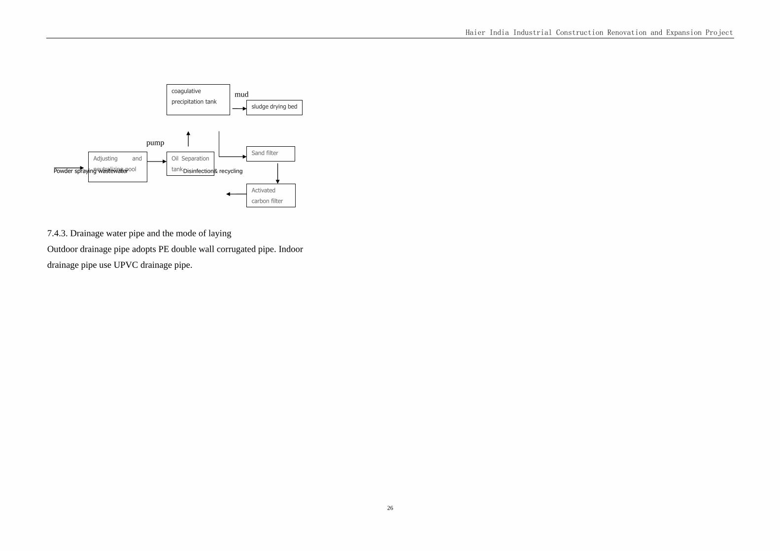
Haier India Industrial Construction Renovation and Expansion Project
26
Sand filter
Activated
carbon filter
器
Oil Separation
tank
Adjusting and
neutralizing pool
mud
pump
Powder spraying wastewater Disinfection& recycling
7.4.3. Drainage water pipe and the mode of laying
Outdoor drainage pipe adopts PE double wall corrugated pipe. Indoor
drainage pipe use UPVC drainage pipe.
coagulative
precipitation tank sludge drying bed
Haier India Industrial Construction Renovation and Expansion Project
27
Chapter 8 Ventilation and Air Conditioning System
8.1 Basis for design
1)NATIONAL BUILDING CODEOF INDIA 2005
2) Refer to Chinese standard
‘Code for Design Of Heating, Ventilation and Air Conditioning’
‘Code for Heating, Ventilation and Air Conditioning in Civil Construction’
‘Fire-prevention Code for Construction Design’
3) The demand of the owner and the design information from other disciplines
8.2 Scope of design
1)The ventilation system, fire venting system, evaporative cooling for the plant.
2)The ventilation for auxiliary rooms of production.
3)The ventilation and AC for office and residential architecture.
8.3 Design parameter
1)meteorologic parameter(India PATNA)
Cooling DB 37.4℃
Cooling WB 20.4℃
Heating DB 10.3℃
Heating WB 9.2℃
2)inside design conditions
office building:
summer inside design condition 23~26℃
winter inside design condition 21~23℃
cabinet foam area ,texting room:
summer inside design condition 28℃
winter inside design condition 22℃
8.4 Ventilation & evaporative cooling
8.4.1 Refrigerator Plant&AC/WM/WH Plant
1)Refrigerator Plant
The plants is all steel-farmed .There are one floor in the workshop with four- floors
Office.The building size is about 282m×90m, the height of beam bottom of the workshop
is 8.5m .There will be ventilationsystems in the workshop .
the nature exhausting system and supplying system would be set in the workshop
with replenish supplied fresh air natural.
A large part of the fresh air supplied by evaporative cooling units, which can make
the air cooler and moister.The grilles would be set right above the operating workers or
may be evently distributed over the workshop.Parts of the fresh air supplied through
windows or doors, there are lovers on the bottom of the external walls which having rain
protection profile and could be shuteed when it needed.
The heat, toxic or hazardous air would be exhausted outside through the roof monitor.
2)AC/WM/WH Plant
The plant is steel-farmed .There are two floors in the workshop with four- floors
Office.The building size is about 282m×90m, the height of beam bottom of the first floor
is 8.5m and,the height of beam bottom of the second floor is 6m.
There will be ventilationsystems in the workshop .The exhausting systems will be
sonsiderated with fire venting systems.
In the first floor, the mechanical exhausting system and supplying system would be
set in the workshop with replenish supplied fresh air natural.
Parts of the fresh air supplied by evaporative cooling units, which can make the air
Haier India Industrial Construction Renovation and Expansion Project
28
cooler and moister.The grilles would be set right above the operating workers or may be
evently distributed over the workshop.Parts of the fresh air supplied through windows or
doors, there are lovers on the bottom of the external walls which having rain protection
profile and could be shuteed when it needed.
The heat, toxic or hazardous air would be exhausted through the vertical duct by the
centrifugal fan above the roof. The ventilation rate is 2~4 changes per hour.
In the second floor , the mechanical suppyingsystem and natural exhausting system
would be set in the workshop with replenish supplied fresh air natural.
Parts of the fresh air supplied by evaporative cooling units, which can make the air cooler
and moister.The grilles would be set right above the operating workers.Parts of the fresh
air supplied through windows or doors, there are lovers on the bottom of theexternal walls
which having rain protection profile and could be shut when it needed.
The heat, toxic or hazardous air would be exhausted outside through the roof monitor.
3)There are exhaust hoods upon the welding posts for manufacture. The exhaust gas
would be filtered through thedust collector.The filtered air would be lead to high altitude.
4)The exhaust gas from cabinet foam area and cooling agent injection area inrefrigerator
plant would be lead to high altitude by centrifugal fan above the roof.
5)The heat from powder coating line ,enamel wire line and injection area wouldbe exaust
by localmechanicalventilation.The ventilation rate should be calculated according to the
heat.The exhaust air would be lead to high altitude.
8.4.2 Production auxiliary room
1)Mechanical ventilation would be set in the bathroom. The ventilation rate is 8~10
changes per hour by ceiling fans.
2)Mechanical ventilation would be set in the CA station, substation room, water pump
house , elevator machine room,etc. The ventilation rate is 7~12 changes per hour by axial
fans on the external wall.
3)Emergency ventilation would be set in Pre mixing station,it can also work in normal
times. The ventilation rate is 12 changes per hour . explosion-proof should be startedwhen
the the concentration of combustible gas detection alarming.The electric switch would be
set indoor and outdoor where could be operated conveniently.
8.5 Smoke and fire venting
8.5.1Refrigerator plant /AC/WM/WH plant
Classification of the two plant is G2.
Curtain Boardsshall be of sheet metal or any othersubstantial non-combustible material,
and beam could be used as also.The curtained areas shall be limited to amaximum of 500
m2.
There are vents in all curtained areas and it connect with firesafe fans by steel duct in the
first floor of the AC/WM/WH plant.The firesafe fan could running at least 30mins under
280℃,and it would be set on the roof.It is recommended that smoke exhaust equipment
should have a minimumcapacity of 120 m³/h .m2x the area which is the lagest area that
the fan seved.
Roof monitors are used for smoke exhausting on the second floor of AC/WM/WH plant
and the same in the Refrigerator plant . The opend vents on the ratios of area of
ventopenings to floor area is 1:50.
8.5.2 Office in the plant
The inside aisle which lenth exceeds 20m where could not set Natural smoke exhaust port
has a mechanical smoke extraction system.
8.5.3 Canteen and staff
The inside aisle which lenth exceeds 20m and the rooms which area exceeds 300 ㎡ has
the external window as the vent for somke exhausting. The ratios of area of vent opening
to floor area is 1:50.
8.5.4 Fire venting control
Haier India Industrial Construction Renovation and Expansion Project
29
The firesafe fans can be worked as usual ventilation. When the fire happening, the vents
would be opened by manual or though the Control Center for Fire Prevention.The firesafe
fans will be sarted as soon as possible, and the other AC/ventilaition system will be shut
down. The automatic operation of shuting down fans shall be achieved by actuation of
fusible links on the valves on the inlet of the fans when the temprature is over 280℃.The
status of fire valves, vents, fire fans will be showed in the Control Center for Fire
Prevention.
8.6 AC
8.6.1 Plant
The split air conditioners will be set in the cabinet foam area , texting room in oder to
meeting the demand of process.
The power for split air conditioner will be reserved in the offices in the plant. The owner
could buy the conditioners when it needed.
8.6.2 Canteen and staff
The power for split air conditioner will be Reserved in the offices in the Canteen and staff.
The owner could buy the conditioners when it needed.
8.7 Noise elimination and vibration isolation measures
1)Ventilation and air conditioning equipment will take the low noise one as possible.
2)A flexible joint is arranged on the inlet and outlet pipe of the fans.
3)The fan and the air conditioner are equipped with a shock absorber or a shock absorber .
8.8 Technical measures for fire prevention of ventilation, air conditioning and smoke
control system
1)70℃ fusible links will be set on the send/ return air duct when it acrossing the
ventilation plant.
2)70℃ fusible links will be set on the horizontal air duct when it acrossing the vertical
air duct.
3)280℃ fusible links will be set on the fire duct when it acrossing the floors or
different fire compartment.
Haier India Industrial Construction Renovation and Expansion Project
30
Chapter 9 Thermal power
9.1 Basis for design
‘Code for Design of Compressed Air Station’
‘Code for Design of Industrial Metallic Piping’
The design information from process
9.2 Design scope
1) Compressed Air piping for workshops.
2) Process design of the air compressor station.
9.3 Compressed air
9.3.1 The requirements of CA consumption
The consumption of Compressed Airfor process in the refrigerator plantis
57.35Nm3/min.The consumption for Nitrogen Generator is 10.4 Nm3/min.
The consumption of Compressed Airfor process in theAC/WM/WH plant is 151Nm3/min.
CA parameter:
The pressure of CA is 0.6~0.8 MPa(g).
Pressure dew point is less than 5℃.
Oil and dust content is less than 0.1mg/m3.
9.3.2 CA piping
The main piping laying along the walls or column aerial,and connected as s ring. So that
can help maintain enough air consumption and pressure.
9.3.3 Piping material
Seamless steel pipe(10#) is used as the CA diameter greater than DN 50.
Galvanized steel pipe is used remaining.
9.4 Compressed air station
There are compressed air stations in both refrigerator plant and AC/WM/WH plant.
9.4.1 The station in refrigerator plant
Considering simultaneous use of coefficients,there are 3 Air cooled screw air compressor
in the station,one of them is Frequency conversion. The output of one compressor is
28.8Nm3/min ,and the work pressure is 0.8MPa(g).there is no reserve set,cause the
reserve one in the austral plant existing can be used. There is piping between the two
station laying along the trestle bridge.
9.4.2 The station in AC/WM/WH plant
Considering simultaneous use of coefficients, there are 5 Air cooled screw air compressor
in the station,one of them is Frequency conversion, and one of them is reserve set. The
output of one compressor is 28.8Nm3/min ,and the work pressure is 0.8MPa(g).
9.4.3 Air processing
The compressed air goes into surge tank, and filtered and dryed by initial filter,
Refrigeration dryer, ultrafilter in order, then supplied to the workshop.There are Air
measurements on the main piping for energy measurement .There are The waste oil
collecting box in the station .
Haier India Industrial Construction Renovation and Expansion Project
31
Chapter 10 Information System
10.1 Design basis
10.1.1 The main design codes and standards used in this project
1. NATIONAL BUILDING CODE OF INDIA 2005
2. The current relevant codes in China, as follows:
(Code for fire protection design of buildings)
(Code for design of automatic fire alarm system)
(Code for engineering design of generic cabling system)
(Code of design for video monitoring system)
(Code of design for access control system engineering)
(Technical code for protection of building electronic information system against lightning)
10.1.2 Requirements of Party A, technical requirements of Architecture and other relevant
majors in the company.
10.2 Design scope
The design scope of this project includes the information system of the general layout,
refrigerator plant, comprehensive plant, Chinese staff apartment, Indian staff apartment,
fire water pump room, guard room,LPG tank area and other items. The information system
includes the automatic fire alarm system, the combustible gas detection system, the
communication and computer network system, the cable television system and the security
technology prevention system (including the video monitoring system and the access
control system).
10.3 Automatic fire alarm system
10.3.1 Automatic fire alarm system
The automatic fire alarm system will be set in the refrigerator plant,the integrated plant,
the Chinese staff apartment,the Indian staff apartment, the fire water pump room and other
buildings.
10.3.1.1 The form of automatic fire alarm system
The automatic fire alarm system in the park will adopt the form of control center alarm
system.
The main fire control room of the park will be arranged in the refrigerator plant, and the
fire alarm and fighting equipments will be installed in the room. The regional fire control
room will be arranged in the integrated plant. The network control line will be used for the
communication between two fire control room.
The automatic fire alarm system will use the GST intelligent bus system,can accomplish
fire alarm and linkage control by itself.
A clear sign will be placed at the fire control room entrance of the refrigerator plant ,and
the safe exit shall through the outdoor directly. The automatic fire alarm and linkage
controller, fire emergency broadcast system, fire dedicated telephone switchboard,
graphics display device ,UPS power supply and other fire alarm and linkage control
equipments will be mounted in the fire control room .
The automatic fire alarm and linkage controller, graphics display device, UPS power
supply and other automatic fire alarm and linkage control equipments will be installed in
the fire control room of the integrated plant.
The point type smoke (heat) detector or linear beam smoke detector (used for large space)
will be installed in the production workshop, storage area, lobby area of office, staircase,
corridor, office room, power distribution room etc of the protected buildings.
At the entrances, elevator lobbys, dining rooms, corridors, control rooms etc of the
protected buildings,a certain number of manual alarm button, fire display panel, sound and
light alarm will be mounted.
The fire hydrant button will be set in the fire hydrant box.
The automatic fire alarm controller shall can receive fire alarm signal of the smoke or heat
Haier India Industrial Construction Renovation and Expansion Project
32
detector, the action signal of the water flow indicator, pressure switch, wet alarm valve,
manual alarm button and fire hydrant button,and the alarm signal from the electrical fire
monitoring system.
10.3.1.2 Fire linkage control
The signal of all fire alarm parts and linkage control status in the protected objects, and the
status information of the fire fighting equipments which are set in the regional fire control
room shall be concentrate displayed on the graphic display device in the main fire control
room. The automatic fire alarm and linkage controller shall achieve automatic / manual
control and status monitoring to the fire hydrant system, automatic sprinkler system
etc,and realize automatic/manual control to fire water pumps (fire hydrant pump and spray
pump).
The status monitoring and automatic / manual control to the smoke exhaust fans, elevators,
fire emergency broadcast, fire emergency lighting and else in the protected objects shall be
implemented by the fire controller. After receiving the fire alarm and fire is confirmed,
The elevators will be runned, non fire power of the relevant position will be cut off, the
fire alarms and fire emergency broadcast will be started, and the fire emergency lighting
and the evacuation signs lights will be turned on ,which are controlled by the fire
controller.
10.3.1.3 Fire emergency broadcast and fire alarm device
The fire emergency broadcast host of bus system will be arranged in the main fire control
room.
A certain number of fire alarm devices and speakers will be installed in the production
workshops, the corridors, the office areas, the stairs, the entrances and the auxiliary rooms
and other place.
When the fire hazard is happened, the fire control room staff on duty will carry out the fire
emergency broadcast automatic or manual,and timely command, evacuate personnel away
from the fire scene according to the fire situation.
10.3.1.4 Fire communication
The bus fire dedicated telephone switchboard will be aranged in the main fire control
room.The special used telephone extension will be installed in the fire control room,
power distribution room, elevator machine room, etc,and the fire telephone jack will be
mounted in each manual fire alarm button.
The fire dedicated telephone host will be set in the main fire control room.
The fire telephone network will be independent communication system.
10.3.2 Electrical fire monitoring system
At the headend of the non fire distribution circuit in the low voltage distribution system of
the project, the residual current electrical fire monitoring detectors will be set, to detect
residual current signal.The details of the circuit setting will be reflected on the low-voltage
distribution system drawings of the electrical major. The detector alarm value will be
300mA ~ 500mA.
The electrical fire monitoring system will be an independent system, the host of the
system will be installed in the main fire control room of the park.
The alarm information and fault information of the electrical fire monitor will be shown
on the graphics display device in the fire control room, and will be obviously different
from the display of the fire alarm information.
10.3.3 Fire power supply and system grounding
10.3.3.1 Power supply
The main power supply and DC backup power supply of the automatic fire alarm system
will be installed. The main power supply will use two dedicated low voltage circuits from
the fire power distribution cabinet in the substation,adopting the dual circuit power supply
and switching on the terminal.A battery group equipped with output power greater than
120% full load power of the automatic fire alarm and linkage control system will be used
as a standby power supply, and the battery capacity shall ensure the automatic fire alarm
and linkage control system running continuous for more than 3 hours in fire status and
Haier India Industrial Construction Renovation and Expansion Project
33
under the condition of work load. The power supply equipments will be provided by the
contractor.
10.3.3.2 System grounding
The grounding plate of heat galvanized steel will be installed in the fire control rooms, the
grounding plate will be combined the whole building equipotential grounding busbar
reliably, by the grounding insulation wire of ZR-BV-750 25m m2 Specification. The
integrated grounding resistance shall not greater than 1 ohm (small value) according to the
system requirements.
10.3.4 Selection and laying style
The circuit of the automatic fire alarm system and electrical fire monitoring system will
use 750V's fire resistant copper core insulation wires and cables.The indoor circuit will be
laid in the galvanized steel pipes or on galvanized closed type slot for protection. The
circuit in the galvanized steel pipes shall be darkly laid in the buildings' structure layer of
non burning body as far as possible, the steel pipes and wires slot which are laid on the
surface shall be brushed fire coating. The outdoor circuit will be laid underground in the
galvanized steel pipes.
10.3.5 Combustible gas detection system
A combustible gas detection and alarm device will be installed in the premixing room of
the comprehensive plant and the LPG tank area, to detect the concentration of combustible
gas. When the gas concentration which is detected reach to 25% of the explosive limit
concentration, the alarm controller will output signal to start the accident exhaust fans of
the corresponding region. When the gas concentration which is detected reach to 50% of
the lower explosive limit concentration ,the alarm controller will output signal, to cut off
the non fire power of the region. The high and low limit alarm signal,the fault signal sent
out by the combustible gas detection controller will be inputted to the fire alarm system of
the park.
10.4 Communication and computer network system
10.4.1 Communication system
A municipal telephone system will set up in the project.
The telephone cable will be introduced by the local telecom operators, and the telephone
exchange will be arranged in the telephone network center of the refrigerator plant.
The telephone communication trunk from the refrigerator plant to other buildings will use
the outdoor multimode cable.
The construction plan of the telephone socket in each building, will be determined
according to the specific needs on the construction drawing stage.
10.4.2 Computer network system
A computer local area network will be set up in each building of this project, to realize the
communication of data and office automation.
By the local telecom operators , the municipal fiber optic cable will be introduced, The
network into line box of this project will be installed in the telephone network center of
the refrigerator factory. The network equipment box will be arranged in each building of
the park.
The network communication trunk from the refrigerator plant to other buildings will use
the outdoor multimode fiber optic cable.
The network socket in each building will be mounted, which is determined according to
the specific needs on the construction drawing stage.
The vertical trunk of the computer network system will use the indoor multi - mode fiber
optic cable,and the horizontal line will adopt the non - shielded twisted pair 5E.
10.4.3 Route style
The indoor circuit will be laid in the metal wire pipes, the horizontal line will be laid
darkly in the thin walled steel tubes. and the laying of the outdoor circuit will adopt the hot
dip galvanized steel pipe.
Haier India Industrial Construction Renovation and Expansion Project
34
10.5 Cable TV system
10.5.1 The cable TV signal will be introduced by the local telecom operators, The total
cable TV box will be mounted in the Chinese staff's apartment. The cable TV connection
box will be arranged in the building as needed.
10.5.2 The circuit from the total cable TV box to the cable TV terminal box will use the
SYWV-75-9 type coaxial RF cable, will be laid underground and in the galvanized steel
pipes for protection.
10.5.3 The cable socket will be set according to the actual needs. The cable junction box
and the cable socket will be connected by the SYWV-75-5 type RF coaxial cable, which is
laid darkly in the wall ,through the galvanized steel pipe for protection.
10.6 Security technology prevention system
10.6.1 General
The security technology system of this project will include the video monitoring system
and the access control system.
The video monitoring room will be located in the refrigerator plant, and shared with the
fire control room. All alarm devices and video cameras will be monitored by the security
monitor.
The video device display, video and TV camera controller, the host of the access control
system etc are installed in the monitoring room.
Any additional system can be compatible with the security technology prevention system.
10.6.2 Video monitoring system
The video monitoring system is composed of the front camera equipment, transmission
parts, control equipment, display and recording equipment four main parts. The
characteristic impedance of the system is 75 ohm.
The system will adopt full digital system, with multi-level host (Master, sub control)
function and video alarm function .
The display device will use LCD display.
The horizontal resolution of the camera shall above 330TVL, the signal to noise ratio shall
not lower than 46dB, the sensitivity shall not more than 1.0lx.
The camera will configure appropriate protective cover or platform according to the
installation environment and the requirements of monitoring, mounting with the height of
3.5~10m outdoor.
The infrared night vision IP HD camera will be set on the park perimeter, park road
intersection, entrances and exits of office building and factory building etc.The video
monitoring host will set in the main fire control room.
The video cable will use the SYWV-75-5 type RF coaxial cable, the control cable will
adopt the ZR-RVSP cable, and the power supply wire will use ZRA-BV-750 insulated
wire, The wire and cable will darkly laid in the wall,through the thin walled metal wire
tube or hot galvanized steel tube.
10.6.3 Access control system
The access control system will be set at the main entrances of the plants, office buildings
and dormitories. The access control system is composed of the headend reader and
actuator device , transmission parts, processing and control device, display and recording
device four main parts.
The system will have the function of real-time control and multi - level program control,
such as the location, the passage object and the passage time. Different entrance and exit
will be set different access rights.
The front reading devices will be installed in the entrance side, The installation height
away from the ground should not be higher than 1.5m.
The system will operate independent of the network, and gearing with the automatic fire
alarm system and video security monitoring system.
The system will have the function of real time alarming to the abnormal condition, such as
forced open door, no close door for a long time, communication interrupted, equipment
Haier India Industrial Construction Renovation and Expansion Project
35
malfunction, etc.
10.6.4Laying, power supply, grounding, lightning protection and anti-corrosion of the
information system
The information system circuit will be laid with the power system line separately.Indoor
wires will be darkly laid in the hot dip galvanized steel pipes for protection, and outdoor
cables will be buried laying underground in the hot dip galvanized steel pipes or laid in the
cable tray to be protected.
The mode of disperse UPS power supply will be used to each system. The UPS power
supply will be respective installed with each information system.
The SPD device will be installed on information cables that pass in and out of
buildings,and the local equipotential connection is to be mounted in all information rooms.
The combined grounding form will be used, and the grounding resistance in any season
shall not greater than 1Ω.
The anti-corrosion measures will be taken to the uncovered steel pipes which laid in the
corrosive environment
Haier India Industrial Construction Renovation and Expansion Project
36
Chapter 11 Gas and industrial gas
11.1 Design basis
The design contract of Haier India Industrial Park renovationa and expand project.
The relevant information provided by the process
India's local design code
GB50016-2014 “Code for fire protection design of building”
GB50028-2006 “Code for design of city gas engineering”
GB50029-2014 “Code for design of compressed air station”
GB50030-2013 “Code for design of oxygen station”
GB50316-2000 “Design code for industrial metallic piping”
GB/T8163-2008 “Seamless steel tubes for liquid service”
GB/T14976-2012 “Seamless stainless steel pipes for liquid transport”
11.2 Summary
The project need to use liquefied petroleum gas (LPG) 200 kg/h, Nitrogen 72Nm3/h,
Carbon dioxide 60Nm3/h, Argon gas 115Nm3/h and a small amount of Oxygen.
11.3 Liquefied petroleum gas supply
11.3.1 Gas supply plan
The normal dosage of liquefied petroleum gas in this project is 200kg/h, the maximum
dosage is 300kg/h, the pressure is 0.1MPa, and the gas supply is supplied by liquefied
petroleum gas storage tank. Set in the northeast corner of the industrial park of LPG tank
farm, tank farm set up two liquefied petroleum gas storage tank, storage tank volume of
20m3, design temperature is 50 ℃, the design pressure of 1.77 MPa; set 2 air heated
vaporizer , carburetor flow 300kg/h, after vaporization pressure of 0.1MPa, set liquefied
petroleum unloading compressor station, the traffic is 40Nm3/h export pressure is 1.7
MPa.
Liquefied petroleum gas by tank car transport to the storage tank district, is discharged
into the tank, after air heated vaporizer carburetor, decompression, by the pipeline
conveying the gas.
11.3.2 Air supply pipeline
Liquefied petroleum gas pipeline adopts the seamless steel pipe, welding connection,
using overhead laying pipe laying.
11.4 Nitrogen gas supply
11.4.1 Gas supply plan
Industrial park of nitrogen supply ways to use nitrogen making mechanism in nitrogen.
The nitrogen making mechanism pause with PSA nitrogen making machine, decorate in
the refrigerator factory air compressor station. Nitrogen gas supply pressure is 0.6 MPa,
flow rate of 72 Nm3/h, nitrogen purity 99.9%. After the separation and purification of
nitrogen by the pipeline to the gas station.
11.4.2 Air supply pipeline
Nitrogen gas pipeline adopts the seamless steel pipe, welding connection, using overhead
laying pipe laying.
11.5 Carbon dioxide and Argon gas supply
11.5.1 Gas supply plan
Industrial park need argon and carbon dioxide, dosage of 115 Nm3/h and 60 Nm3/h,
pressure is 0.6 MPa, using storage tank gas supply. In industrial park, choose the ring set
liquid argon storage tank and liquid carbon dioxide storage tank, storage tank volume 10
m3, the liquid argon storage tank design pressure 0.8 MPa, liquid carbon dioxide storage
tank design pressure 2.3 MPa; Liquid argon vaporizer 2 sets, the evaporation capacity of
150 Nm3/h, after vaporization pressure is 0.6 MPa, liquid carbon dioxide carburetor 2 sets,
Haier India Industrial Construction Renovation and Expansion Project
37
evaporation capacity of 100 Nm3/h, after vaporization pressure is 0.6 MPa.
Liquid argon and liquid carbon dioxide by the car tank lorry transport to the storage tank
area, discharging into the storage tank, isdischarged into the tank, after air heated
vaporizer carburetor, decompression, by the pipeline conveying the gas.
11.5.2 Air supply pipeline
Nitrogen gas pipeline adopts the seamless steel pipe, welding connection, using overhead
laying pipe laying.
11.6 Oxygen supply
Industrial park, still need a small amount of oxygen, pressure is 0.1 MPa, gas supply mode
adopts the bus-bar supply mode, bus-bar nearest layout. Oxygen pipeline adopts S30408
stainless steel seamless steel pipe, welded connections.
11.7 Fire control and safety
Liquefied petroleum gas (LPG) is a class A flammable dangerous goods, oxygen
combustion dangerous goods. In order to guarantee safe production and normal air supply,
each equipment and pipe in the workshop, is equipped with reliable grounding; Pipeline is
equipped with reliable anti-static grounding, flange connection joint between the jumper
wire, jumper wire resistance should be less than 0.03 Ω, grounding resistance is not more
than 10 Ω.
LPG tank farm and the workshop gas point combustible gas alarm device, liquefied
petroleum gas pipeline out of the terminal position and a flame arrester. Workshop in the
liquefied petroleum gas pipeline set the vent pipe, vent pipe above the tallest building
around 3 meters, and in the empty tube inlet pipe cap and flame arrester. In the workshop,
argon and carbon dioxide are used to set up the oxygen concentration in the air. Ventilation
facilities are installed in the workshop, in order to prevent flammable or asphyxiation
agglomeration. Adhere to prevention, to ensure safety.
Haier India Industrial Construction Renovation and Expansion Project
38
Chapter 12 Fire Fighting
12.1 Design basis and work scope
12.1.1 Design Basis
1)Contracte between Haier Appliances (India) Pvt.Ltd and CEC
2)Relevant Chinese Standards
National Buliding Code 2005
3)Data and information provided by Haier
12.1.2 Design Scope
Fire fighting system of this project includes fire fighting design in plot plan, building,
water supply and drainage system, smoke extraction and fire alarm.
12.2 Fire hazard classification
Fire hazard classification of new plants is G2.
12.3 Process
Most of the material are inflammable, and combustible material covers less than 5% of
total area of plants.Total weight of combustible material is less than 10% of total weight of
raw material, parts and components.
12.4 Plot plan
Fire fighting system concering plot plan was design according to NATIONAL BUILDING
CODE OF INDIA 2005 and needs further confirmation of local governing authority.
12.5 Smoke and fire venting
12.5.1 Refrigerator plant /AC/WM/WH plant
Classification of the two plant is G2.
Curtain Boards shall be of sheet metal or any other substantial non-combustible material,
and beam could be used as also. The curtained areas shall be limited to a maximum of 500
m2.
There are vents in all curtained areas and it connect with firesafe fans by steel duct. The
fan could running at least 30mins under 280℃,and it would be set on the roof. It is
recommended that smoke exhaust equipment should have a minimum capacity of 120 m³
/h .m2x the area which is the lagest area that the fan seved.
Roof monitors are used for smoke exhausting on the second floor.the opend vents on The
ratios of area of vent openings to floor area is 1:50.
12.5.2 Office in the plant
The inside aisle which lenth exceeds 20m where could not set Natural smoke exhaust port
has a mechanical smoke extraction system.
12.5.3 Canteen and staff
The inside aisle which lenth exceeds 20m and the rooms which area exceeds 300 ㎡ has
the external window as the vent for somke exhausting. The ratios of area of vent
openings to floor area is 1:50.
12.5.4 Fire venting control
The firesafe fans can be worked as usual ventilation. When the fire happening, the vents
would be opened by manual or though the Control Center for Fire Prevention.The firesafe
fans will be sarted as soon as possible, and the other AC/ventilaition system will be shut
down. The automatic operation of shuting down fans shall be achieved by actuation of
fusible links on the valves on the inlet of the fans when the temprature is over 280℃. The
status of fire valves, vents, fire fans will be showed in the Control Center for Fire
Prevention.
12.6 Water supply
The indoor fire water supply system adopts independent indoor fire hydrant water supply
Haier India Industrial Construction Renovation and Expansion Project
39
pipeline system. According to two water columns reaching any parts at the same time,
set SN65 indoor fire hydrant. The office area of indoor fire hydrant take self-help type
fire hose reel. The factory fire service pipe into indoor fire hydrant system pipeline, set
two access. In this engineering outdoor fire water protection system can use outdoor fire
water supply facilities. Fire protection can use city fire fighting force. In this project, the
height of more than 8 m area , the plant hydraulic strength is 12 L/(min. m2), function area:
300 m2, the nozzle ZSTP – 15, vertical glass ball sprinkler (K = 115) is used.
In the rest area, water spray intensity is : 6 l/(min. m2), function area: 160 m2, the nozzle
ZSTP – 15, vertical glass ball sprinkler (K = 80) is used in this engineering . In
comprehensive workshop office roof, set a water tank of effective volume 20 m3.
For fire hydrant system water supply equipment, use the existing fire control facilities,
specific parameters are as follows:
Fire hydrant fire pump (fuel pump) : Q = 48 L/s, H = 70 m, P = 55 kW, one set
Fire hydrant fire pump (electric pump), Q = 48 L/s, H = 70 m, P = 55 kw, one set.
Fire hydrant pressure stabilizing pump: Q = 3 m3 / h, h = 70 m, P = 3.7 kW, one set.
Existing hydrant fire pool one set (two pieces), total effective volume of 360 m3.
Erect a spray pump room and intall fire control facilities, specific parameters are as
follows:
Fire pump (fuel pump) : Q = 60 L/s, H = 76 m, and P = 75 kW, one set.
Fire pump(electric pump), Q = 60L /s, H = 76 m, P = 75 kW, one set.
Spray system pressure buffer tank, the effective volume of 450 L, one set.
Spray pressure stabilizing pump: Q = 7 m3/h, h = 86 m, P = 15 kW, one set.
Erect spray fire pool ,one set (two pieces), total effective volume of 390 m3.
According to the medium fire dangerous level class A in this project production workshop,
set MF/ABC4 ammonium phosphate dry powder fire extinguishers, (every place set two
pieces). Fire extinguisher minimum configuration is 2 A. The largest protected area is 75
m2 / A. Fire extinguishers should be set on the bottom bracket. The bottom height to
ground is not less than 0.15 meters. The top height to ground should be less than 1.50
meters.
12.7 Automatic fire alarm system
12.7.1 Automatic fire alarm system
The automatic fire alarm system will be set in the refrigerator plant,the integrated plant,
the Chinese staff apartment,the Indian staff apartment, the fire water pump room and other
buildings.
12.7.2 The form of automatic fire alarm system
The automatic fire alarm system in the park will adopt the form of control center alarm
system.
The main fire control room of the park will be arranged in the refrigerator plant, and the
fire alarm and fighting equipments will be installed in the room. The regional fire control
room will be arranged in the integrated plant. The network control line will be used for the
communication between two fire control room.
The automatic fire alarm system will use the GST intelligent bus system,can accomplish
fire alarm and linkage control by itself.
A clear sign will be placed at the fire control room entrance of the refrigerator plant, and
the safe exit shall through the outdoor directly. The automatic fire alarm and linkage
controller, fire emergency broadcast system, fire dedicated telephone switchboard,
graphics display device, UPS power supply and other fire alarm and linkage control
equipments will be mounted in the fire control room .
The automatic fire alarm and linkage controller, graphics display device, UPS power
supply and other automatic fire alarm and linkage control equipments will be installed in
the fire control room of the integrated plant.
The point type smoke (heat) detector or linear beam smoke detector (used for large space)
will be installed in the production workshop, storage area, lobby area of office, staircase,
Haier India Industrial Construction Renovation and Expansion Project
40
corridor, office room, power distribution room etc of the protected buildings.
At the entrances, elevator lobbys, dining rooms, corridors, control rooms etc of the
protected buildings,a certain number of manual alarm button, fire display panel, sound and
light alarm will be mounted.
The fire hydrant button will be set in the fire hydrant box.
The automatic fire alarm controller shall can receive fire alarm signal of the smoke or heat
detector, the action signal of the water flow indicator, pressure switch, wet alarm valve,
manual alarm button and fire hydrant button,and the alarm signal from the electrical fire
monitoring system.
12.7.3 Fire linkage control
The signal of all fire alarm parts and linkage control status in the protected objects, and the
status information of the fire fighting equipments which are set in the regional fire control
room shall be concentrate displayed on the graphic display device in the main fire control
room. The automatic fire alarm and linkage controller shall achieve automatic / manual
control and status monitoring to the fire hydrant system, automatic sprinkler system
etc,and realize automatic/manual control to fire water pumps (fire hydrant pump and spray
pump).
The status monitoring and automatic / manual control to the smoke exhaust fans, elevators,
fire emergency broadcast, fire emergency lighting and else in the protected objects shall be
implemented by the fire controller. After receiving the fire alarm and fire is confirmed,
The elevators will be runned, non fire power of the relevant position will be cut off, the
fire alarms and fire emergency broadcast will be started, and the fire emergency lighting
and the evacuation signs lights will be turned on ,which are controlled by the fire
controller.
12.7.4 Fire emergency broadcast and fire alarm device
The fire emergency broadcast host of bus system will be arranged in the main fire control
room.
A certain number of fire alarm devices and speakers will be installed in the production
workshops, the corridors, the office areas, the stairs, the entrances and the auxiliary rooms
and other place.
When the fire hazard is happened, the fire control room staff on duty will carry out the fire
emergency broadcast automatic or manual,and timely command, evacuate personnel away
from the fire scene according to the fire situation.
12.7.5 Fire communication
The bus fire dedicated telephone switchboard will be aranged in the main fire control
room.The special used telephone extension will be installed in the fire control room,
power distribution room, elevator machine room, etc,and the fire telephone jack will be
mounted in each manual fire alarm button.
The fire dedicated telephone host will be set in the main fire control room.
The fire telephone network will be independent communication system.
12.7.6 Electrical fire monitoring system
At the headend of the non fire distribution circuit in the low voltage distribution system of
the project, the residual current electrical fire monitoring detectors will be set, to detect
residual current signal.The details of the circuit setting will be reflected on the low-voltage
distribution system drawings of the electrical major. The detector alarm value will be
300mA ~ 500mA.
The electrical fire monitoring system will be an independent system, the host of the
system will be installed in the main fire control room of the park.
The alarm information and fault information of the electrical fire monitor will be shown
on the graphics display device in the fire control room, and will be obviously different
from the display of the fire alarm information.
12.8 Fire power supply and system grounding
12.8.1 Power supply
Haier India Industrial Construction Renovation and Expansion Project
41
The main power supply and DC backup power supply of the automatic fire alarm system
will be installed. The main power supply will use two dedicated low voltage circuits from
the fire power distribution cabinet in the substation,adopting the dual circuit power supply
and switching on the terminal.A battery group equipped with output power greater than
120% full load power of the automatic fire alarm and linkage control system will be used
as a standby power supply, and the battery capacity shall ensure the automatic fire alarm
and linkage control system running continuous for more than 3 hours in fire status and
under the condition of work load. The power supply equipments will be provided by the
contractor.
12.8.2 System grounding
The grounding plate of heat galvanized steel will be installed in the fire control rooms, the
grounding plate will be combined the whole building equipotential grounding busbar
reliably, by the grounding insulation wire of ZR-BV-750 25m m2 Specification. The
integrated grounding resistance shall not greater than 1 ohm (small value) according to the
system requirements.
12.8.3 Selection and laying style
The circuit of the automatic fire alarm system and electrical fire monitoring system will
use 750V's fire resistant copper core insulation wires and cables.The indoor circuit will be
laid in the galvanized steel pipes or on galvanized closed type slot for protection. The
circuit in the galvanized steel pipes shall be darkly laid in the buildings' structure layer of
non burning body as far as possible, the steel pipes and wires slot which are laid on the
surface shall be brushed fire coating. The outdoor circuit will be laid underground in the
galvanized steel pipes.
12.8.4 Combustible gas detection system
A combustible gas detection and alarm device will be installed in the premixing room of
the comprehensive plant and the LPG tank area, to detect the concentration of combustible
gas. When the gas concentration which is detected reach to 25% of the explosive limit
concentration, the alarm controller will output signal to start the accident exhaust fans of
the corresponding region. When the gas concentration which is detected reach to 50% of
the lower explosive limit concentration ,the alarm controller will output signal, to cut off
the non fire power of the region. The high and low limit alarm signal,the fault signal sent
out by the combustible gas detection controller will be inputted to the fire alarm system of
the park.
Haier India Industrial Construction Renovation and Expansion Project
42
Chapter 13 Occupational Safety
13.1 Design basis
National Building Code 2005
Relevant Chinese Standards, laws and regulations concerning Occupational Safety
13.2 Main measures for occupational safety and health
13.2.1 In order to ensure production employees achieve a healthy and comfortable
operating environment, the operation concentration area in the production plants will be
supplied with post air.
13.2.2 Set complete health care facilities in the plants, set proportionally the toilets,
changing rooms, drinking room, and so on for male and female employees
13.2.3 Division of roads within the plant with visible signs to avoid vehicle collided with
the staff. Adopt emergency lighting and clear exit signs to ensure personnel evacuation
during an emergency.
13.2.4 Local work stations in the production process will use argon-arc welding, fusion
welding, etc., and the foaming heating furnace has a small amount of harmful gas, thus the
exhaust device shall be considered in the design.
13.2.5 Cyclopentane used for foaming belongs to flammable and explosive goods, the
storage tank is set at the plant area edge, it is of underground storage, the cyclopentane can
be sent to the mixing room by pipeline. This part is designed strictly according to the
specification for explosion-proof design; the foaming line with cyclopentane usage is
equipped with a full set of explosion-proof automatic alarm, linkage exhausting
controlling system and automatically shut down system to ensure safety.
13.2.6 Living welfare facilities: this phase of project adopts the catering system; there are
mess hall and shift quarters at the southeast corner of the park.
13.2.7 New employees going on duty need training for operation instructions and for
knowledge of labor safety, only after examination, the employee may get certificates and
go on duty.
13.2.8 For the safety of staff, all components with reciprocating and rotating parts shall be
closed or add safety cover to prevent the hand or finger from hurting by the movement
components’ failure.
13.2.9 Setting a complete grounding system to ensure the safe operation of the electrical
system and to ensure the safety of life.
13.2.10 Adopt emergency lighting and clear exit instructions in order to ensure the smooth
withdrawal of personnel when power supply fails.
13.2.11 Adopt a full set of lightning protection systems to reduce Lightning injury to
personnel.
Haier India Industrial Construction Renovation and Expansion Project
43
Chapter 14 Energy preservation
14.1 Design basis
National Building Code 2005
Chinese Standards, laws and regulation concerning energy preservation.
14.2 Energy preservation Description
14.2.1 Energy preservation in production process
This project adopts advanced, energy-saving equipment to save energy. Heating energy
comes from municipal natural gas. During off time and breaks, equipment shall be
switched off to save energy.
14.2.2 Energy Saving in Building
1) Consider the full use of natural light through the use of windows for energy
conservation. The natural light, however, cannot fully meet all functionality requirements
and must be supplemented by artificial lighting to meet the people’s production and life
lighting needs.
2) This project takes full account of thermal insulation and environmental protection and
adopts thermal-insulation steel roof.
14.2.3 Energy saving measures
1) Energy saving measures for power distribution system
Power substation set near the load center, which reduces the length of the power cable and
the line loss.
All electrical equipment adopts energy-saving products, reduce the equipment loss.
Equilibrium distribution of single-phase equipment, make three-phase load balance.
2) Lighting system energy-saving measures
High efficiency and energy-saving lamps are selected in the project. The Plant adopt metal
halide lamp, the office adopt fluorescent lamp.
The lamps are provided with capacitor compensation, the power factor is not less than 0.9
after compensation.
The lighting adopts general lighting in combination with local lighting in the production
line.
The stairs and aisle adopt energy-saving self-extinguishing switch.
Road lighting adopts manual control, luminance control, time control and other control
methods.
14.2.4 Water Supply and Drainage
1) Sanitary ware shall be in accordance with relevant standards.
2) Domestic Water comes from municipal water supply network.