Embed Size (px)
Citation preview
HTStelescopic ballbearing slides
HepcoMotion®
Introducing the HepcoMotion® HTSFeature and Benefits –––––––––––––––––––––––––––––––––––––––––––––––––––––––––––– 1
CONSTRUCTION –––––––––––––––––––––––––––––––––––––––––––––––––––––––––– 2
EXPLANATION OF TERMSLoad Rating –––––––––––––––––––––––––––––––––––––––––––––––––––––––––––––––––––– 2Load Rating and Duty Cycle –––––––––––––––––––––––––––––––––––––––––––––––––––– 2Safety –––––––––––––––––––––––––––––––––––––––––––––––––––––––––––––––––––––––––– 2Travel (Extension) –––––––––––––––––––––––––––––––––––––––––––––––––––––––––––––––– 3Linear Motion –––––––––––––––––––––––––––––––––––––––––––––––––––––––––––––––––––– 3Lever Disconnect –––––––––––––––––––––––––––––––––––––––––––––––––––––––––––––––– 3Lock-out –––––––––––––––––––––––––––––––––––––––––––––––––––––––––––––––––––––––– 3Retaining Spring –––––––––––––––––––––––––––––––––––––––––––––––––––––––––––––––– 3Guide Bar –––––––––––––––––––––––––––––––––––––––––––––––––––––––––––––––––––––– 3
RECOMMENDED APPLICATIONS –––––––––––––––––––––––––––––––––––––––––– 3
STANDARD MATERIAL SPECIFICATIONS –––––––––––––––––––––––––––––––––– 3
ORDERING INFORMATION –––––––––––––––––––––––––––––––––––––––––––––– 3
MOUNTING –––––––––––––––––––––––––––––––––––––––––––––––––––––––––––––– 4
CUSTOMIZED SLIDES –––––––––––––––––––––––––––––––––––––––––––––––––––––– 4
FEATURE REFERENCE TABLE –––––––––––––––––––––––––––––––––––––––––––––– 5
SLIDE SERIES
Super Slim –––––––––––––––––––––––––––––––––––––––––––––––––––––––– 6–10
Medium Light –––––––––––––––––––––––––––––––––––––––––––––––––––––– 11–16
Medium ––––––––––––––––––––––––––––––––––––––––––––––––––––––––––––17–23
Compact ––––––––––––––––––––––––––––––––––––––––––––––––––––––––––24–29
Heavy duty ––––––––––––––––––––––––––––––––––––––––––––––––––––––––30–35
Contents
1
Introducing the HepcoMotion®
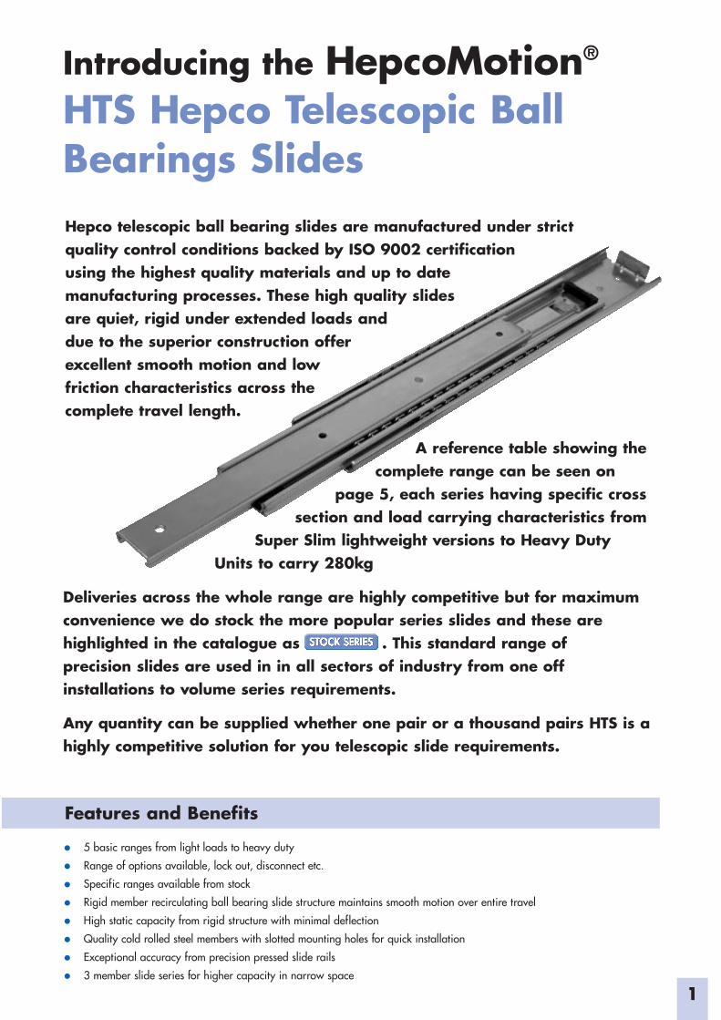
HTS Hepco Telescopic BallBearings SlidesHepco telescopic ball bearing slides are manufactured under strictquality control conditions backed by ISO 9002 certificationusing the highest quality materials and up to datemanufacturing processes. These high quality slidesare quiet, rigid under extended loads anddue to the superior construction offerexcellent smooth motion and lowfriction characteristics across thecomplete travel length.
Features and Benefits
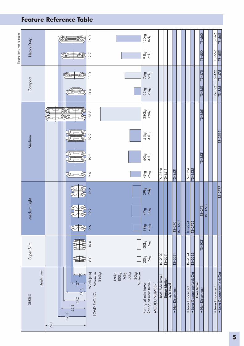
A reference table showing thecomplete range can be seen on
page 5, each series having specific crosssection and load carrying characteristics from
Super Slim lightweight versions to Heavy DutyUnits to carry 280kg
Deliveries across the whole range are highly competitive but for maximumconvenience we do stock the more popular series slides and these arehighlighted in the catalogue as . This standard range ofprecision slides are used in in all sectors of industry from one offinstallations to volume series requirements.
Any quantity can be supplied whether one pair or a thousand pairs HTS is ahighly competitive solution for you telescopic slide requirements.
• 5 basic ranges from light loads to heavy duty
• Range of options available, lock out, disconnect etc.
• Specific ranges available from stock
• Rigid member recirculating ball bearing slide structure maintains smooth motion over entire travel
• High static capacity from rigid structure with minimal deflection
• Quality cold rolled steel members with slotted mounting holes for quick installation
• Exceptional accuracy from precision pressed slide rails
• 3 member slide series for higher capacity in narrow space
2
Construction
Explanation of terms
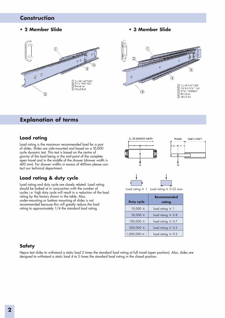
• 2 Member Slide • 3 Member Slide
Load ratingLoad rating is the maximum recommended load for a pairof slides. Slides are side-mounted and based on a 10,000cycle dynamic test. This test is based on the centre ofgravity of the load being in the mid-point of the completeopen travel and in the middle of the drawer (drawer width is400 mm). For drawer widths in excess of 400mm please con-tact our technical department.
Load rating & duty cycleLoad rating and duty cycle are closely related. Load ratingshould be looked at in conjunction with the number ofcycles i.e. high duty cycle will result in a reduction of the loadrating by the factors shown in the table. Also,under-mounting or bottom mounting of slides is notrecommended because this will greatly reduce the loadrating to approximately 1/4 the standard load rating.
SafetyHepco test slides to withstand a static load 2 times the standard load rating at full travel (open position). Also, slides aredesigned to withstand a static load 4 to 5 times the standard load rating in the closed position.
Duty cycleRecommended�
rating
10,000 5 load rating 5 1
50,000 5 load rating 5 0.8
100,000 5 load rating 5 0.7
500,000 5 load rating 5 0.5
1,000,000 5 load rating 5 0.2
Load rating 5 1 Load rating 5 0.25 max
3
Explanation of terms cont.
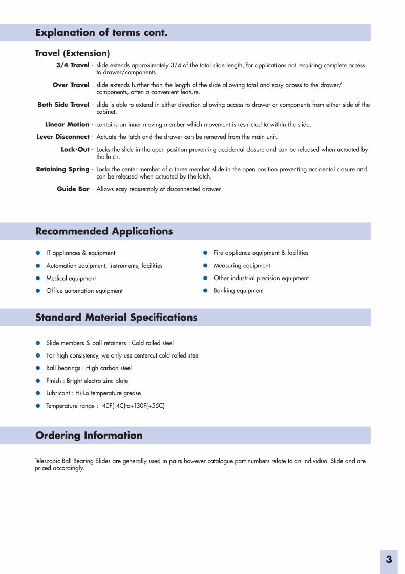
Travel (Extension)3/4 Travel - slide extends approximately 3/4 of the total slide length, for applications not requiring complete access
to drawer/components.
Over Travel - slide extends further than the length of the slide allowing total and easy access to the drawer/components, often a convenient feature.
Both Side Travel - slide is able to extend in either direction allowing access to drawer or components from either side of thecabinet.
Linear Motion - contains an inner moving member which movement is restricted to within the slide.
Lever Disconnect - Actuate the latch and the drawer can be removed from the main unit.
Lock-Out - Locks the slide in the open position preventing accidental closure and can be released when actuated bythe latch.
Retaining Spring - Locks the center member of a three member slide in the open position preventing accidental closure andcan be released when actuated by the latch.
Guide Bar - Allows easy reassembly of disconnected drawer.
• IT appliances & equipment
• Automation equipment, instruments, facilities
• Medical equipment
• Office automation equipment
• Slide members & ball retainers : Cold rolled steel
• For high consistency, we only use centercut cold rolled steel
• Ball bearings : High carbon steel
• Finish : Bright electro zinc plate
• Lubricant : Hi-Lo temperature grease
• Temperature range : -40F(-4C)to+130F(+55C)
Telescopic Ball Bearing Slides are generally used in pairs however catalogue part numbers relate to an individual Slide and arepriced accordingly.
• Fire appliance equipment & facilities
• Measuring equipment
• Other industrial precision equipment
• Banking equipment
Recommended Applications
Standard Material Specifications
Ordering Information
4
Mounting
Customized Slides
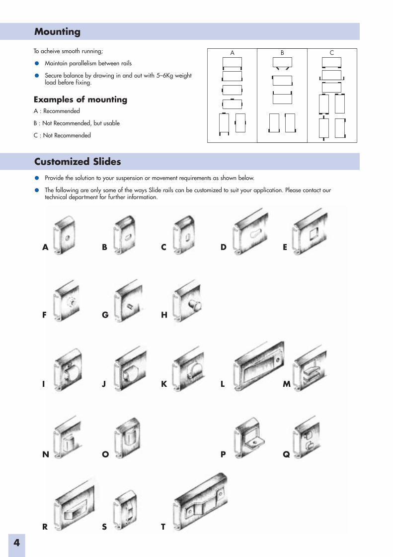
To acheive smooth running;
• Maintain parallelism between rails
• Secure balance by drawing in and out with 5–6Kg weightload before fixing.
Examples of mountingA : Recommended
B : Not Recommended, but usable
C : Not Recommended
• Provide the solution to your suspension or movement requirements as shown below.
• The following are only some of the ways Slide rails can be customized to suit your application. Please contact ourtechnical department for further information.
A B C D E
F G H
I J K L M
N O P Q
R S T
A CB
5
Feature Reference TableSE
RIES
Wid
th(m
m)
LOA
DRA
TIN
GM
axim
um28
0kg
120k
g10
0kg
70kg
50kg
20kg
Min
imum
8.0
16.0
9.6
19.2
19.2
9.6
19.2
19.2
23.8
13.0
13.0
12.7
16.0
20kg
15kg
Ratin
gat
min
trave
lRa
ting
atm
axtra
vel
20kg
15kg
49kg
25kg
60kg
45kg
54kg
41kg
280k
g19
0kg
94kg
72kg
120k
g87
kg
Supe
rSlim
Med
ium
Light
Med
ium
Com
pact
Hea
vyD
uty
Illus
tratio
nsno
tto
scal
e
Hei
ght(
mm
)
74.1
56.3
55.3
47.2
35.3
2720
33kg
23kg
76kg
52kg
38kg
20kg
47kg
31kg
39kg
26kg
MO
DEL/
NU
MBE
RBo
thSi
deTr
avel
Line
arM
otio
n3/
4tr
avel
•N
on-D
iscon
nect
•Le
verD
iscon
nect
•Le
verD
iscon
nect
/Loc
k-O
utO
ver
trav
el•
Non
-Disc
onne
ct
•Le
verD
iscon
nect
•Le
verD
iscon
nect
/Loc
k-O
ut
TS–2
020
TS–2
011
TS–2
021
TS–2
024
TS–2
025
TS–2
031
TS–2
70TS
–U27
0
TS–2
724
TS–2
725
TS–2
73TS
–U27
3
TS–2
737
TS–3
520
TS–3
511
TS–3
521
TS–3
524
TS–3
525
TS–3
531
TS–3
535
TS–3
561
TS–3
50
TS–3
52TS
–355
TS–4
70
TS–4
72TS
–475
TS–5
50
TS–5
52TS
–555
TS–5
60
TS–5
62TS
–565
6
SUPER SLIM
Outer member
Inner member 1.4Ø3.2
60.0
100.0
15.0
20.0
100.0
2–M3 PEM nut
A
B
C
Slide length
Ø3.2X3.8 slot
Travel length
D
20.0
8.0
12.3
20.0
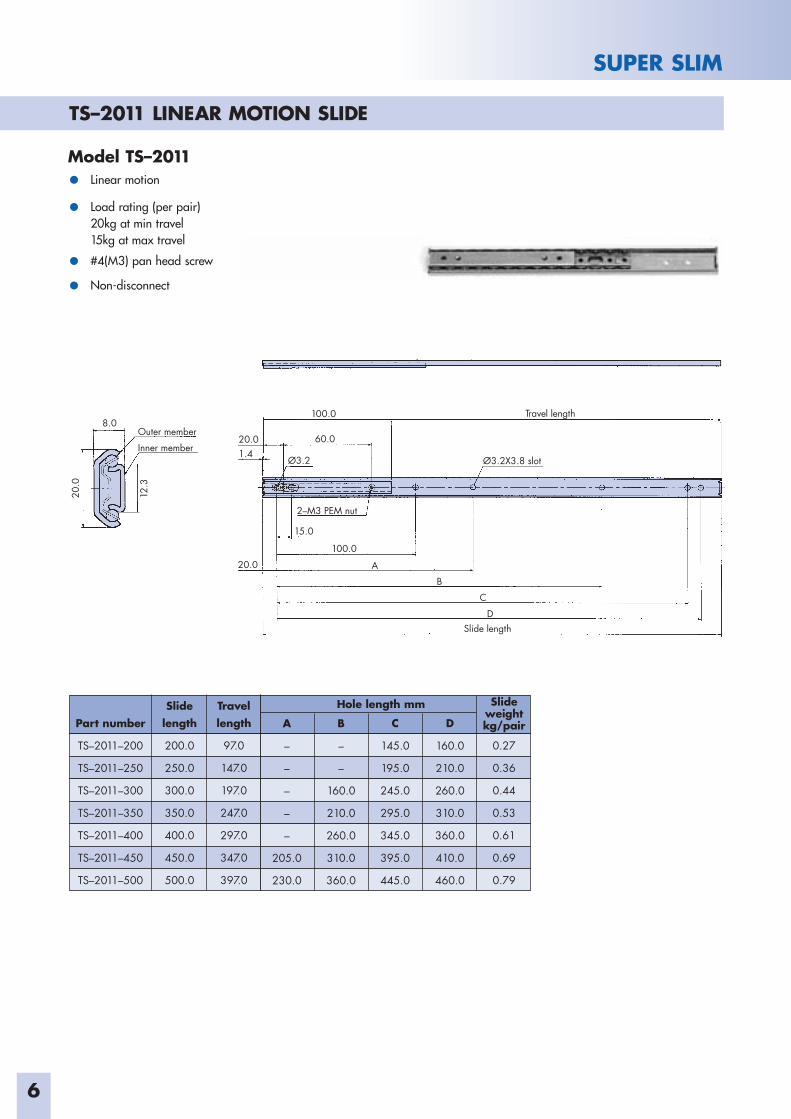
Model TS–2011• Linear motion
• Load rating (per pair)20kg at min travel15kg at max travel
• #4(M3) pan head screw
• Non-disconnect
Part number
TS–2011–200
TS–2011–250
TS–2011–300
TS–2011–350
TS–2011–400
TS–2011–450
TS–2011–500
Slidelength
200.0
250.0
300.0
350.0
400.0
450.0
500.0
Travel length
97.0
147.0
197.0
247.0
297.0
347.0
397.0
Slideweight kg/pair
0.27
0.36
0.44
0.53
0.61
0.69
0.79
A
–
–
–
–
–
205.0
230.0
C
145.0
195.0
245.0
295.0
345.0
395.0
445.0
B
–
–
160.0
210.0
260.0
310.0
360.0
Hole length mm
D
160.0
210.0
260.0
310.0
360.0
410.0
460.0
TS–2011 LINEAR MOTION SLIDE
7
SUPER SLIM
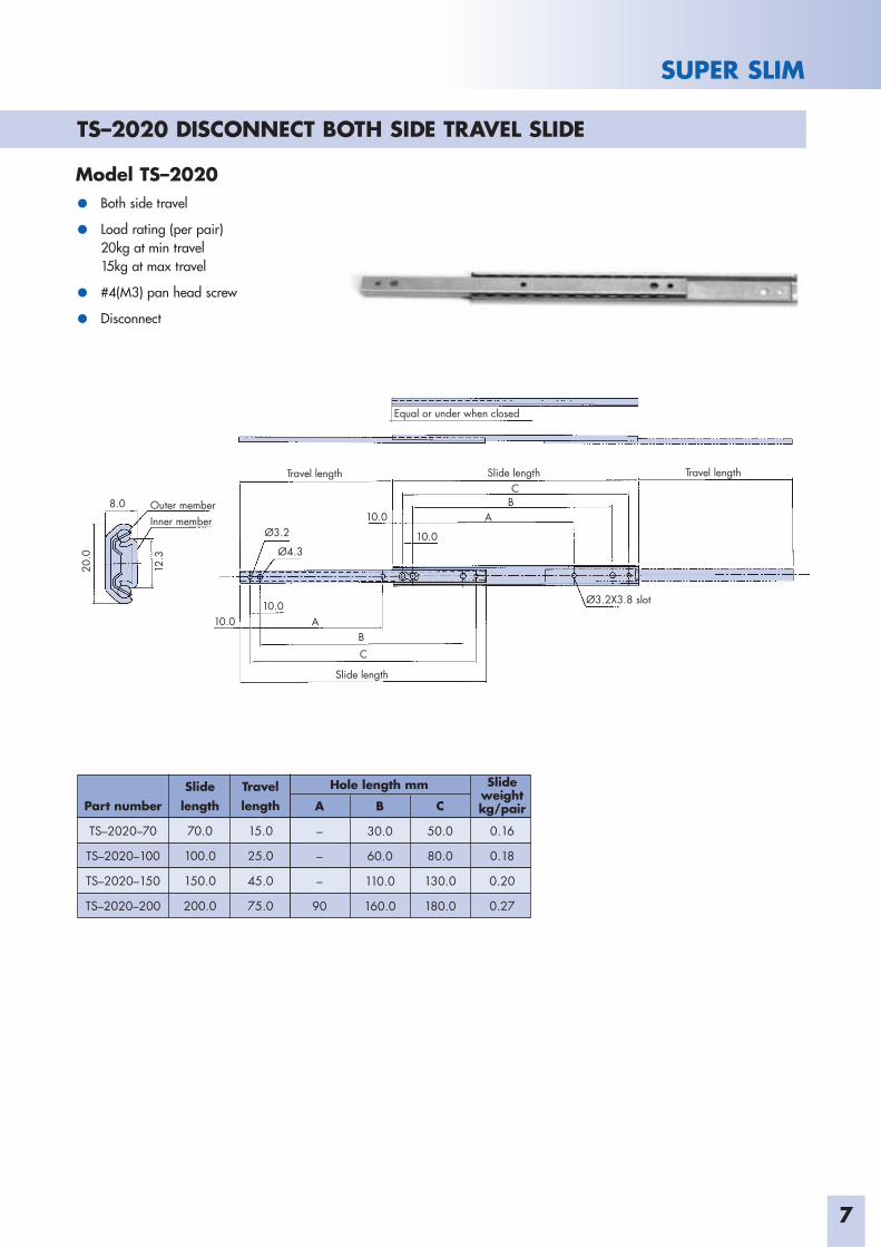
Model TS–2020
• Both side travel
• Load rating (per pair)20kg at min travel15kg at max travel
• #4(M3) pan head screw
• Disconnect
Outer memberInner member
Slide length
Ø3.2X3.8 slot
Travel length Slide length Travel length
Equal or under when closed
8.0
12.3
Ø3.2
Ø4.3
10.0
10.010.0 A
ABC
BC
10.0
20.0
Part number
TS–2020–70
TS–2020–100
TS–2020–150
TS–2020–200
Slidelength
70.0
100.0
150.0
200.0
Travel length
15.0
25.0
45.0
75.0
A
–
–
–
90
C
50.0
80.0
130.0
180.0
B
30.0
60.0
110.0
160.0
Hole length mm Slideweight kg/pair
0.16
0.18
0.20
0.27
TS–2020 DISCONNECT BOTH SIDE TRAVEL SLIDE
8
SUPER SLIM
Outer member Inner member
Slide length -3.0
Ø3.2X3.8 slot Ø3.2X3.8 slot Ø3.2
Slide lengthTravel length
Equal or under when closed
8.0
12.3
12.3
Ø3.2
20.0
Access hole
Access hole
55.0
15.0 100.0
20.0
15.0
55.0100.0
E
AB
CD
FG
20.0
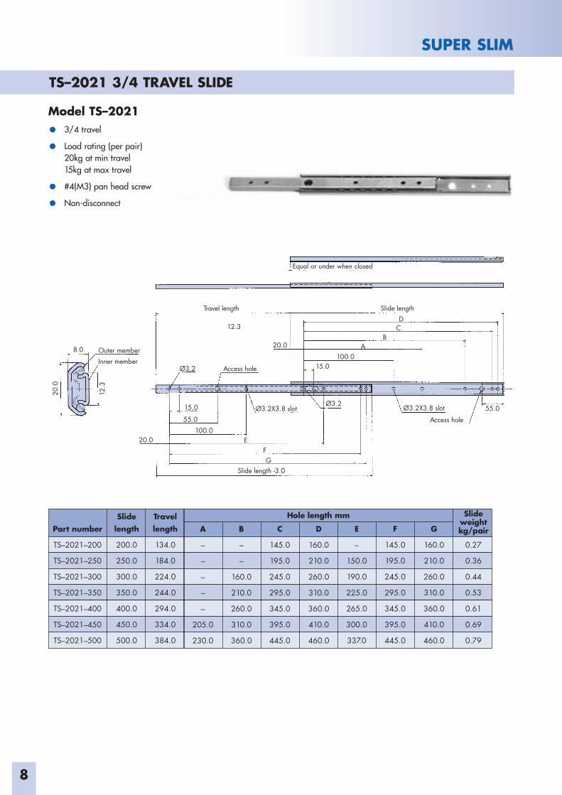
TS–2021 3/4 TRAVEL SLIDE
Model TS–2021
• 3/4 travel
• Load rating (per pair)20kg at min travel15kg at max travel
• #4(M3) pan head screw
• Non-disconnect
Part number
TS–2021–200
TS–2021–250
TS–2021–300
TS–2021–350
TS–2021–400
TS–2021–450
TS–2021–500
Slidelength
200.0
250.0
300.0
350.0
400.0
450.0
500.0
Travel length
134.0
184.0
224.0
244.0
294.0
334.0
384.0
A
–
–
–
–
–
205.0
230.0
C
145.0
195.0
245.0
295.0
345.0
395.0
445.0
B
–
–
160.0
210.0
260.0
310.0
360.0
Hole length mm
D
160.0
210.0
260.0
310.0
360.0
410.0
460.0
F
145.0
195.0
245.0
295.0
345.0
395.0
445.0
E
–
150.0
190.0
225.0
265.0
300.0
337.0
G
160.0
210.0
260.0
310.0
360.0
410.0
460.0
Slideweight kg/pair
0.27
0.36
0.44
0.53
0.61
0.69
0.79
9
SUPER SLIM
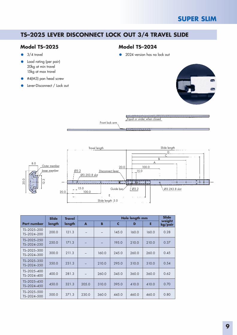
Model TS–2025 Model TS–2024
• 3/4 travel • 2024 version has no lock out
• Load rating (per pair)20kg at min travel15kg at max travel
• #4(M3) pan head screw
• Lever-Disconnect / Lock out
Outer memberInner member
Slide length -3.0
Ø3.2X3.8 slot
Ø3.2X3.8 slot
Travel length Slide length
Equal or under when closed Front lock arm
8.0
12.3
15.0 100.0
100.0
Ø3.2
Ø3.2Guide bar
20.0
20.0 15.0
Disconnect lever
AB
CD
E
20.0
Part number
TS–2025–200TS–2024–200
TS–2025–250TS–2024–250
TS–2025–300TS–2024–300
TS–2025–350TS–2024–350
TS–2025–400TS–2024–400
TS–2025–450TS–2024–450
TS–2025–500TS–2024–500
Slidelength
200.0
250.0
300.0
350.0
400.0
450.0
500.0
Travel length
121.3
171.3
211.3
231.3
281.3
321.3
371.3
A
–
–
–
–
–
205.0
230.0
C
145.0
195.0
245.0
295.0
345.0
395.0
445.0
B
–
–
160.0
210.0
260.0
310.0
360.0
Hole length mm
D
160.0
210.0
260.0
310.0
360.0
410.0
460.0
E
160.0
210.0
260.0
310.0
360.0
410.0
460.0
Slideweight kg/pair
0.28
0.37
0.45
0.54
0.62
0.70
0.80
TS–2025 LEVER DISCONNECT LOCK OUT 3/4 TRAVEL SLIDE
10
SUPER SLIM
Part number
TS–2031–200
TS–2031–250
TS–2031–300
TS–2031–350
TS–2031–400
TS–2031–450
TS–2031–500
Slidelength
200.0
250.0
300.0
350.0
400.0
450.0
500.0
Travel length
229.0
269.0
329.0
369.0
429.0
469.0
529.0
A
–
–
–
–
–
205.0
230.0
C
145.0
195.0
245.0
295.0
345.0
395.0
445.0
B
–
–
160.0
210.0
260.0
310.0
360.0
Hole length mm
D
160.0
210.0
260.0
310.0
360.0
410.0
460.0
Slideweight kg/pair
0.60
0.70
0.93
1.10
1.26
1.43
1.60
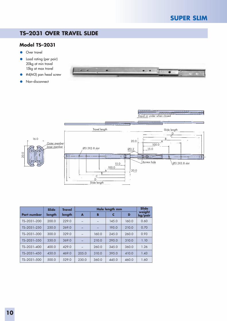
Outer memberInner member
Slide length
Ø3.2X3.8 slot
Ø3.2X3.8 slot
Travel length Slide length
Equal or under when closed
16.0
Ø3.2
15.0
15.0
20.0
Access hole
100.020.0A
AB
CD
BC
D
100.0
20.0
TS–2031 OVER TRAVEL SLIDE
Model TS–2031
• Over travel
• Load rating (per pair)20kg at min travel15kg at max travel
• #4(M3) pan head screw
• Non-disconnect
11
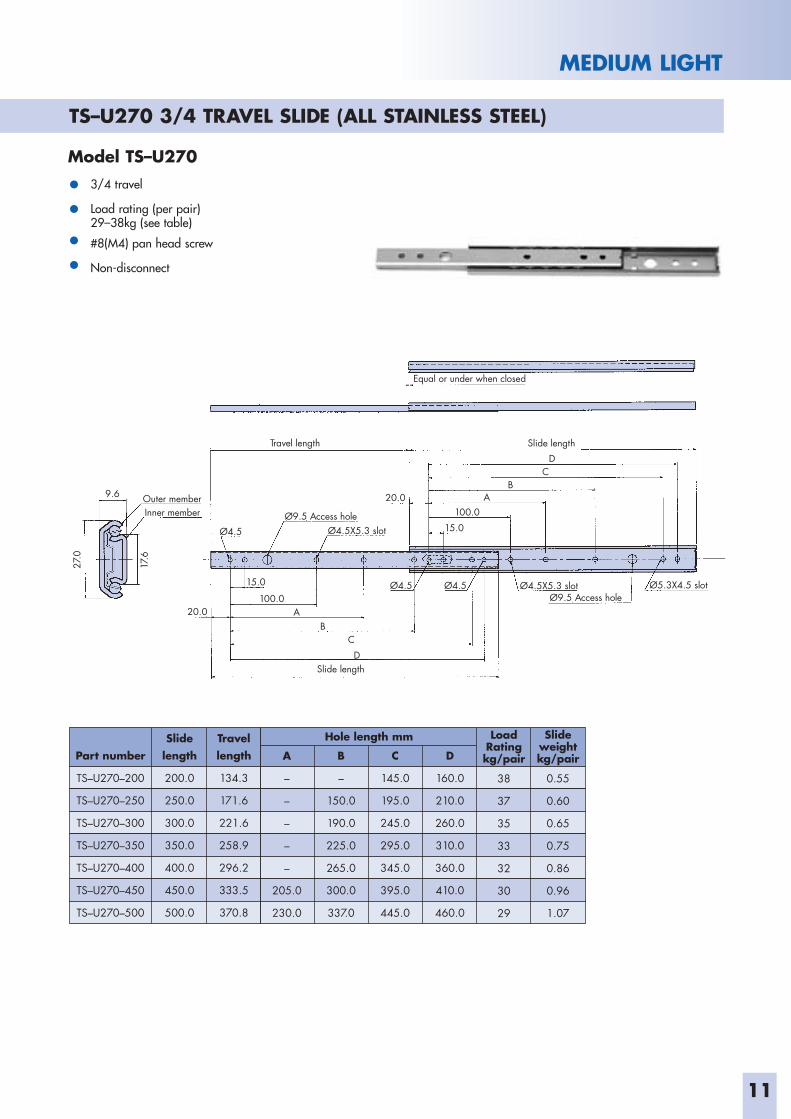
MEDIUM LIGHT
Model TS–U270
• 3/4 travel
• Load rating (per pair)29–38kg (see table)
• #8(M4) pan head screw
• Non-disconnect
Outer memberInner member
Ø4.5X5.3 slot
Ø4.5X5.3 slotØ4.5Ø4.5
Ø9.5 Access hole
Ø9.5 Access holeØ5.3X4.5 slot
Travel length
Slide length
Slide length
Equal or under when closed
Ø4.5 15.0100.0
20.09.6
A
CB
A
D
BC
D
100.0
15.0
20.0
27.0
17.6
Part number
TS–U270–200
TS–U270–250
TS–U270–300
TS–U270–350
TS–U270–400
TS–U270–450
TS–U270–500
Slidelength
200.0
250.0
300.0
350.0
400.0
450.0
500.0
Travel length
134.3
171.6
221.6
258.9
296.2
333.5
370.8
Slideweight kg/pair
0.55
0.60
0.65
0.75
0.86
0.96
1.07
A
–
–
–
–
–
205.0
230.0
C
145.0
195.0
245.0
295.0
345.0
395.0
445.0
B
–
150.0
190.0
225.0
265.0
300.0
337.0
Hole length mm
D
160.0
210.0
260.0
310.0
360.0
410.0
460.0
LoadRating kg/pair
38
37
35
33
32
30
29
TS–U270 3/4 TRAVEL SLIDE (ALL STAINLESS STEEL)
12
MEDIUM LIGHT
Part number
TS–U273–200
TS–U273–250
TS–U273–300
TS–U273–350
TS–U273–400
TS–U273–450
TS–U273–500
Slidelength
200.0
250.0
300.0
350.0
400.0
450.0
500.0
Travel length
217.8
267.0
316.2
365.4
414.6
463.8
513.0
Slideweight kg/pair
0.8
1.0
1.2
1.4
1.5
1.7
1.9
A
–
–
–
–
–
205.0
230.0
C
145.0
195.0
245.0
295.0
345.0
395.0
445.0
B
–
150.0
190.0
225.0
265.0
300.0
337.0
Hole length mm
D
160.0
210.0
260.0
310.0
360.0
410.0
460.0
LoadRating kg/pair
47
46
44
42
40
37
35
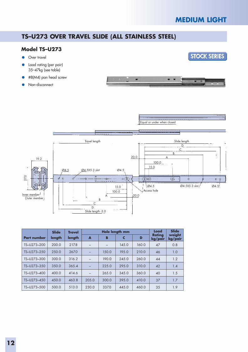
Outer memberInner member
Ø4.5X5.3 slot
Ø4.5X5.3 slotØ4.5 Ø4.5
Ø4.5
Access hole
Travel length
Slide length -3.0
Slide length
Equal or under when closed
Ø4.5 15.0
100.0
20.0
20.0
19.2
A
CB
A
D
BC
D
100.015.0
27.0
TS–U273 OVER TRAVEL SLIDE (ALL STAINLESS STEEL)
Model TS–U273
• Over travel
• Load rating (per pair)35–47kg (see table)
• #8(M4) pan head screw
• Non-disconnect
13
MEDIUM LIGHT
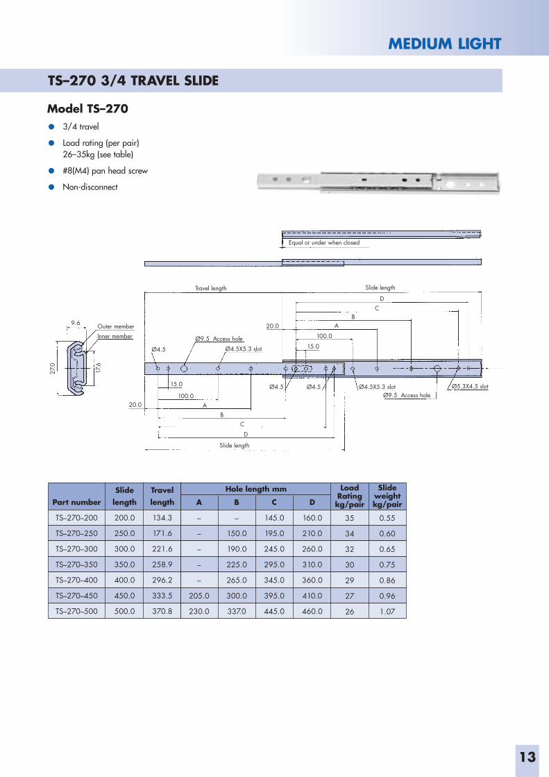
Model TS–270
• 3/4 travel
• Load rating (per pair)26–35kg (see table)
• #8(M4) pan head screw
• Non-disconnect
Outer memberInner member
Slide length
Travel length Slide length
Equal or under when closed
9.6
17.6
Ø4.5
Ø4.5 Ø4.5
Ø9.5 Access hole
Ø9.5 Access hole
Ø4.5X5.3 slot
Ø4.5X5.3 slot Ø5.3X4.5 slot
20.0
100.020.0
15.0
A
AB
CD
BC
D
15.0
100.0
27.0
Part number
TS–270–200
TS–270–250
TS–270–300
TS–270–350
TS–270–400
TS–270–450
TS–270–500
Slidelength
200.0
250.0
300.0
350.0
400.0
450.0
500.0
Travel length
134.3
171.6
221.6
258.9
296.2
333.5
370.8
Slideweight kg/pair
0.55
0.60
0.65
0.75
0.86
0.96
1.07
A
–
–
–
–
–
205.0
230.0
C
145.0
195.0
245.0
295.0
345.0
395.0
445.0
B
–
150.0
190.0
225.0
265.0
300.0
337.0
Hole length mm
D
160.0
210.0
260.0
310.0
360.0
410.0
460.0
LoadRating kg/pair
35
34
32
30
29
27
26
TS–270 3/4 TRAVEL SLIDE
14
MEDIUM LIGHT
Outer memberInner member
Slide length -4.5
Ø4.5X3.3 slot
Ø4.5X5.3 slot
Disconnect lever Guide bar 5.3X4.5
Ø9.5 Access hole Lock out spring
Ø5.3X4.5 slot
Travel length
Lock lever
Slide length
Equal or under when closed
9.6
17.6
15.9
101.625.4 A
EF
DC
111.1 25.4
12.7
15.9
B
27.0
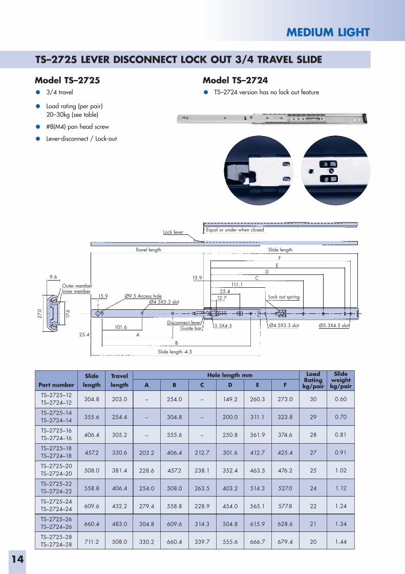
TS–2725 LEVER DISCONNECT LOCK OUT 3/4 TRAVEL SLIDE
Model TS–2725 Model TS–2724• 3/4 travel • TS–2724 version has no lock out feature
• Load rating (per pair)20–30kg (see table)
• #8(M4) pan head screw
• Lever-disconnect / Lock-out
Part number
TS–2725–12 TS–2724–12
TS–2725–14 TS–2724–14
TS–2725–16 TS–2724–16
TS–2725–18 TS–2724–18
TS–2725–20TS–2724–20
TS–2725–22TS–2724–22
TS–2725–24TS–2724–24
TS–2725–26 TS–2724–26
TS–2725–28TS–2724–28
Slidelength
304.8
355.6
406.4
457.2
508.0
558.8
609.6
660.4
711.2
Travel length
203.0
254.4
305.2
330.6
381.4
406.4
432.2
483.0
508.0
A
–
–
–
203.2
228.6
254.0
279.4
304.8
330.2
C
–
–
–
212.7
238.1
263.5
228.9
314.3
339.7
B
254.0
304.8
355.6
406.4
457.2
508.0
558.8
609.6
660.4
Hole length mm
D
149.2
200.0
250.8
301.6
352.4
403.2
454.0
504.8
555.6
F
273.0
323.8
374.6
425.4
476.2
527.0
577.8
628.6
679.4
E
260.3
311.1
361.9
412.7
463.5
514.3
565.1
615.9
666.7
Slideweight kg/pair
0.60
0.70
0.81
0.91
1.02
1.12
1.24
1.34
1.44
LoadRating kg/pair
30
29
28
27
25
24
22
21
20
15
MEDIUM LIGHT
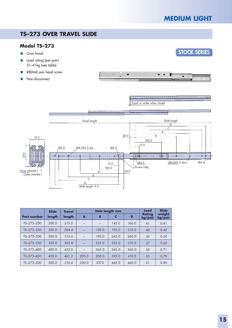
TS–273 OVER TRAVEL SLIDE
Model TS–273
• Over travel
• Load rating (per pair)31–41kg (see table)
• #8(M4) pan head screw
• Non-disconnect
Outer memberInner member
Slide length -3.0
Ø4.5X5.3 slotØ4.5 Access hole
Ø4.5
Travel length Slide length
Equal or under when closed
19.2
15.0 100.0
Ø4.5 Ø4.5X5.3 slot Ø4.5
20.0
15.0 100.0
A
AB
CD
BC
D
20.0
27.0
Part number
TS–273–200
TS–273–250
TS–273–300
TS–273–350
TS–273–400
TS–273–450
TS–273–500
Slidelength
200.0
250.0
300.0
350.0
400.0
450.0
500.0
Travel length
215.0
264.4
313.6
362.8
412.0
461.2
510.4
Slideweight kg/pair
0.41
0.45
0.50
0.60
0.71
0.79
0.90
A
–
–
–
–
–
205.0
230.0
C
145.0
195.0
245.0
295.0
345.0
395.0
445.0
B
–
150.0
190.0
225.0
265.0
300.0
337.0
Hole length mm
D
160.0
210.0
260.0
310.0
360.0
410.0
460.0
LoadRating kg/pair
41
40
39
37
35
33
31
16
MEDIUM LIGHT
Outer memberInner member
Lock out lever
Lock lever
Bumper Ø4.5X5.3 slotØ5.3X4.5 slot
Ø5.3X4.5 slot
Access hole
Travel length Slide length
Slide length -4.5
Equal or under when closed
Ø4.5X5.3 slot Disconnect lever
Retaining spring
Guide bar
15.9
A
FD
E
BCD
E
111.1 25.4 12.7
27.0
17.6
19.2
15.9
12.7 123.8
Part number
TS–2737–12
TS–2737–14
TS–2737–16
TS–2737–18
TS–2737–20
TS–2737–22
TS–2737–24
TS–2737–26
TS–2737–28
Slidelength
304.8
355.6
406.4
457.2
508.0
558.8
609.6
660.4
711.2
Travel length
327.0
378.0
429.0
480.0
530.0
581.0
632.0
683.0
734.0
A
–
–
–
212.7
238.1
263.5
228.9
314.3
339.7
C
–
298.4
349.2
400.0
450.8
501.6
552.4
603.2
654.0
B
–
–
–
–
365.1
415.9
466.7
517.5
568.3
Hole length mm
D
260.3
311.1
361.9
412.7
463.5
514.3
565.1
615.9
666.7
F
–
–
250.8
301.6
352.4
403.2
454.0
504.8
555.6
E
273.0
323.8
374.6
425.4
476.2
527.0
577.8
628.6
679.4
Slideweight kg/pair
0.52
0.62
0.73
0.81
0.92
1.10
1.24
1.34
1.45
LoadRating kg/pair
39
37
35
33
31
29
28
27
26
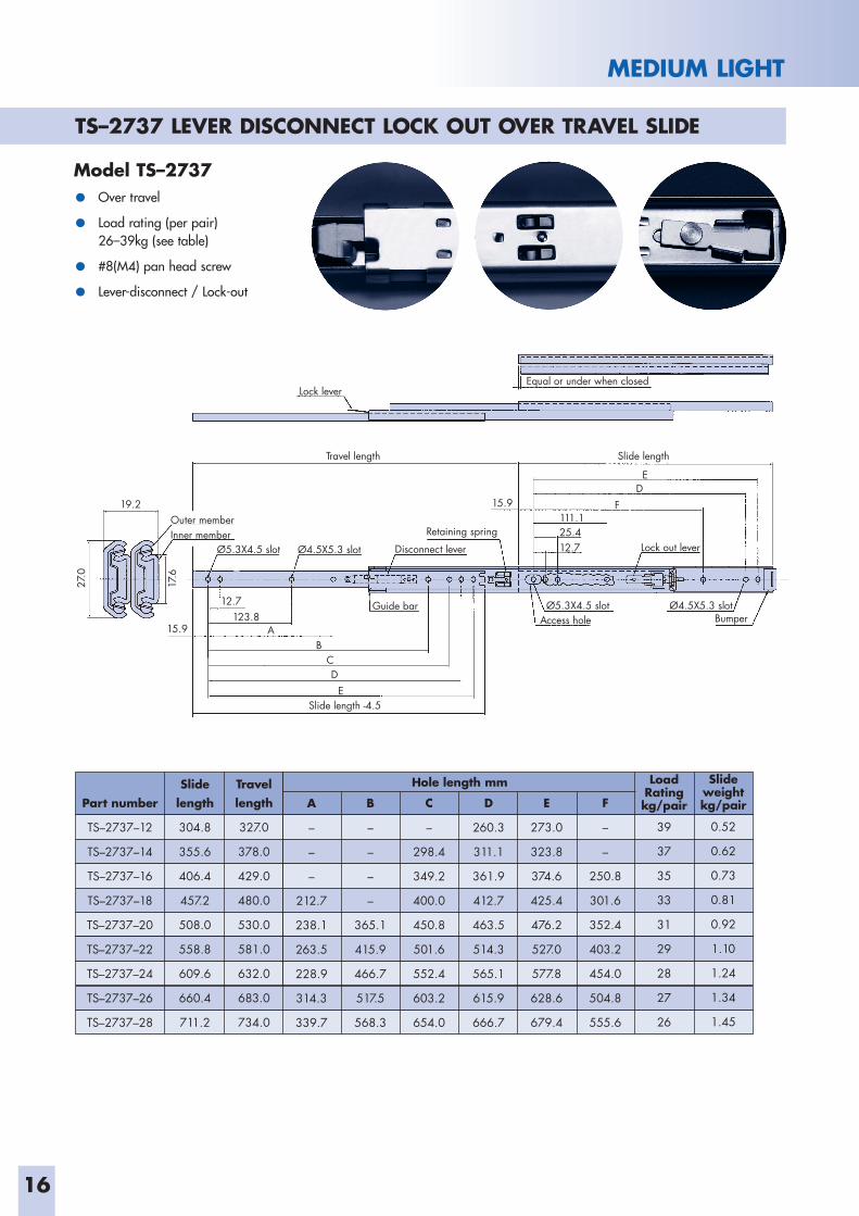
TS–2737 LEVER DISCONNECT LOCK OUT OVER TRAVEL SLIDE
Model TS–2737
• Over travel
• Load rating (per pair)26–39kg (see table)
• #8(M4) pan head screw
• Lever-disconnect / Lock-out
17
MEDIUM
Outer memberInner member
Mounting plate
Ø4.5
Ø4.5X5.3 slot
Slide length
Travel length
9.6 1.6
1.6
8.0
60.4
47.6
101.6
25.4
A
E
D
C
B
35.5
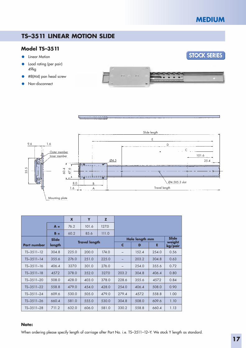
TS–3511 LINEAR MOTION SLIDE
Model TS–3511
• Linear Motion
• Load rating (per pair)49kg
• #8(M4) pan head screw
• Non-disconnect
Part number
TS–3511–12
TS–3511–14
TS–3511–16
TS–3511–18
TS–3511–20
TS–3511–22
TS–3511–24
TS–3511–26
TS–3511–28
Slidelength
304.8
355.6
406.4
457.2
508.0
558.8
609.6
660.4
711.2
225.0
276.0
327.0
378.0
428.0
479.0
530.0
581.0
632.0
200.0
251.0
301.0
352.0
403.0
454.0
505.0
555.0
606.0
C
–
–
–
203.2
228.6
254.0
279.4
304.8
330.2
174.0
225.0
276.0
327.0
378.0
428.0
479.0
530.0
581.0
Hole length mm
D
152.4
203.2
254.0
304.8
355.6
406.4
457.2
508.0
558.8
kg/pair
0.56
0.63
0.72
0.80
0.84
0.90
1.00
1.10
1.13
E
254.0
304.8
355.6
406.4
457.2
508.0
558.8
609.6
660.4
Travel lengthSlide
weight
A = 76.2 101.6 127.0
B = 60.2 85.6 111.0
X Y Z
Note:
When ordering please specify length of carriage after Part No. i.e. TS–3511–12–Y. We stock Y length as standard.
18
MEDIUM
Outer memberInner member
Ø4.5X5.3 slot
Ø4.5X5.3 slot
Ø5.3X4.5 slot
Ø5.3X4.5 slot
Ø5.3X4.5 slot
Travel length (front)
Slide length
Slide length (rear)
Equal or under when closed
9.6
Ø9.5
15.9111.125.412.7
15.925.4
A
FE
D
G
BC
101.6
35.5
24.2
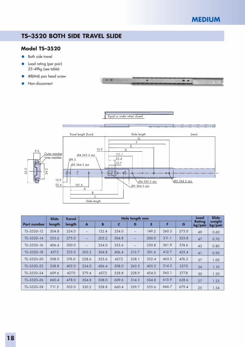
TS–3520 BOTH SIDE TRAVEL SLIDE
Model TS–3520
• Both side travel
• Load rating (per pair)25–49kg (see table)
• #8(M4) pan head screw
• Non-disconnect
Part number
TS–3520–12
TS–3520–14
TS–3520–16
TS–3520–18
TS–3520–20
TS–3520–22
TS–3520–24
TS–3520–26
TS–3520–28
Slidelength
304.8
355.6
406.4
457.2
508.0
558.8
609.6
660.4
711.2
Travel length
224.0
275.0
300.0
325.0
376.0
402.0
427.0
478.0
503.0
A
–
–
–
203.2
228.6
254.0
279.4
304.8
330.2
C
254.0
304.8
355.6
406.4
457.2
508.0
558.8
609.6
660.4
B
152.4
203.2
254.0
304.8
355.6
406.4
457.2
508.0
558.8
Hole length mm
D
–
–
–
212.7
238.1
263.5
228.9
314.3
339.7
F
260.3
311.1
361.9
412.7
463.5
514.3
565.1
615.9
666.7
E
149.2
200.0
250.8
301.6
352.4
403.2
454.0
504.8
555.6
G
273.0
323.8
374.6
425.4
476.2
527.0
577.8
628.6
679.4
Slideweight kg/pair
0.60
0.70
0.80
0.90
1.00
1.10
1.20
1.25
1.34
LoadRating kg/pair
49
47
43
41
37
34
30
27
25
19
MEDIUM
Outer member Inner member
Ø4.5X5.3 slot
Ø4.5X5.3 slot
Ø5.3X4.5 slot
Ø5.3X4.5 slot
Travel length
Slide length -3.0
Slide length
Equal or under when closed
9.6
Ø9.5
15.9
111.1 25.412.7
Ø5.3X4.5 slot15.9
25.4A
FE
D
G
BC
101.6
35.5
24.2
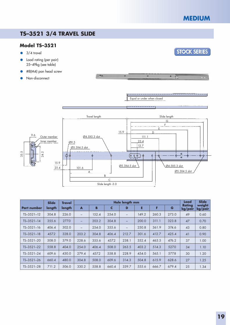
TS–3521 3/4 TRAVEL SLIDE
Model TS–3521
• 3/4 travel
• Load rating (per pair)25–49kg (see table)
• #8(M4) pan head screw
• Non-disconnect
Part number
TS–3521–12
TS–3521–14
TS–3521–16
TS–3521–18
TS–3521–20
TS–3521–22
TS–3521–24
TS–3521–26
TS–3521–28
Slidelength
304.8
355.6
406.4
457.2
508.0
558.8
609.6
660.4
711.2
Travel length
226.0
277.0
302.0
328.0
379.0
404.0
430.0
480.0
506.0
A
–
–
–
203.2
228.6
254.0
279.4
304.8
330.2
C
254.0
304.8
355.6
406.4
457.2
508.0
558.8
609.6
660.4
B
152.4
203.2
254.0
304.8
355.6
406.4
457.2
508.0
558.8
Hole length mm
D
–
–
–
212.7
238.1
263.5
228.9
314.3
339.7
F
260.3
311.1
361.9
412.7
463.5
514.3
565.1
615.9
666.7
E
149.2
200.0
250.8
301.6
352.4
403.2
454.0
504.8
555.6
G
273.0
323.8
374.6
425.4
476.2
527.0
577.8
628.6
679.4
Slideweight kg/pair
0.60
0.70
0.80
0.90
1.00
1.10
1.20
1.25
1.34
LoadRating kg/pair
49
47
43
41
37
34
30
27
25
20
MEDIUM
Outer member Inner member
Ø4.5X5.3 slot
Retaining spring
Ø5.3X4.5 slot
Ø5.3X4.5 slot
Guide bar Disconnect lever Ø5.3X4.5 slot Bumper
Travel length
Slide length -4.5
Slide length
Equal or under when closed Lock lever
9.6
Ø9.5
15.9 111.1
25.4
12.7
15.9
25.4
A
FE
D
G
B
C
101.6
35.5
24.2
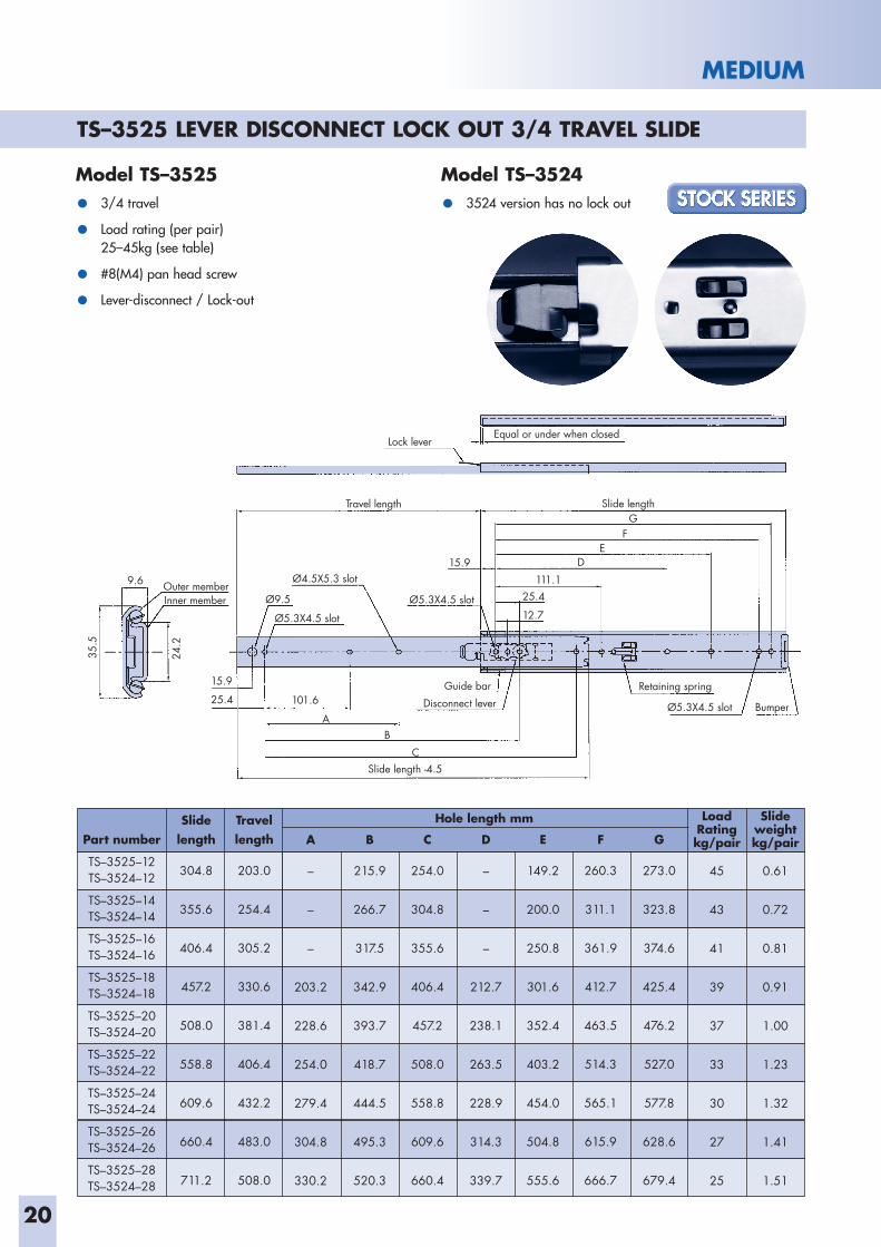
TS–3525 LEVER DISCONNECT LOCK OUT 3/4 TRAVEL SLIDE
Model TS–3525 Model TS–3524
• 3/4 travel • 3524 version has no lock out
• Load rating (per pair)25–45kg (see table)
• #8(M4) pan head screw
• Lever-disconnect / Lock-out
Part number
TS–3525–12 TS–3524–12
TS–3525–14 TS–3524–14
TS–3525–16 TS–3524–16
TS–3525–18 TS–3524–18
TS–3525–20TS–3524–20
TS–3525–22TS–3524–22
TS–3525–24TS–3524–24
TS–3525–26 TS–3524–26
TS–3525–28TS–3524–28
Slidelength
304.8
355.6
406.4
457.2
508.0
558.8
609.6
660.4
711.2
Travel length
203.0
254.4
305.2
330.6
381.4
406.4
432.2
483.0
508.0
A
–
–
–
203.2
228.6
254.0
279.4
304.8
330.2
C
254.0
304.8
355.6
406.4
457.2
508.0
558.8
609.6
660.4
B
215.9
266.7
317.5
342.9
393.7
418.7
444.5
495.3
520.3
Hole length mm
D
–
–
–
212.7
238.1
263.5
228.9
314.3
339.7
F
260.3
311.1
361.9
412.7
463.5
514.3
565.1
615.9
666.7
E
149.2
200.0
250.8
301.6
352.4
403.2
454.0
504.8
555.6
G
273.0
323.8
374.6
425.4
476.2
527.0
577.8
628.6
679.4
Slideweight kg/pair
0.61
0.72
0.81
0.91
1.00
1.23
1.32
1.41
1.51
LoadRating kg/pair
45
43
41
39
37
33
30
27
25
21
MEDIUM
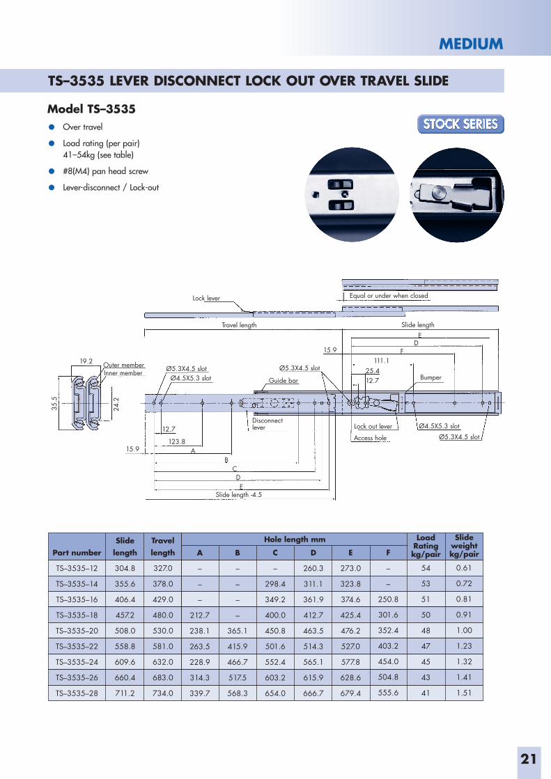
Model TS–3535
• Over travel
• Load rating (per pair)41–54kg (see table)
• #8(M4) pan head screw
• Lever-disconnect / Lock-out
Outer memberInner member
Ø4.5X5.3 slot
Ø4.5X5.3 slot
Ø5.3X4.5 slot Ø5.3X4.5 slot
Lock out lever
Access hole
Disconnect lever
Ø5.3X4.5 slot
Travel length
Lock lever
Slide length -4.5
Slide length
Bumper
Equal or under when closed
19.2
Guide bar
15.9 111.1
25.412.7
12.7
123.8A
DF
E
BCDE
15.9
35.5
24.2
Part number
TS–3535–12
TS–3535–14
TS–3535–16
TS–3535–18
TS–3535–20
TS–3535–22
TS–3535–24
TS–3535–26
TS–3535–28
Slidelength
304.8
355.6
406.4
457.2
508.0
558.8
609.6
660.4
711.2
Travel length
327.0
378.0
429.0
480.0
530.0
581.0
632.0
683.0
734.0
A
–
–
–
212.7
238.1
263.5
228.9
314.3
339.7
C
–
298.4
349.2
400.0
450.8
501.6
552.4
603.2
654.0
B
–
–
–
–
365.1
415.9
466.7
517.5
568.3
Hole length mm
D
260.3
311.1
361.9
412.7
463.5
514.3
565.1
615.9
666.7
F
–
–
250.8
301.6
352.4
403.2
454.0
504.8
555.6
E
273.0
323.8
374.6
425.4
476.2
527.0
577.8
628.6
679.4
Slideweight kg/pair
0.61
0.72
0.81
0.91
1.00
1.23
1.32
1.41
1.51
LoadRating kg/pair
54
53
51
50
48
47
45
43
41
TS–3535 LEVER DISCONNECT LOCK OUT OVER TRAVEL SLIDE
22
MEDIUM
Outer memberInner member Ø4.5X5.3 slot
Ø4.5X5.3 slot
Ø5.3X4.5 slot
Ø5.3X4.5 slot
Access hole Ø5.3X4.5 slot
Travel length
Slide length
Slide length
Equal or under when closed
19.215.9
111.125.412.7
A
CB
A
D
BC
D
12.7
25.4
111.115.9
35.5
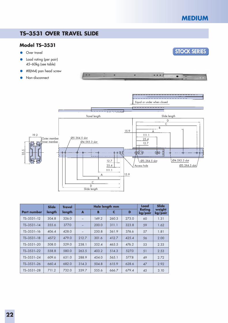
TS–3531 OVER TRAVEL SLIDE
Model TS–3531
• Over travel
• Load rating (per pair)45–60kg (see table)
• #8(M4) pan head screw
• Non-disconnect
Part number
TS–3531–12
TS–3531–14
TS–3531–16
TS–3531–18
TS–3531–20
TS–3531–22
TS–3531–24
TS–3531–26
TS–3531–28
Slidelength
304.8
355.6
406.4
457.2
508.0
558.8
609.6
660.4
711.2
Travel length
326.0
377.0
428.0
479.0
529.0
580.0
631.0
682.0
732.0
Slideweight kg/pair
1.31
1.62
1.81
2.00
2.33
2.53
2.72
2.92
3.10
A
–
–
–
212.7
238.1
263.5
288.9
314.3
339.7
C
260.3
311.1
361.9
412.7
463.5
514.3
565.1
615.9
666.7
B
149.2
200.0
250.8
301.6
352.4
403.2
454.0
504.8
555.6
Hole length mm
D
273.0
323.8
374.6
425.4
476.2
527.0
577.8
628.6
679.4
LoadRating kg/pair
60
59
57
56
53
51
49
47
45
23
MEDIUM
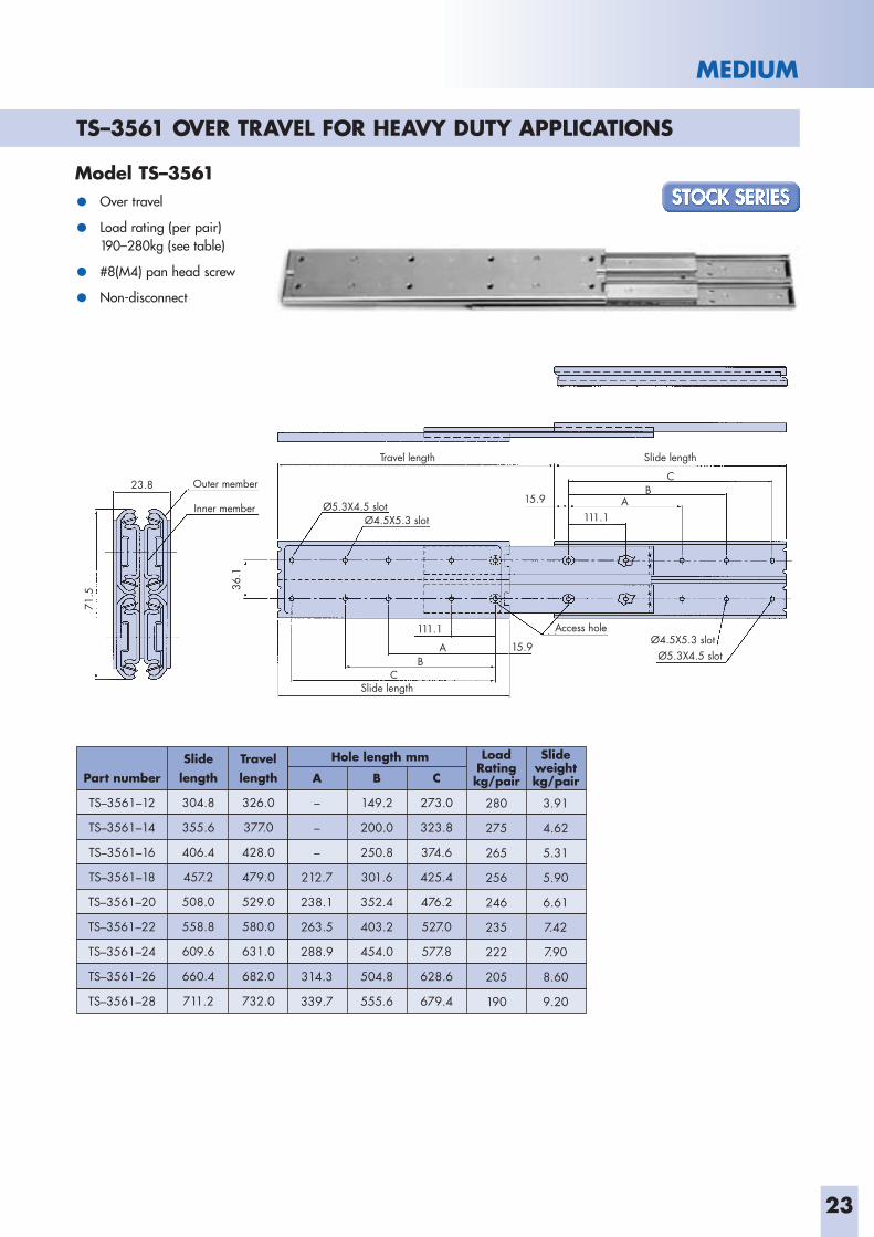
TS–3561 OVER TRAVEL FOR HEAVY DUTY APPLICATIONS
Model TS–3561
• Over travel
• Load rating (per pair)190–280kg (see table)
• #8(M4) pan head screw
• Non-disconnect
Outer member
Inner memberØ4.5X5.3 slot
Ø4.5X5.3 slot
Ø5.3X4.5 slot
Access hole
Ø5.3X4.5 slot
Travel length
Slide length
Slide length
23.815.9
111.1
15.9A
BA
C
BC
111.1
71.5
36.1
Part number
TS–3561–12
TS–3561–14
TS–3561–16
TS–3561–18
TS–3561–20
TS–3561–22
TS–3561–24
TS–3561–26
TS–3561–28
Slidelength
304.8
355.6
406.4
457.2
508.0
558.8
609.6
660.4
711.2
Travel length
326.0
377.0
428.0
479.0
529.0
580.0
631.0
682.0
732.0
A
–
–
–
212.7
238.1
263.5
288.9
314.3
339.7
C
273.0
323.8
374.6
425.4
476.2
527.0
577.8
628.6
679.4
B
149.2
200.0
250.8
301.6
352.4
403.2
454.0
504.8
555.6
Hole length mm Slideweight kg/pair
3.91
4.62
5.31
5.90
6.61
7.42
7.90
8.60
9.20
LoadRating kg/pair
280
275
265
256
246
235
222
205
190
24
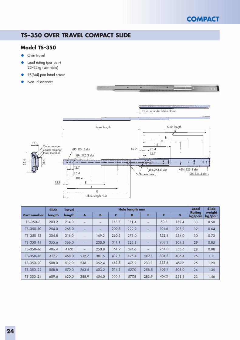
TS–350 OVER TRAVEL COMPACT SLIDE
COMPACT
Model TS–350
• Over travel
• Load rating (per pair)23–33kg (see table)
• #8(M4) pan head screw
• Non- disconnect
Outer member Center member Inner member
Ø4.5X5.3 slot
Ø4.5X5.3 slot
Ø5.3X4.5 slot
Ø5.3X4.5 slotØ5.3X4.5 slot
Access hole
Travel length
Slide length -9.0
Slide length
Equal or under when closed
13.1
15.9 111.1
25.4
12.7
12.7
15.9 E
BA
CD
FG
35.4
25.4
Part number
TS–350–8
TS–350–10
TS–350–12
TS–350–14
TS–350–16
TS–350–18
TS–350–20
TS–350–22
TS–350–24
Slidelength
203.2
254.0
304.8
355.6
406.4
457.2
508.0
558.8
609.6
Travel length
214.0
265.0
316.0
366.0
417.0
468.0
519.0
570.0
620.0
A
–
–
–
–
–
212.7
238.1
263.5
288.9
C
158.7
209.5
260.3
311.1
361.9
412.7
463.5
514.3
565.1
B
–
–
149.2
200.0
250.8
301.6
352.4
403.2
454.0
Hole length mm
D
171.4
222.2
273.0
323.8
374.6
425.4
476.2
527.0
577.8
F
50.8
101.6
152.4
203.2
254.0
304.8
355.6
406.4
457.2
E
–
–
–
–
–
207.7
233.1
258.5
283.9
G
152.4
203.2
254.0
304.8
355.6
406.4
457.2
508.0
558.8
Slideweight kg/pair
0.50
0.64
0.73
0.85
0.98
1.11
1.23
1.35
1.46
LoadRating kg/pair
33
32
30
29
28
26
25
24
23
25
COMPACT
Part number
TS–352–8
TS–352–10
TS–352–12
TS–352–14
TS–352–16
TS–352–18
TS–352–20
TS–352–22
TS–352–24
Slidelength
203.2
254.0
304.8
355.6
406.4
457.2
508.0
558.8
609.6
Travel length
214.0
265.0
316.0
366.0
417.0
468.0
519.0
570.0
620.0
A
–
–
–
–
–
212.7
238.1
263.5
288.9
C
158.7
209.5
260.3
311.1
361.9
412.7
463.5
514.3
565.1
B
–
–
149.2
200.0
250.8
301.6
352.4
403.2
454.0
Hole length mm
D
171.4
222.2
273.0
323.8
374.6
425.4
476.2
527.0
577.8
F
–
–
–
–
–
–
355.6
406.4
457.2
E
–
–
–
–
–
207.7
233.1
258.5
283.9
G
152.4
203.2
254.0
304.8
355.6
406.4
457.2
508.0
558.8
Slideweight kg/pair
0.50
0.64
0.73
0.85
0.98
1.11
1.23
1.35
1.46
LoadRating kg/pair
31
30
29
28
27
26
25
24
23
Outer member Center member Inner member Disconnect lever
Ø4.5X5.3 slotGuide bar Ø5.3X4.5 slot
Access hole Ø5.3X4.5 slot
Travel length
Front lock arm
Slide length -9.0
Slide length
Equal or under when closed
13.1 15.9
111.1 25.4
12.7
15.9
25.412.7
5.3X4.5
4.5X5.3
101.6E
BA
DC
FG
35.4
16.4
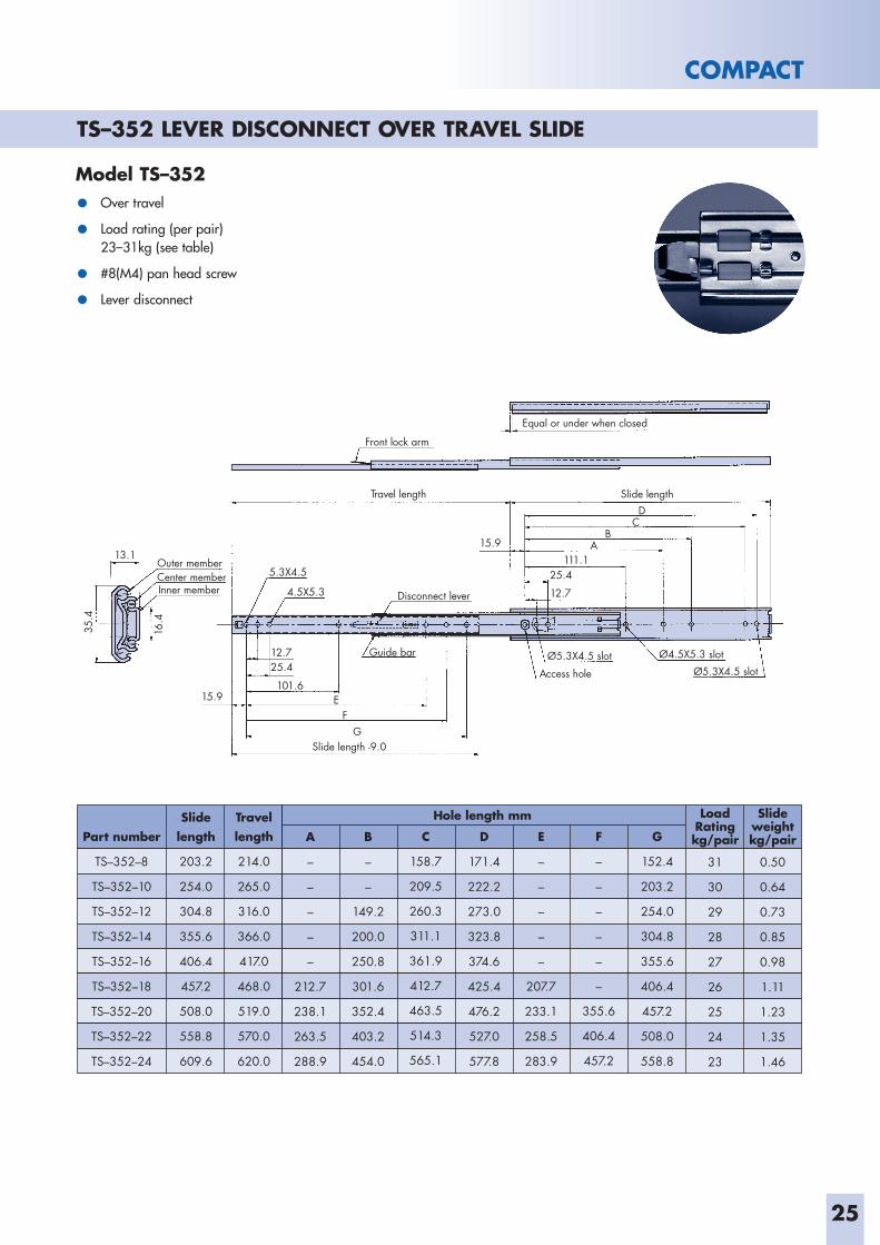
Model TS–352
• Over travel
• Load rating (per pair)23–31kg (see table)
• #8(M4) pan head screw
• Lever disconnect
TS–352 LEVER DISCONNECT OVER TRAVEL SLIDE
26
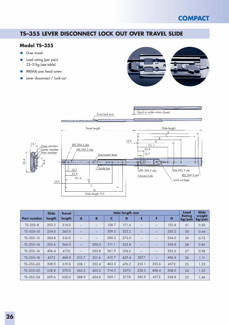
TS–355 LEVER DISCONNECT LOCK OUT OVER TRAVEL SLIDE
COMPACT
Part number
TS–355–8
TS–355–10
TS–355–12
TS–355–14
TS–355–16
TS–355–18
TS–355–20
TS–355–22
TS–355–24
Slidelength
203.2
254.0
304.8
355.6
406.4
457.2
508.0
558.8
609.6
Travel length
214.0
265.0
316.0
366.0
417.0
468.0
519.0
570.0
620.0
A
–
–
–
–
–
212.7
238.1
263.5
288.9
C
158.7
209.5
260.3
311.1
361.9
412.7
463.5
514.3
565.1
B
–
–
–
200.0
250.8
301.6
352.4
403.2
454.0
Hole length mm
D
171.4
222.2
273.0
323.8
374.6
425.4
476.2
527.0
577.8
F
–
–
–
–
–
–
355.6
406.4
457.2
E
–
–
–
–
–
207.7
233.1
258.5
283.9
G
152.4
203.2
254.0
304.8
355.6
406.4
457.2
508.0
558.8
Slideweight kg/pair
0.50
0.64
0.73
0.85
0.98
1.11
1.23
1.35
1.46
LoadRating kg/pair
31
30
29
28
27
26
25
24
23
Outer member Center member Inner member
Disconnect lever
Ø4.5X5.3 slotGuide bar
Ø5.3X4.5 slot
Ø5.3X4.5 slot
Ø4.5X5.3 slot
Access hole Ø5.3X4.5 slot
Lock out lever
Travel length
Front lock arm
Slide length -9.0
Slide length
Equal or under when closed
13.1 15.9
111.1 25.4
12.7
15.9
25.412.7
101.6E
BA
DC
FG
35.4
16.4
Model TS–355
• Over travel
• Load rating (per pair)23–31kg (see table)
• #8(M4) pan head screw
• Lever disconnect / Lock-out
27
COMPACT
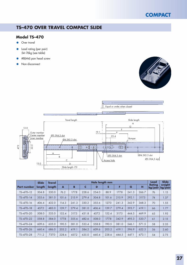
Outer memberCenter memberInner member
Ø4.5X5.3 slot
Ø4.5X5.3 slot
Ø5.3X4.5 slot
Access hole Ø5.3X4.5 slot
Ø5.3X4.5 slot
Travel length
Slide length -7.0
Slide length
Equal or under when closed
13.0
19.1
25.4
13.0
A
FE
HG
Bumper
BC
D
47.2
22.5
Model TS–470• Over travel
• Load rating (per pair)54–76kg (see table)
• #8(M4) pan head screw
• Non-disconnect
Part number
TS–470–12
TS–470–14
TS–470–16
TS–470–18
TS–470–20
TS–470–22
TS–470–24
TS–470–26
TS–470–28
Slidelength
304.8
355.6
406.4
457.2
508.0
558.8
609.6
660.4
711.2
Travel length
330.0
381.0
432.0
483.0
533.0
584.0
635.0
686.0
737.0
A
76.2
101.6
114.3
139.7
152.4
177.8
190.5
203.2
228.6
C
228.6
279.4
330.2
381.0
431.8
482.6
533.4
584.2
635.0
B
177.8
215.9
241.3
279.4
317.5
355.6
381.0
419.1
457.2
Hole length mm
D
254.0
304.8
355.6
406.4
457.2
508.0
558.8
609.6
660.4
F
177.8
215.9
241.3
279.4
317.5
342.9
381.0
419.1
444.5
E
88.9
101.6
127.0
139.7
152.4
177.8
190.5
203.2
228.6
G
241.3
292.1
342.9
393.7
444.5
495.3
546.1
596.9
647.1
H
266.7
317.5
368.3
419.1
469.9
520.7
571.5
622.3
673.1
Slide weight kg/pair
1.15
1.37
1.55
1.77
1.95
2.15
2.35
2.60
2.75
LoadRating kg/pair
76
74
70
66
63
61
58
56
54
TS–470 OVER TRAVEL COMPACT SLIDE
28
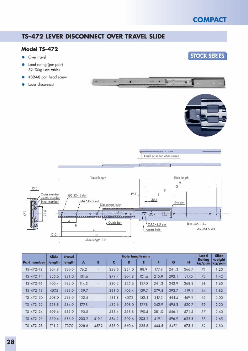
TS–472 LEVER DISCONNECT OVER TRAVEL SLIDE
COMPACT
Model TS–472
• Over travel
• Load rating (per pair)52–74kg (see table)
• #8(M4) pan head screw
• Lever disconnect
Outer memberCenter memberInner member
Ø4.5X5.3 slot
Ø4.5X5.3 slot
Guide bar
Disconnect lever
Ø5.3X4.5 slot
Access hole Ø5.3X4.5 slot
Ø5.3X4.5 slot
Travel length
Slide length -7.0
Slide length
Equal or under when closed
13.0
19.1
25.4
13.0
A
FE
HG
Bumper
BC
D
47.2
22.5
Part number
TS–472–12
TS–472–14
TS–472–16
TS–472–18
TS–472–20
TS–472–22
TS–472–24
TS–472–26
TS–472–28
Slidelength
304.8
355.6
406.4
457.2
508.0
558.8
609.6
660.4
711.2
Travel length
330.0
381.0
432.0
483.0
533.0
584.0
635.0
686.0
737.0
A
76.2
101.6
114.3
139.7
152.4
177.8
190.5
203.2
228.6
C
228.6
279.4
330.2
381.0
431.8
482.6
533.4
584.2
635.0
B
–
–
–
–
–
–
–
419.1
457.2
Hole length mm
D
254.0
304.8
355.6
406.4
457.2
508.0
558.8
609.6
660.4
F
177.8
215.9
241.3
279.4
317.5
342.9
381.0
419.1
444.5
E
88.9
101.6
127.0
139.7
152.4
177.8
190.5
203.2
228.6
G
241.3
292.1
342.9
393.7
444.5
495.3
546.1
596.9
647.1
H
266.7
317.5
368.3
419.1
469.9
520.7
571.5
622.3
673.1
Slide weight kg/pair
1.20
1.42
1.60
1.82
2.00
2.20
2.40
2.65
2.80
LoadRating kg/pair
74
72
68
64
62
59
57
55
52
29
COMPACT
Part number
TS–475–12
TS–475–14
TS–475–16
TS–475–18
TS–475–20
TS–475–22
TS–475–24
TS–475–26
TS–475–28
Slidelength
304.8
355.6
406.4
457.2
508.0
558.8
609.6
660.4
711.2
Travellength
330.0
381.0
432.0
483.0
533.0
584.0
635.0
686.0
737.0
A
76.2
101.6
114.3
139.7
152.4
177.8
190.5
203.2
228.6
C
228.6
279.4
330.2
381.0
431.8
482.6
533.4
584.2
635.0
B
–
–
–
–
–
–
–
419.1
457.2
Hole length mm
D
88.9
101.6
127.0
139.7
152.4
177.8
190.5
203.2
228.6
F
241.3
292.1
342.9
393.7
444.5
495.3
546.1
596.9
647.7
E
177.8
215.9
241.3
279.4
317.5
342.9
381.0
419.1
444.5
G
266.7
317.5
368.3
419.1
469.9
520.7
571.5
622.3
673.1
Slideweightkg/pair
1.20
1.42
1.60
1.82
2.00
2.20
2.40
2.65
2.80
LoadRating
kg/pair
74
72
68
64
62
59
57
55
52
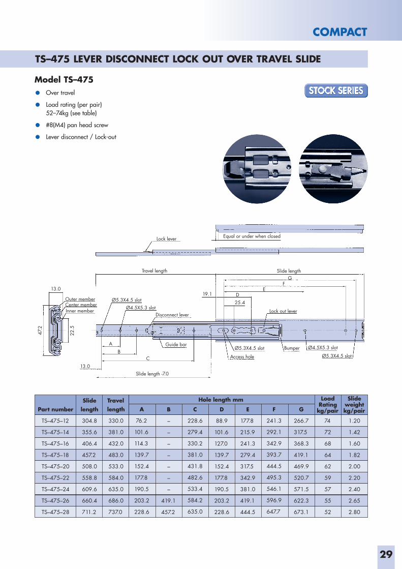
Outer memberCenter member Inner member
Ø4.5X5.3 slot
Ø4.5X5.3 slot
Guide bar
Disconnect lever
Ø5.3X4.5 slot
Access hole Ø5.3X4.5 slot
Ø5.3X4.5 slot
Travel length
Lock lever
Slide length -7.0
Slide length
Equal or under when closed
13.0 19.1
25.4
13.0
A
ED
GF
Lock out lever
BumperB
C
47.2
22.5
Model TS–475
• Over travel
• Load rating (per pair)52–74kg (see table)
• #8(M4) pan head screw
• Lever disconnect / Lock-out
TS–475 LEVER DISCONNECT LOCK OUT OVER TRAVEL SLIDE
30
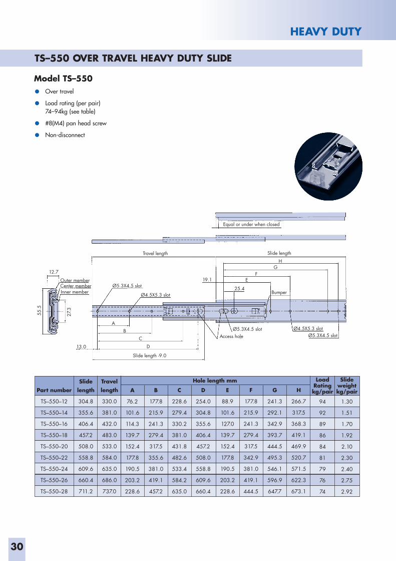
TS–550 OVER TRAVEL HEAVY DUTY SLIDE
HEAVY DUTY
Outer memberCenter member Inner member
Ø4.5X5.3 slot
Ø4.5X5.3 slot
Ø5.3X4.5 slotAccess hole Ø5.3X4.5 slot
Ø5.3X4.5 slot
Travel length
Slide length -9.0
Slide length
Equal or under when closed
12.7 19.1
25.4
13.0
A
FE
HG
Bumper
BC
D
55.5
27.3
Part number
TS–550–12
TS–550–14
TS–550–16
TS–550–18
TS–550–20
TS–550–22
TS–550–24
TS–550–26
TS–550–28
Slidelength
304.8
355.6
406.4
457.2
508.0
558.8
609.6
660.4
711.2
Travel length
330.0
381.0
432.0
483.0
533.0
584.0
635.0
686.0
737.0
A
76.2
101.6
114.3
139.7
152.4
177.8
190.5
203.2
228.6
C
228.6
279.4
330.2
381.0
431.8
482.6
533.4
584.2
635.0
B
177.8
215.9
241.3
279.4
317.5
355.6
381.0
419.1
457.2
Hole length mm
D
254.0
304.8
355.6
406.4
457.2
508.0
558.8
609.6
660.4
F
177.8
215.9
241.3
279.4
317.5
342.9
381.0
419.1
444.5
E
88.9
101.6
127.0
139.7
152.4
177.8
190.5
203.2
228.6
G
241.3
292.1
342.9
393.7
444.5
495.3
546.1
596.9
647.7
H
266.7
317.5
368.3
419.1
469.9
520.7
571.5
622.3
673.1
Slideweight kg/pair
1.30
1.51
1.70
1.92
2.10
2.30
2.40
2.75
2.92
LoadRating kg/pair
94
92
89
86
84
81
79
76
74
Model TS–550
• Over travel
• Load rating (per pair)74–94kg (see table)
• #8(M4) pan head screw
• Non-disconnect
31
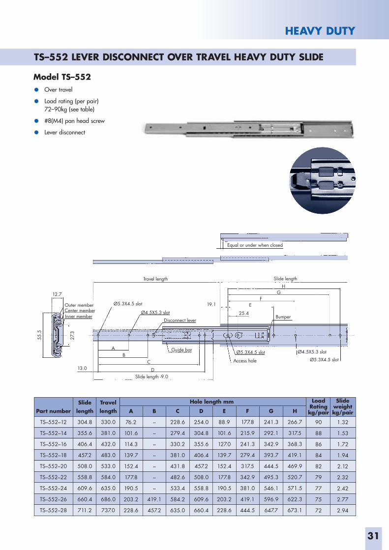
HEAVY DUTY
Outer memberCenter member Inner member
Ø4.5X5.3 slot
Ø4.5X5.3 slot
Guide bar
Disconnect lever
Ø5.3X4.5 slot
Access hole Ø5.3X4.5 slot
Ø5.3X4.5 slot
Travel length
Slide length -9.0
Slide length
Equal or under when closed
12.7
19.1
25.4
13.0
A
FE
HG
Bumper
BC
D
55.5
27.3
Model TS–552
• Over travel
• Load rating (per pair)72–90kg (see table)
• #8(M4) pan head screw
• Lever disconnect
Part number
TS–552–12
TS–552–14
TS–552–16
TS–552–18
TS–552–20
TS–552–22
TS–552–24
TS–552–26
TS–552–28
Slidelength
304.8
355.6
406.4
457.2
508.0
558.8
609.6
660.4
711.2
Travel length
330.0
381.0
432.0
483.0
533.0
584.0
635.0
686.0
737.0
A
76.2
101.6
114.3
139.7
152.4
177.8
190.5
203.2
228.6
C
228.6
279.4
330.2
381.0
431.8
482.6
533.4
584.2
635.0
B
–
–
–
–
–
–
–
419.1
457.2
Hole length mm
D
254.0
304.8
355.6
406.4
457.2
508.0
558.8
609.6
660.4
F
177.8
215.9
241.3
279.4
317.5
342.9
381.0
419.1
444.5
E
88.9
101.6
127.0
139.7
152.4
177.8
190.5
203.2
228.6
G
241.3
292.1
342.9
393.7
444.5
495.3
546.1
596.9
647.7
H
266.7
317.5
368.3
419.1
469.9
520.7
571.5
622.3
673.1
Slide weight kg/pair
1.32
1.53
1.72
1.94
2.12
2.32
2.42
2.77
2.94
LoadRating kg/pair
90
88
86
84
82
79
77
75
72
TS–552 LEVER DISCONNECT OVER TRAVEL HEAVY DUTY SLIDE
32
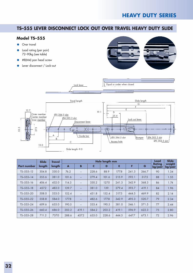
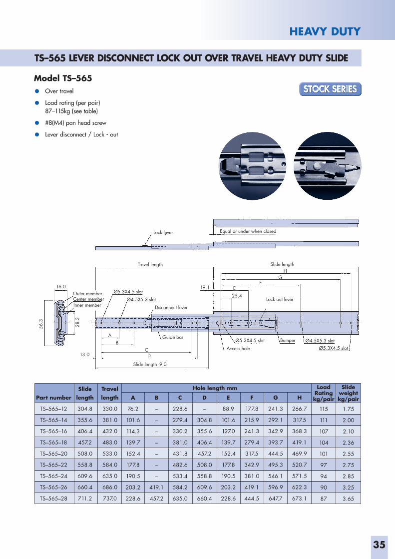
TS–555 LEVER DISCONNECT LOCK OUT OVER TRAVEL HEAVY DUTY SLIDE
HEAVY DUTY SERIES
Part number
TS–555–12
TS–555–14
TS–555–16
TS–555–18
TS–555–20
TS–555–22
TS–555–24
TS–555–26
TS–555–28
Slidelength
304.8
355.6
406.4
457.2
508.0
558.8
609.6
660.4
711.2
Travel length
330.0
381.0
432.0
483.0
533.0
584.0
635.0
686.0
737.0
A
76.2
101.6
114.3
139.7
152.4
177.8
190.5
203.2
288.6
C
228.6
279.4
330.2
381.0
431.8
482.6
533.4
584.2
635.0
B
–
–
–
–
–
–
–
419.1
457.2
Hole length mm
D
88.9
101.6
127.0
139.
152.4
177.8
190.5
203.2
228.6
F
241.3
292.1
342.9
393.7
444.5
495.3
546.1
596.9
647.7
E
177.8
215.9
241.3
279.4
317.5
342.9
381.0
419.1
444.5
G
266.7
317.5
368.3
419.1
469.9
520.7
571.5
622.3
673.1
Slideweight kg/pair
1.34
1.55
1.74
1.96
2.14
2.34
2.44
2.80
2.96
LoadRating kg/pair
90
88
86
84
82
79
77
75
72
Outer memberCenter memberInner member
Ø4.5X5.3 slot
Ø4.5X5.3 slot
Guide bar
Disconnect lever
Ø5.3X4.5 slot
Access hole Ø5.3X4.5 slot
Ø5.3X4.5 slot
Travel length
Lock lever
Slide length -9.0
Slide length
Equal or under when closed
12.719.1
25.4
13.0
A
ED
GF
Lock out lever
BumperBC
55.5
27.3
Model TS–555
• Over travel
• Load rating (per pair)72–90kg (see table)
• #8(M4) pan head screw
• Lever disconnect / Lock-out
33
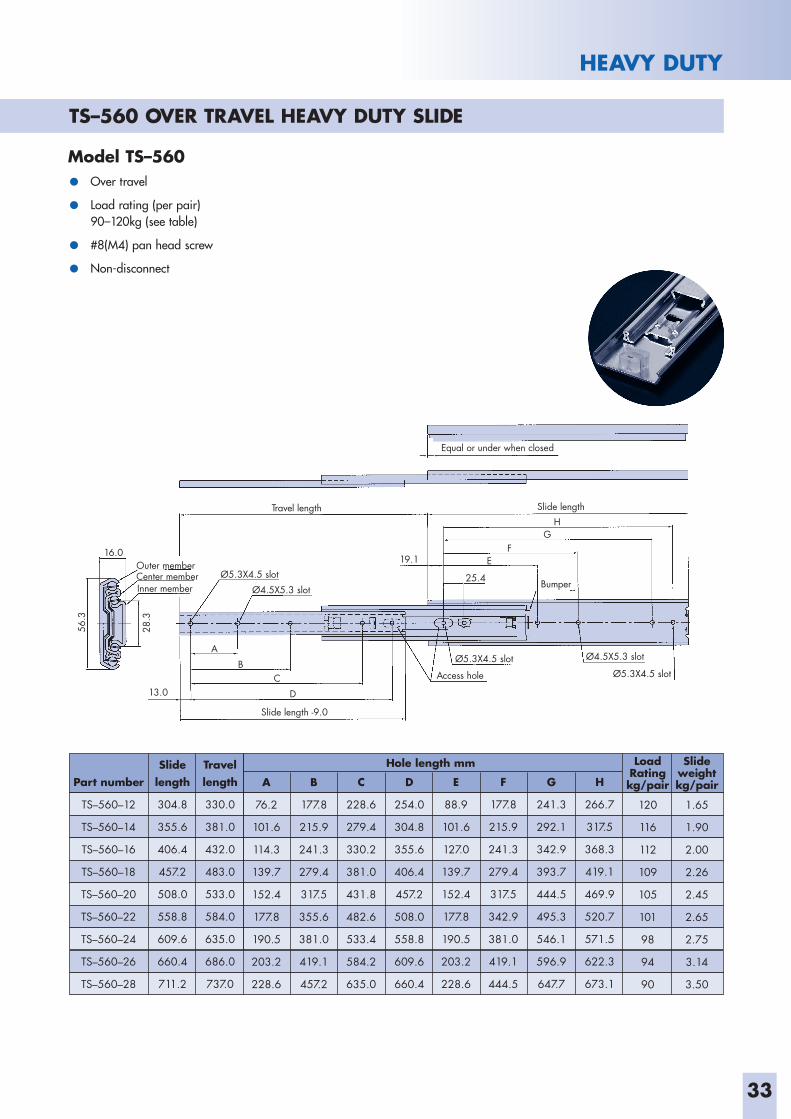
HEAVY DUTY
Outer memberCenter memberInner member
Ø4.5X5.3 slot
Ø4.5X5.3 slot
Ø5.3X4.5 slot
Access hole Ø5.3X4.5 slot
Ø5.3X4.5 slot
Travel length
Slide length -9.0
Slide length
Equal or under when closed
16.0 19.1
25.4
13.0
A
FE
HG
Bumper
BC
D
56.3
28.3
Model TS–560
• Over travel
• Load rating (per pair)90–120kg (see table)
• #8(M4) pan head screw
• Non-disconnect
Part number
TS–560–12
TS–560–14
TS–560–16
TS–560–18
TS–560–20
TS–560–22
TS–560–24
TS–560–26
TS–560–28
Slidelength
304.8
355.6
406.4
457.2
508.0
558.8
609.6
660.4
711.2
Travel length
330.0
381.0
432.0
483.0
533.0
584.0
635.0
686.0
737.0
A
76.2
101.6
114.3
139.7
152.4
177.8
190.5
203.2
228.6
C
228.6
279.4
330.2
381.0
431.8
482.6
533.4
584.2
635.0
B
177.8
215.9
241.3
279.4
317.5
355.6
381.0
419.1
457.2
Hole length mm
D
254.0
304.8
355.6
406.4
457.2
508.0
558.8
609.6
660.4
F
177.8
215.9
241.3
279.4
317.5
342.9
381.0
419.1
444.5
E
88.9
101.6
127.0
139.7
152.4
177.8
190.5
203.2
228.6
G
241.3
292.1
342.9
393.7
444.5
495.3
546.1
596.9
647.7
H
266.7
317.5
368.3
419.1
469.9
520.7
571.5
622.3
673.1
Slide weight kg/pair
1.65
1.90
2.00
2.26
2.45
2.65
2.75
3.14
3.50
LoadRating kg/pair
120
116
112
109
105
101
98
94
90
TS–560 OVER TRAVEL HEAVY DUTY SLIDE
34
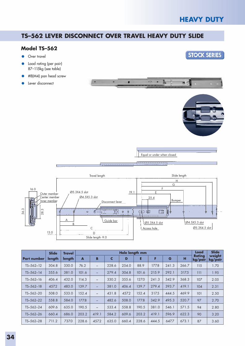
TS–562 LEVER DISCONNECT OVER TRAVEL HEAVY DUTY SLIDE
HEAVY DUTY
Model TS–562
• Over travel
• Load rating (per pair)87–115kg (see table)
• #8(M4) pan head screw
• Lever disconnect
Outer memberCenter memberInner member
Ø4.5X5.3 slot
Ø4.5X5.3 slot
Ø5.3X4.5 slot
Access hole Ø5.3X4.5 slot
Ø5.3X4.5 slot
Travel length
Slide length -9.0
Slide length
Equal or under when closed
16.0 19.1
Disconnect lever
Guide bar
25.4
13.0
A
FE
HG
Bumper
BC
D
56.3
28.3
Part number
TS–562–12
TS–562–14
TS–562–16
TS–562–18
TS–562–20
TS–562–22
TS–562–24
TS–562–26
TS–562–28
Slidelength
304.8
355.6
406.4
457.2
508.0
558.8
609.6
660.4
711.2
Travel length
330.0
381.0
432.0
483.0
533.0
584.0
635.0
686.0
737.0
A
76.2
101.6
114.3
139.7
152.4
177.8
190.5
203.2
228.6
C
228.6
279.4
330.2
381.0
431.8
482.6
533.4
584.2
635.0
B
–
–
–
–
–
–
–
419.1
457.2
Hole length mm
D
254.0
304.8
355.6
406.4
457.2
508.0
558.8
609.6
660.4
F
177.8
215.9
241.3
279.4
317.5
342.9
381.0
419.1
444.5
E
88.9
101.6
127.0
139.7
152.4
177.8
190.5
203.2
228.6
G
241.3
292.1
342.9
393.7
444.5
495.3
546.1
596.9
647.7
H
266.7
317.5
368.3
419.1
469.9
520.7
571.5
622.3
673.1
Slideweight kg/pair
1.70
1.95
2.05
2.31
2.50
2.70
2.80
3.20
3.60
LoadRating kg/pair
115
111
107
104
101
97
94
90
87
35
HEAVY DUTY
Part number
TS–565–12
TS–565–14
TS–565–16
TS–565–18
TS–565–20
TS–565–22
TS–565–24
TS–565–26
TS–565–28
Slidelength
304.8
355.6
406.4
457.2
508.0
558.8
609.6
660.4
711.2
Travel length
330.0
381.0
432.0
483.0
533.0
584.0
635.0
686.0
737.0
A
76.2
101.6
114.3
139.7
152.4
177.8
190.5
203.2
228.6
C
228.6
279.4
330.2
381.0
431.8
482.6
533.4
584.2
635.0
B
–
–
–
–
–
–
–
419.1
457.2
Hole length mm
D
–
304.8
355.6
406.4
457.2
508.0
558.8
609.6
660.4
F
177.8
215.9
241.3
279.4
317.5
342.9
381.0
419.1
444.5
E
88.9
101.6
127.0
139.7
152.4
177.8
190.5
203.2
228.6
G
241.3
292.1
342.9
393.7
444.5
495.3
546.1
596.9
647.7
H
266.7
317.5
368.3
419.1
469.9
520.7
571.5
622.3
673.1
Slide weight kg/pair
1.75
2.00
2.10
2.36
2.55
2.75
2.85
3.25
3.65
LoadRating kg/pair
115
111
107
104
101
97
94
90
87
Outer memberCenter memberInner member
Ø4.5X5.3 slot
Ø4.5X5.3 slot
Disconnect lever
Guide bar Ø5.3X4.5 slot
Access hole Ø5.3X4.5 slot
Ø5.3X4.5 slot
Travel length
Slide length -9.0
Slide length
Equal or under when closed
16.0 19.1
25.4
13.0
A
FE
HG
Lock out lever
Bumper
Lock lever
BCD
56.3
28.3
Model TS–565
• Over travel
• Load rating (per pair)87–115kg (see table)
• #8(M4) pan head screw
• Lever disconnect / Lock - out
TS–565 LEVER DISCONNECT LOCK OUT OVER TRAVEL HEAVY DUTY SLIDE
36
Notes
37
Notes
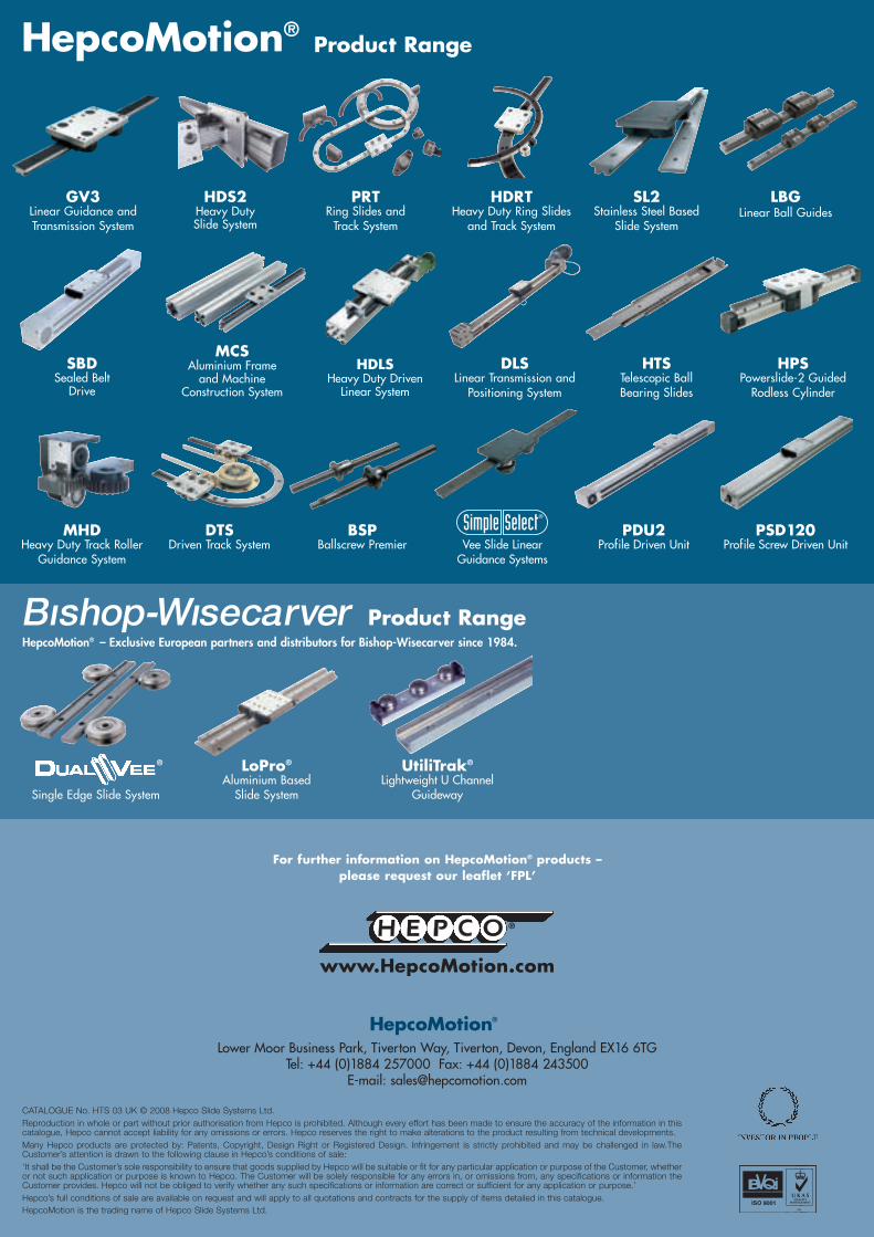
Single Edge Slide System
Lower Moor Business Park, Tiverton Way, Tiverton, Devon, England EX16 6TGTel: +44 (0)1884 257000 Fax: +44 (0)1884 243500
E-mail: [email protected]
HepcoMotion®
For further information on HepcoMotion® products –please request our leaflet ‘FPL’
CATALOGUE No. HTS 03 UK © 2008 Hepco Slide Systems Ltd.Reproduction in whole or part without prior authorisation from Hepco is prohibited. Although every effort has been made to ensure the accuracy of the information in thiscatalogue, Hepco cannot accept liability for any omissions or errors. Hepco reserves the right to make alterations to the product resulting from technical developments.Many Hepco products are protected by: Patents, Copyright, Design Right or Registered Design. Infringement is strictly prohibited and may be challenged in law.TheCustomer’s attention is drawn to the following clause in Hepco’s conditions of sale:‘It shall be the Customer’s sole responsibility to ensure that goods supplied by Hepco will be suitable or fit for any particular application or purpose of the Customer, whetheror not such application or purpose is known to Hepco. The Customer will be solely responsible for any errors in, or omissions from, any specifications or information theCustomer provides. Hepco will not be obliged to verify whether any such specifications or information are correct or sufficient for any application or purpose.’Hepco’s full conditions of sale are available on request and will apply to all quotations and contracts for the supply of items detailed in this catalogue.HepcoMotion is the trading name of Hepco Slide Systems Ltd.
LoPro®
Aluminium BasedSlide System
HepcoMotion® – Exclusive European partners and distributors for Bishop-Wisecarver since 1984.
Product Range
®
HPSPowerslide-2 GuidedRodless Cylinder
BSPBallscrew Premier
MCSAluminium Frameand Machine
Construction System
MHDHeavy Duty Track Roller
Guidance System
SBDSealed Belt
Drive
Vee Slide LinearGuidance Systems
PDU2Profile Driven Unit
HepcoMotion®Product Range
HDLSHeavy Duty Driven
Linear System
SL2Stainless Steel Based
Slide System
PRTRing Slides andTrack System
HTSTelescopic BallBearing Slides
LBGLinear Ball Guides
PSD120Profile Screw Driven Unit
HDRTHeavy Duty Ring Slides
and Track System
GV3Linear Guidance andTransmission System
HDS2Heavy DutySlide System
DLSLinear Transmission and
Positioning System
DTSDriven Track System
UtiliTrak®
Lightweight U ChannelGuideway