Embed Size (px)
Citation preview
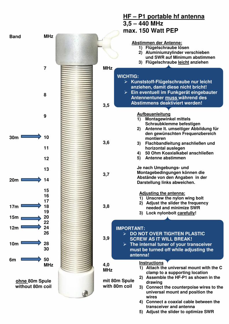
MHz 7 8 9 10 11 12 13 14 15 16 17 18 19 20 22 24 26 28 30 50 MHz
Band 30m 20m 17m 15m 12m 10m 6m
ohne 80m Spule without 80m coil
MHz 3,5 3,6 3,7 3,8 3,9 4,0 MHz mit 80m Spule with 80m coil
Abstimmen der Antenne: 1) Flügelschraube lösen 2) Aluminiumzylinder verschieben
und SWR auf Minimum abstimmen 3) Flügelschraube leicht anziehen
HF – P1 portable hf antenna 3,5 – 440 MHz max. 150 Watt PEP
Aufbauanleitung 1) Montagewinkel mittels
Schraubklemme befestigen 2) Antenne lt. umseitiger Abbildung für
den gewünschten Frequenzbereich montieren
3) Flachbandleitung anschließen und horizontal auslegen
4) 50 Ohm Koaxialkabel anschließen 5) Antenne abstimmen Je nach Umgebungs- und Montagebedingungen können die Abstände von den Angaben in der Darstellung links abweichen.
Adjusting the antenna: 1) Unscrew the nylon wing bolt 2) Adjust the slider the frequency
needed and minimize SWR
3) Lock nylonbolt carefully!
Instructions 1) Attach the universal mount with the C
clamp to a supporting location 2) Assemble the HF-P1 as shown in the
drawing 3) Connect the counterpoise wires to the
universal mount and position the wires
4) Connect a coaxial cable between the transceiver and antenna
5) Adjust the slider to optimize SWR
WICHTIG: � Kunststoff-Flügelschraube nur leicht
anziehen, damit diese nicht bricht! � Ein eventuell im Funkgerät eingebauter
Antennentuner muss während des Abstimmens deaktiviert werden!
IMPORTANT: � DO NOT OVER TIGHTEN PLASTIC
SCREW AS IT WILL BREAK! � The internal tuner of your transceiver
must be turned off while adjusting the antenna!
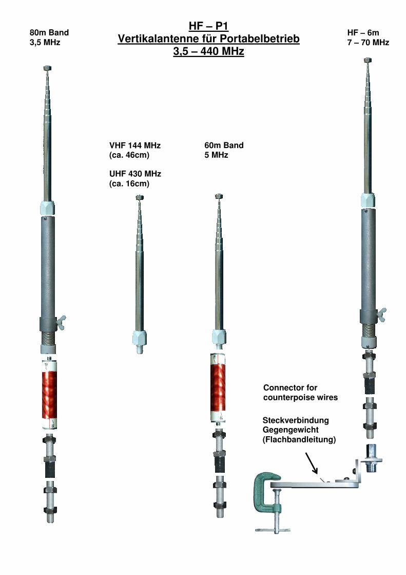
80m Band 3,5 MHz
HF – 6m 7 – 70 MHz
VHF 144 MHz (ca. 46cm) UHF 430 MHz (ca. 16cm)
Steckverbindung Gegengewicht (Flachbandleitung)
60m Band 5 MHz
HF – P1 Vertikalantenne für Portabelbetrieb
3,5 – 440 MHz
Connector for counterpoise wires


![HF spectrum occupancy and antennas - University of Leicester1].pdf · Key words Antenna Analysis – Antenna Synthesis ... When a distribution of point sources is giv- ... for a continuous](https://img.pdfslide.tips/doc/110x75/5af1d8287f8b9ac2468fd8fa/hf-spectrum-occupancy-and-antennas-university-of-leicester-1pdfkey-words-antenna.jpg)