Embed Size (px)
DESCRIPTION
oily water separator marine type 15 ppm bilge separator model HFM
Citation preview
HFM TYPE
OPERATION MANUAL FOR
15ppm BILGE SEPARATOR
Dec. 2011
HEISHIN PUMP WORKS CO. ,LTD
12-06-04
OPERATION MANUAL
FOR
HFM-MODEL 15PPM BILGE SEPARATOR
CONTENTS
1. Construction of the HFM-model 15ppm Bilge Separator ··································· 1
2. Recommended bilge pump ················································································· 3
3. Operation ············································································································ 4
4. Suspension of operation ····················································································· 4
5. Special note during operation ············································································· 5
6. Maintenance ······································································································· 5
7. Trouble Shooting ··································································································· 13
8. Important note for maintenance ·········································································· 16
9. Other factor for separation efficiency ································································· 19
* * * * * * * *
- 1 -
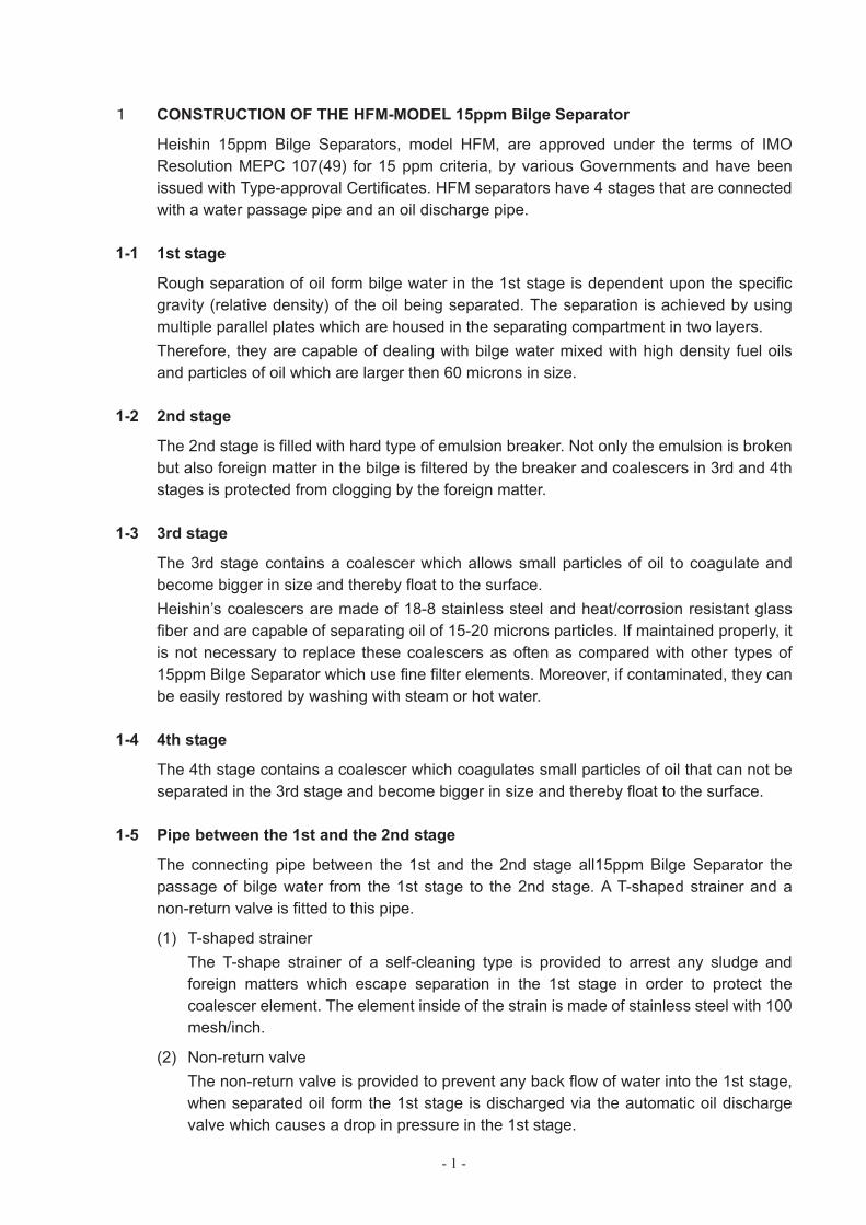
CONSTRUCTION OF THE HFM-MODEL 15ppm Bilge Separator
Heishin 15ppm Bilge Separators, model HFM, are approved under the terms of IMO Resolution MEPC 107(49) for 15 ppm criteria, by various Governments and have been issued with Type-approval Certificates. HFM separators have 4 stages that are connected with a water passage pipe and an oil discharge pipe.
1-1 1st stage
Rough separation of oil form bilge water in the 1st stage is dependent upon the specific gravity (relative density) of the oil being separated. The separation is achieved by using multiple parallel plates which are housed in the separating compartment in two layers. Therefore, they are capable of dealing with bilge water mixed with high density fuel oils and particles of oil which are larger then 60 microns in size.
1-2 2nd stage
The 2nd stage is filled with hard type of emulsion breaker. Not only the emulsion is broken but also foreign matter in the bilge is filtered by the breaker and coalescers in 3rd and 4th stages is protected from clogging by the foreign matter.
1-3 3rd stage
The 3rd stage contains a coalescer which allows small particles of oil to coagulate and become bigger in size and thereby float to the surface. Heishin’s coalescers are made of 18-8 stainless steel and heat/corrosion resistant glass fiber and are capable of separating oil of 15-20 microns particles. If maintained properly, it is not necessary to replace these coalescers as often as compared with other types of 15ppm Bilge Separator which use fine filter elements. Moreover, if contaminated, they can be easily restored by washing with steam or hot water.
1-4 4th stage
The 4th stage contains a coalescer which coagulates small particles of oil that can not be separated in the 3rd stage and become bigger in size and thereby float to the surface.
1-5 Pipe between the 1st and the 2nd stage
The connecting pipe between the 1st and the 2nd stage all15ppm Bilge Separator the passage of bilge water from the 1st stage to the 2nd stage. A T-shaped strainer and a non-return valve is fitted to this pipe.
(1) T-shaped strainer The T-shape strainer of a self-cleaning type is provided to arrest any sludge and foreign matters which escape separation in the 1st stage in order to protect the coalescer element. The element inside of the strain is made of stainless steel with 100 mesh/inch.
(2) Non-return valve The non-return valve is provided to prevent any back flow of water into the 1st stage, when separated oil form the 1st stage is discharged via the automatic oil discharge valve which causes a drop in pressure in the 1st stage.
- 2 -
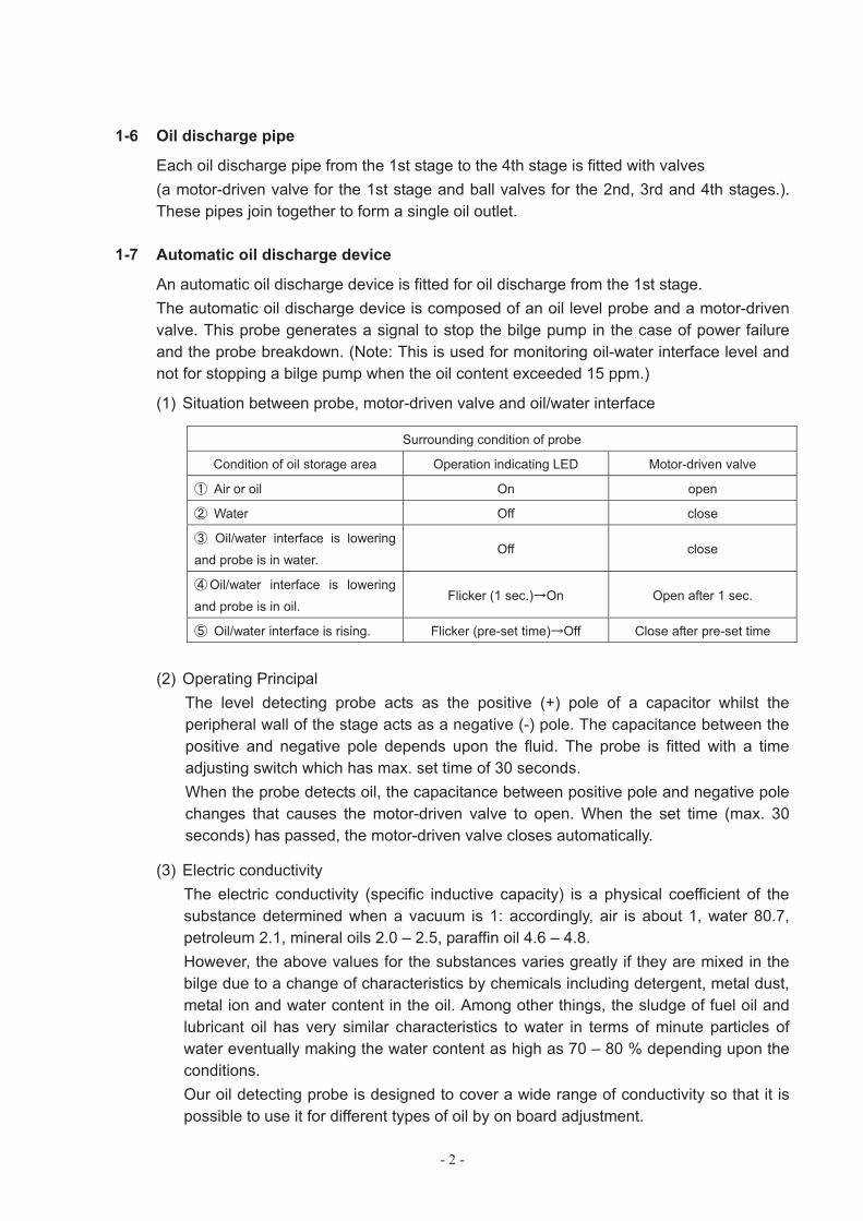
1-6 Oil discharge pipe
Each oil discharge pipe from the 1st stage to the 4th stage is fitted with valves (a motor-driven valve for the 1st stage and ball valves for the 2nd, 3rd and 4th stages.). These pipes join together to form a single oil outlet.
1-7 Automatic oil discharge device
An automatic oil discharge device is fitted for oil discharge from the 1st stage. The automatic oil discharge device is composed of an oil level probe and a motor-driven valve. This probe generates a signal to stop the bilge pump in the case of power failure and the probe breakdown. (Note: This is used for monitoring oil-water interface level and not for stopping a bilge pump when the oil content exceeded 15 ppm.)
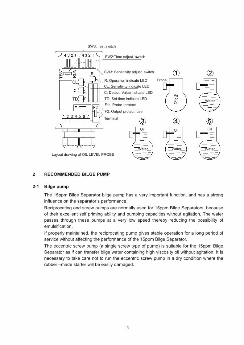
(1) Situation between probe, motor-driven valve and oil/water interface
Surrounding condition of probe
Condition of oil storage area Operation indicating LED Motor-driven valve
Air or oil On open
Water Off close
Oil/water interface is lowering
and probe is in water. Off close
Oil/water interface is lowering
and probe is in oil. Flicker (1 sec.) On Open after 1 sec.
Oil/water interface is rising. Flicker (pre-set time) Off Close after pre-set time
(2) Operating Principal The level detecting probe acts as the positive (+) pole of a capacitor whilst the peripheral wall of the stage acts as a negative (-) pole. The capacitance between the positive and negative pole depends upon the fluid. The probe is fitted with a time adjusting switch which has max. set time of 30 seconds. When the probe detects oil, the capacitance between positive pole and negative pole changes that causes the motor-driven valve to open. When the set time (max. 30 seconds) has passed, the motor-driven valve closes automatically.
(3) Electric conductivity The electric conductivity (specific inductive capacity) is a physical coefficient of the substance determined when a vacuum is 1: accordingly, air is about 1, water 80.7, petroleum 2.1, mineral oils 2.0 – 2.5, paraffin oil 4.6 – 4.8. However, the above values for the substances varies greatly if they are mixed in the bilge due to a change of characteristics by chemicals including detergent, metal dust, metal ion and water content in the oil. Among other things, the sludge of fuel oil and lubricant oil has very similar characteristics to water in terms of minute particles of water eventually making the water content as high as 70 – 80 % depending upon the conditions. Our oil detecting probe is designed to cover a wide range of conductivity so that it is possible to use it for different types of oil by on board adjustment.
- 3 -
2 RECOMMENDED BILGE PUMP
2-1 Bilge pump
The 15ppm Bilge Separator bilge pump has a very important function, and has a strong influence on the separator’s performance. Reciprocating and screw pumps are normally used for 15ppm Bilge Separators, because of their excellent self priming ability and pumping capacities without agitation. The water passes through these pumps at a very low speed thereby reducing the possibility of emulsification. If properly maintained, the reciprocating pump gives stable operation for a long period of service without affecting the performance of the 15ppm Bilge Separator. The eccentric screw pump (a single screw type of pump) is suitable for the 15ppm Bilge Separator as if can transfer bilge water containing high viscosity oil without agitation. It is necessary to take care not to run the eccentric screw pump in a dry condition where the rubber –made starter will be easily damaged.
SW3: Test switch
SW2:Time adjust. switch
SW3: Sensitivity adjust. switch
R: Operation indicate LED CL: Sensitivity indicate LED
C: Detect. Value indicate LED
TD: Set time indicate LEDF1: Probe protect
F2: Output protect fuse
Terminal
Probe
AirorOil
Oil
Water
Water
Oil
Water
Oil
WaterLayout drawing of OIL LEVEL PROBE
- 4 -
3 OPERATION
3-1 Preparation for operation
Prior to operating the 15ppm Bilge Separator after installation, it is necessary to ensure the following:
1. Piping for the 15ppm Bilge Separator is laid down in accordance with the manufacture’s piping arrangement, and the specification of ship owner/shipyard if provided.
2. The electric wiring of power supply and alarm signal for 15ppm Bilge Separator is correctly made.
3. For cleaning inside the pipe from the suction line to the inlet of 15ppm Bilge Separator, flush with seawater by running bilge pump. (In this step, seawater is not to be supplied to 15ppm Bilge Separator)
4. After elimination of sludge, mud and dirt in the pipe, confirm that there is no leakage from the pipe and the system.
5. 15ppm Bilge Separator is filled up with seawater by bilge pump 6. No leakage should be observed from the pipe before the 15ppm Bilge Separator.
3-2 Operation
Procedures for daily service of 15ppm Bilge Separator:
1. Turn on the power supply to the automatic oil discharge device.
2. Open all the valves fitted to the bilge discharge pipe line and start the bilge pump.
CautionWhere the 15ppm Bilge Separator has been unused for more than one week, flush the 15ppm Bilge Separator with seawater using bilge pump for 15 - 20 minutes prior to handling the bilge. This is because oil, suspended solids (SS), sediment and bacteria staying in the 15ppm Bilge Separator may have changed into containments by biochemical reaction and affect the 15ppm Bilge Separator’s performance.
3. During the operation of the 15ppm Bilge Separator, oil is separated from bilge water and accumulates at the upper part of each stage, and eventually this separated oil should be discharged into the waste oil tank. The separated oil in the 1st stage is discharged automatically by an automatic oildischarge device. Oil in the 2nd, 3rd and 4th stages, however, must be discharged manually at any time when considered necessary upon checking by the test cock fitted to the stage. The recommended time for oil discharge is 2 - 3 minutes.
4 SUSPENSION OF OPERATION
In finishing the operation,
1. Flush the 15ppm Bilge Separator with seawater for about 15 minutes. 2. Stop the bilge pump, and switch off the electric power supply. 3. Ensure that the 15ppm Bilge Separator is kept full of water and should not be emptied
whilst it is unused.
- 5 -
5 SPECIAL NOTE DURING OPERATION
5-1 Cleaning of T-shape strainer
Since the bilge water contains sludge and solids and solids which often choke up the coalescer element, it is important to clean the strainer from time to time. The strainer can be easily cleaned by rotating the handle provided at the top, during operation. The foreign matter removed form the strainer element should be discharged out of the strainer by opening the ball valve fitted on the bottom of the strainer for 5 – 10 seconds. Although the frequency of cleaning service depends upon the ship’s condition, for safety sake cleaning should be better done at every operation.
See 6 - 1 (1) for maintenance.
6 MAINTENANCE
In order to keep the performance and function of the 15ppm Bilge Separator in good condition, proper maintenance is always required considering the bilge water contains a variety of contaminants including waste oil, sludge, suspended solids (SS), chemical substance, bacteria, etc. all in different forms.
6-1 Routine check
1. For the bilge pump
(1) Clean up the strainer fitted to the suction side. (2) Check the vibration, noise and pressure. (3) In case the bilge pump is driven by V-belt, check the tension is correct. (4) Check the temperature of the bearing. When the temperature rises too high to touch
the bearing case by hand, check the bearing itself and bearing housing. (5) Tighten the gland packing if there is a leakage.
2. For the 15ppm Bilge Separator
(1) Check the pressure difference between the 1st and 3rd stage. When the pressure difference is more than 0.07 – 0.1 MPa;
(a) Clean up the T-shape strainer. (b) For cleaning, turn the handle by hand 4 - 5 times and drain the sludge form the
bottom of the strainer using the ball valve during the operation. (c) If the pressure difference does not decrease, wash the coalescer of the 3rd stage
in accordance with 6 - 2.
(2) Check if there is no leakage from the separator body. (3) Check the function of the automatic oil discharge device.
- 6 -
6-2 Washing
HFM-model 15ppm Bilge Separator is provided with a washing port fitted on the front cover of the 1st stage and at the inlet pipe of the 3rd stage. The 15ppm Bilge Separator should be washed with steam (or hot water) periodically once a month or whenever considered necessary. Washing can done for both stages either at one time or one stage at a time.
Washing process:
1. Ensure that the separator is filled up with either bilge or seawater. 2. Connect the steam line to the washing port. 3. Open the motor-driven valve of the 1st stage manually in accordance with 7 - 4 and
also open the oil discharge valves of the 2nd, 3rd and 4th stages.
Important Note !!
Keep these two valves open until the washing out process finishes.
4. Run the bilge pump for a short time to discharge separated oil from one by one stage. 5. Supply live steam (or hot water) in order to heat up water in the 15ppm Bilge Separator
up to 70 - 80 . When the temperature rises, stop the supply of steam and keep the 15ppm Bilge Separator in this condition for 2 hours.
6. Run the bilge pump for 2 - 3 minutes to discharge the remaining oil. 7. Drain the water of only the 1st stage to the bilge well from the bottom of the stage.
When draining the water out of the 2nd, 3rd and 4th stages, ensure that separated oil has been completely discharged out of the stage.
8. Close all valves but open the valves on the pipe for bilge treatment if closed. 9. Start the operation of the 15ppm Bilge Separator for bilge.
Caution
The 15ppm Bilge Separator should be filled with seawater prior to the switch over to bilge. Washing is completed when seawater is fed into the system.
Important note !!
1. When the 15ppm Bilge Separator is first used, the pressure loss in the coalescer in the 3rd stage is about 0.01 MPa.
2. When the pressure difference becomes more than 0.07 – 0.1 MPa, washing should be carried out. There should be no problem if the pressure loss in the coalescer is over 0.01 MPa even after washing unless it is more than 0.05 MPa.
3. Direct and thorough cleaning by complete dismantle and overhauling of the coalescer should be done provided the pressure loss is over 0.05 MPa after steam or hot water washing.
4. It is necessary to replace the existing coalescer in the 3rd stage with a new one if;
(1) the pressure loss still remains over 0.05 MPa after cleaning by overhaul, or (2) any damage to the coalescer is observed.
- 7 -
6-3 2nd stage
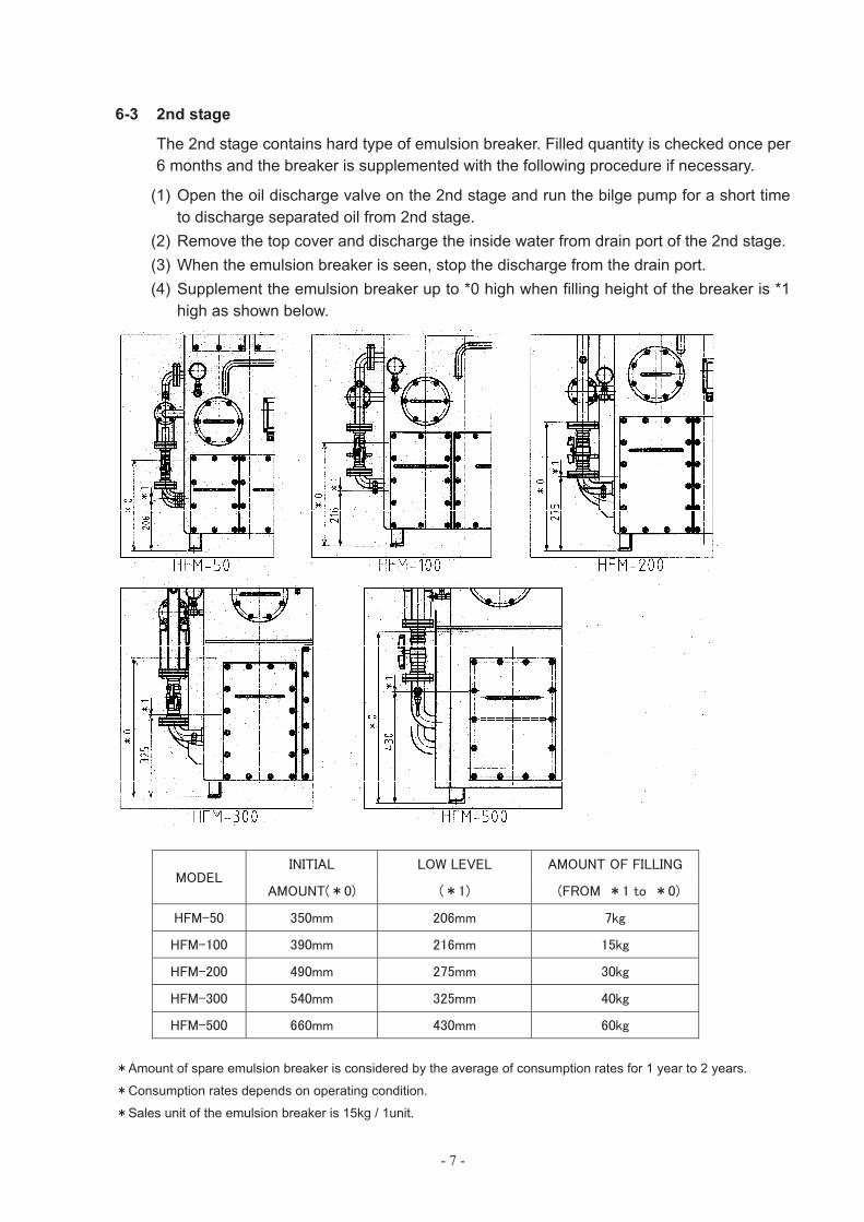
The 2nd stage contains hard type of emulsion breaker. Filled quantity is checked once per 6 months and the breaker is supplemented with the following procedure if necessary.
(1) Open the oil discharge valve on the 2nd stage and run the bilge pump for a short time to discharge separated oil from 2nd stage.
(2) Remove the top cover and discharge the inside water from drain port of the 2nd stage. (3) When the emulsion breaker is seen, stop the discharge from the drain port. (4) Supplement the emulsion breaker up to *0 high when filling height of the breaker is *1
high as shown below.
Amount of spare emulsion breaker is considered by the average of consumption rates for 1 year to 2 years.
Consumption rates depends on operating condition.
Sales unit of the emulsion breaker is 15kg / 1unit.
- 8 -
6-4 Overhaul and inspection
Prior to overhauling, it is recommended that washing by steam is carried out and separated oil in all stages is discharged.
1. 1st stage
(1) Disconnect the influence inlet pipe fitted to the body of the stages. (2) Unbolt the right body to remove it from the main body. (3) Unbolt the inner cover for the parallel plates section and remove it. (4) After removing the front cover, pull out all the parallel.
At the centre of each parallel plates, there is a hole with which the plate can be pulled out.
(5) Zinc anodes fitted inside the front cover should have an visual inspection at least once every 6 months.
Please replace with new ones if heavily corroded.
2. 2nd stage
(1) Unbolt the manhole cover and emulsion breaker can be pull out. (2) Remove the top cover in order to check inside condition of the stage.
3. 3rd stage
(1) Unbolt flange on the body flange of right side to pull out the coalescer complete.
(2) Zinc anodes fitted inside the front cover should have an visual inspection at least once every 6 months.
Please replace with new ones if heavily corroded.
4. 4th stage
Remove the top cover to pull out the coalescer element.
5. Clean each component and inside the wall of the stage by wiping off or washing with light oil if necessary. Special attention should be given to check if corrosion has occurred.
6. If any damage is found, repair it properly.
(a) When replacing a gasket with a new one, the flange face should be cleaned up. (b) When replacing the internal coating, first clean the damaged or peeled off parts
thoroughly and repaint with epoxy tar on the oil-and rust-free surface. Dry the coating completely prior to re-assembly.
7. Re-assemble the 15ppm Bilge Separator exactly in the reveres order to the disassembly.
8. Carry out a leakage check test after re-assembly.
- 9 -
6-5 Adjustment of oil level probe
The automatic oil discharge device has already been adjusted at our workshop before shipment, and generally no further adjustment is necessary before 15ppm Bilge Separator is put into operation. Should further adjustment be required for some reasons the following re-adjustment can be feasible only when the 15ppm Bilge Separator is full of seawater:
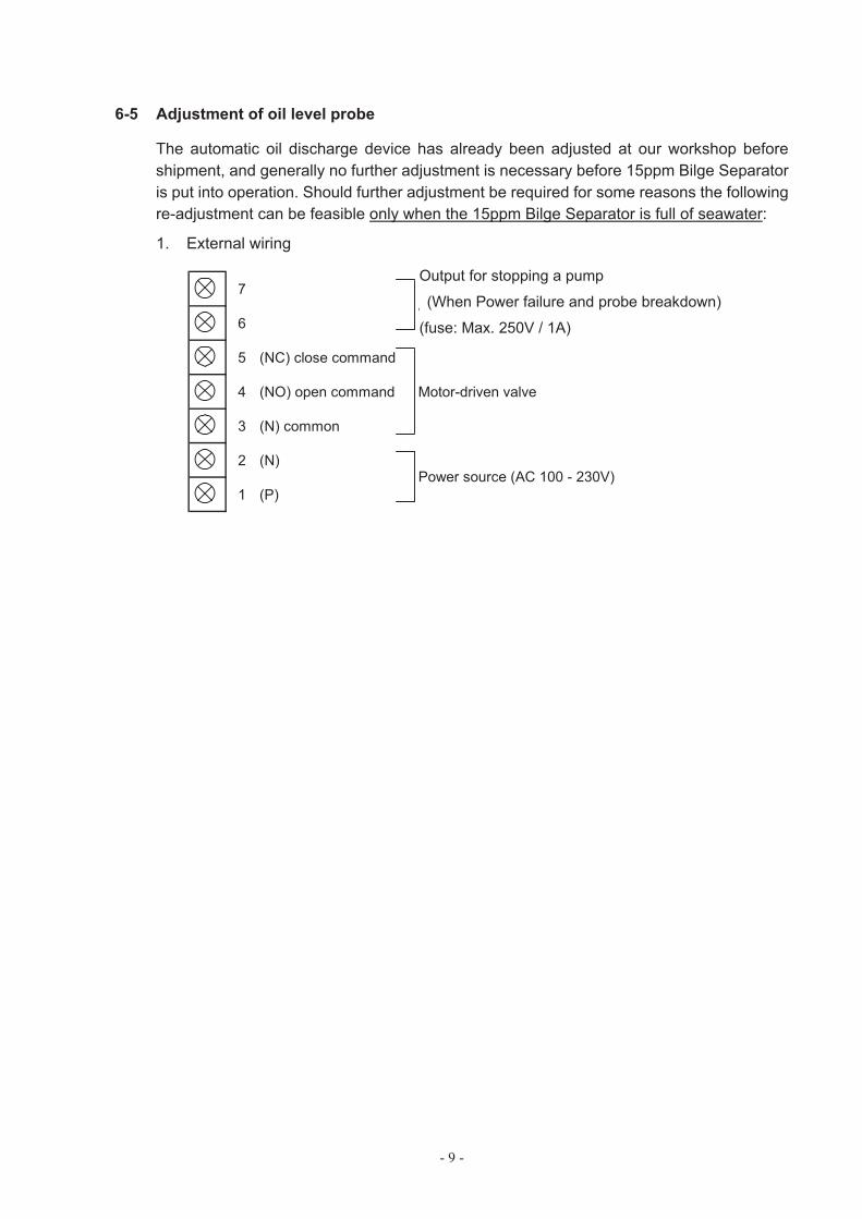
1. External wiring
7
6
5 (NC) close command
4 (NO) open command Motor-driven valve
3 (N) common
2 (N)
1 (P)
Alarm output (fuse: Max. 1A)
Power source (AC 100 - 230V)
Output for stopping a pump
(When Power failure and probe breakdown)
(fuse: Max. 250V / 1A)
- 10 -
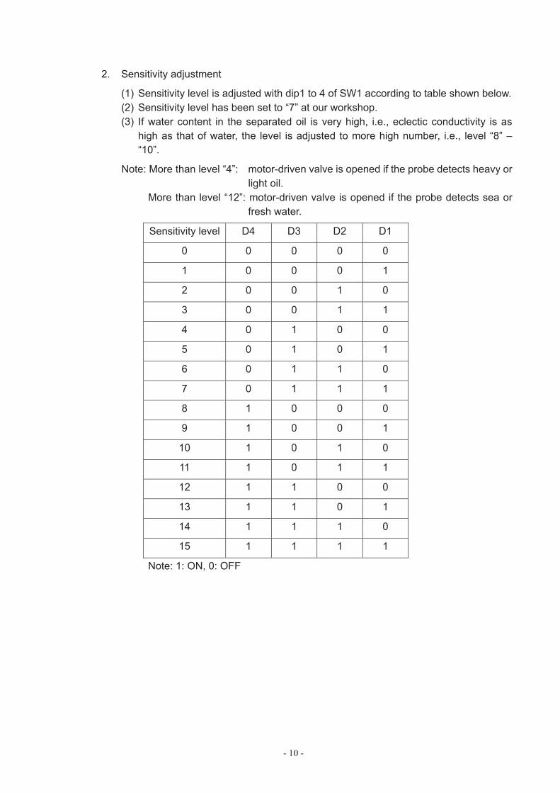
2. Sensitivity adjustment
(1) Sensitivity level is adjusted with dip1 to 4 of SW1 according to table shown below. (2) Sensitivity level has been set to “7” at our workshop. (3) If water content in the separated oil is very high, i.e., eclectic conductivity is as
high as that of water, the level is adjusted to more high number, i.e., level “8” – “10”.
Note: More than level “4”: motor-driven valve is opened if the probe detects heavy or light oil.
More than level “12”: motor-driven valve is opened if the probe detects sea or fresh water.
Sensitivity level D4 D3 D2 D1
0 0 0 0 0
1 0 0 0 1
2 0 0 1 0
3 0 0 1 1
4 0 1 0 0
5 0 1 0 1
6 0 1 1 0
7 0 1 1 1
8 1 0 0 0
9 1 0 0 1
10 1 0 1 0
11 1 0 1 1
12 1 1 0 0
13 1 1 0 1
14 1 1 1 0
15 1 1 1 1
Note: 1: ON, 0: OFF
- 11 -
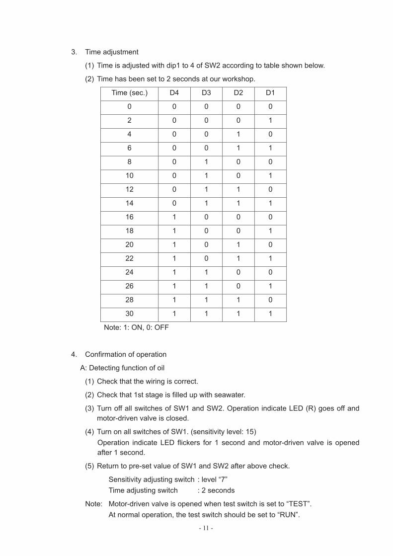
3. Time adjustment
(1) Time is adjusted with dip1 to 4 of SW2 according to table shown below.
(2) Time has been set to 2 seconds at our workshop.
Time (sec.) D4 D3 D2 D1
0 0 0 0 0
2 0 0 0 1
4 0 0 1 0
6 0 0 1 1
8 0 1 0 0
10 0 1 0 1
12 0 1 1 0
14 0 1 1 1
16 1 0 0 0
18 1 0 0 1
20 1 0 1 0
22 1 0 1 1
24 1 1 0 0
26 1 1 0 1
28 1 1 1 0
30 1 1 1 1
Note: 1: ON, 0: OFF
4. Confirmation of operation
A: Detecting function of oil
(1) Check that the wiring is correct.
(2) Check that 1st stage is filled up with seawater.
(3) Turn off all switches of SW1 and SW2. Operation indicate LED (R) goes off and motor-driven valve is closed.
(4) Turn on all switches of SW1. (sensitivity level: 15) Operation indicate LED flickers for 1 second and motor-driven valve is opened after 1 second.
(5) Return to pre-set value of SW1 and SW2 after above check.
Sensitivity adjusting switch : level “7” Time adjusting switch : 2 seconds
Note: Motor-driven valve is opened when test switch is set to “TEST”. At normal operation, the test switch should be set to “RUN”.
- 12 -
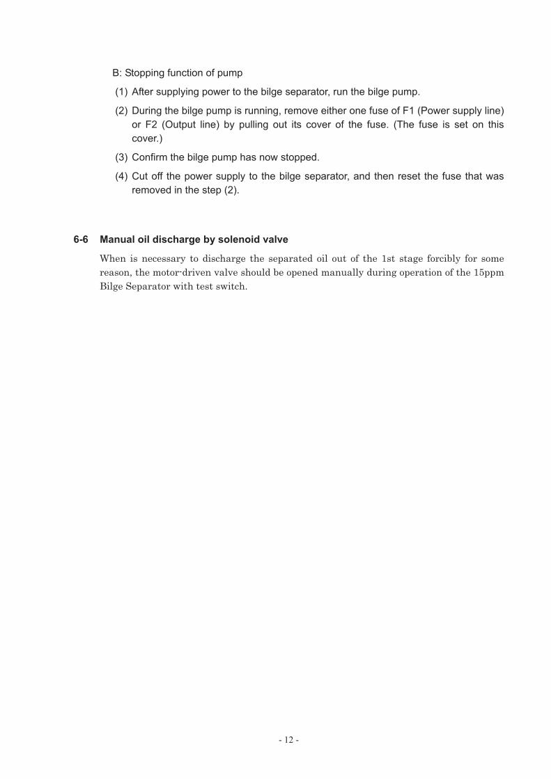
B: Stopping function of pump
(1) After supplying power to the bilge separator, run the bilge pump.
(2) During the bilge pump is running, remove either one fuse of F1 (Power supply line) or F2 (Output line) by pulling out its cover of the fuse. (The fuse is set on this cover.)
(3) Confirm the bilge pump has now stopped.
(4) Cut off the power supply to the bilge separator, and then reset the fuse that was removed in the step (2).
6-6 Manual oil discharge by solenoid valve
When is necessary to discharge the separated oil out of the 1st stage forcibly for some reason, the motor-driven valve should be opened manually during operation of the 15ppm Bilge Separator with test switch.
- 13 -
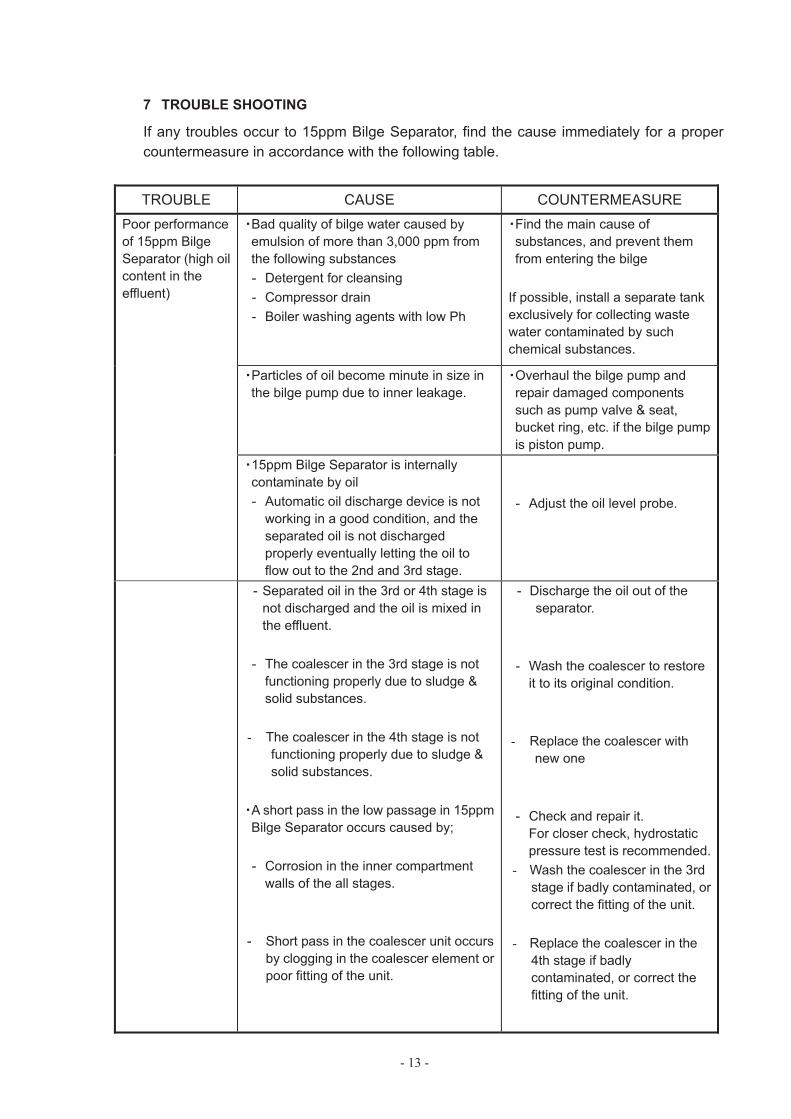
7 TROUBLE SHOOTING
If any troubles occur to 15ppm Bilge Separator, find the cause immediately for a proper countermeasure in accordance with the following table.
TROUBLE CAUSE COUNTERMEASURE Poor performance of 15ppm Bilge Separator (high oil content in the effluent)
Bad quality of bilge water caused by emulsion of more than 3,000 ppm from the following substances - Detergent for cleansing - Compressor drain - Boiler washing agents with low Ph
Find the main cause of substances, and prevent them from entering the bilge
If possible, install a separate tank exclusively for collecting waste water contaminated by such chemical substances.
Particles of oil become minute in size in the bilge pump due to inner leakage.
Overhaul the bilge pump and repair damaged components such as pump valve & seat, bucket ring, etc. if the bilge pump is piston pump.
15ppm Bilge Separator is internally contaminate by oil - Automatic oil discharge device is not
working in a good condition, and the separated oil is not discharged properly eventually letting the oil to flow out to the 2nd and 3rd stage.
- Adjust the oil level probe.
- Separated oil in the 3rd or 4th stage is not discharged and the oil is mixed in the effluent.
- The coalescer in the 3rd stage is not functioning properly due to sludge & solid substances.
- The coalescer in the 4th stage is not functioning properly due to sludge & solid substances.
A short pass in the low passage in 15ppm Bilge Separator occurs caused by;
- Corrosion in the inner compartment walls of the all stages.
- Short pass in the coalescer unit occurs by clogging in the coalescer element or poor fitting of the unit.
- Discharge the oil out of the separator.
- Wash the coalescer to restore it to its original condition.
- Replace the coalescer with new one
- Check and repair it. For closer check, hydrostatic pressure test is recommended.
- Wash the coalescer in the 3rd stage if badly contaminated, or correct the fitting of the unit.
- Replace the coalescer in the 4th stage if badly contaminated, or correct the fitting of the unit.
- 14 -
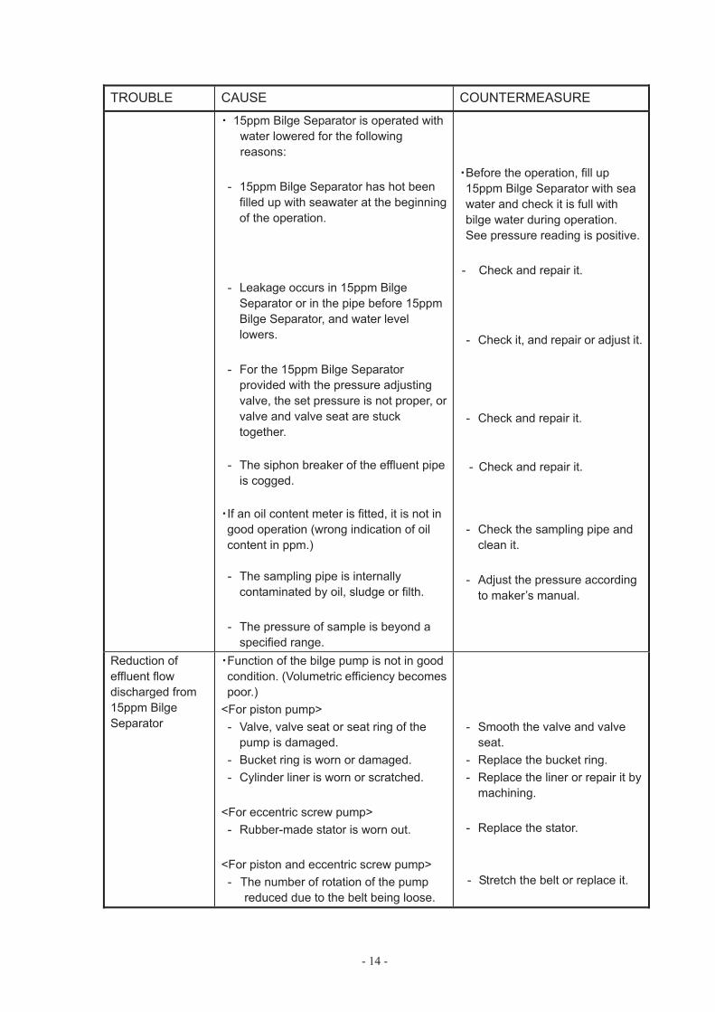
TROUBLE CAUSE COUNTERMEASURE
15ppm Bilge Separator is operated with water lowered for the following reasons:
- 15ppm Bilge Separator has hot been filled up with seawater at the beginning of the operation.
- Leakage occurs in 15ppm Bilge Separator or in the pipe before 15ppm Bilge Separator, and water level lowers.
- For the 15ppm Bilge Separator provided with the pressure adjusting valve, the set pressure is not proper, or valve and valve seat are stuck together.
- The siphon breaker of the effluent pipeis cogged.
If an oil content meter is fitted, it is not in good operation (wrong indication of oil content in ppm.)
- The sampling pipe is internally contaminated by oil, sludge or filth.
- The pressure of sample is beyond a specified range.
Before the operation, fill up 15ppm Bilge Separator with sea water and check it is full with bilge water during operation. See pressure reading is positive.
- Check and repair it.
- Check it, and repair or adjust it.
- Check and repair it.
- Check and repair it.
- Check the sampling pipe and clean it.
- Adjust the pressure according to maker’s manual.
Reduction of effluent flow discharged from 15ppm Bilge Separator
Function of the bilge pump is not in good condition. (Volumetric efficiency becomes poor.)
<For piston pump> - Valve, valve seat or seat ring of the
pump is damaged. - Bucket ring is worn or damaged. - Cylinder liner is worn or scratched.
<For eccentric screw pump> - Rubber-made stator is worn out.
<For piston and eccentric screw pump> - The number of rotation of the pump
reduced due to the belt being loose.
- Smooth the valve and valve seat.
- Replace the bucket ring. - Replace the liner or repair it by
machining.
- Replace the stator.
- Stretch the belt or replace it.
- 15 -
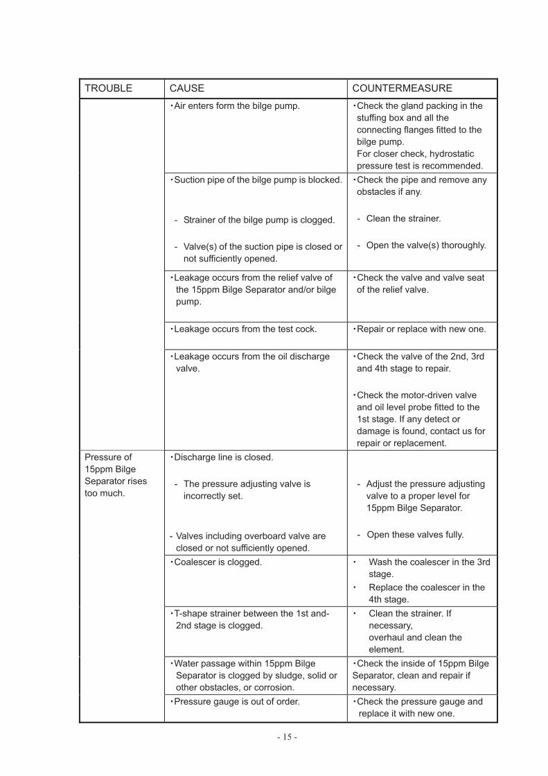
TROUBLE CAUSE COUNTERMEASURE
Air enters form the bilge pump. Check the gland packing in the stuffing box and all the connecting flanges fitted to the bilge pump. For closer check, hydrostatic pressure test is recommended.
Suction pipe of the bilge pump is blocked.
- Strainer of the bilge pump is clogged.
- Valve(s) of the suction pipe is closed or not sufficiently opened.
Check the pipe and remove any obstacles if any.
- Clean the strainer.
- Open the valve(s) thoroughly.
Leakage occurs from the relief valve of the 15ppm Bilge Separator and/or bilge pump.
Check the valve and valve seat of the relief valve.
Leakage occurs from the test cock. Repair or replace with new one.
Leakage occurs from the oil discharge valve.
Check the valve of the 2nd, 3rd and 4th stage to repair.
Check the motor-driven valve and oil level probe fitted to the 1st stage. If any detect or damage is found, contact us for repair or replacement.
Pressure of 15ppm Bilge Separator rises too much.
Discharge line is closed.
- The pressure adjusting valve is incorrectly set.
- Valves including overboard valve are closed or not sufficiently opened.
- Adjust the pressure adjusting valve to a proper level for 15ppm Bilge Separator.
- Open these valves fully.
Coalescer is clogged. Wash the coalescer in the 3rd stage. Replace the coalescer in the 4th stage.
T-shape strainer between the 1st and- 2nd stage is clogged.
Clean the strainer. If necessary, overhaul and clean the element.
Water passage within 15ppm Bilge Separator is clogged by sludge, solid or other obstacles, or corrosion.
Check the inside of 15ppm Bilge Separator, clean and repair if necessary.
Pressure gauge is out of order. Check the pressure gauge and replace it with new one.
- 16 -
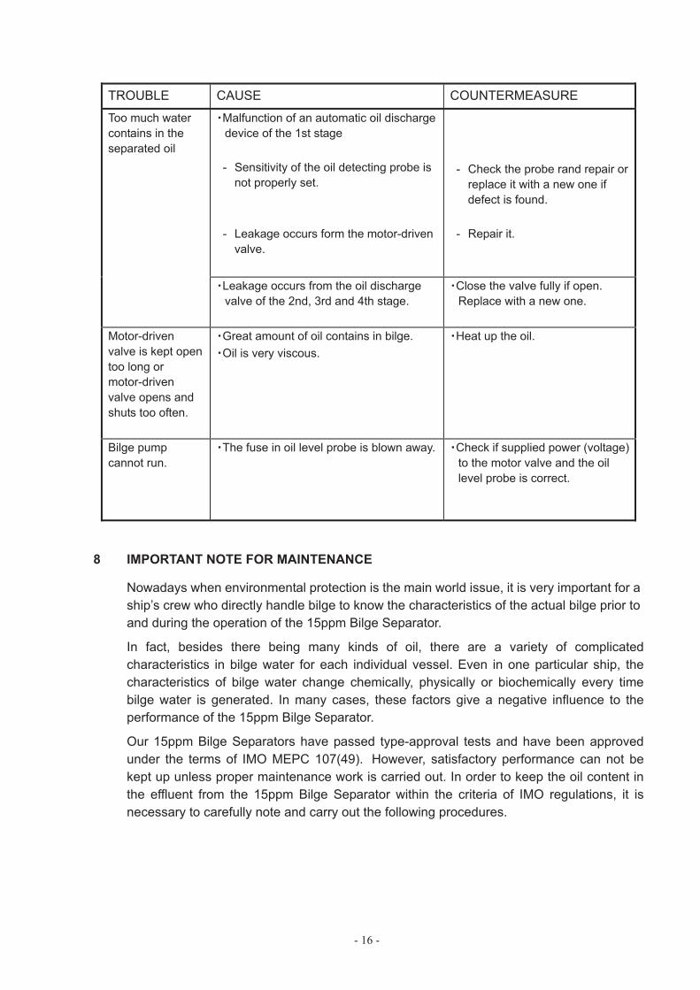
TROUBLE CAUSE COUNTERMEASURE
Too much water contains in the separated oil
Malfunction of an automatic oil dischargedevice of the 1st stage
- Sensitivity of the oil detecting probe is not properly set.
- Leakage occurs form the motor-driven valve.
- Check the probe rand repair orreplace it with a new one if defect is found.
- Repair it.
Leakage occurs from the oil discharge valve of the 2nd, 3rd and 4th stage.
Close the valve fully if open. Replace with a new one.
Motor-drivenvalve is kept open too long or motor-drivenvalve opens and shuts too often.
Great amount of oil contains in bilge. Oil is very viscous.
Heat up the oil.
Bilge pump cannot run.
The fuse in oil level probe is blown away. Check if supplied power (voltage) to the motor valve and the oil level probe is correct.
8 IMPORTANT NOTE FOR MAINTENANCE
Nowadays when environmental protection is the main world issue, it is very important for a ship’s crew who directly handle bilge to know the characteristics of the actual bilge prior to and during the operation of the 15ppm Bilge Separator.
In fact, besides there being many kinds of oil, there are a variety of complicated characteristics in bilge water for each individual vessel. Even in one particular ship, the characteristics of bilge water change chemically, physically or biochemically every time bilge water is generated. In many cases, these factors give a negative influence to the performance of the 15ppm Bilge Separator.
Our 15ppm Bilge Separators have passed type-approval tests and have been approved under the terms of IMO MEPC 107(49). However, satisfactory performance can not be kept up unless proper maintenance work is carried out. In order to keep the oil content in the effluent from the 15ppm Bilge Separator within the criteria of IMO regulations, it is necessary to carefully note and carry out the following procedures.
- 17 -
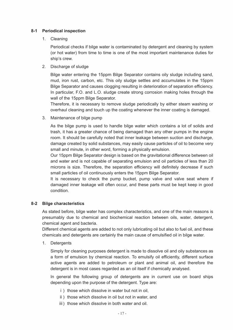
8-1 Periodical inspection
1. Cleaning
Periodical checks if bilge water is contaminated by detergent and cleaning by system (or hot water) from time to time is one of the most important maintenance duties for ship’s crew.
2. Discharge of sludge
Bilge water entering the 15ppm Bilge Separator contains oily sludge including sand, mud, iron rust, carbon, etc. This oily sludge settles and accumulates in the 15ppm Bilge Separator and causes clogging resulting in deterioration of separation efficiency. In particular, F.O. and L.O. sludge create strong corrosion making holes through the wall of the 15ppm Bilge Separator. Therefore, it is necessary to remove sludge periodically by either steam washing or overhaul cleaning and touch up the coating whenever the inner coating is damaged.
3. Maintenance of bilge pump
As the bilge pump is used to handle bilge water which contains a lot of solids and trash, it has a greater chance of being damaged than any other pumps in the engine room. It should be carefully noted that inner leakage between suction and discharge, damage created by solid substances, may easily cause particles of oil to become very small and minute, in other word, forming a physically emulsion. Our 15ppm Bilge Separator design is based on the gravitational difference between oil and water and is not capable of separating emulsion and oil particles of less than 20 microns is size. Therefore, the separation efficiency will definitely decrease if such small particles of oil continuously enters the 15ppm Bilge Separator. It is necessary to check the pump bucket, pump valve and valve seat where if damaged inner leakage will often occur, and these parts must be kept keep in good condition.
8-2 Bilge characteristics
As stated before, bilge water has complex characteristics, and one of the main reasons is presumably due to chemical and biochemical reaction between oils, water, detergent, chemical agent and bacteria. Different chemical agents are added to not only lubricating oil but also to fuel oil, and these chemicals and detergents are certainly the main cause of emulsified oil in bilge water.
1. Detergents
Simply for cleaning purposes detergent is made to dissolve oil and oily substances as a form of emulsion by chemical reaction. To emulsify oil efficiently, different surface active agents are added to petroleum or plant and animal oil, and therefore the detergent is in most cases regarded as an oil itself if chemically analysed.
In general the following group of detergents are in current use on board ships depending upon the purpose of the detergent. Type are:
) those which dissolve in water but not in oil, ) those which dissolve in oil but not in water, and ) those which dissolve in both water and oil.
- 18 -
Without exception, all detergents in the market react against oil to make it chemically emulsified when mixed with water. The size of an oil particle in a chemical emulsion is far less than 1 micron and will not float at all. For the above reason, in general detergent has a substantial influence on the 15ppm Bilge Separator.
Physical separation method based on the gravitational difference between oil and water is not capable of separating particles of oil of less than 20 microns in size for light oil and 10 microns for heavy oil. Chemically emulsified oil makes maintenance term of coalescer in the 3rd and 4th stage shorten due to burden enlargement of the coalescers for emulsion separation.
Therefore, it is very important to avoid mixing any detergent into bilge as less as possible.
2. Anti-corrosive oil for engine cooling water
Some brands of anticorrosive agent (soluble oil type) have exactly the same characteristics and ingredients as the above detergent, which is chemically emulsified when it is dissolved in water.
Therefore, it is recommended not to mix this soluble oil type of anticorrosive oil into the bilge.
3. Compressor drain
Although drain fluid discharged from air compressors is very small in quantity, this drain fluid is in most cases emulsified which may cause a negative effect on the 15ppm Bilge Separator.
Attention should be paid to the quantity of compressor drain fluid and proper countermeasures are necessary if the quantity increases for any reason.
4. Sludge
Sludge is equally as bad a factor on 15ppm Bilge Separator performance as detergent when it enters the 15ppm Bilge Separator in any great amount. In any case, it is strongly recommended that mixing sludge into bilge water should be minimised.
- 19 -
9 OTHER FACTOR FOR SEPARATION EFFICIENCY
9-1 Condition of bilge water
In general, bilge water in the bilge tank forms into the following group of layers.
1. Top layer (0n the surface) : floating oil 2. Middle layer : small and minute particle of oil including emulsion 3. Bottom layer : settled solids and sludge
The separation performance of the 15ppm Bilge Separator is adversely influenced by the oil staying in the middle layer. Due to the ship’s pitching and rolling, rather big particles of oil can adhere to and combine with suspended solids (SS) forming oily solids whilst dissolved detergent makes a small oil droplet even smaller, or emulsified, due to frequent contact created by motion of ship, and maintenance term of coalescers in 3rd and 4th stage become shorter and shorter accordingly.
Therefore the 15ppm Bilge Separator should not be operated in such rough weather conditions which may help to mix up oil, water and sludge layers.
9-2 Kind of oil
Regardless of the conditions, a 15ppm Bilge Separator must separate oil from bilge water to a level of where the oil content becomes less than 15 ppm in the effluent. Therefore, 15ppm Bilge Separator should play an important role to reduce oil pollution. Our 15ppm Bilge Separator has been designed and constructed to handle bilge water without any problems based on our long experience. In general the separation performance varies depending upon the type of oil in the bilge water. The lighter the oil becomes, the more difficult becomes the separation of oil from water.
In other words, oil of a small relative density and low viscosity is difficult for the 15ppm Bilge Separator to handle. Also the higher the pressure of the bilge pump becomes, the greater the quantity of smaller oil particles resulting in poor separation efficiency.
* * * * * * * *
CLEANING OF COALESCER
Under the condition where an oily water separator is used for a long time, a coalescer installed in the 3rd
chamber (stage) is gradually getting dirty to make separation performance less by clogging the coalescer. The clog of the coalescer mainly happens when the separator is supplied the bilge containing much sludge and/or suspended solid, and big amount of oil floating the surface of the bilge. In case that the coalescer is clogged, differential pressure between 2nd and 3rd chambers (stages) becomes bigger and bigger. In general, it is recommended to clean the coalescer with steam or hot water when the differential pressure goes up to 0.07-0.1 MPa except the differential pressure comes from clog of a T-shape strainer fitted on the connection pipe between 2nd and 3rd chambers (stages). If the strainer is clogged, the strainer is cleaned by handle fitted on top of the strainer. In either case, cleaning work is carried on in accordance with operation manual. In condition where the coalescer is heavily clogged (the differential pressure goes up to about 0.1 MPa.), it is requested to take out the coalscer from the separator in the following manner for cleaning purpose.
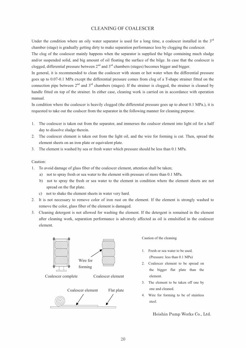
1. The coalescer is taken out from the separator, and immerses the coalscer element into light oil for a half day to dissolve sludge therein.
2. The coalescer element is taken out from the light oil, and the wire for forming is cut. Then, spread the element sheets on an iron plate or equivalent plate.
3. The element is washed by sea or fresh water which pressure should be less than 0.1 MPa.
Caution: 1. To avoid damage of glass fiber of the coalescer element, attention shall be taken; a) not to spray fresh or sea water to the element with pressure of more than 0.1 MPa.
b) not to spray the fresh or sea water to the element in condition where the element sheets are not spread on the flat plate.
c) not to shake the element sheets in water very hard. 2. It is not necessary to remove color of iron rust on the element. If the element is strongly washed to
remove the color, glass fiber of the element is damaged. 3. Cleaning detergent is not allowed for washing the element. If the detergent is remained in the element
after cleaning work, separation performance is adversely affected as oil is emulsified in the coalescer element.
Heishin Pump Works Co., Ltd.
Caution of the cleaning
1. Fresh or sea water to be used.
(Pressure: less than 0.1 MPa)
2. Coalescer element to be spread on
the bigger flat plate than the
element.
3. The element to be taken off one by
one and cleaned.
4. Wire for forming to be of stainless
steel.
Wire for forming
Coalescer complete Coalescer element
Flat plate Coalescer element
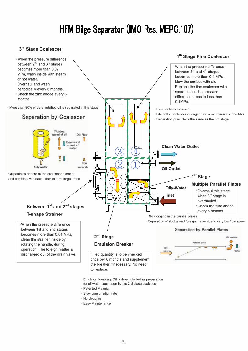
3rd Stage Coalescer
・No clogging in the parallel plates ・Separation of sludge and foreign matter due to very low flow speed
Overhaul this stage when 3rd stage is overhauled. Check the zinc anode every 6 months
Oil Outlet
1st Stage Multiple Parallel Plates
2nd Stage Emulsion Breaker
①②③ ④
When the pressure difference between 2nd and 3rd stages becomes more than 0.07 MPa, wash inside with steam or hot water. Overhaul and wash periodically every 6 months. Check the zinc anode every 6 months
・More than 90% of de-emulsified oil is separated in this stage
Between 1st and 2nd stages T-shape Strainer
Oil particles adhere to the coalescer element and combine with each other to form large drops
Filled quantity is to be checked once per 6 months and supplement the breaker if necessary. No need to replace.
When the pressure difference between 1st and 2nd stages becomes more than 0.04 MPa, clean the strainer inside by rotating the handle, during operation. The foreign matter is discharged out of the drain valve.
Clean Water Outlet
When the pressure difference between 3rd and 4th stages becomes more than 0.1 MPa, blow the surface with air. Replace the fine coalescer with spare unless the pressure difference drops to less than 0.1MPa.
・Fine coalescer is used ・Life of the coalescer is longer than a membrane or fine filter ・Separation principle is the same as the 3rd stage
Oily-Water
Inlet
4th Stage Fine Coalescer
・Emulsion breaking: Oil is de-emulsified as preparation for oil/water separation by the 3rd stage coalescer ・Patented Material ・Slow consumption rate ・No clogging ・Easy Maintenance
Head Office Factory
HEISHIN PUMP WORKS CO., LTD.
675-0146 1-5-30, Furuta, Harima-cho, Kako-gun,
1-5-30 Hyogo Pref, Japan 675-0146
Tel. 079-436-3018 Tel. +81-79-436-3018
Fax. 079-436-4501 Fax. +81-79-436-4501
Sales Agent
All information in this manual is subject to change without prior notice.