Embed Size (px)
Citation preview
Page 1
HH Technology Corp.
New Alkoxylation Technologies
Alcoxilação � Il Seminário Interno May 9, 2000 Sao Paulo, Brazil
By
Urs Geser & Rich Malone
HH Technology Corp. NOTICE: This article is under HHTC�s copyrights and shall not be copied or duplicated or used or
disclosed - in whole or in part � for any purpose without HHTC�s prior written approval.
Page 2
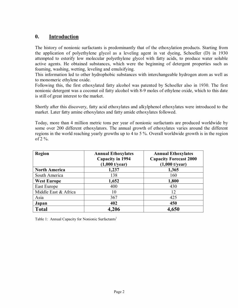
0. Introduction The history of nonionic surfactants is predominantly that of the ethoxylation products. Starting from the application of polyethylene glycol as a leveling agent in vat dyeing, Schoeller (D) in 1930 attempted to esterify low molecular polyethylene glycol with fatty acids, to produce water soluble active agents. He obtained substances, which were the beginning of detergent properties such as foaming, washing, wetting, leveling and emulsifying. This information led to other hydrophobic substances with interchangeable hydrogen atom as well as to monomeric ethylene oxide. Following this, the first ethoxylated fatty alcohol was patented by Schoeller also in 1930. The first nonionic detergent was a coconut oil fatty alcohol with 8-9 moles of ethylene oxide, which to this date is still of great interest to the market. Shortly after this discovery, fatty acid ethoxylates and alkylphenol ethoxylates were introduced to the market. Later fatty amine ethoxylates and fatty amide ethoxylates followed. Today, more than 4 million metric tons per year of nonionic surfactants are produced worldwide by some over 200 different ethoxylators. The annual growth of ethoxylates varies around the different regions in the world reaching yearly growths up to 4 to 5 %. Overall worldwide growth is in the region of 2 %. Region Annual Ethoxylates
Capacity in 1994 (1,000 t/year)
Annual Ethoxylates Capacity Forecast 2000
(1,000 t/year) North America 1,237 1,365 South America 138 160 West Europe 1,652 1,800 East Europe 400 430 Middle East & Africa 10 12 Asia 367 425 Japan 402 450 Total 4,206 4,650 Table 1: Annual Capacity for Nonionic Surfactants1
Page 3
Over the last few years, ethoxylation has become a very high cost competitive process to add hydrophilic character to a wide variety of hydrophobic feedstocks. As a result of this, plant efficiency has been improved by:
• higher performance plants (better mixing reactors) • lower utility requirements • better reactor volume utilization • better material flow through the facility
Page 4
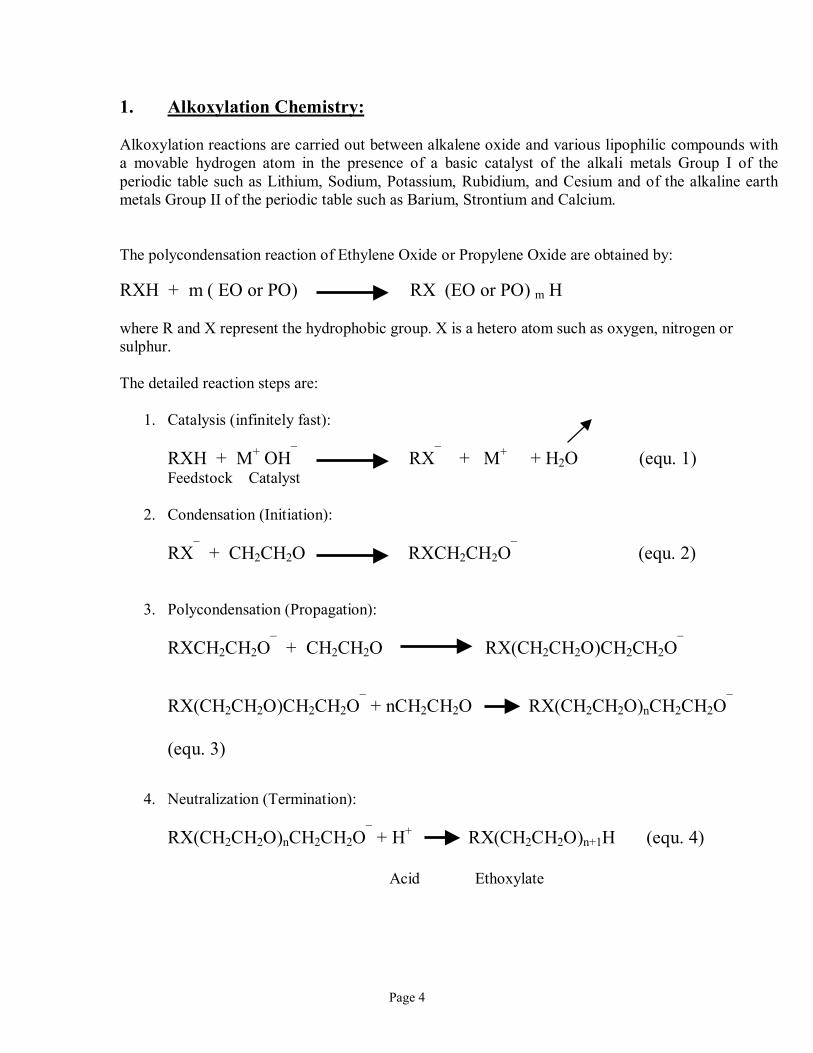
1. Alkoxylation Chemistry: Alkoxylation reactions are carried out between alkalene oxide and various lipophilic compounds with a movable hydrogen atom in the presence of a basic catalyst of the alkali metals Group I of the periodic table such as Lithium, Sodium, Potassium, Rubidium, and Cesium and of the alkaline earth metals Group II of the periodic table such as Barium, Strontium and Calcium. The polycondensation reaction of Ethylene Oxide or Propylene Oxide are obtained by: RXH + m ( EO or PO) RX (EO or PO) m H where R and X represent the hydrophobic group. X is a hetero atom such as oxygen, nitrogen or sulphur. The detailed reaction steps are:
1. Catalysis (infinitely fast):
RXH + M+ OH¯ RX¯ + M+ + H2O (equ. 1) Feedstock Catalyst
2. Condensation (Initiation):
RX¯ + CH2CH2O RXCH2CH2O¯ (equ. 2)
3. Polycondensation (Propagation):
RXCH2CH2O¯ + CH2CH2O RX(CH2CH2O)CH2CH2O¯
RX(CH2CH2O)CH2CH2O¯ + nCH2CH2O RX(CH2CH2O)nCH2CH2O¯
(equ. 3)
4. Neutralization (Termination):
RX(CH2CH2O)nCH2CH2O¯ + H+ RX(CH2CH2O)n+1H (equ. 4) Acid Ethoxylate
Page 5
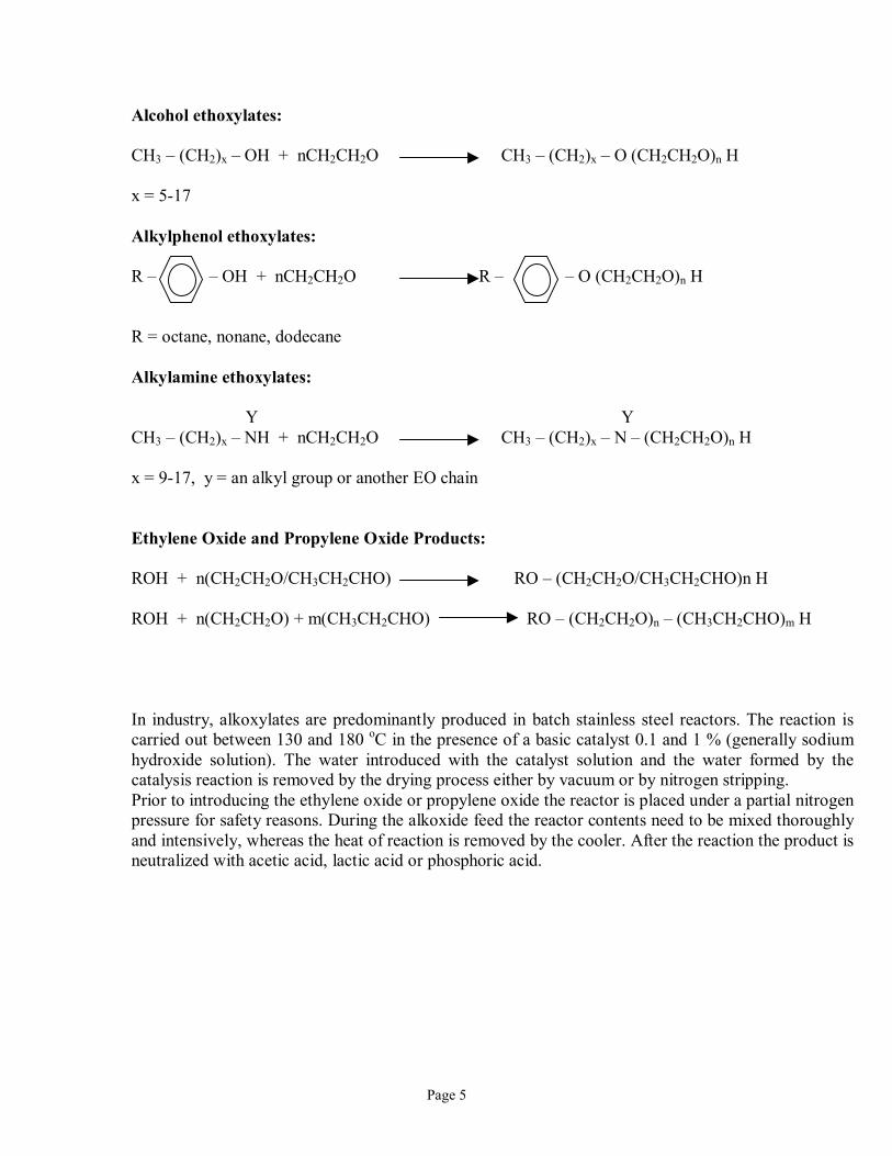
Alcohol ethoxylates: CH3 � (CH2)x � OH + nCH2CH2O CH3 � (CH2)x � O (CH2CH2O)n H x = 5-17 Alkylphenol ethoxylates: R � � OH + nCH2CH2O R � � O (CH2CH2O)n H R = octane, nonane, dodecane Alkylamine ethoxylates: Y Y CH3 � (CH2)x � NH + nCH2CH2O CH3 � (CH2)x � N � (CH2CH2O)n H x = 9-17, y = an alkyl group or another EO chain Ethylene Oxide and Propylene Oxide Products: ROH + n(CH2CH2O/CH3CH2CHO) RO � (CH2CH2O/CH3CH2CHO)n H ROH + n(CH2CH2O) + m(CH3CH2CHO) RO � (CH2CH2O)n � (CH3CH2CHO)m H In industry, alkoxylates are predominantly produced in batch stainless steel reactors. The reaction is carried out between 130 and 180 oC in the presence of a basic catalyst 0.1 and 1 % (generally sodium hydroxide solution). The water introduced with the catalyst solution and the water formed by the catalysis reaction is removed by the drying process either by vacuum or by nitrogen stripping. Prior to introducing the ethylene oxide or propylene oxide the reactor is placed under a partial nitrogen pressure for safety reasons. During the alkoxide feed the reactor contents need to be mixed thoroughly and intensively, whereas the heat of reaction is removed by the cooler. After the reaction the product is neutralized with acetic acid, lactic acid or phosphoric acid.
Page 6
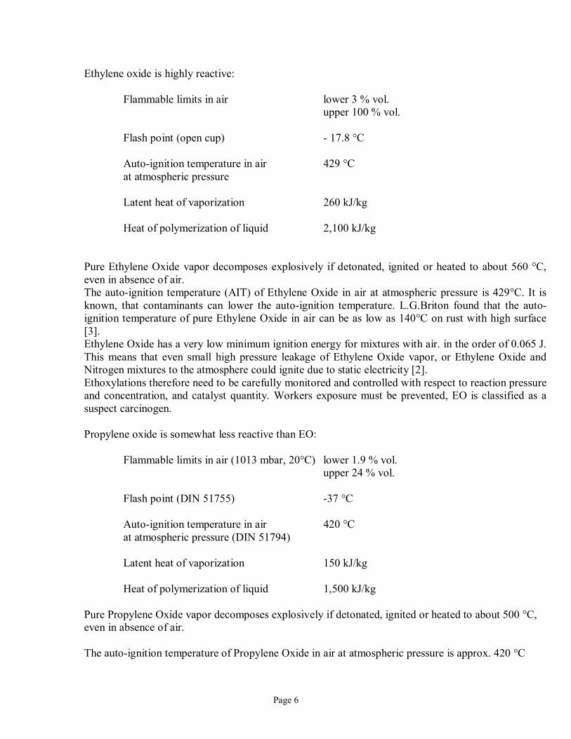
Ethylene oxide is highly reactive:
Flammable limits in air lower 3 % vol. upper 100 % vol. Flash point (open cup) - 17.8 °C Auto-ignition temperature in air 429 °C at atmospheric pressure Latent heat of vaporization 260 kJ/kg Heat of polymerization of liquid 2,100 kJ/kg
Pure Ethylene Oxide vapor decomposes explosively if detonated, ignited or heated to about 560 °C, even in absence of air. The auto-ignition temperature (AIT) of Ethylene Oxide in air at atmospheric pressure is 429°C. It is known, that contaminants can lower the auto-ignition temperature. L.G.Briton found that the auto-ignition temperature of pure Ethylene Oxide in air can be as low as 140°C on rust with high surface [3]. Ethylene Oxide has a very low minimum ignition energy for mixtures with air. in the order of 0.065 J. This means that even small high pressure leakage of Ethylene Oxide vapor, or Ethylene Oxide and Nitrogen mixtures to the atmosphere could ignite due to static electricity [2]. Ethoxylations therefore need to be carefully monitored and controlled with respect to reaction pressure and concentration, and catalyst quantity. Workers exposure must be prevented, EO is classified as a suspect carcinogen. Propylene oxide is somewhat less reactive than EO:
Flammable limits in air (1013 mbar, 20°C) lower 1.9 % vol. upper 24 % vol. Flash point (DIN 51755) -37 °C Auto-ignition temperature in air 420 °C at atmospheric pressure (DIN 51794) Latent heat of vaporization 150 kJ/kg Heat of polymerization of liquid 1,500 kJ/kg
Pure Propylene Oxide vapor decomposes explosively if detonated, ignited or heated to about 500 °C, even in absence of air. The auto-ignition temperature of Propylene Oxide in air at atmospheric pressure is approx. 420 °C
Page 7
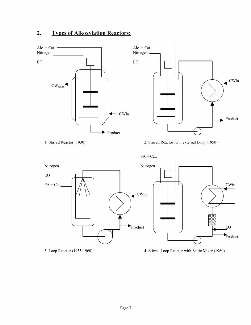
2. Types of Alkoxylation Reactors: Alc. + Cat. Alc. + Cat. Nitrogen Nitrogen EO EO CWin CWreturn CWin Product Product
1. Stirred Reactor (1930) 2. Stirred Reactor with external Loop (1950) FA + Cat. Nitrogen Nitrogen EO FA + Cat. CWin
CWin Product EO Product 3. Loop Reactor (1955-1960) 4. Stirred Loop Reactor with Static Mixer (1960)
Page 8
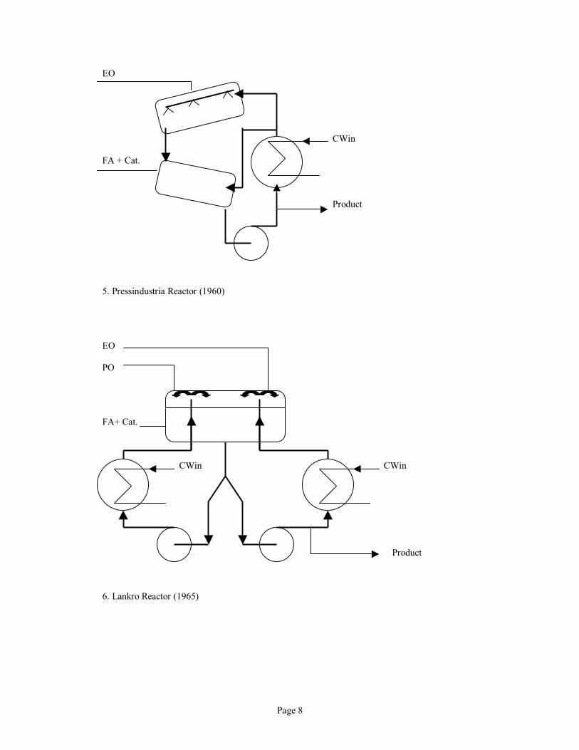
EO CWin FA + Cat. Product 5. Pressindustria Reactor (1960) EO PO FA+ Cat.
CWin CWin Product 6. Lankro Reactor (1965)
Page 9
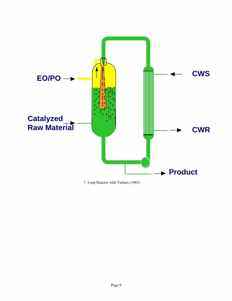
7. Loop Reactor with Venturi (1985)
Product
EO/PO
Catalyzed Raw Material
CWS
CWR
Pa
ge 1
0
Rea
ctor
Typ
e Pr
essu
re
desi
gn
(psi
)
Feed
ing
Gas
M
ovem
ent
in
Rea
ctor
�s
Hea
dspa
ce
Igni
tion
sour
ces
EO
or
PO
Feed
ing
Poin
t In
erts
V
isco
sity
H
eat R
emov
al
Res
idua
l EO
af
ter
20 m
inut
es
1. S
tirre
d R
eact
or
75 to
150
20
0 �
300
Ver
y lo
w
Yes
, mec
hani
cal
stirr
er, p
oor g
as
mov
emen
t
Dip
tube
, ris
k of
ba
ckflo
w
No
Low
to h
igh
visc
ositi
es,
5,00
0 to
20,
000
Ver
y lo
w U
-co
effic
ient
, lim
ited
heat
rem
oval
< 10
� 2
0 pp
m
2. S
tirre
d R
eact
or
with
ext
erna
l lo
op
75 to
150
40
0 V
ery
low
Y
es, m
echa
nica
l st
irrer
, poo
r gas
m
ovem
ent
Dip
tube
, ris
k of
ba
ckflo
w
No
Low
to m
ediu
m
visc
ositi
es
1,00
0
Bette
r hea
t re
mov
al c
apac
ity
< 10
� 2
0 pp
m
3. L
oop
Rea
ctor
75
to 1
50
800
Goo
d Y
es, p
oten
tially
fr
om
inho
mog
eneo
us
gas d
istri
butio
n an
d EO
feed
ing
proc
edur
e (h
ot
spot
s)
Dip
tube
, ris
k of
ba
ckflo
w
Yes
, but
no
t out
side
ex
plos
ion
limits
Low
vis
cosi
ties
500
Goo
d he
at re
mov
al
capa
city
<
5 �
10 p
pm
4. S
tirre
d Lo
op
Rea
ctor
with
St
atic
Mix
er
75 to
1
50
400
Ver
y lo
w
Yes
, mec
hani
cal
stirr
er, p
oor g
as
mov
emen
t
Fed
into
loop
, ris
k of
bac
kflo
w
No
Low
to m
ediu
m
visc
ositi
es
1,00
0
Goo
d he
at re
mov
al
capa
city
<
10 �
20
ppm
5. P
ress
indu
stria
R
eact
or
75 to
150
80
0 G
ood
Yes
, pot
entia
lly
from
in
hom
ogen
eous
ga
s dis
tribu
tion
and
EO fe
edin
g pr
oced
ure
(hot
sp
ots)
Fed
into
gas
sp
ace
No
Low
to m
ediu
m
visc
ositi
es
1,00
0
Goo
d he
at re
mov
al
capa
city
<
5 �
7 p
pm E
O
6. L
ankr
o R
eact
or
75 to
150
40
0-60
0 G
ood
Yes
, pot
entia
lly
from
in
hom
ogen
eous
ga
s dis
tribu
tion
and
EO fe
edin
g pr
oced
ure
(hot
sp
ots)
Fed
into
gas
sp
ace
No
Low
vis
cosi
ties
500
Goo
d he
at re
mov
al
capa
city
<
7 �
10
ppm
7. H
H L
oop
Rea
ctor
65
0 10
00-1
500
Ver
y hi
gh
Min
imal
, ver
y ho
mog
eneo
us g
as
distr
ibut
ion
Fed
into
gas
sp
ace
Yes
, ou
tsid
e ex
plos
ion
limit
Low
vis
cosi
ties
500
Hig
h U
-co
effic
ient
, ver
y hi
gh h
eat r
emov
al
capa
city
< 1
ppm

Pa
ge 1
1
Page 12
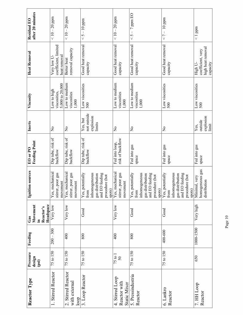
In general it is to be noted that all loop type of reactors achieve higher productivity in the range of 6 to 8 batches per day versus 3 to 5 batches per day for conventional stirred reactors. Further, it is to be noted that most reactors except the HH Loop Reactor operate during the start of the reaction within the explosive limits of Ethylene Oxide. Even though some nitrogen is added to the various reactors, they are not sufficiently pressurized with nitrogen because the reaction would be slowed down by the nitrogen content and the poor gas/liquid mixing in the reactor headspace. After closing the Ethylene Oxide feed at the end of an ethoxylation, for all conventional reactors the reacting down of ethylene oxide is slow compared to the better mixing loop reactors. The products in conventional reactors contain high residual ethylene oxide, dioxane content and have poor color. Thus, for conventional reactors the final treatment is more work intensive to strip out these residual components with nitrogen and steam. Further, depending on the surfactant application it may require to bleach the product, which generally is achieved with hydrogen peroxide.
Page 13
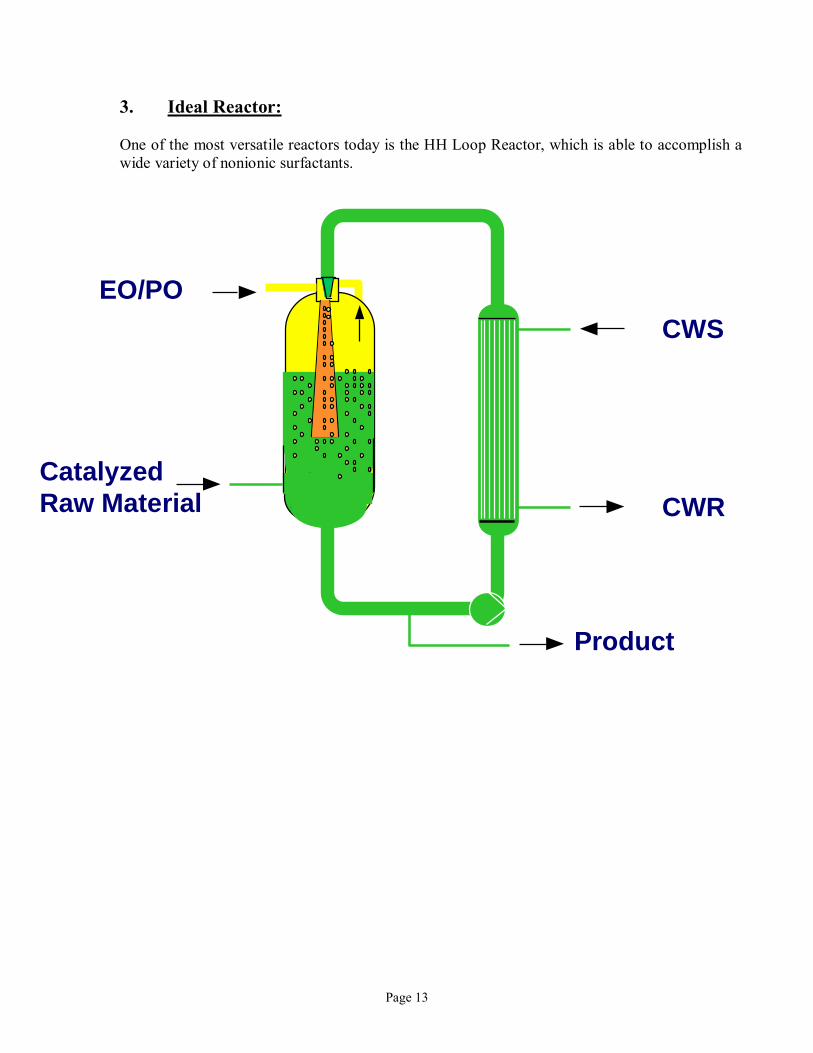
3. Ideal Reactor: One of the most versatile reactors today is the HH Loop Reactor, which is able to accomplish a wide variety of nonionic surfactants.
Product
EO/PO
Catalyzed Raw Material
CWS
CWR
Page 14
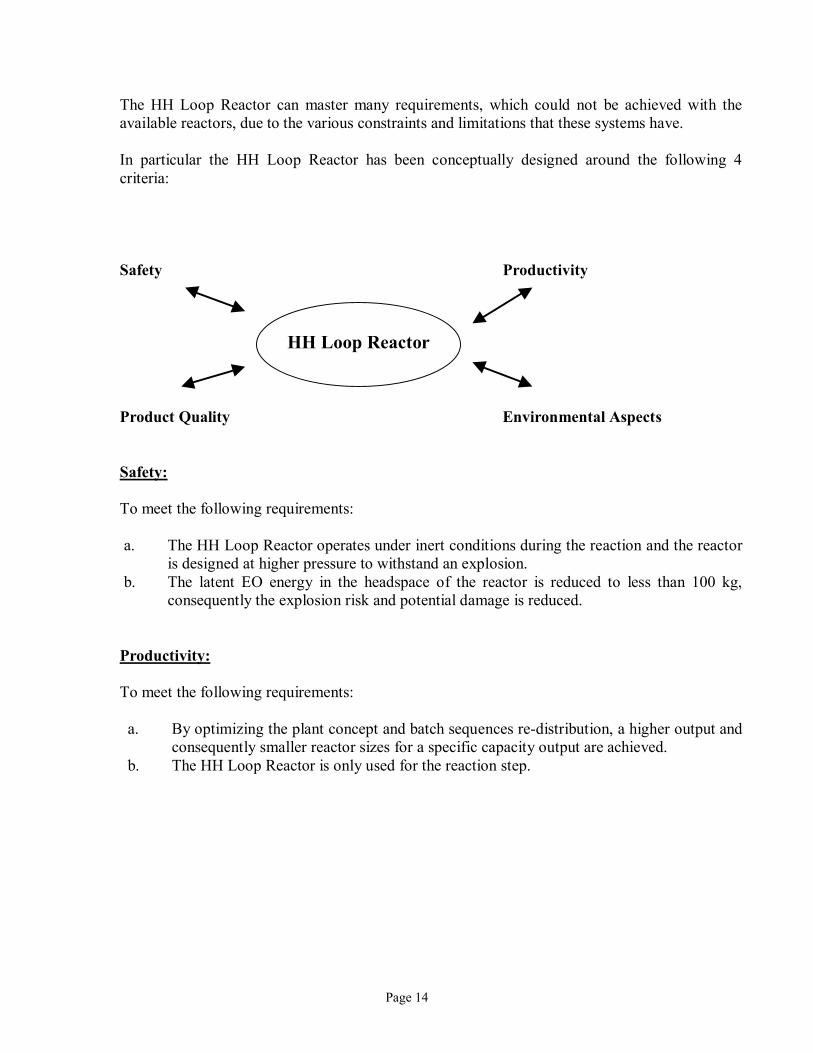
The HH Loop Reactor can master many requirements, which could not be achieved with the available reactors, due to the various constraints and limitations that these systems have. In particular the HH Loop Reactor has been conceptually designed around the following 4 criteria: Safety Productivity HH Loop Reactor Product Quality Environmental Aspects Safety: To meet the following requirements: a. The HH Loop Reactor operates under inert conditions during the reaction and the reactor
is designed at higher pressure to withstand an explosion. b. The latent EO energy in the headspace of the reactor is reduced to less than 100 kg,
consequently the explosion risk and potential damage is reduced. Productivity: To meet the following requirements: a. By optimizing the plant concept and batch sequences re-distribution, a higher output and
consequently smaller reactor sizes for a specific capacity output are achieved. b. The HH Loop Reactor is only used for the reaction step.
Page 15
Product Quality: To meet the following requirements: a. The HH Loop Reactor allows production of ethoxylates below 1 ppm residual EO in the
liquid phase and propoxylates below 50 ppm residual PO in the liquid phase. In the case of plants producing ethoxylates only,several plants have been built without any scrubbing system.
Environmental Aspects: To meet the following requirements: a. Reduction of dioxane and other side products (eg. dioxalanes, PEGs) due to the high
mass transfer rates and consequently fast reaction kinetics achieved by the Jet Mixer.
b. The HH Loop Reactor is operated as a closed system, vent operations are primarily limited to washing sequences, which follow incompatible product changes.
Page 16
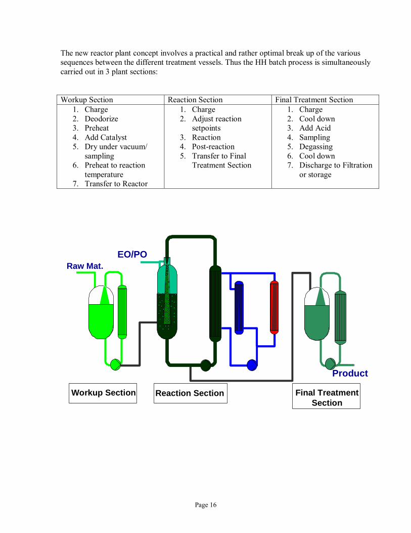
The new reactor plant concept involves a practical and rather optimal break up of the various sequences between the different treatment vessels. Thus the HH batch process is simultaneously carried out in 3 plant sections: Workup Section Reaction Section Final Treatment Section
1. Charge 2. Deodorize 3. Preheat 4. Add Catalyst 5. Dry under vacuum/
sampling 6. Preheat to reaction
temperature 7. Transfer to Reactor
1. Charge 2. Adjust reaction
setpoints 3. Reaction 4. Post-reaction 5. Transfer to Final
Treatment Section
1. Charge 2. Cool down 3. Add Acid 4. Sampling 5. Degassing 6. Cool down 7. Discharge to Filtration
or storage
Reaction Section Final TreatmentSection
Workup Section
Raw Mat.
Product
EO/PO
Page 17
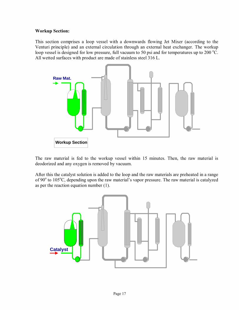
Workup Section: This section comprises a loop vessel with a downwards flowing Jet Mixer (according to the Venturi principle) and an external circulation through an external heat exchanger. The workup loop vessel is designed for low pressure, full vacuum to 50 psi and for temperatures up to 200 oC. All wetted surfaces with product are made of stainless steel 316 L.
The raw material is fed to the workup vessel within 15 minutes. Then, the raw material is deodorized and any oxygen is removed by vacuum. After this the catalyst solution is added to the loop and the raw materials are preheated in a range of 90o to 105oC, depending upon the raw material�s vapor pressure. The raw material is catalyzed as per the reaction equation number (1).
Workup Section
Raw Mat.
Catalyst
Page 18
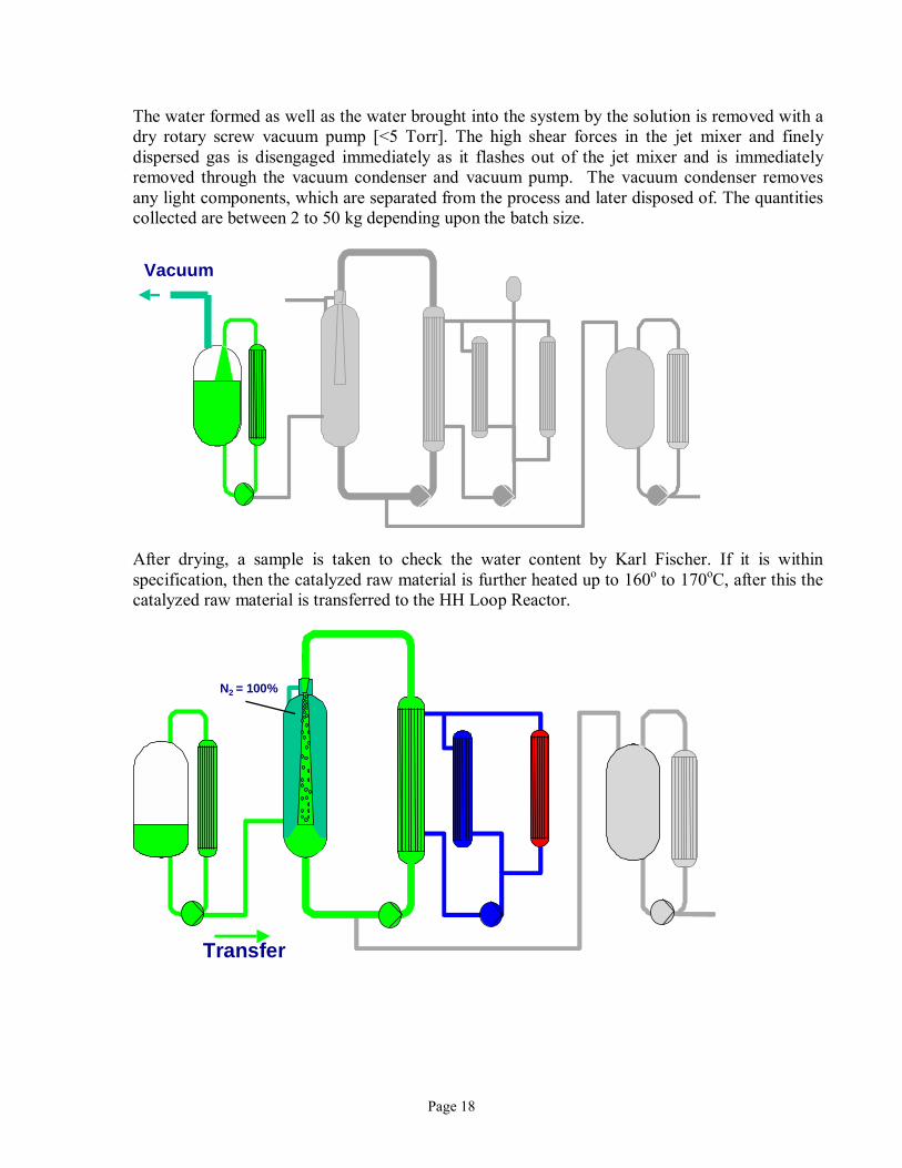
The water formed as well as the water brought into the system by the solution is removed with a dry rotary screw vacuum pump [<5 Torr]. The high shear forces in the jet mixer and finely dispersed gas is disengaged immediately as it flashes out of the jet mixer and is immediately removed through the vacuum condenser and vacuum pump. The vacuum condenser removes any light components, which are separated from the process and later disposed of. The quantities collected are between 2 to 50 kg depending upon the batch size.
After drying, a sample is taken to check the water content by Karl Fischer. If it is within specification, then the catalyzed raw material is further heated up to 160o to 170oC, after this the catalyzed raw material is transferred to the HH Loop Reactor.
Vacuum
Transfer
N2 = 100%
Page 19
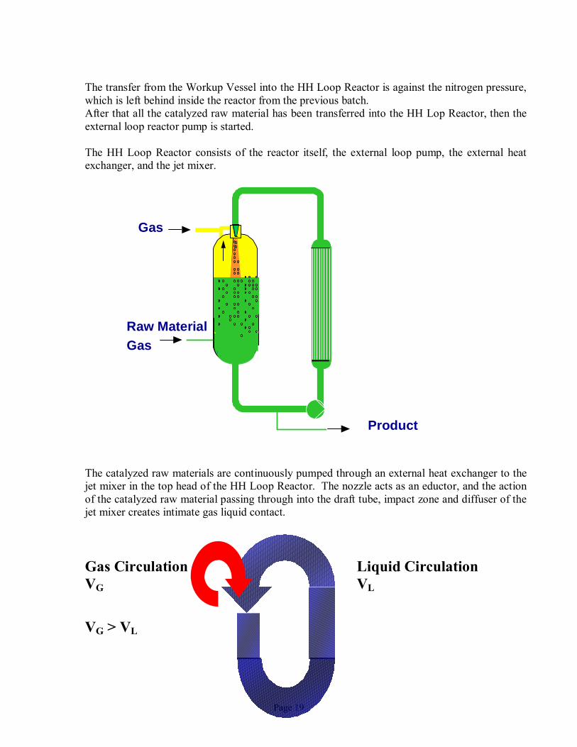
The transfer from the Workup Vessel into the HH Loop Reactor is against the nitrogen pressure, which is left behind inside the reactor from the previous batch. After that all the catalyzed raw material has been transferred into the HH Lop Reactor, then the external loop reactor pump is started. The HH Loop Reactor consists of the reactor itself, the external loop pump, the external heat exchanger, and the jet mixer.
The catalyzed raw materials are continuously pumped through an external heat exchanger to the jet mixer in the top head of the HH Loop Reactor. The nozzle acts as an eductor, and the action of the catalyzed raw material passing through into the draft tube, impact zone and diffuser of the jet mixer creates intimate gas liquid contact. Gas Circulation Liquid Circulation VG VL VG > VL
Gas
Raw MaterialGas
Product
Page 20
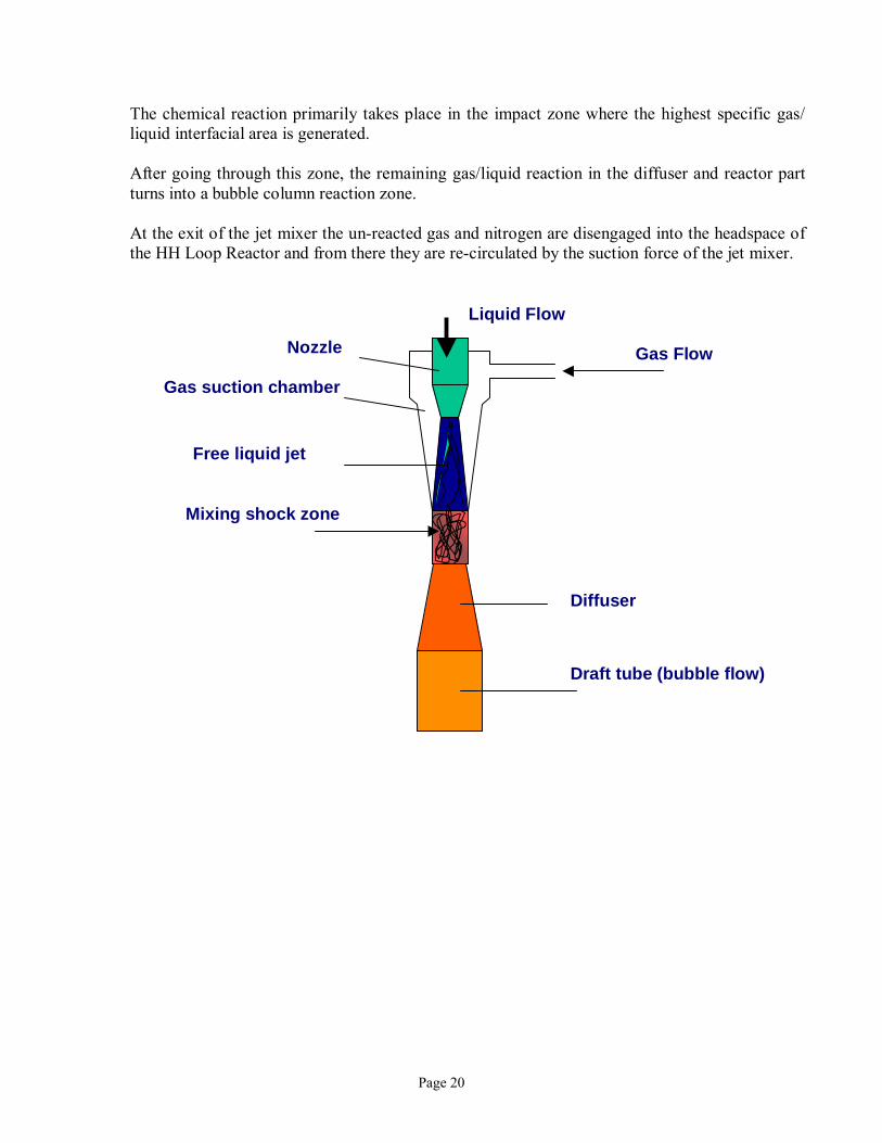
The chemical reaction primarily takes place in the impact zone where the highest specific gas/ liquid interfacial area is generated. After going through this zone, the remaining gas/liquid reaction in the diffuser and reactor part turns into a bubble column reaction zone. At the exit of the jet mixer the un-reacted gas and nitrogen are disengaged into the headspace of the HH Loop Reactor and from there they are re-circulated by the suction force of the jet mixer.
Gas Flow
Liquid Flow
Nozzle
Gas suction chamber
Free liquid jet
Mixing shock zone
Draft tube (bubble flow)
Diffuser
Page 21
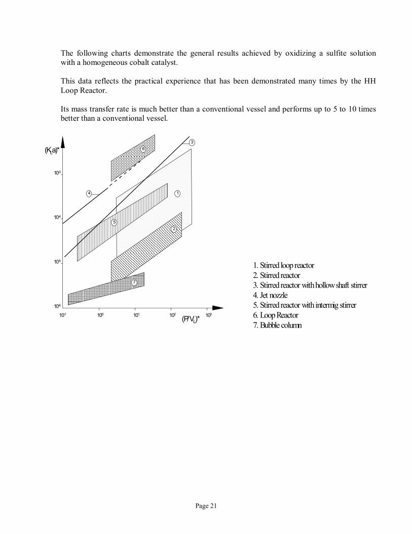
The following charts demonstrate the general results achieved by oxidizing a sulfite solution with a homogeneous cobalt catalyst. This data reflects the practical experience that has been demonstrated many times by the HH Loop Reactor. Its mass transfer rate is much better than a conventional vessel and performs up to 5 to 10 times better than a conventional vessel.
10310210110010-1
10-6
10-5
10-4
10-3
(KLa)*
(P/VL)*
1
25
63
4
7
1. Stirred loop reactor 2. Stirred reactor 3. Stirred reactor with hollow shaft stirrer 4. Jet nozzle 5. Stirred reactor with intermig stirrer 6. Loop Reactor 7. Bubble column
Page 22
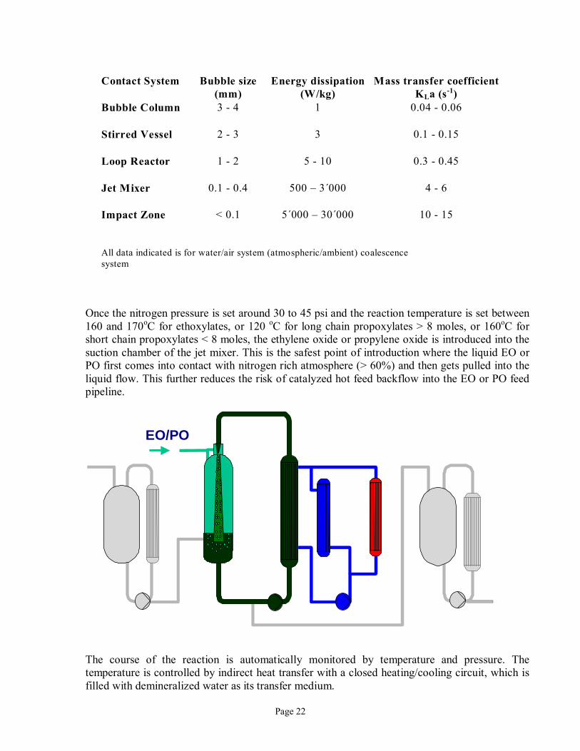
Once the nitrogen pressure is set around 30 to 45 psi and the reaction temperature is set between 160 and 170oC for ethoxylates, or 120 oC for long chain propoxylates > 8 moles, or 160oC for short chain propoxylates < 8 moles, the ethylene oxide or propylene oxide is introduced into the suction chamber of the jet mixer. This is the safest point of introduction where the liquid EO or PO first comes into contact with nitrogen rich atmosphere (> 60%) and then gets pulled into the liquid flow. This further reduces the risk of catalyzed hot feed backflow into the EO or PO feed pipeline.
The course of the reaction is automatically monitored by temperature and pressure. The temperature is controlled by indirect heat transfer with a closed heating/cooling circuit, which is filled with demineralized water as its transfer medium.
Contact System Bubble size (mm)
Energy dissipation(W/kg)
Mass transfer coefficientKLa (s-1)
Bubble Column
3 - 4 1 0.04 - 0.06
Stirred Vessel
2 - 3 3 0.1 - 0.15
Loop Reactor
1 - 2 5 - 10 0.3 - 0.45
Jet Mixer
0.1 - 0.4 500 � 3´000 4 - 6
Impact Zone
< 0.1 5´000 � 30´000 10 - 15
All data indicated is for water/air system (atmospheric/ambient) coalescence system
EO/PO
Page 23
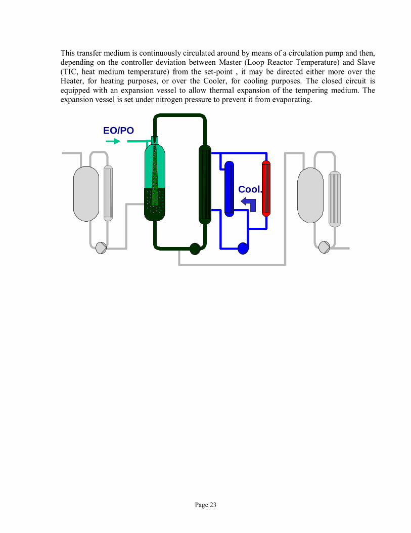
This transfer medium is continuously circulated around by means of a circulation pump and then, depending on the controller deviation between Master (Loop Reactor Temperature) and Slave (TIC, heat medium temperature) from the set-point , it may be directed either more over the Heater, for heating purposes, or over the Cooler, for cooling purposes. The closed circuit is equipped with an expansion vessel to allow thermal expansion of the tempering medium. The expansion vessel is set under nitrogen pressure to prevent it from evaporating.
EO/PO
Cool.
Page 24
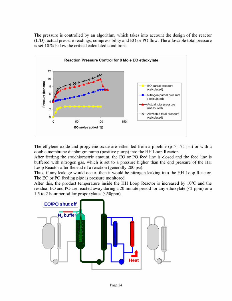
The pressure is controlled by an algorithm, which takes into account the design of the reactor (L/D), actual pressure readings, compressibility and EO or PO flow. The allowable total pressure is set 10 % below the critical calculated conditions.
Reaction Pressure Control for 8 Mole EO ethoxylate
0
2
4
6
8
10
12
0 50 100 150
EO moles added (%)
Pres
sure
(bar
atm
)
EO partial pressure(calculated)
Nitrogen partial pressure( calculated)
Actual total pressure(measured)
Allowable total pressure(calculated)
The ethylene oxide and propylene oxide are either fed from a pipeline (p > 175 psi) or with a double membrane diaphragm pump (positive pump) into the HH Loop Reactor. After feeding the stoichiometric amount, the EO or PO feed line is closed and the feed line is buffered with nitrogen gas, which is set to a pressure higher than the end pressure of the HH Loop Reactor after the end of a reaction (generally 200 psi). Thus, if any leakage would occur, then it would be nitrogen leaking into the HH Loop Reactor. The EO or PO feeding pipe is pressure monitored. After this, the product temperature inside the HH Loop Reactor is increased by 10oC and the residual EO and PO are reacted away during a 20 minute period for any ethoxylate (<1 ppm) or a 1.5 to 2 hour period for propoxylates (<50ppm).
EO/PO shut off
Heat
N2 buffer
Page 25
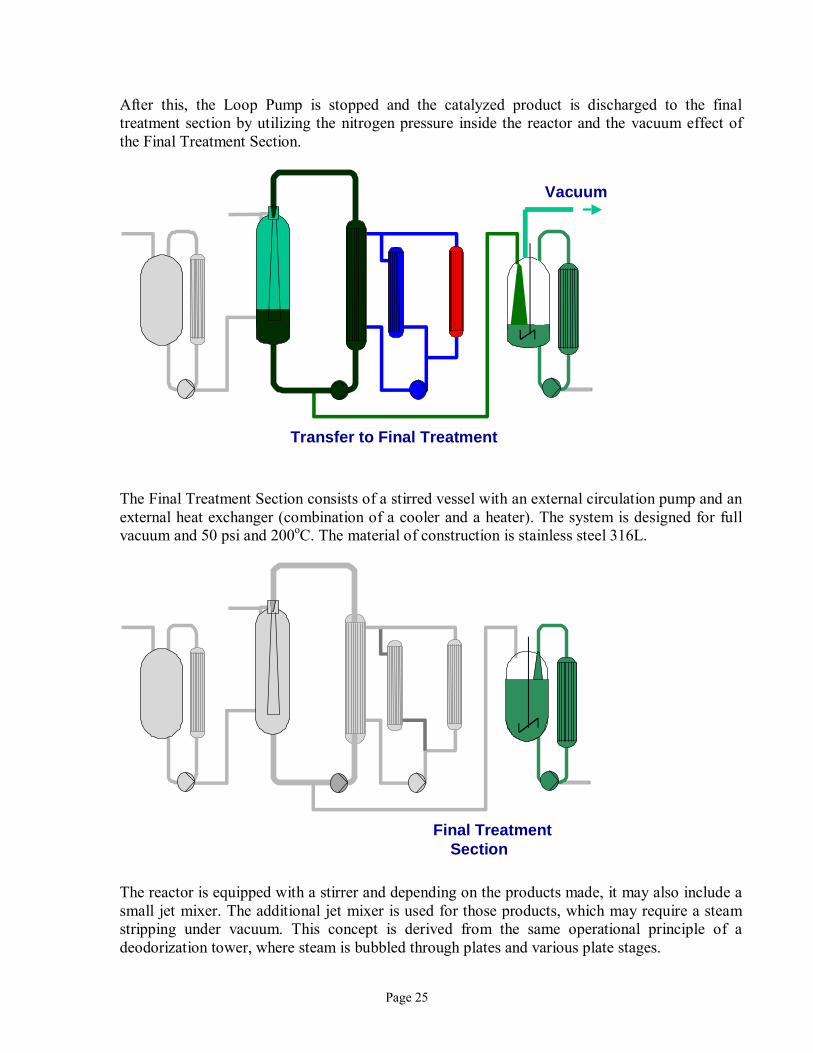
After this, the Loop Pump is stopped and the catalyzed product is discharged to the final treatment section by utilizing the nitrogen pressure inside the reactor and the vacuum effect of the Final Treatment Section.
The Final Treatment Section consists of a stirred vessel with an external circulation pump and an external heat exchanger (combination of a cooler and a heater). The system is designed for full vacuum and 50 psi and 200oC. The material of construction is stainless steel 316L.
The reactor is equipped with a stirrer and depending on the products made, it may also include a small jet mixer. The additional jet mixer is used for those products, which may require a steam stripping under vacuum. This concept is derived from the same operational principle of a deodorization tower, where steam is bubbled through plates and various plate stages.
Vacuum
Transfer to Final Treatment
Final TreatmentSection
Page 26
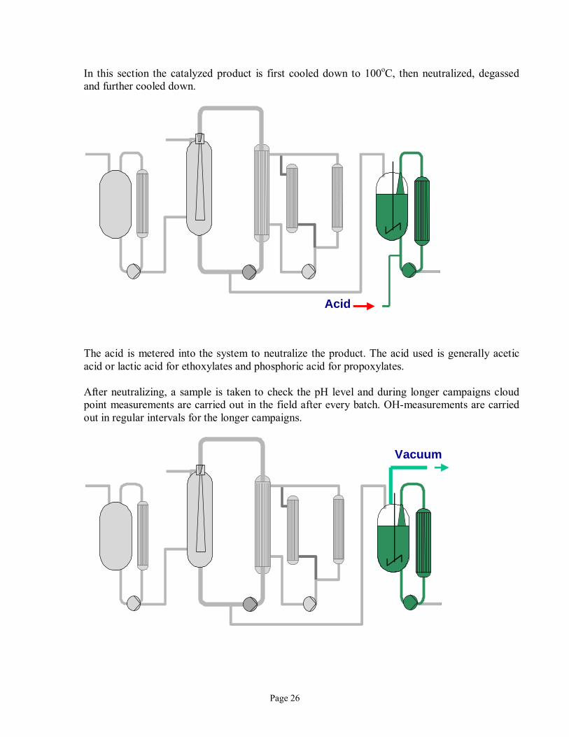
In this section the catalyzed product is first cooled down to 100oC, then neutralized, degassed and further cooled down.
The acid is metered into the system to neutralize the product. The acid used is generally acetic acid or lactic acid for ethoxylates and phosphoric acid for propoxylates. After neutralizing, a sample is taken to check the pH level and during longer campaigns cloud point measurements are carried out in the field after every batch. OH-measurements are carried out in regular intervals for the longer campaigns.
Acid
Vacuum
Page 27
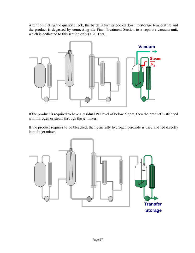
After completing the quality check, the batch is further cooled down to storage temperature and the product is degassed by connecting the Final Treatment Section to a separate vacuum unit, which is dedicated to this section only (< 20 Torr).
If the product is required to have a residual PO level of below 5 ppm, then the product is stripped with nitrogen or steam through the jet mixer. If the product requires to be bleached, then generally hydrogen peroxide is used and fed directly into the jet mixer.
Vacuum
Steam N2
Transfer Storage
Page 28
After this the final product is transferred to storage. If required, such as in the case of propoxylates, then the salt formed during the neutralization needs to be filtered in a Dr. M type filter. This type of filter is now being used in the industry as one of the best closed filter system that is available. This filter successfully fulfills the task of separating salt ions without exposing the operators directly with any of the chemicals as compared to the filter plates historically still in use. Now when looking at a typical PID of a HH Loop Reactor there is a lot more detail to be seen in particular with respect to safety issues in addition to the fast operability of the reactor under inert conditions and being designed to withstand the eventuality of an explosion, for example:
• Double valves around high pressure HH Loop Reactor.
• Fail spring loaded close/ or open valves depending on safest action.
• When operating with an EO or PO feeding pump it is impossible to overfill the
reactor, because the positive pump is limited by its design up to 225 psi.
• The safety relief valve to the HH Loop Reactor is designed for the worst case being an external fire.
• The heating/cooling medium is pressurized above the maximum HH Loop Reactor
pressure, so if there were to be any leaks, then this may only be from the outside towards the inside (Loop Reactor through a tube rupture in heat exchanger).
• Safety assurance that the loop pump is indeed running. This is monitored by
measuring the jet mixer�s pressure difference. Consequently this assures that there is a liquid thrust through the jet mixer and if not, then the EO or PO feeding is immediately interrupted, thus preventing any EO or PO accumulation.
Page 29
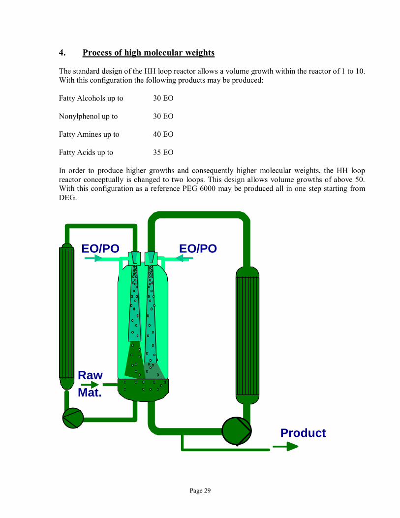
4. Process of high molecular weights The standard design of the HH loop reactor allows a volume growth within the reactor of 1 to 10. With this configuration the following products may be produced: Fatty Alcohols up to 30 EO Nonylphenol up to 30 EO Fatty Amines up to 40 EO Fatty Acids up to 35 EO In order to produce higher growths and consequently higher molecular weights, the HH loop reactor conceptually is changed to two loops. This design allows volume growths of above 50. With this configuration as a reference PEG 6000 may be produced all in one step starting from DEG.
EO/PO EO/PO
Raw Mat.
Product
Page 30
5. Process with narrow range catalyst: The concept to improve or better narrowing the distribution of an ethoxylate has been studied for many years, but in the last 5 to 10 years the consumers and markets have not rewarded the detergent manufacturers in terms of sales for the advantages that these products offer. Most studies were done with linear alcohol ethoxylates and the following advantages were found:
• Peaking reduces the level of unethoxylated alcohol left in the ethoxylate, which consequently improves the odor.
• Peaking reduces the level of high mole homologs, which consequently lowers the melting
point.
• Peaking yields a higher concentration of homologs, which under the assumption that the EO content is optimized, may lead to improved detergency and wetting performance.
The parameters which may influence peaking are the reaction temperature and pressure, EO or PO feeding rates, catalyst and to a minor degree the reactor geometry and mixing power. The biggest influence on peaking ethoxylates is achieved by selecting the right solid catalyst. The chemistry becomes fairly complicated and many producers have developed and patented their own proprietary catalyst: Conoco/Vista Strontium hydroxide, Calcium/aluminium5,6,7,8,9 Henkel hydrotalcite/magnesium/aluminium10 Hoechst Lewis Acid/antimony pentachloride11 Shell Rare Earth12 Union Carbide Calcium13
Page 31
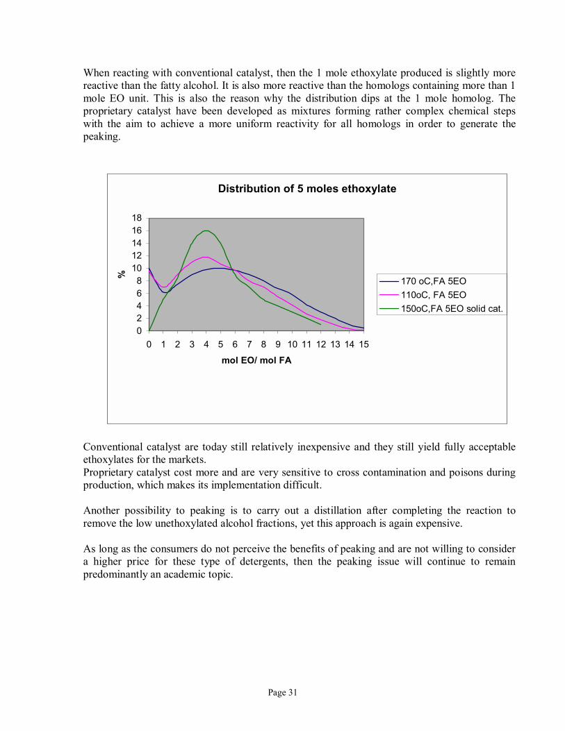
When reacting with conventional catalyst, then the 1 mole ethoxylate produced is slightly more reactive than the fatty alcohol. It is also more reactive than the homologs containing more than 1 mole EO unit. This is also the reason why the distribution dips at the 1 mole homolog. The proprietary catalyst have been developed as mixtures forming rather complex chemical steps with the aim to achieve a more uniform reactivity for all homologs in order to generate the peaking.
Conventional catalyst are today still relatively inexpensive and they still yield fully acceptable ethoxylates for the markets. Proprietary catalyst cost more and are very sensitive to cross contamination and poisons during production, which makes its implementation difficult. Another possibility to peaking is to carry out a distillation after completing the reaction to remove the low unethoxylated alcohol fractions, yet this approach is again expensive. As long as the consumers do not perceive the benefits of peaking and are not willing to consider a higher price for these type of detergents, then the peaking issue will continue to remain predominantly an academic topic.
Distribution of 5 moles ethoxylate
02468
1012141618
0 1 2 3 4 5 6 7 8 9 10 11 12 13 14 15
mol EO/ mol FA
%
170 oC,FA 5EO110oC, FA 5EO150oC,FA 5EO solid cat.
Page 32
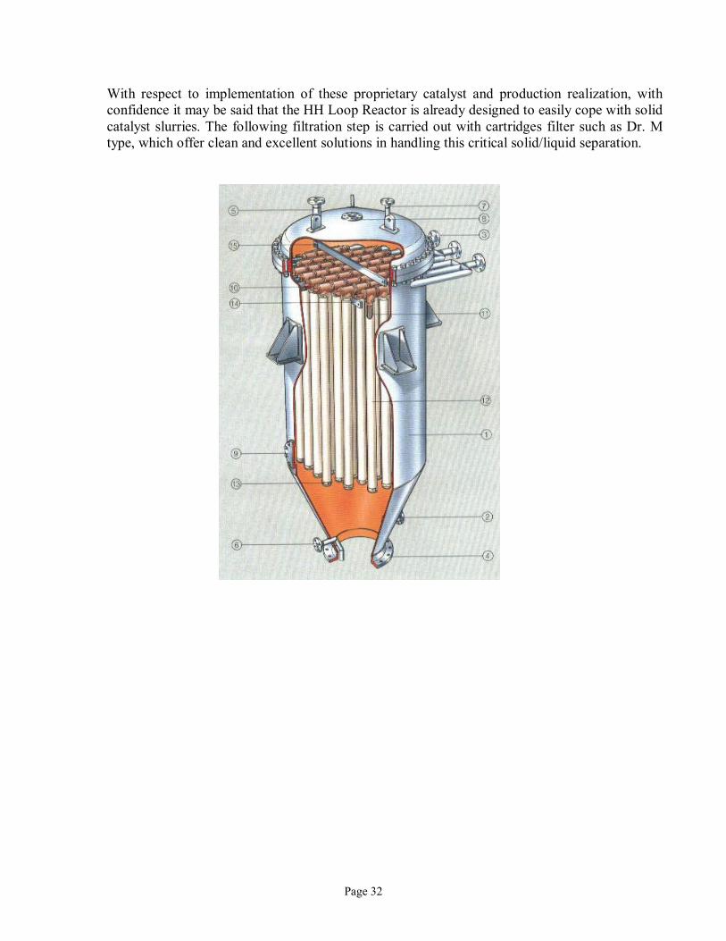
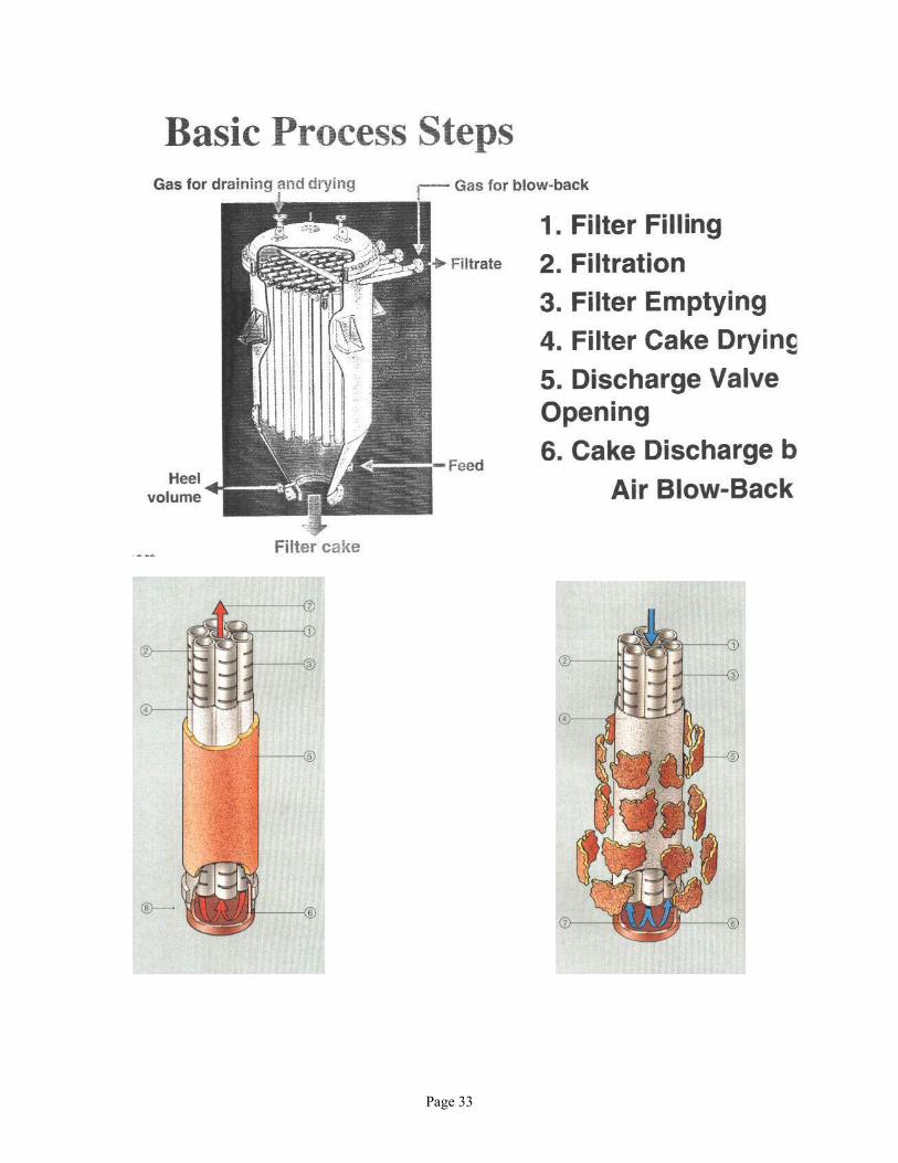
With respect to implementation of these proprietary catalyst and production realization, with confidence it may be said that the HH Loop Reactor is already designed to easily cope with solid catalyst slurries. The following filtration step is carried out with cartridges filter such as Dr. M type, which offer clean and excellent solutions in handling this critical solid/liquid separation.
Page 33
Page 34
6. EO/PO Reactors The EO and PO reaction characteristics are rather different, which makes it somewhat difficult to create an ideal reactor for both types of reactions. It is known that ethoxylations are gas/liquid reactions and mass transfer limited. Propoxylations are much slower in reaction kinetics compared to ethoxylations and are liquid/liquid reactions, which no matter how much more mixing energy is put into the reactor system, the reaction rate will remain the same. The HH Loop Reactor has industrially demonstrated that it may also produce block copolymers of all different starter types. Random copolymers may also be produced, but the ratios of EO to PO need to be adapted differently due to the different reaction rates of ethylene oxide and propylene oxide. Therefore, compared to conventional reactors, the EO and PO feeding percentage ratio needs to be readjusted in order to achieve a specific final product quality. The HH Loop Reactor is able to propoxylate many products for speciality producers such as Bisphenol A, butanols, fatty alcohols, PPGs etc. The reaction rate is slower than that for ethoxylations (400 � 600 kg/hm3 PO feeds compared to 1,000 � 1,500 kg/hm3 EO), but it has all the flexibilities to produce these products as well. When producing polyether polyols for making rigid or flexible polyurethanes, the ideal reactor to be considered is a modified stirred vessel, which is specially designed to discharge the high viscosity material at the end of the reaction. The stirred reactor can more easily cope with the high melting points (sorbitol, glycerol, pentaerythrol etc.) and the high final viscosities.
Page 35
7. Removal of by � products As stated earlier the HH Loop Reactor in general achieves lower residual EO, Dioxane levels, PEG levels and better color. This is primarily achieved due to the Loop Reactor design in particular the Jet Mixer�s function, which promotes much faster reaction kinetics and consequently less side products formation. A further contributing fact to less color formation is the presence of nitrogen, which suppresses the oxygen in solution from discoloring the products. An interesting case analysis is made for stearic acid ethoxylate, which demonstrates how the HH Loop Reactor performs at traditional reaction conditions versus higher pressures. Test Run Partial Pressure EO
(bar abs) Reaction Temp. (oC)
Stage 1/ Stage 2 Dioxane Content
(ppm) # 1 (normal case)
3 170/170 200 �300
# 2 (lower temp.)
3 170/130 40
# 3 (higher pres.)
5 170/130 30
# 4 (higher pres.)
7.5 170/130 20
The results show that with higher pressures in the HH Loop Reactor, lower dioxane levels are formed.
Page 36
8. New trends in Reactor Technology Current reactor technology trends are to further maximize reactor space for more productivity and adapting the flow of raw materials to final products such that the need for storage tanks are reduced. When looking at the batch cycle process, additional savings may be realized for long product campaigns by having the raw material pre-catalyzed in a concentrated form outside of the Workup Vessel. The large producers today have mostly 3 to 5 different production lines in their plants and they try to run these lines for single families of products as much as possible. This reduces the need for washing and consequently more output is achieved. The modern surfactant producer has a range of reactors between conventional stirred reactors and Loop Reactors. This allows the producer to have the maximum flexibility in meeting the market demands. The reduction of utilities is always a topic and this goes a little hand in hand with the development of new equipment and pumps. For production lines that only produce 3 or 5 different products and assuming these products are all more between 5 and 12 moles of EO, then a heat recovery system may be implemented, whereby during the reaction step, instead of cooling with water or air, condensate is used to generate low pressure steam. Considering a future possibility and that peaked ethoxylates may become of greater interest, then the HH Loop Reactor may again be of importance by implementing some new developments taken from other fields, which would comprise the embedding of solid catalyst in a ceramic structure that is placed inside the Jet Mixer. The operating principle would be similar to that of a car catalyzer box. Continuous reactors may be another potential possibility for the future, but as long that most manufacturers are producing such a variety of different products it is difficult to handle the product changes in a continuous mode without having to go through some considerable product losses.
Page 37
References: 1 Etude Produit, Oxyde d�Ethylene, Information Chimie no. 363, - novembre 1994, page 123 � 134 2 Ethylene Oxide, Guidelines for bulk handling, Chemical Industries Association, ISBN 1 85897 043 1,
1996. 3 L. G. Britton, Thermal Stability and Deflagration of Ethylene Oxide, AIChemE, New Orleans, 1988. 4 Verfahren zur sicheren und unweltfreundlichen Ethoxylierung von Fettalkohol, Dr. Leuteritz, Fat Sci.
Technol., 93. Jahrgang Nr. 10 5 US Patent 4,223,164 6 US Patent 4,306,093 7 US Patent 4,302,613 8 US Patent 4,775,653 9 US Patent 4,835,321 10 German Patent DE 4,010,606 A1 11 Canadian Patent 2015434 12 US Patent 5,210,325 13 US Patent 4,820,673 14 US Patent 4,754,075 15 Insights and advantages of the Jet Reactor versus advanced Stirred Reactors for two and three phase
reactions in the petrochemical and chemical industry, Urs Geser, Annual Meeting of the Chinese American Petroleum Association, 15-17 November 1996, Houston, Texas
![B C&% % 1 % 8 : G ':&% I G J & D %7L% . 3 · [ $3 hh hh$#hh 1 [hhh hh hh dhhphh #hhm#hhbhh hh&lhh < w) d?. {lhh hh$ @b#-p 3 c 3:;hhh $# #" )j p d] #hhm#hhbhh hh&x %hh | x4 3 hh?hh](https://img.pdfslide.tips/doc/110x75/5ea61d5cbec94348cc54f9a5/b-c-1-8-g-i-g-j-d-7l-3-3-hh-hhhh-1-hhh-hh-hh.jpg)


![HH SULPHURaulasptmariareinaeskola.es/app/download/9102134/1Dicta... · /hh sulphur ',&7$'2 3hur fxdqgr ho dluh ylhqh gh duuled gh odv fuhvwdv qhydgdv ho kxpr hq yh] gh vxelu d or](https://img.pdfslide.tips/doc/110x75/61006943f2ec4c7ba57673d5/hh-sulphuraul-hh-sulphur-72-3hur-fxdqgr-ho-dluh-ylhqh-gh-duuled-gh-odv.jpg)