Embed Size (px)
Citation preview
Hier wird Wissen Wirklichkeit Computer Architecture – Part 9 – page 1 of 84 – Prof. Dr. Uwe Brinkschulte, Prof. Dr. Klaus Waldschmidt
Part 9Instruction Level Parallelism (ILP) - Concurrency
Computer Architecture
Slide Sets
WS 2011/2012
Prof. Dr. Uwe BrinkschulteProf. Dr. Klaus Waldschmidt
Hier wird Wissen Wirklichkeit Computer Architecture – Part 9 – page 2 of 84 – Prof. Dr. Uwe Brinkschulte, Prof. Dr. Klaus Waldschmidt
Concurrency
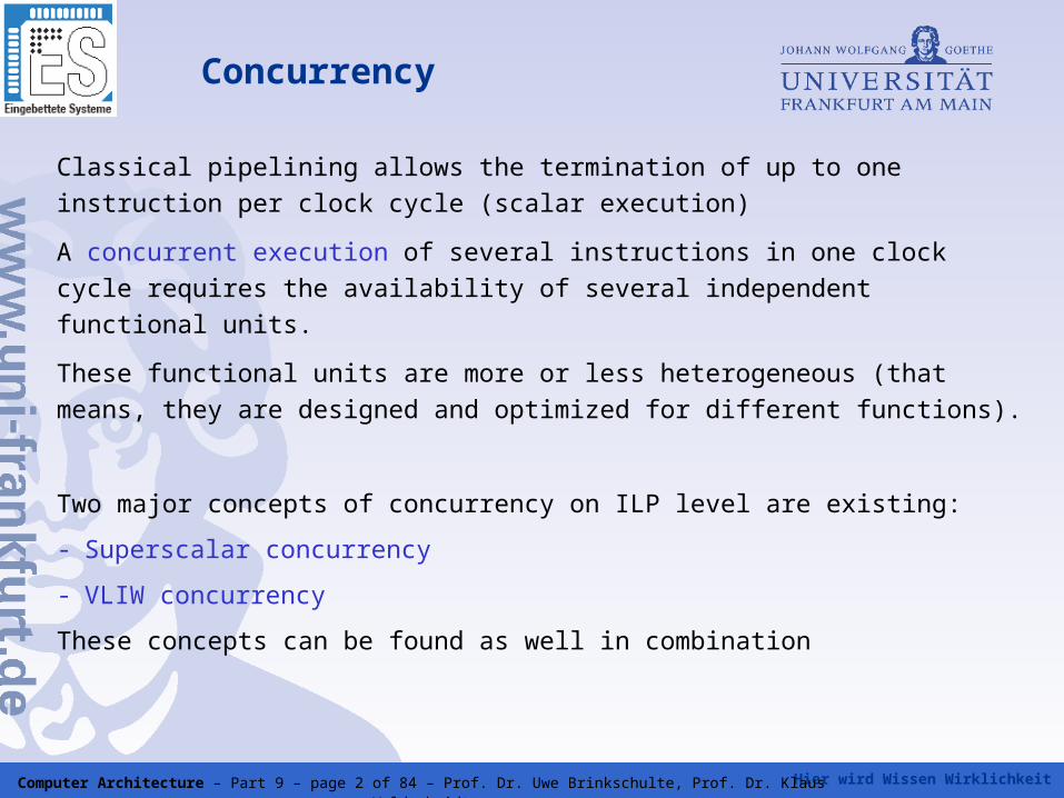
Classical pipelining allows the termination of up to one instruction per clock
cycle (scalar execution)
A concurrent execution of several instructions in one clock cycle requires
the availability of several independent functional units.
These functional units are more or less heterogeneous (that means, they
are designed and optimized for different functions).
Two major concepts of concurrency on ILP level are existing:
- Superscalar concurrency
- VLIW concurrency
These concepts can be found as well in combination
Hier wird Wissen Wirklichkeit Computer Architecture – Part 9 – page 3 of 84 – Prof. Dr. Uwe Brinkschulte, Prof. Dr. Klaus Waldschmidt
Concurrency - superscalar
The superscalar technique operates on a conventional sequential
instruction stream
The concurrent instruction issue is performed completely during runtime
by hardware.
This technique requires a lot of hardware resources.
It allows a very efficient dynamic issue of instructions at runtime.
On the downside, no long running dependency analysis (as e.g.
possible by a compiler) is possible
Hier wird Wissen Wirklichkeit Computer Architecture – Part 9 – page 4 of 84 – Prof. Dr. Uwe Brinkschulte, Prof. Dr. Klaus Waldschmidt
Concurrency - superscalar
The superscaler technique is a pure microarchitecture technique, since
it is not visible on the architectural level (conventional sequential
instruction stream)
Thus, hardware structure (e.g. the number of parallel execution units)
can be changed without changing the architectural specifications
(e.g. ISA)
Superscaler execution is usually combined with pipelining (superscalar
pipeline)
Hier wird Wissen Wirklichkeit Computer Architecture – Part 9 – page 5 of 84 – Prof. Dr. Uwe Brinkschulte, Prof. Dr. Klaus Waldschmidt
Concurrency - VLIW
The VLIW technique (Very Large Instruction Word) operates on a parallel
instruction stream.
The concurrent instruction issue is organized statically with the support of
the compiler.
The consequence is a lower amount of hardware resources.
Extensive compiler optimizations are possible to exploit parallelism.
On the downside, no dynamic effects can be considered (e.g. branch
prediction is difficult in VLIW).
Hier wird Wissen Wirklichkeit Computer Architecture – Part 9 – page 6 of 84 – Prof. Dr. Uwe Brinkschulte, Prof. Dr. Klaus Waldschmidt
Concurrency - VLIW
VLIW is a architectural technique, since the parallel instruction stream is
visible on the architectural level.
Therefore, a change in e.g. the level of parallelism leads to a change in the
architectural specifications
VLIW is usually combined with pipelining
VLIW can also be combined with superscaler concepts, as e.g done in
EPIC (Explicit Parallel Instruction Computing, Intel Itanium)
Hier wird Wissen Wirklichkeit Computer Architecture – Part 9 – page 7 of 84 – Prof. Dr. Uwe Brinkschulte, Prof. Dr. Klaus Waldschmidt
The main question in designing a concurrent computer architecture is:
How many instruction level parallelism (ILP) exists in the code of an
application?
This question has been analyzed very extensively for the compilation
of a sequential imperative programming language in a RISC instruction
set.
The result of all these analyses is:
Programs include a fine grain parallelism degree of 5-7.
Degree of parallelism in ILP
Hier wird Wissen Wirklichkeit Computer Architecture – Part 9 – page 8 of 84 – Prof. Dr. Uwe Brinkschulte, Prof. Dr. Klaus Waldschmidt
Higher degrees in parallelism can be obtained only by code with
long basic blocks (long instruction sequences without branches).
Numerical applications in combination with loop unrolling is an
application class with a higher ILP.
Further application classes are embedded system control.
A computer architecture for general purpose applications with a
higher ILP of 5-7 can suffer from decreasing efficiency because of a
lot of idle functional units.
Degree of parallelism in ILP
Hier wird Wissen Wirklichkeit Computer Architecture – Part 9 – page 9 of 84 – Prof. Dr. Uwe Brinkschulte, Prof. Dr. Klaus Waldschmidt
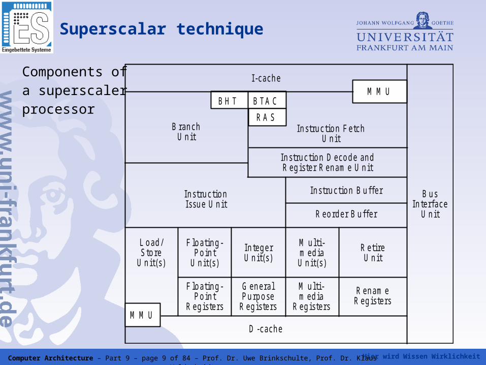
Superscalar technique
Components ofa superscaler processor
L o ad /S to re
U n it(s )
F lo a tin g -P o in t
R eg is te rs
G en e ra lP u rp o se
R eg is te rs
M u lti-m ed ia
R eg is te rs
F lo a tin g -P o in t
U n it(s )
In teg e rU n it(s )
M u lti-m ed iaU n it(s )
R e tireU n it
R en am eR eg is te rs
D -cach eM M U
R eo rd e r B u ffe r
In s tru c tio n B u ffe rIn s tru c tio nIssu e U n it
In s tru c tio n D eco d e an dR eg is te r R en am e U n it
In s tru c tio n F e tchU n it
B ran chU n it
B H T B TA C
R A S
M M UI-cach e
B u sIn te rface
U n it
Hier wird Wissen Wirklichkeit Computer Architecture – Part 9 – page 10 of 84 – Prof. Dr. Uwe Brinkschulte, Prof. Dr. Klaus Waldschmidt
Superscalar technique
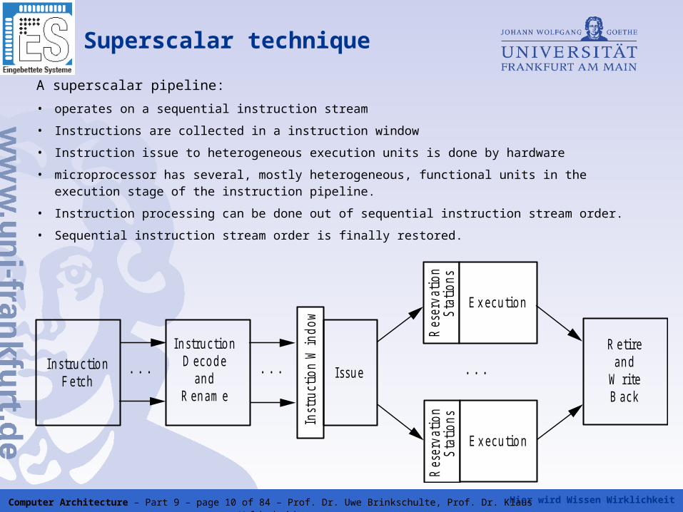
A superscalar pipeline:
• operates on a sequential instruction stream
• Instructions are collected in a instruction window
• Instruction issue to heterogeneous execution units is done by hardware
• microprocessor has several, mostly heterogeneous, functional units in the execution stage of the instruction pipeline.
• Instruction processing can be done out of sequential instruction stream order.
• Sequential instruction stream order is finally restored.
In s tru c tio n F e tch
. . .
In s tru c tio n D eco d e
an d R en am e
. . .
Inst
ruct
ion
Win
dow
I s su e
Res
erva
tion
St
atio
ns
E x ecu tio n
Res
erva
tion
St
atio
nsE x ecu tio n
. . .
R etire an d
W rite B ack
Hier wird Wissen Wirklichkeit Computer Architecture – Part 9 – page 11 of 84 – Prof. Dr. Uwe Brinkschulte, Prof. Dr. Klaus Waldschmidt
Superscalar technique
In s tru c tio n F e tch
. . .
In s tru c tio n D eco d e
an d R en am e
. . .
Inst
ruct
ion
Win
dow
I s su e
Res
erva
tion
St
atio
ns
E x ecu tio n
Res
erva
tion
St
atio
ns
E x ecu tio n
. . .
R etire an d
W rite B ack
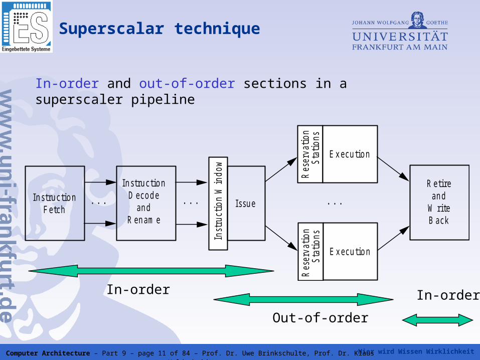
In-order and out-of-order sections in a superscaler pipeline
In-order In-order
Out-of-order
Hier wird Wissen Wirklichkeit Computer Architecture – Part 9 – page 12 of 84 – Prof. Dr. Uwe Brinkschulte, Prof. Dr. Klaus Waldschmidt
Instruction fetch
• Loads several instructions (instruction block) from the nearest instruction memory (e.g. instruction cache) to an instruction buffer
• Ususally, as many instructions are fetched per clock cycle as can be issued to the execution units (fetch bandwidth)
• Control flow conflicts are solved by branch prediction and branch target address cache
• The instruction buffer decouples instruction fetch from decode
Hier wird Wissen Wirklichkeit Computer Architecture – Part 9 – page 13 of 84 – Prof. Dr. Uwe Brinkschulte, Prof. Dr. Klaus Waldschmidt
Instruction fetch
• Cache level Harvard architecture
• Self-modifying code cannot be implemented efficiently on todays superscaler processors
• Instruction cache (single port) mostly simpler organized than data cache (multi port)
• In case of branches, instructions have to be fetched from different cache blocks
• Solutions to parallelize this: multi-channel caches, interleaved caches, multiple instructions fetch units, trace cache
Hier wird Wissen Wirklichkeit Computer Architecture – Part 9 – page 14 of 84 – Prof. Dr. Uwe Brinkschulte, Prof. Dr. Klaus Waldschmidt
Decode
• Decodes multiple instructions per clock cycle
• Decode bandwidth usually equal to fetch bandwidth
• Fixed length instruction format simplifies decoding of several instructions per clock cycle
• Variable instruction length => multi stage decoding
• first stage: determinde instruction boundaries
• second stage: decode instructions and create one or more microinstructions
• complex CISC instructions are splitted to simpler RISC instructions
Hier wird Wissen Wirklichkeit Computer Architecture – Part 9 – page 15 of 84 – Prof. Dr. Uwe Brinkschulte, Prof. Dr. Klaus Waldschmidt
Register rename
• Goal of register renaming: remove false dependencies (output dependency, anti dependency)
• Renaming can be done:
• statically by the compiler
• dynamically by hardware
• Dynamic register renaming:
• architectural registers are mapped to physical registers
• each destination register specified in the instruction is mapped to a free physical register
• the following instructions having the same architectural register as source register will get last assigned physical register as input operand by register renaming
=> false dependencies between register operands are removed
Hier wird Wissen Wirklichkeit Computer Architecture – Part 9 – page 16 of 84 – Prof. Dr. Uwe Brinkschulte, Prof. Dr. Klaus Waldschmidt
Register rename
Two possible implementations:
• two different register sets are present
• architectural registers store the „valid“ values
• rename buffer registers store temporary results
• on renaming, architectural registers are assigned to buffer registers
• only one register set of so-called physical registers is present
• these store temporary and valid values
• architectural registers are mapped to physical registers
• architectural registers themselves are physically non-existent
• a mapping table defines which physical register currently operates as which architectural register for a given instruction
Hier wird Wissen Wirklichkeit Computer Architecture – Part 9 – page 17 of 84 – Prof. Dr. Uwe Brinkschulte, Prof. Dr. Klaus Waldschmidt
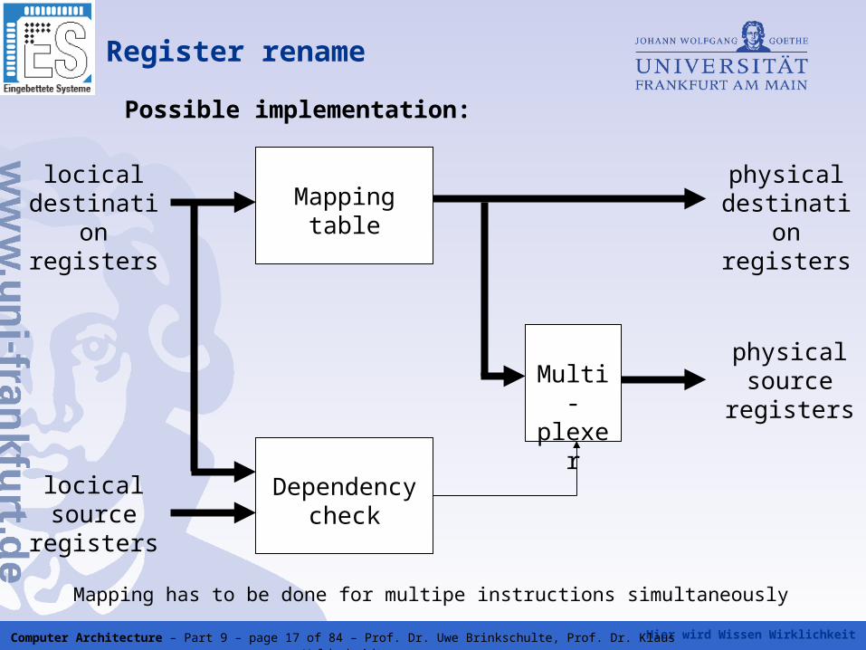
Register rename
Mapping tablelocical
destination registers
physical destination registers
locical source
registers
Dependency check
Multi-plexer
physical source
registers
Mapping has to be done for multipe instructions simultaneously
Possible implementation:
Hier wird Wissen Wirklichkeit Computer Architecture – Part 9 – page 18 of 84 – Prof. Dr. Uwe Brinkschulte, Prof. Dr. Klaus Waldschmidt
Instruction window
• Decoded instructions are written to the instruction window
• The instruction window decouples fetch/decode from execution
• The instructions in the instruction window are
• free of control flow dependencies due to branch prediction
• free of false dependencies due to register renaming
• True dependencies and resource dependencies remain
• Instruction issue checks in each clock cycle, which instructions from instruction window can be issued to the execution units
• These are issued up to the maximum issue bandwidth (number of execution units)
• The original instruction sequence is stored in the reorder buffer
Hier wird Wissen Wirklichkeit Computer Architecture – Part 9 – page 19 of 84 – Prof. Dr. Uwe Brinkschulte, Prof. Dr. Klaus Waldschmidt
Instruction window and issueterminology
• issue means the assignment of instructions to execution units or preceeding reservation stations, if present (see e.g. Tomasulo alg.)
• if reservation stations are present, the assignment of instructions from reservation stations to the execution units is called dispatch
• the instruction issue policy describes the protcoll used to select instructions for issuing
• depending on the processor instructions can be issued in-order or out- of-order
• the lookahead capability determines, how may instructions in the instruction window can be inspected to find the next issuable instructions
• the issuing logic determining executable instructions often is called scheduler
Hier wird Wissen Wirklichkeit Computer Architecture – Part 9 – page 20 of 84 – Prof. Dr. Uwe Brinkschulte, Prof. Dr. Klaus Waldschmidt
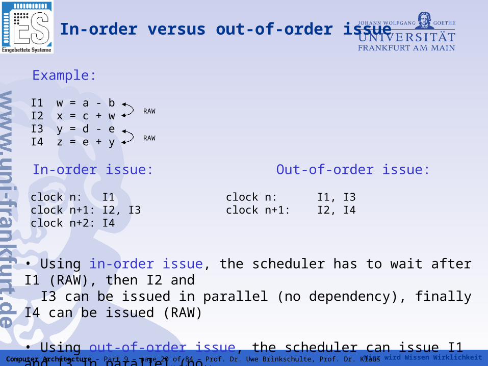
In-order versus out-of-order issue
Example:
I1 w = a - b I2 x = c + w I3 y = d - e I4 z = e + y
In-order issue: Out-of-order issue:
clock n: I1 clock n: I1, I3 clock n+1: I2, I3 clock n+1: I2, I4 clock n+2: I4
• Using in-order issue, the scheduler has to wait after I1 (RAW), then I2 and I3 can be issued in parallel (no dependency), finally I4 can be issued (RAW)
• Using out-of-order issue, the scheduler can issue I1 and I3 in parallel (no dependeny), followed by I2 and I4 => one clock cycle is saved
RAW
RAW
Hier wird Wissen Wirklichkeit Computer Architecture – Part 9 – page 21 of 84 – Prof. Dr. Uwe Brinkschulte, Prof. Dr. Klaus Waldschmidt
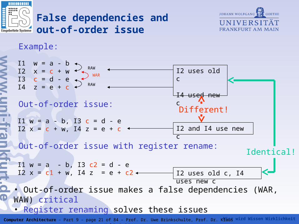
False dependencies andout-of-order issue
Example:
I1 w = a - b I2 x = c + w I3 c = d - e I4 z = e + c
Out-of-order issue:
I1 w = a - b, I3 c = d - e I2 x = c + w, I4 z = e + c
Out-of-order issue with register rename:
I1 w = a - b, I3 c2 = d - e I2 x = c1 + w, I4 z = e + c2
• Out-of-order issue makes a false dependencies (WAR, WAW) critical• Register renaming solves these issues
RAW
RAW
WARI2 uses old c
I4 used new c
Different!
I2 and I4 use new c
I2 uses old c, I4 uses new c
Identical!
Hier wird Wissen Wirklichkeit Computer Architecture – Part 9 – page 22 of 84 – Prof. Dr. Uwe Brinkschulte, Prof. Dr. Klaus Waldschmidt
Scheduling techniques
There are several possible techniques to determine and
issue the next executable instructions, e.g.:
• Associative memory
(central solution)
• Tomasulo algorithm
(decentral solution)
• Scoreboard
(central solution)
Hier wird Wissen Wirklichkeit Computer Architecture – Part 9 – page 23 of 84 – Prof. Dr. Uwe Brinkschulte, Prof. Dr. Klaus Waldschmidt
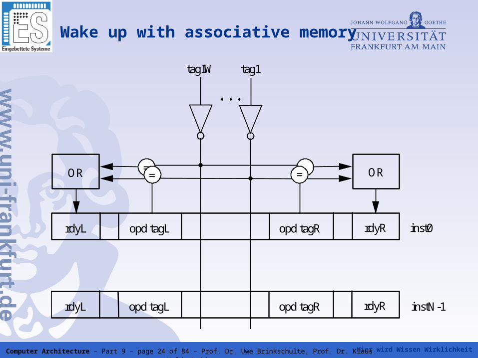
Wake up with associative memory
• The instructions waiting in the instruction window are marked by so
called tags.
• The tags of the produced results are compared with the tags of the
operands of the waiting instructions.
• For comparison, each window cell is equipped with comparators.
All comparators are working in parallel.
• This kind of a memory is called associative memory.
• A hit of comparison is marked by a ready bit.
• If the ready bits of an instruction are complete, the instruction is
issued.
• This solves the true dependencies
Hier wird Wissen Wirklichkeit Computer Architecture – Part 9 – page 24 of 84 – Prof. Dr. Uwe Brinkschulte, Prof. Dr. Klaus Waldschmidt
Wake up with associative memory
rdyL opd tagL opd tagR rdyR
OR = = = = OR
. . .
tagIW tag1
inst0
. . . rdyL opd tagL opd tagR rdyR instN-1
. . .
Hier wird Wissen Wirklichkeit Computer Architecture – Part 9 – page 25 of 84 – Prof. Dr. Uwe Brinkschulte, Prof. Dr. Klaus Waldschmidt
Priority based issuing of instructions woken up
• If there are more instruction determined for issuing then available execution units (issue bandwidth), a priority selection logic is necessary
• This selection logic determines for each execution unit the instruction to issue from the woken up instructions
• Therefore, each execution unit needs such a selection unit
• This solves the resource dependencies
• The hardware complexity of the issue unit rises with the size of the instruction window and the number of execution units
Hier wird Wissen Wirklichkeit Computer Architecture – Part 9 – page 26 of 84 – Prof. Dr. Uwe Brinkschulte, Prof. Dr. Klaus Waldschmidt
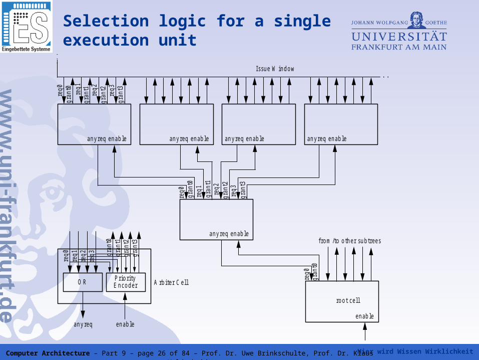
Selection logic for a single execution unit
req0
gran
t0re
q1gr
ant1
req2
gran
t2re
q3gr
ant3
a n y req en ab le an y req en ab le an y req en ab le an y req en ab le
. . .
. . .Issu e W in d o w
req0
gran
t0re
q1gr
ant1
req2
gran
t2re
q3gr
ant3
a n y req en ab le
req0
req1
req2
req3 gr
ant0
gran
t1gr
ant2
gran
t3
A rb ite r C e llO R P rio rityE n co d e r
an y req en a b le
req0
gran
t0e n ab le
ro o t ce ll
fro m /to o th e r su b tree s
Hier wird Wissen Wirklichkeit Computer Architecture – Part 9 – page 27 of 84 – Prof. Dr. Uwe Brinkschulte, Prof. Dr. Klaus Waldschmidt
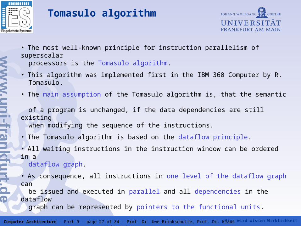
Tomasulo algorithm
• The most well-known principle for instruction parallelism of superscalar
processors is the Tomasulo algorithm.
• This algorithm was implemented first in the IBM 360 Computer by R. Tomasulo.
• The main assumption of the Tomasulo algorithm is, that the semantic of a program is unchanged, if the data dependencies are still existing when modifying the sequence of the instructions.
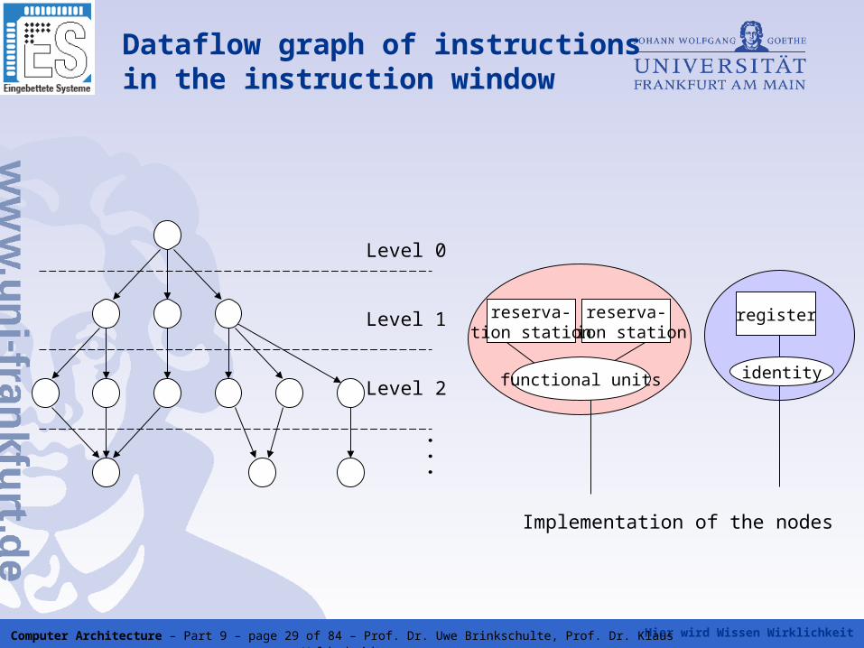
• The Tomasulo algorithm is based on the dataflow principle.
• All waiting instructions in the instruction window can be ordered in a dataflow graph.
• As consequence, all instructions in one level of the dataflow graph can be issued and executed in parallel and all dependencies in the dataflow graph can be represented by pointers to the functional units.
Hier wird Wissen Wirklichkeit Computer Architecture – Part 9 – page 28 of 84 – Prof. Dr. Uwe Brinkschulte, Prof. Dr. Klaus Waldschmidt
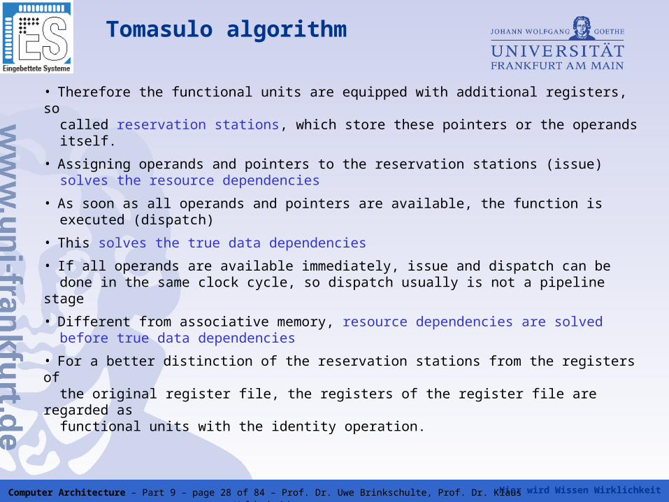
Tomasulo algorithm
• Therefore the functional units are equipped with additional registers, so called reservation stations, which store these pointers or the operands itself.
• Assigning operands and pointers to the reservation stations (issue) solves the resource dependencies
• As soon as all operands and pointers are available, the function is executed (dispatch)
• This solves the true data dependencies
• If all operands are available immediately, issue and dispatch can be done in the same clock cycle, so dispatch usually is not a pipeline stage
• Different from associative memory, resource dependencies are solved before true data dependencies
• For a better distinction of the reservation stations from the registers of the original register file, the registers of the register file are regarded as functional units with the identity operation.
Hier wird Wissen Wirklichkeit Computer Architecture – Part 9 – page 29 of 84 – Prof. Dr. Uwe Brinkschulte, Prof. Dr. Klaus Waldschmidt
Dataflow graph of instructions in the instruction window
Level 0
Level 1
Level 2
...
reserva-tion station
reserva-tion station
register
identityfunctional units
Implementation of the nodes
Hier wird Wissen Wirklichkeit Computer Architecture – Part 9 – page 30 of 84 – Prof. Dr. Uwe Brinkschulte, Prof. Dr. Klaus Waldschmidt
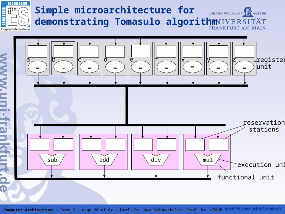
Simple microarchitecture for demonstrating Tomasulo algorithm
functional unit
execution unit
reservationstations
mul
= = = = = = = = =registerunit
a b c d e f x y z
divaddsub
Hier wird Wissen Wirklichkeit Computer Architecture – Part 9 – page 31 of 84 – Prof. Dr. Uwe Brinkschulte, Prof. Dr. Klaus Waldschmidt
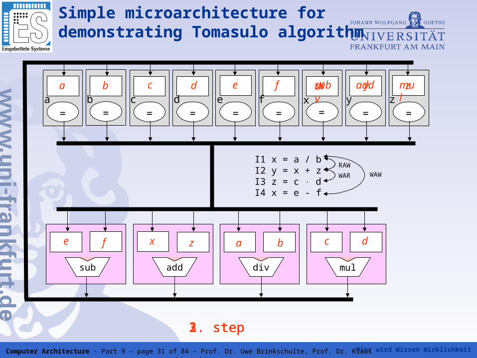
Simple microarchitecture for demonstrating Tomasulo algorithm
mul
= = = = = = = = =a b c d e f x y z
zfedca b
divaddsub
a bz c de f
I1 x = a / bI2 y = x + zI3 z = c dI4 x = e - f
RAW
WAR WAW
1. step
div add mul
2. step
x
x
sub
3. step
y
Hier wird Wissen Wirklichkeit Computer Architecture – Part 9 – page 32 of 84 – Prof. Dr. Uwe Brinkschulte, Prof. Dr. Klaus Waldschmidt
Execution of the program sequence on the microarchitecture
First step: instructions I1 - I4 and the available operands are issued to the corresponding reservation stations
reservation stations of the results are reserverd for I1, I2 and I3
result reservation station for I4 cannot be reserved because already occupied by result of I1
Second step: instructions I1 and I3 are dispatched because all operands and result space are available
result of I1 is transferred to the reservation station where I2 is waiting
therefore, result reservation station occupied by I1 so far becomes free and is now reserved for I4
Third step: instructions I2 and I4 are dispatched now and the results are stored
Hier wird Wissen Wirklichkeit Computer Architecture – Part 9 – page 33 of 84 – Prof. Dr. Uwe Brinkschulte, Prof. Dr. Klaus Waldschmidt
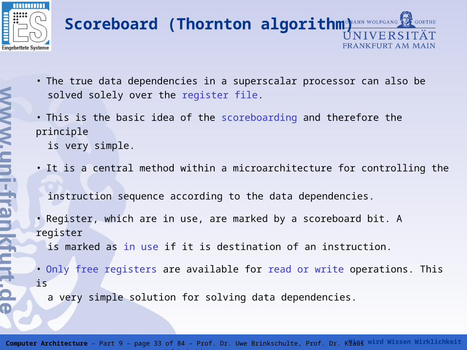
Scoreboard (Thornton algorithm)
• The true data dependencies in a superscalar processor can also be
solved solely over the register file.
• This is the basic idea of the scoreboarding and therefore the principle
is very simple.
• It is a central method within a microarchitecture for controlling the
instruction sequence according to the data dependencies.
• Register, which are in use, are marked by a scoreboard bit. A register
is marked as in use if it is destination of an instruction.
• Only free registers are available for read or write operations. This is
a very simple solution for solving data dependencies.
Hier wird Wissen Wirklichkeit Computer Architecture – Part 9 – page 34 of 84 – Prof. Dr. Uwe Brinkschulte, Prof. Dr. Klaus Waldschmidt
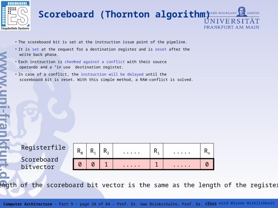
Scoreboard (Thornton algorithm)
R0 R1 R2 ..... Ri ..... Rn
0 0 1 ..... 01 .....
The length of the scoreboard bit vector is the same as the length of the register file.
Registerfile
Scoreboardbitvector
• The scoreboard bit is set at the instruction issue point of the pipeline.
• It is set at the request for a destination register and is reset after the write back phase.
• Each instruction is checked against a conflict with their source operands and a “in use” destination register.
• In case of a conflict, the instruction will be delayed until the scoreboard bit is reset. With this simple method, a RAW-conflict is solved.
Hier wird Wissen Wirklichkeit Computer Architecture – Part 9 – page 35 of 84 – Prof. Dr. Uwe Brinkschulte, Prof. Dr. Klaus Waldschmidt
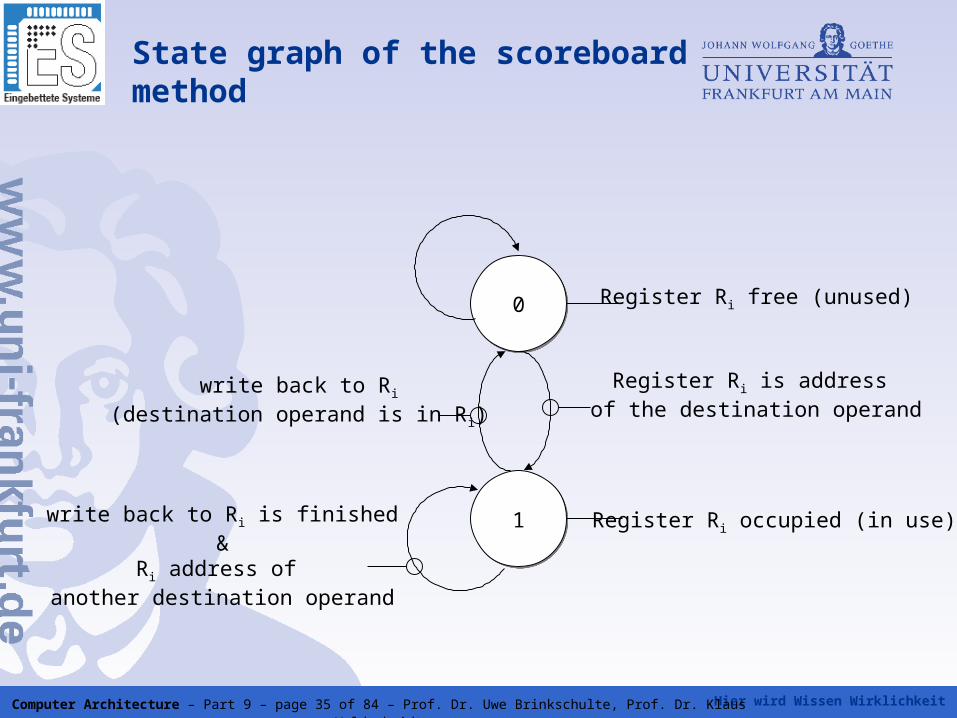
State graph of the scoreboard method
00
11
Register Ri free (unused)
Register Ri is address of the destination operand
Register Ri occupied (in use)write back to Ri is finished&
Ri address of another destination operand
write back to Ri
(destination operand is in Ri)
Hier wird Wissen Wirklichkeit Computer Architecture – Part 9 – page 36 of 84 – Prof. Dr. Uwe Brinkschulte, Prof. Dr. Klaus Waldschmidt
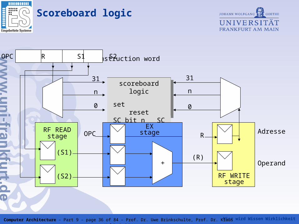
Scoreboard logic
instruction word
scoreboardlogic
set resetSC bit n SC bit n
RF READstage
(S1)
(S2)
+
OPCEX
stage
RF WRITEstage
Adresse
Operand
R
(R)
31
n
0
31
n
0
OPC R S1 S2
Hier wird Wissen Wirklichkeit Computer Architecture – Part 9 – page 37 of 84 – Prof. Dr. Uwe Brinkschulte, Prof. Dr. Klaus Waldschmidt
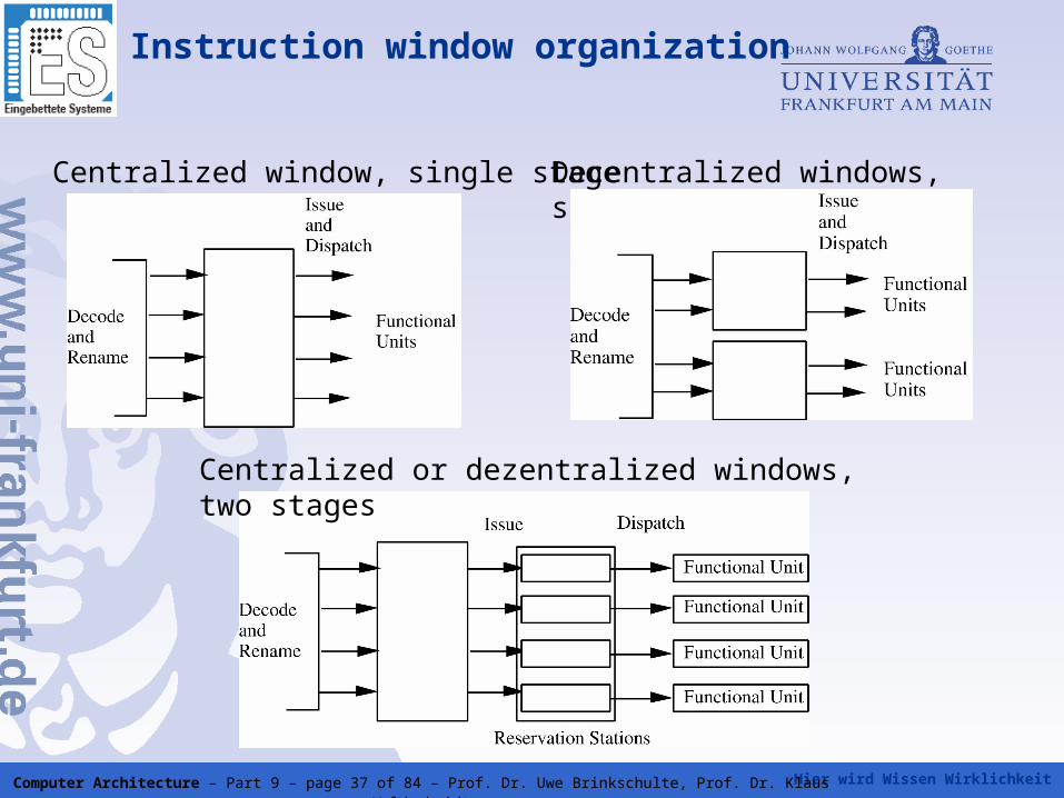
Instruction window organization
Decentralized windows, single stageCentralized window, single stage
Centralized or dezentralized windows, two stages
Hier wird Wissen Wirklichkeit Computer Architecture – Part 9 – page 38 of 84 – Prof. Dr. Uwe Brinkschulte, Prof. Dr. Klaus Waldschmidt
Execution
• Out-of-order execution of the instructions in mostly parallel execution units
• Results are store in the rename buffers or physical registers
• Execution units can be
• single cycle units (execution takes a single clock cycle), latency = throughput = 1
• multiple cycle units (execution takes multiple clock cycles), latency > 1
• with pipelining (e.g. arithmetic pipeline), throughput = 1
• without pipelining (e.g. load-/store-unit - possible cache misses), throughput = 1 / latency
Hier wird Wissen Wirklichkeit Computer Architecture – Part 9 – page 39 of 84 – Prof. Dr. Uwe Brinkschulte, Prof. Dr. Klaus Waldschmidt
Execution
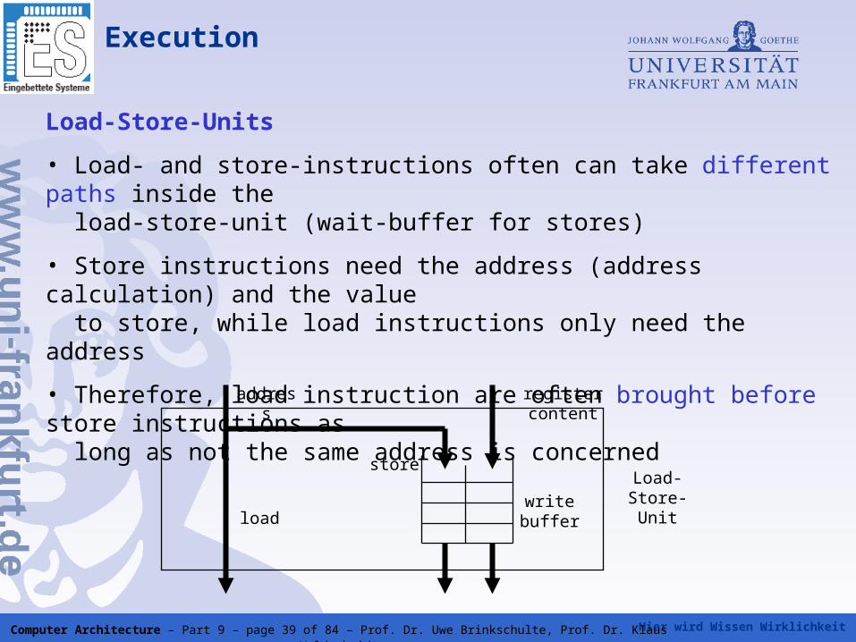
Load-Store-Units
• Load- and store-instructions often can take different paths inside the load-store-unit (wait-buffer for stores)
• Store instructions need the address (address calculation) and the value to store, while load instructions only need the address
• Therefore, load instruction are often brought before store instructions as long as not the same address is concerned
write bufferload
store
address register content
Load-Store-Unit
Hier wird Wissen Wirklichkeit Computer Architecture – Part 9 – page 40 of 84 – Prof. Dr. Uwe Brinkschulte, Prof. Dr. Klaus Waldschmidt
Execution
Load-Store-Units
• A load instruction is completed, as soon as the value to load is written to a buffer register
• A store instruction is completed, as soon as the value is written to the cache
• This cannot be undone!
• So store instructions on a speculative path (branch prediction) cannot be completed before the speculation is confirmed to be true
• Speculative load instructions are not a problem
Hier wird Wissen Wirklichkeit Computer Architecture – Part 9 – page 41 of 84 – Prof. Dr. Uwe Brinkschulte, Prof. Dr. Klaus Waldschmidt
Execution
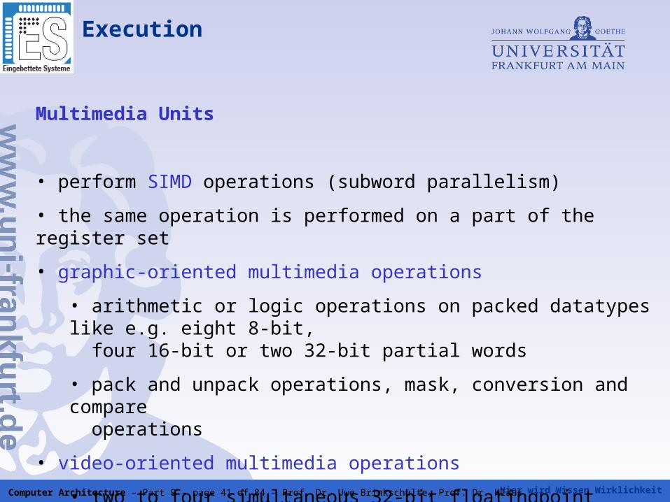
Multimedia Units
• perform SIMD operations (subword parallelism)
• the same operation is performed on a part of the register set
• graphic-oriented multimedia operations
• arithmetic or logic operations on packed datatypes like e.g. eight 8-bit, four 16-bit or two 32-bit partial words
• pack and unpack operations, mask, conversion and compare operations
• video-oriented multimedia operations
• two to four simultaneous 32-bit floatingpoint operations
Hier wird Wissen Wirklichkeit Computer Architecture – Part 9 – page 42 of 84 – Prof. Dr. Uwe Brinkschulte, Prof. Dr. Klaus Waldschmidt
Retire and write back
Retire and write back is responsible for:
• commiting or discarding the completed results from execution
• rolling back wrong speculation paths from branch prediction
• restoring the original sequential instruction order
• allowing precise interrupts or exceptions
Hier wird Wissen Wirklichkeit Computer Architecture – Part 9 – page 43 of 84 – Prof. Dr. Uwe Brinkschulte, Prof. Dr. Klaus Waldschmidt
Some wordings
Completion of an instruction:
• The execution unit has finished the execution of the instruction
• The results are written to temporary buffer registers and are available as operands for data-dependend instructions
• Completion is done out of order
• During completion, the position of the instruction in the original instruction sequence and the current completion state is stored in a reorder buffer
• The completion state might indicate a preceding interrupt/exception or a pending speculation for this instruction
Hier wird Wissen Wirklichkeit Computer Architecture – Part 9 – page 44 of 84 – Prof. Dr. Uwe Brinkschulte, Prof. Dr. Klaus Waldschmidt
Some wordings
Commitment of an instruction:
• Commitment is done in the original instruction order (in-order)
• A result of an instruction can be commited, if
• execution is completed
• the results of all instructions preceding this instruction in the original instruction order are committed or will be committed within the same clock cycle
• no interrupt/exception occured before or during execution
• the execution does no longer depend on any speculation
• During commitment the results are written permanently to the architectural
registers
• Committed instructions are removed from the reorder buffer
Hier wird Wissen Wirklichkeit Computer Architecture – Part 9 – page 45 of 84 – Prof. Dr. Uwe Brinkschulte, Prof. Dr. Klaus Waldschmidt
Some wordings
Removement of an instruction:
• The instruction is removed from the reorder buffer without committing it
• All results of the instructions are discarded
• This is done e.g. in case of misspeculation or a preceding interrupt/exception
Retirement of an instruction
• The instruction is removed from the reorder buffer with or without committing it (commitment or removement)
Hier wird Wissen Wirklichkeit Computer Architecture – Part 9 – page 46 of 84 – Prof. Dr. Uwe Brinkschulte, Prof. Dr. Klaus Waldschmidt
Interrupts and exceptions
On an interrupt or exception, the regular program flow is interrupted and an interrupt service routine (exception handler) is called
Classes of interrupts/exceptions:
Aborts:are very fatal and lead to processor shutdownReasons: hardware failures like defective memory cells
Traps: are fatal and normally lead to program terminationReasons: arithmetic errors (overflow, underflow, division by 0),
privilege violation, invalid opcode, …
Faults: cause the repetition of the last executed instruction after handlingReasons: virtual memory management errors like page faults
External interrupts: lead to interrupt handling Reasons: interrupts from external devices to indicate the presence of data or timer events
Software interrupts: lead to interrupt handling Reasons: interrupt instruction in program
Hier wird Wissen Wirklichkeit Computer Architecture – Part 9 – page 47 of 84 – Prof. Dr. Uwe Brinkschulte, Prof. Dr. Klaus Waldschmidt
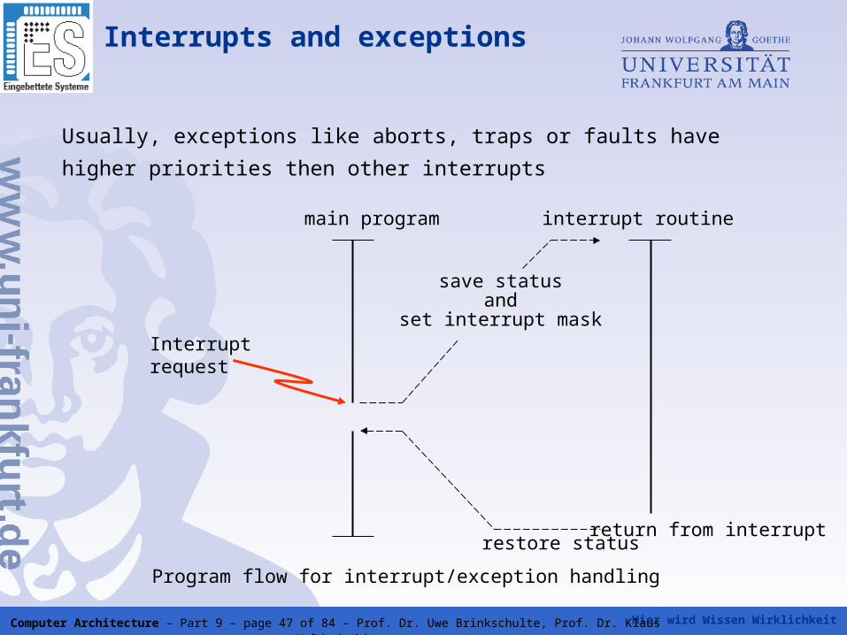
Usually, exceptions like aborts, traps or faults have higher priorities then other
interrupts
Interruptrequest
save statusand
set interrupt mask
return from interrupt
main program interrupt routine
Program flow for interrupt/exception handling
restore status
Interrupts and exceptions

Hier wird Wissen Wirklichkeit Computer Architecture – Part 9 – page 48 of 84 – Prof. Dr. Uwe Brinkschulte, Prof. Dr. Klaus Waldschmidt
An interrupt or exception is called precise, if the processor state saved at the start of the interrupt routine is identical to a sequential in order execution on a von-Neumann-architecture
For out-of-order execution on a superscaler processor this means:
• all instructions preceding the interrupt causing instruction are
committed and therefore have modified the processor state
• all instructions succeeding the interrupt causing instruction are
removed and therefore have not influenced the processor state
• depending on the interrupt causing instruction, it is either committed
or removed
Precise interrupts and exceptions
Hier wird Wissen Wirklichkeit Computer Architecture – Part 9 – page 49 of 84 – Prof. Dr. Uwe Brinkschulte, Prof. Dr. Klaus Waldschmidt
The reorder buffer stores the sequential order of the issued instructions and therefore allows result serialization during retirement
The reorder bandwidth is usually identical to the issue bandwidth
Possible reorder buffer organization:
• contains instruction states only
• contains instruction states and results (combination of reorder buffer and rename buffer register)
Alternate reorder techniques:
• ceckpoint repair
• history buffer
Reorder buffer
Hier wird Wissen Wirklichkeit Computer Architecture – Part 9 – page 50 of 84 – Prof. Dr. Uwe Brinkschulte, Prof. Dr. Klaus Waldschmidt
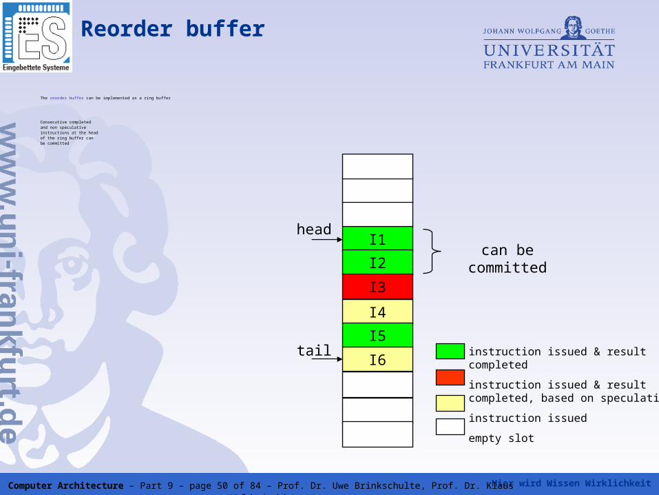
The reorder buffer can be implemented as a ring buffer
Consecutive completed and non speculativeinstructions at the headof the ring buffer canbe committed
Reorder buffer
I1
I2
I3
I4
I5
I6instruction issued & result completed
instruction issued & result completed, based on speculation
instruction issued
empty slot
head
tail
can be committed
Hier wird Wissen Wirklichkeit Computer Architecture – Part 9 – page 51 of 84 – Prof. Dr. Uwe Brinkschulte, Prof. Dr. Klaus Waldschmidt
• Serialization is done to maintain the sequential von-Neumann principle on the architectural level
• Out-of-order commitment is not allowed on today's superscaler processors
• Single exception: bringing load instructions before store instructions is allowed on some processors
• From the outside, a superscalar processor looks like a simple von- Neumann computer
• This is
– good for program verification
– bad for parallel processing
Why serialization during commitment?
Hier wird Wissen Wirklichkeit Computer Architecture – Part 9 – page 52 of 84 – Prof. Dr. Uwe Brinkschulte, Prof. Dr. Klaus Waldschmidt
Very Long Instruction Word (VLIW)architecture
In contrast to the superscaler technique, which is a microarchitectural technique, VLIW is a architectural technique
While in superscaler technique, the parallelism is exploited by hardware, in VLIW this is done by software
The compiler bundles a fixed set of simple independent instructions, which are stored in a very long instruction word
The processor executes all instructions of this very long instruction word in parallel
Hier wird Wissen Wirklichkeit Computer Architecture – Part 9 – page 53 of 84 – Prof. Dr. Uwe Brinkschulte, Prof. Dr. Klaus Waldschmidt
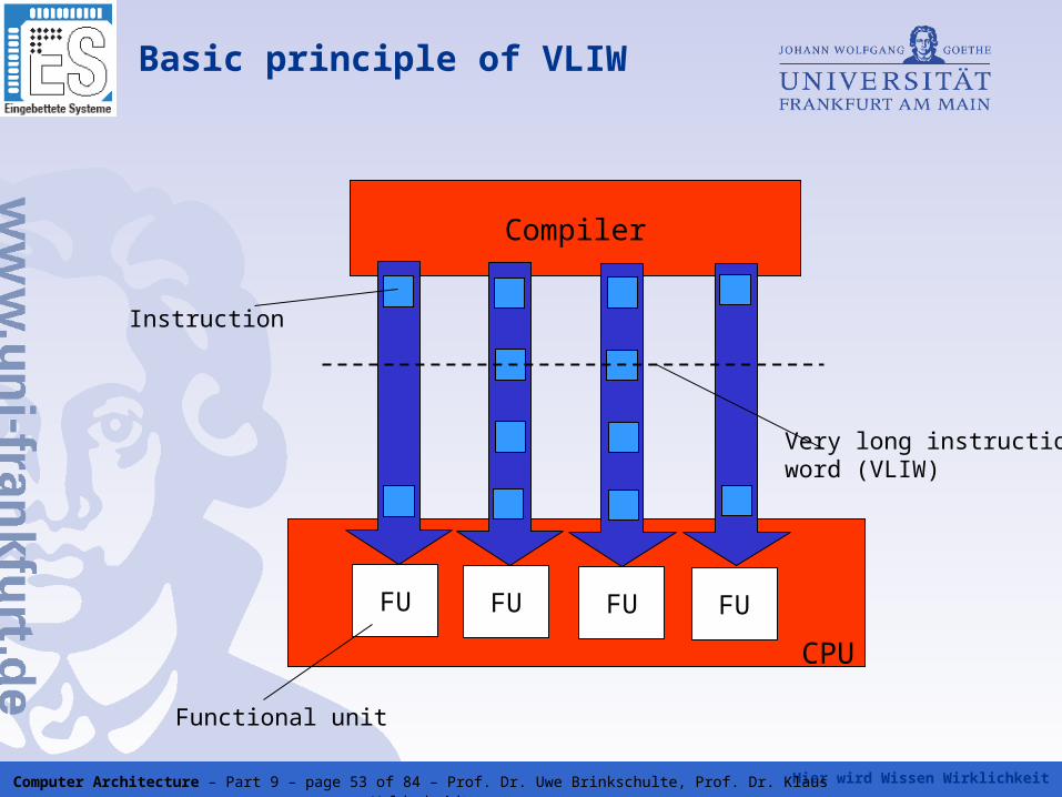
Basic principle of VLIW
Compiler
FU FU FU FU
CPU
Very long instructionword (VLIW)
Functional unit
Instruction
Hier wird Wissen Wirklichkeit Computer Architecture – Part 9 – page 54 of 84 – Prof. Dr. Uwe Brinkschulte, Prof. Dr. Klaus Waldschmidt
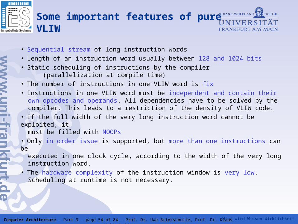
Some important features of pureVLIW
• Sequential stream of long instruction words• Length of an instruction word usually between 128 and 1024 bits• Static scheduling of instructions by the compiler
(parallelization at compile time)• The number of instructions in one VLIW word is fix• Instructions in one VLIW word must be independent and contain their own opcodes and operands. All dependencies have to be solved by the compiler. This leads to a restriction of the density of VLIW code.• If the full width of the very long instruction word cannot be exploited, it must be filled with NOOPs• Only in order issue is supported, but more than one instructions can be executed in one clock cycle, according to the width of the very long instruction word.• The hardware complexity of the instruction window is very low. Scheduling at runtime is not necessary.
Hier wird Wissen Wirklichkeit Computer Architecture – Part 9 – page 55 of 84 – Prof. Dr. Uwe Brinkschulte, Prof. Dr. Klaus Waldschmidt
VLIW instruction vs. CISC and SIMDinstruction
• Difference to a CISC instruction:
A CISC instruction can code several potentially sequential operations in one instruction, while VLIW contains independent parallel operations
• Difference to a SIMD instruction
SIMD instructions perform a single operation on multiple data elements, while VLIW instructions perform different operations on different data elements
Hier wird Wissen Wirklichkeit Computer Architecture – Part 9 – page 56 of 84 – Prof. Dr. Uwe Brinkschulte, Prof. Dr. Klaus Waldschmidt
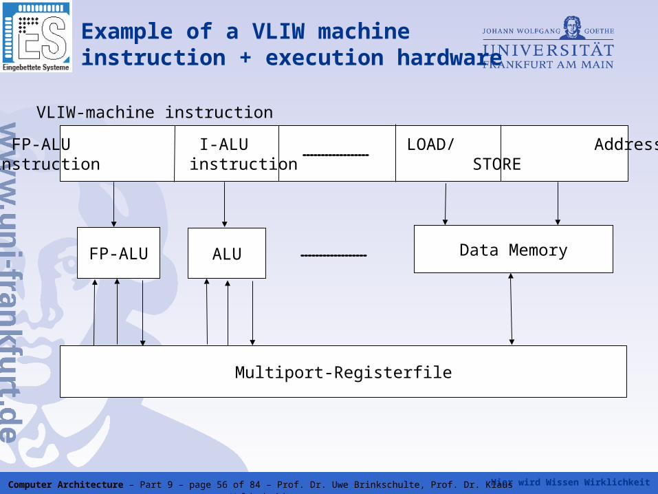
FP-ALU I-ALU LOAD/ Addressinstruction instruction STORE
FP-ALU ALU Data Memory
Multiport-Registerfile
VLIW-machine instruction
Example of a VLIW machine instruction + execution hardware
Hier wird Wissen Wirklichkeit Computer Architecture – Part 9 – page 57 of 84 – Prof. Dr. Uwe Brinkschulte, Prof. Dr. Klaus Waldschmidt
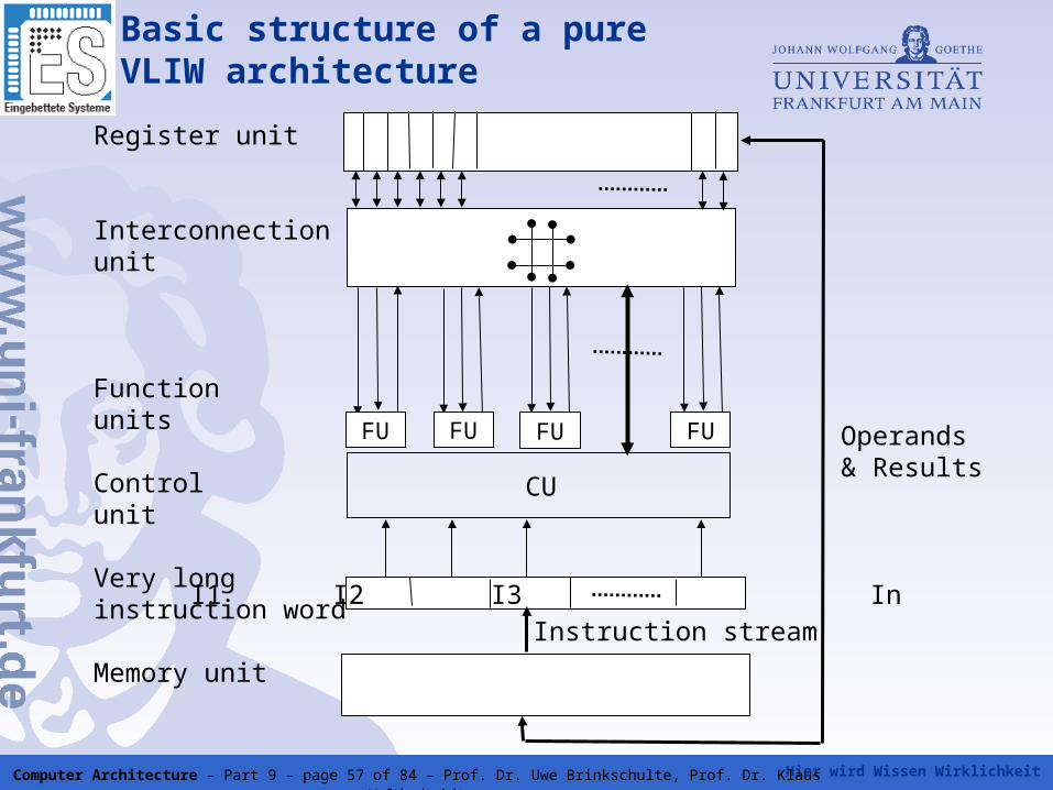
Basic structure of a pure VLIW architecture
I1 I2 I3 In
CU
Instruction stream
Operands& Results
Register unit
Interconnectionunit
Functionunits
Controlunit
Very longinstruction word
Memory unit
FU FU FU FU
Hier wird Wissen Wirklichkeit Computer Architecture – Part 9 – page 58 of 84 – Prof. Dr. Uwe Brinkschulte, Prof. Dr. Klaus Waldschmidt
Basic structure of a pure VLIW architecture
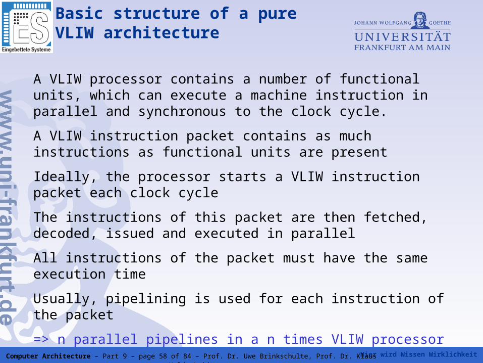
A VLIW processor contains a number of functional units, which can execute a machine instruction in parallel and synchronous to the clock cycle.
A VLIW instruction packet contains as much instructions as functional units are present
Ideally, the processor starts a VLIW instruction packet each clock cycle
The instructions of this packet are then fetched, decoded, issued and executed in parallel
All instructions of the packet must have the same execution time
Usually, pipelining is used for each instruction of the packet
=> n parallel pipelines in a n times VLIW processor
Hier wird Wissen Wirklichkeit Computer Architecture – Part 9 – page 59 of 84 – Prof. Dr. Uwe Brinkschulte, Prof. Dr. Klaus Waldschmidt
Problems with pure VLIW
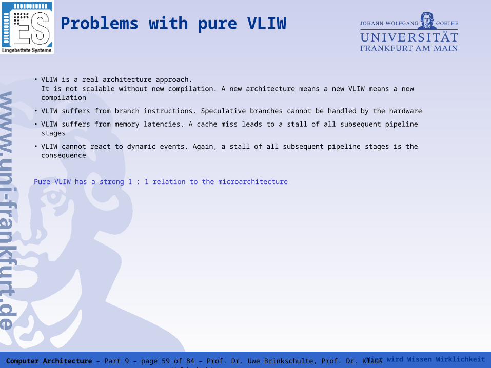
• VLIW is a real architecture approach.It is not scalable without new compilation. A new architecture means a new VLIW means a new compilation
• VLIW suffers from branch instructions. Speculative branches cannot be handled by the hardware
• VLIW suffers from memory latencies. A cache miss leads to a stall of all subsequent pipeline stages
• VLIW cannot react to dynamic events. Again, a stall of all subsequent pipeline stages is the consequence
Pure VLIW has a strong 1 : 1 relation to the microarchitecture
Hier wird Wissen Wirklichkeit Computer Architecture – Part 9 – page 60 of 84 – Prof. Dr. Uwe Brinkschulte, Prof. Dr. Klaus Waldschmidt
Code morphing in VLIW
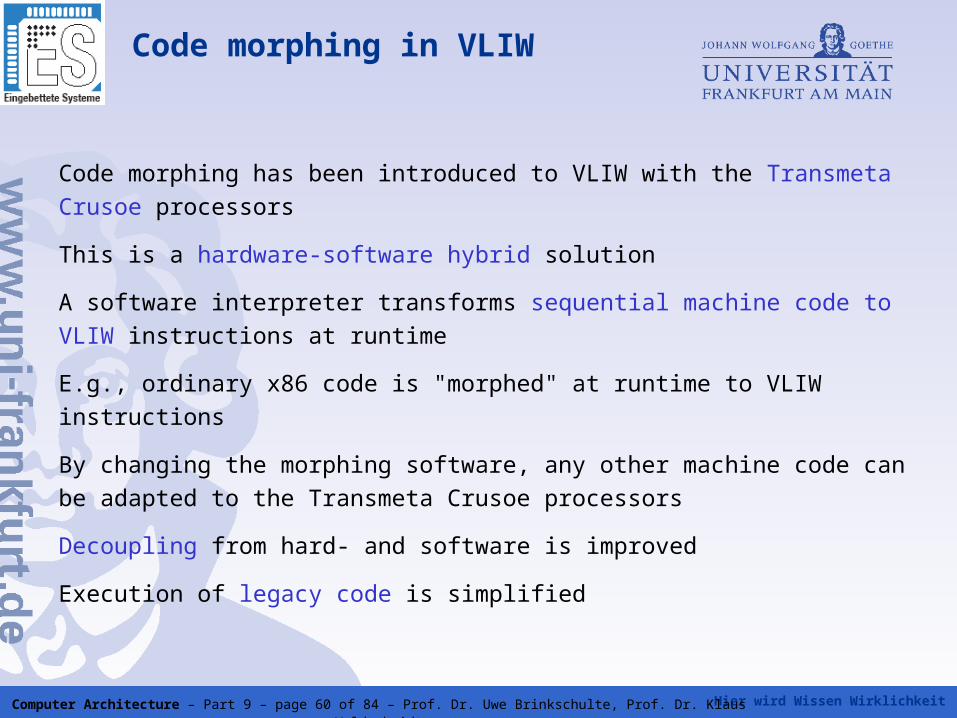
Code morphing has been introduced to VLIW with the Transmeta Crusoe
processors
This is a hardware-software hybrid solution
A software interpreter transforms sequential machine code to VLIW
instructions at runtime
E.g., ordinary x86 code is "morphed" at runtime to VLIW instructions
By changing the morphing software, any other machine code can be
adapted to the Transmeta Crusoe processors
Decoupling from hard- and software is improved
Execution of legacy code is simplified
Hier wird Wissen Wirklichkeit Computer Architecture – Part 9 – page 61 of 84 – Prof. Dr. Uwe Brinkschulte, Prof. Dr. Klaus Waldschmidt
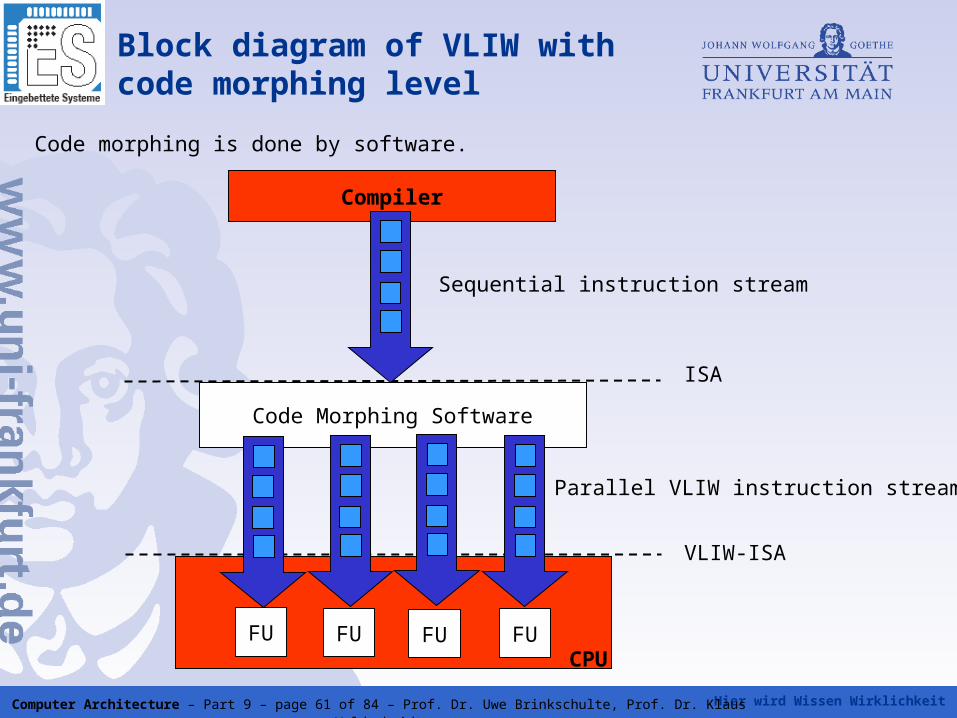
Compiler
Code Morphing Software
FU FU FU FUCPU
ISA
VLIW-ISA
Block diagram of VLIW with code morphing level
Code morphing is done by software.
Sequential instruction stream
Parallel VLIW instruction stream
Hier wird Wissen Wirklichkeit Computer Architecture – Part 9 – page 62 of 84 – Prof. Dr. Uwe Brinkschulte, Prof. Dr. Klaus Waldschmidt
Principle of Code Morphing
Translation of a "virtual" instruction stream to a "real" instruction stream
Code can be optimized during the translation process in several steps:
• The first translation is performed without optimization in the so called
lowest execution mode
• Furthermore, the virtual instructions are instrumented to prepare a profile
of the timing behavior
• The prepared profile can initiate an optimization of the program path.
The binary translation is started again and a revised real VLIW instruction
stream is generated
• This procedure can be repeated several times, until an optimized VLIW
code is available at a high level of execution mode.
Hier wird Wissen Wirklichkeit Computer Architecture – Part 9 – page 63 of 84 – Prof. Dr. Uwe Brinkschulte, Prof. Dr. Klaus Waldschmidt
VLIW architecture with code morphing by Transmeta
Original goal of Transmeta:
- Fast CPUs with low power consumption on the basis of VLIW
and CMOS
- Reduction of hardware complexity by additional software shell.
Crusoe architectures consists of a VLIW hardware core and a
software shell.
- Code morphing software translates X86 instructions into VLIW
code at runtime.
Hier wird Wissen Wirklichkeit Computer Architecture – Part 9 – page 64 of 84 – Prof. Dr. Uwe Brinkschulte, Prof. Dr. Klaus Waldschmidt
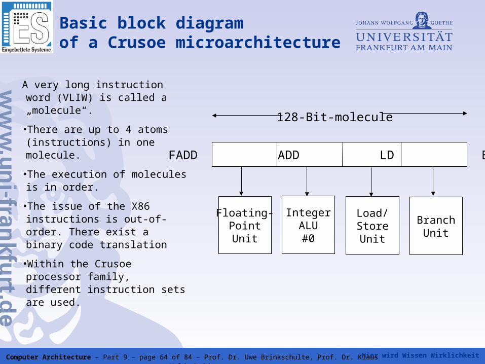
Basic block diagram of a Crusoe microarchitecture
A very long instruction word (VLIW) is called a „molecule“.
•There are up to 4 atoms (instructions) in one molecule.
•The execution of molecules is in order.
•The issue of the X86 instructions is out-of-order. There exist a binary code translation
•Within the Crusoe processor family, different instruction sets are used.
FADD ADD LD BRCC
Floating-PointUnit
IntegerALU#0
Load/StoreUnit
BranchUnit
128-Bit-molecule
Hier wird Wissen Wirklichkeit Computer Architecture – Part 9 – page 65 of 84 – Prof. Dr. Uwe Brinkschulte, Prof. Dr. Klaus Waldschmidt
Crusoe features
The processors are optimized for low power consumption.
Crusoe are VLIW architectures with an additional code morphing software. The
translation of code is “on demand” and is stored in the cache.
On an instruction cache miss, new code is translated to VLIW code.
This code is the executed until the next cache miss
By separating the hardware from the application, a "virtual programming
environment" is created, which supports:
• regular VLIW code execution
• speculative load and store instructions
• prediction
• code instrumentation for optimization.
Hier wird Wissen Wirklichkeit Computer Architecture – Part 9 – page 66 of 84 – Prof. Dr. Uwe Brinkschulte, Prof. Dr. Klaus Waldschmidt
EPIC (Explicitly Parallel InstructionComputing)
• Improvement of VLIW by Intel ad HP to the IA-64 architecture for 64
bit server processors
• Extended 3-instruction format, similar to 3 times VLIW
• Gloal of EPIC: combine simplicity and high clock frequency of a VLIW processor with the advantages of dynamic scheduling
• The EPIC format allows the compiler to inform the processor directly about instruction level parallelism
• Therefore, an EPIC processor ideally has not to check for data and control flow dependencies
• This simplifies the microarchitecture compared to a superscaler processor while improving flexibility compared to VLIW processor
Hier wird Wissen Wirklichkeit Computer Architecture – Part 9 – page 67 of 84 – Prof. Dr. Uwe Brinkschulte, Prof. Dr. Klaus Waldschmidt
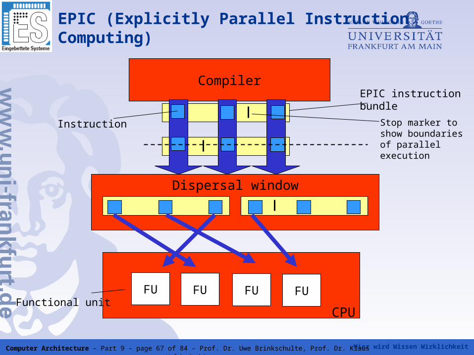
Compiler
EPIC (Explicitly Parallel InstructionComputing)
FU FU FU FU
CPU
EPIC instructionbundle
Functional unit
Instruction
Dispersal window
Stop marker to show boundaries of parallel execution
Hier wird Wissen Wirklichkeit Computer Architecture – Part 9 – page 68 of 84 – Prof. Dr. Uwe Brinkschulte, Prof. Dr. Klaus Waldschmidt
EPIC (Explicitly Parallel InstructionComputing)
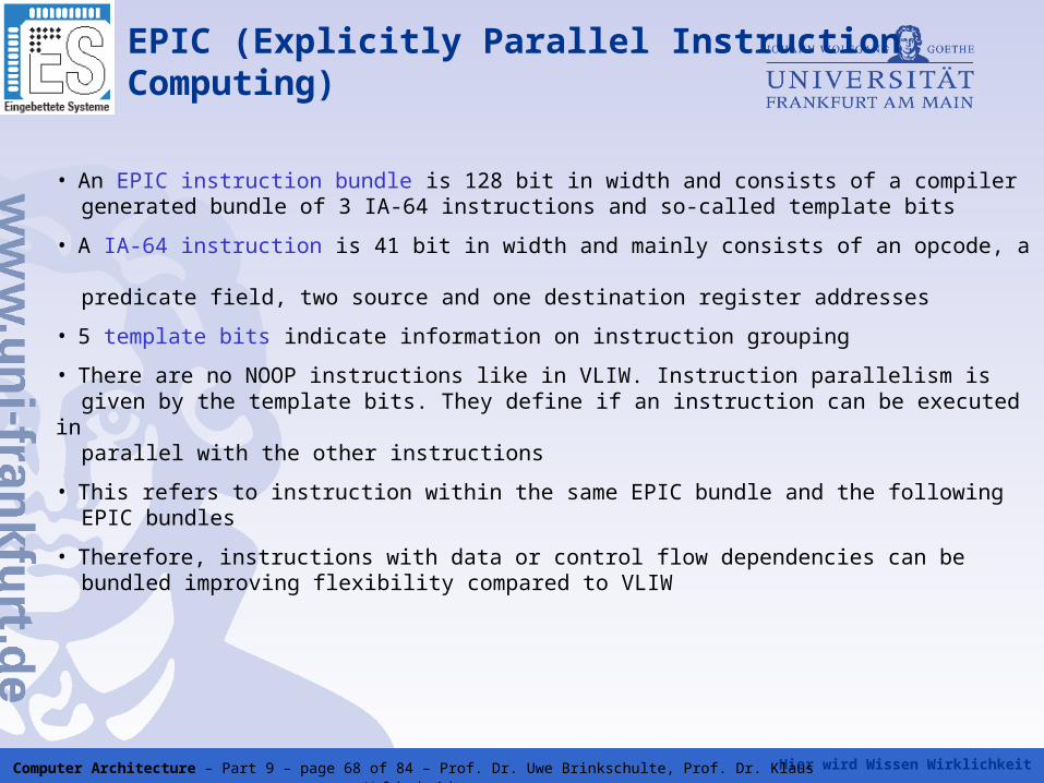
• An EPIC instruction bundle is 128 bit in width and consists of a compiler generated bundle of 3 IA-64 instructions and so-called template bits
• A IA-64 instruction is 41 bit in width and mainly consists of an opcode, a predicate field, two source and one destination register addresses
• 5 template bits indicate information on instruction grouping
• There are no NOOP instructions like in VLIW. Instruction parallelism is given by the template bits. They define if an instruction can be executed in parallel with the other instructions
• This refers to instruction within the same EPIC bundle and the following EPIC bundles
• Therefore, instructions with data or control flow dependencies can be bundled improving flexibility compared to VLIW
Hier wird Wissen Wirklichkeit Computer Architecture – Part 9 – page 69 of 84 – Prof. Dr. Uwe Brinkschulte, Prof. Dr. Klaus Waldschmidt
EPIC (Explicitly Parallel InstructionComputing)
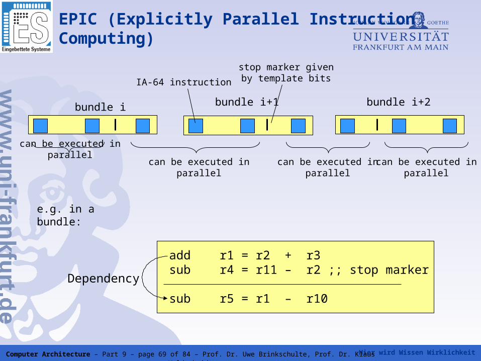
bundle i bundle i+1 bundle i+2
can be executed in parallel
can be executed in parallel
can be executed in parallel
can be executed in parallel
stop marker given by template bitsIA-64 instruction
add r1 = r2 + r3sub r4 = r11 – r2 ;; stop marker
sub r5 = r1 – r10
Dependency
e.g. in a bundle:
Hier wird Wissen Wirklichkeit Computer Architecture – Part 9 – page 70 of 84 – Prof. Dr. Uwe Brinkschulte, Prof. Dr. Klaus Waldschmidt
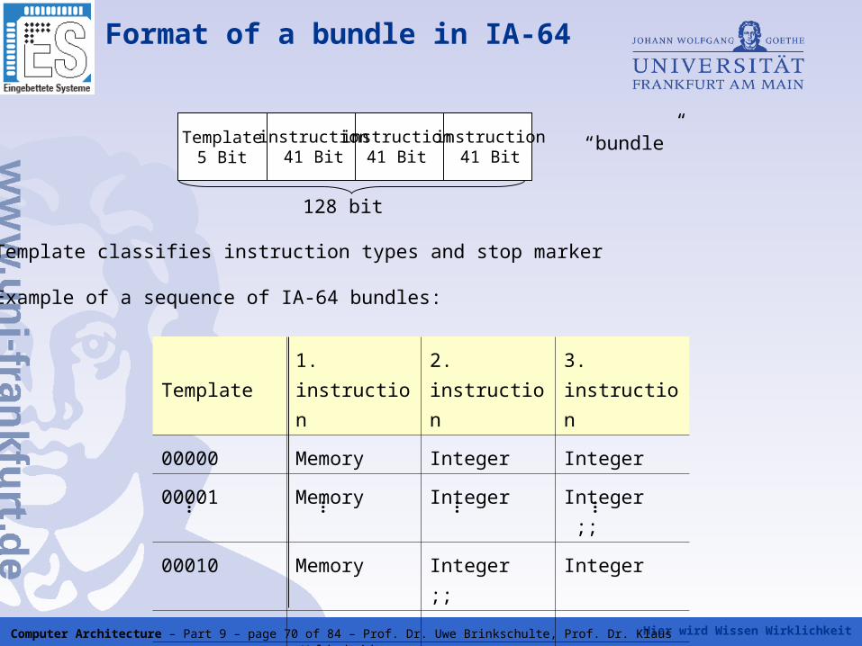
Template5 Bit
instruction41 Bit
instruction41 Bit
instruction41 Bit
Template classifies instruction types and stop marker
Example of a sequence of IA-64 bundles:
Template 1. instruction 2. instruction 3. instruction
00000 Memory Integer Integer
00001 Memory Integer Integer ;;
00010 Memory Integer ;; Integer
11101 Memory FP Branch
11110 Memory FP Branch ;;
… … … …
128 bit
“bundle”
Format of a bundle in IA-64
Hier wird Wissen Wirklichkeit Computer Architecture – Part 9 – page 71 of 84 – Prof. Dr. Uwe Brinkschulte, Prof. Dr. Klaus Waldschmidt
Itanium Processor
• Six times EPIC processor with a ten stage pipeline
• Nine execution units: four ALU/MMX units, two floating point units and three branch units
• Itanium concatenates up to two bundles of indepenent instructions and executes these instructions in parallel in the pipeline
• Future EPIC processors are able to concatenate more then two bundles
=> in contrast to VLIW scaling is possible
• Itanium 2 nearly identical to Itanium, removes some weaknesses (long cache latencies, faster bus, better X86 emulation)
• Variants of Itanium 2: McKinley (first Itanium 2), Madison (higher clock frequency then Madison), Deerfield (low power version)
• Montecito is a multicore processor containing two Itanium 2 processor cores
Hier wird Wissen Wirklichkeit Computer Architecture – Part 9 – page 72 of 84 – Prof. Dr. Uwe Brinkschulte, Prof. Dr. Klaus Waldschmidt
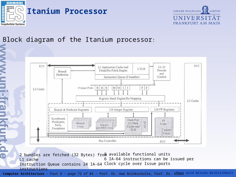
Block diagram of the Itanium processor:
2 bundles are fetched (32 Bytes) from L1 cacheInstruction Queue contains 24 IA-64 instructions
9 available functional units6 IA-64 instructions can be issued perClock cycle over Issue ports
Itanium Processor
Hier wird Wissen Wirklichkeit Computer Architecture – Part 9 – page 73 of 84 – Prof. Dr. Uwe Brinkschulte, Prof. Dr. Klaus Waldschmidt
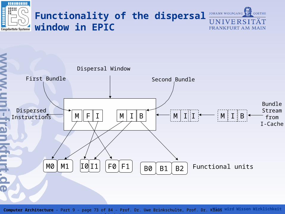
Functionality of the dispersal window in EPIC
M F I M I B M I I M I B
BundleStream
fromI-Cache
Dispersal Window
First Bundle Second Bundle
DispersedInstructions
M0 M1 I1 B2B1B0F1F0I0 Functional units
Hier wird Wissen Wirklichkeit Computer Architecture – Part 9 – page 74 of 84 – Prof. Dr. Uwe Brinkschulte, Prof. Dr. Klaus Waldschmidt
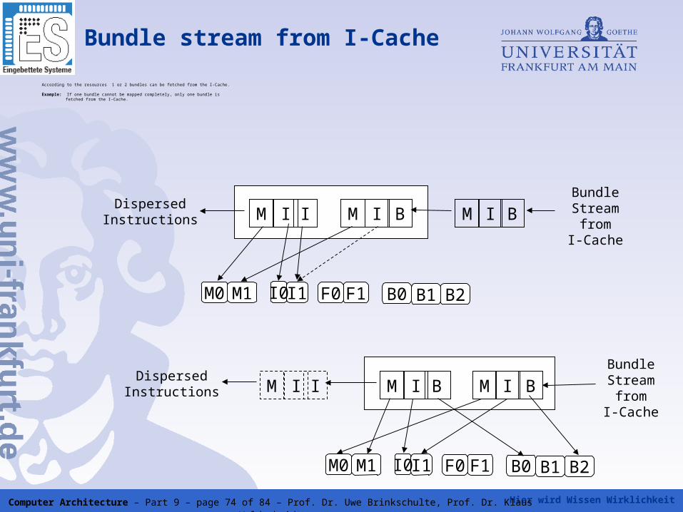
Bundle stream from I-Cache
According to the resources 1 or 2 bundles can be fetched from the I-Cache.
Example: If one bundle cannot be mapped completely, only one bundle is fetched from the I-Cache.
M I I M I B M I BBundleStream
fromI-Cache
DispersedInstructions
M0 M1 I1 B2B1B0F1F0I0
M BI M I BBundleStream
fromI-Cache
DispersedInstructions
M0 M1 I1 B2B1B0F1F0I0
M I I
Hier wird Wissen Wirklichkeit Computer Architecture – Part 9 – page 75 of 84 – Prof. Dr. Uwe Brinkschulte, Prof. Dr. Klaus Waldschmidt
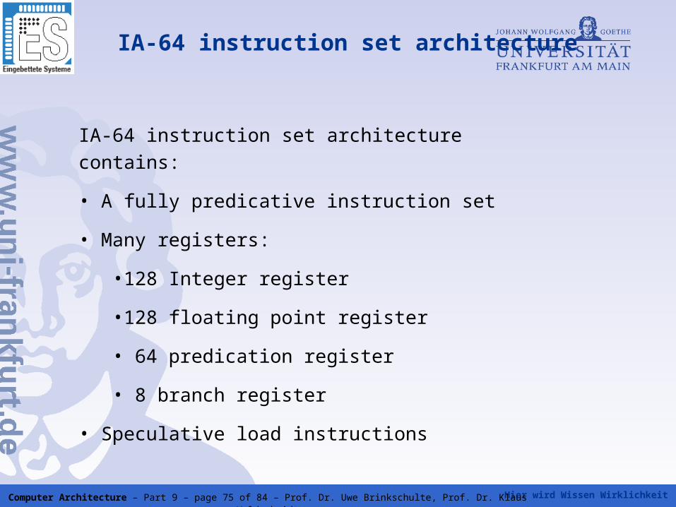
IA-64 instruction set architecture
IA-64 instruction set architecture contains:
• A fully predicative instruction set
• Many registers:
•128 Integer register
•128 floating point register
• 64 predication register
• 8 branch register
• Speculative load instructions
Hier wird Wissen Wirklichkeit Computer Architecture – Part 9 – page 76 of 84 – Prof. Dr. Uwe Brinkschulte, Prof. Dr. Klaus Waldschmidt
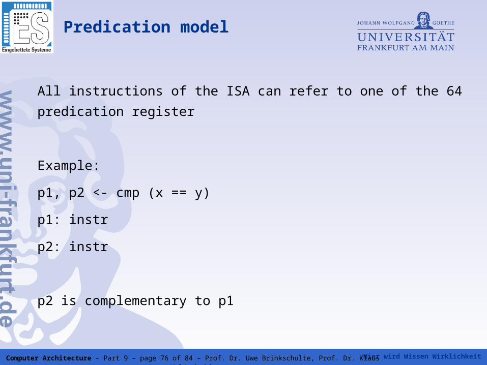
Predication model
All instructions of the ISA can refer to one of the 64 predication register
Example:
p1, p2 <- cmp (x == y)
p1: instr
p2: instr
p2 is complementary to p1
Hier wird Wissen Wirklichkeit Computer Architecture – Part 9 – page 77 of 84 – Prof. Dr. Uwe Brinkschulte, Prof. Dr. Klaus Waldschmidt
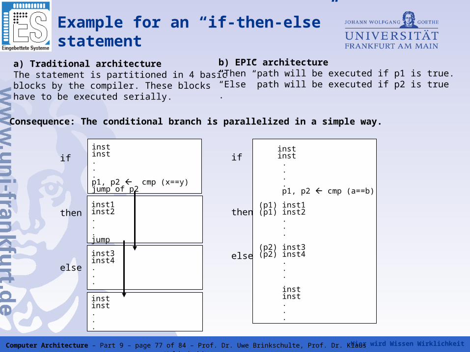
a) Traditional architectureThe statement is partitioned in 4 basicblocks by the compiler. These blockshave to be executed serially.
instinst...p1, p2 cmp (x==y)jump of p2
inst1inst2...jump
inst3inst4...
instinst...
if
then
else
if
then
else
inst inst . . . . p1, p2 cmp (a==b)
(p1) inst1(p1) inst2 . . .
(p2) inst3(p2) inst4 . . .
inst inst . . .
Example for an “if-then-else” statement
b) EPIC architecture“Then” path will be executed if p1 is true.“Else” path will be executed if p2 is true.
Consequence: The conditional branch is parallelized in a simple way.
Hier wird Wissen Wirklichkeit Computer Architecture – Part 9 – page 78 of 84 – Prof. Dr. Uwe Brinkschulte, Prof. Dr. Klaus Waldschmidt
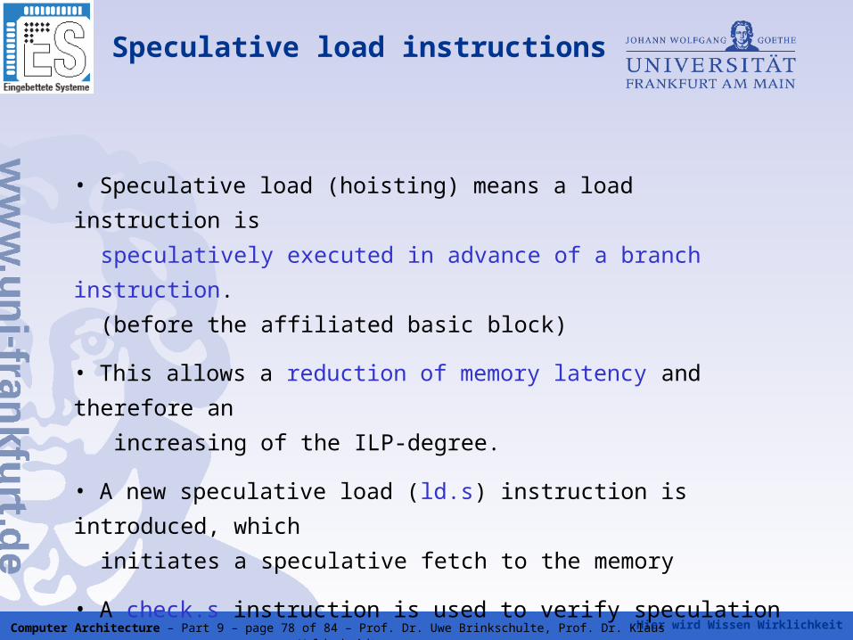
Speculative load instructions
• Speculative load (hoisting) means a load instruction is
speculatively executed in advance of a branch instruction.
(before the affiliated basic block)
• This allows a reduction of memory latency and therefore an
increasing of the ILP-degree.
• A new speculative load (ld.s) instruction is introduced, which
initiates a speculative fetch to the memory
• A check.s instruction is used to verify speculation
Hier wird Wissen Wirklichkeit Computer Architecture – Part 9 – page 79 of 84 – Prof. Dr. Uwe Brinkschulte, Prof. Dr. Klaus Waldschmidt
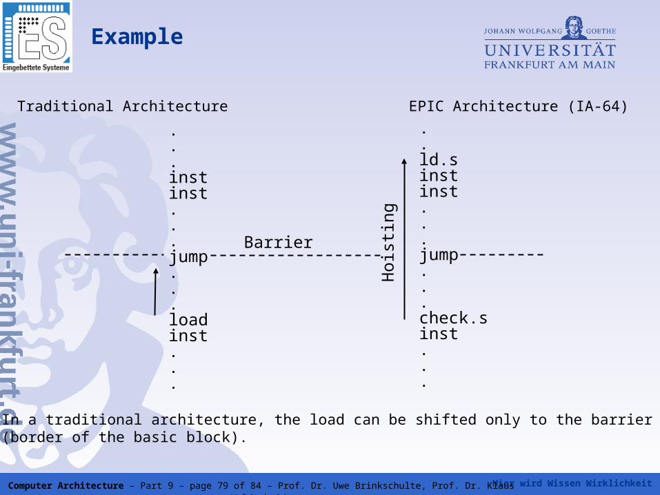
Traditional Architecture EPIC Architecture (IA-64)
.
.
.instinst...jump...loadinst...
.
.ld.sinstinst...jump...check.sinst...
Hoi
stin
g
Barrier
Example
In a traditional architecture, the load can be shifted only to the barrier (border of the basic block).
Hier wird Wissen Wirklichkeit Computer Architecture – Part 9 – page 80 of 84 – Prof. Dr. Uwe Brinkschulte, Prof. Dr. Klaus Waldschmidt
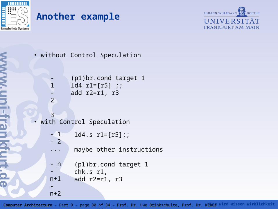
Another example
• without Control Speculation
• with Control Speculation
- 1- 2- 3
(p1)br.cond target 1 ld4 r1=[r5] ;; add r2=r1, r3
- 1- 2...
- n- n+1- n+2
ld4.s r1=[r5];;
maybe other instructions
(p1)br.cond target 1 chk.s r1, add r2=r1, r3
Hier wird Wissen Wirklichkeit Computer Architecture – Part 9 – page 81 of 84 – Prof. Dr. Uwe Brinkschulte, Prof. Dr. Klaus Waldschmidt
Comparing superscaler, VLIW and EPIC
• All three techniques aim to improve performance by concurrent execution units
• Ideally, as many instructions as execution units are present should be executed in one clock cycle
• Architecture- versus microarchitecture approach:
• VLIW and EPIC are architecture approaches
• Superscaler is a microarchitecture approach
• Instruction scheduling and conflict avoidance:
• VLIW/EPIC: the compiler schedules the assignment of instructions to execution units and takes care to avoid conflicts
• In a superscalar processor, this is done by hardware
=> VLIW/EPIC puts higher demands on the compiler than superscaler
Hier wird Wissen Wirklichkeit Computer Architecture – Part 9 – page 82 of 84 – Prof. Dr. Uwe Brinkschulte, Prof. Dr. Klaus Waldschmidt
Comparing superscaler, VLIW and EPIC
• Compiler optimization:• all three techniques require an optimizing compiler• the VLIW and EPIC compiler additionally has to take in account memory access time• superscaler memory access is managed by the load-/store-unit• often the same optimization strategies can be used in all three cases
• Instruction ordering:• a superscaler processor feeds its execution units from a single simple
execution stream• a VLIW processor uses a instruction stream of instruction packages (tuples of simple instructions)• EPIC can bundle dependent instructions. Template bits have to be checked by the processor. Several bundles of independent instructions can be executed concurrently. Therefore EPIC is a hybrid
of superscaler and VLIW
Hier wird Wissen Wirklichkeit Computer Architecture – Part 9 – page 83 of 84 – Prof. Dr. Uwe Brinkschulte, Prof. Dr. Klaus Waldschmidt
Comparing superscaler, VLIW and EPIC
• Reaction to runtime events: VLIW not as flexible as superscaler
• Memory organization: superscaler can support memory hierarchies much better then VLIW
• Branch prediction and speculation:
• dynamic branch prediction is a standard technique in current superscaler processors
• impossible in VLIW, hard to realize in EPIC
• Code density
• VLIW has a fixed instruction format => code density is lower then in superscaler processors, if the available instruction level parallelism is insufficient to fill the VLIW instruction package
• EPIC doesn't have this drawback, but the template bits produce some
overhead
Hier wird Wissen Wirklichkeit Computer Architecture – Part 9 – page 84 of 84 – Prof. Dr. Uwe Brinkschulte, Prof. Dr. Klaus Waldschmidt
Comparing superscaler, VLIW and EPIC
• Reachable performance and fields of application
• comparable performance of all three techniques under ideal conditions
• The simplicity of VLIW processors allow a higher clock frequency compared to superscaler
• VLIW is preferable for code with a high degree of parallelism, e.g. for signal processing
• General purpose applications like e.g. text processing, compiler or games have a lower degree of parallelism and a higher degree of dynamics thus favoring superscaler
• EPIC combines VLIW and superscaler thus avoiding the inelasticity of
VLIW and the issue complexity of superscaler