Embed Size (px)
Citation preview
February 2017 DocID18080 Rev 7 1/19
This is information on a product in full production. www.st.com
SPV1040
High efficiency solar battery charger with embedded MPPT
Datasheet - production data
Features 0.3 V to 5.5 V operating input voltage
140 mΩ internal synchronous rectifier
120 mΩ internal power active switch
100 kHz fixed PWM frequency
Duty cycle controlled by MPPT algorithm
Output voltage regulation, overcurrent and overtemperature protection
Input source reverse polarity protection
Built-in soft-start
Up to 95% efficiency
TSSOP8 package 3x4.4 mm
Applications Smart phones and GPS systems
Wireless headsets
Small appliances, sensors
Portable media players
Digital still cameras
Toys and portable healthcare
Description The SPV1040 device is a low power, low voltage, monolithic step-up converter with an input voltage range from 0.3 V to 5.5 V, capable of maximizing the energy generated by a single solar cell (or fuel cell), where low input voltage handling capability is extremely important. Thanks to the embedded MPPT algorithm, even under varying environmental conditions (such as irradiation, dirt, temperature) the SPV1040 offers maximum efficiency in terms of power harvested from the cells and transferred to the output. The device employs an input voltage regulation loop, which fixes the charging battery voltage via a resistor divider. The maximum output current is set with a current sense resistor according to charging current requirements. The SPV1040 protects itself and other application devices by stopping the PWM switching if either the maximum current threshold (up to 1.8 A) is reached or the maximum temperature limit (up to 155 °C) is exceeded. An additional built-in feature of the SPV1040 is the input source reverse polarity protection, which prevents damage in case of reverse connection of the solar panel on the input.
Table 1: Device summary
Order code Package Packing
SPV1040T TSSOP8
Tube
SPV1040TTR Tape and reel
TSSOP8

Contents SPV1040
2/19 DocID18080 Rev 7
Contents
1 Block diagram .................................................................................. 5
2 Pin description ................................................................................ 6
3 Electrical ratings ............................................................................. 7
4 Electrical characteristics ................................................................ 8
5 Typical characteristics .................................................................. 10
6 Detailed description ...................................................................... 12
6.1 Soft-start mode ................................................................................ 12
6.2 Start-up mode ................................................................................. 12
6.3 MPPT mode .................................................................................... 12
6.4 Constant voltage regulation ............................................................ 12
6.5 Constant current regulation ............................................................. 12
6.6 Overcurrent protection .................................................................... 13
6.7 Overtemperature protection ............................................................ 13
6.8 Shutdown mode .............................................................................. 13
6.9 Undervoltage lockout ...................................................................... 13
6.10 Reverse polarity .............................................................................. 13
6.11 Burst mode ...................................................................................... 14
6.12 Sleep-in mode ................................................................................. 14
7 Package information ..................................................................... 15
7.1 TSSOP8 package information ......................................................... 15
7.2 TSSOP8 packing information .......................................................... 17
8 Revision history ............................................................................ 18
SPV1040 List of tables
DocID18080 Rev 7 3/19
List of tables
Table 1: Device summary ........................................................................................................................... 1 Table 2: Pin description .............................................................................................................................. 6 Table 3: Absolute maximum ratings ........................................................................................................... 7 Table 4: Thermal data ................................................................................................................................. 7 Table 5: Electrical characteristics ............................................................................................................... 8 Table 6: TSSOP8 package mechanical data ............................................................................................ 16 Table 7: Document revision history .......................................................................................................... 18

List of figures SPV1040
4/19 DocID18080 Rev 7
List of figures
Figure 1: Block diagram .............................................................................................................................. 5 Figure 2: Simplified application circuit ........................................................................................................ 5 Figure 3: Pin connection top view ............................................................................................................... 6 Figure 4: Efficiency vs output voltage 3 PV cells - Vmp = 1.5 V, LX = 33 μH .......................................... 10 Figure 5: MPPT efficiency vs output voltage 3 PV cells - Vmp = 1.5 V, LX = 33 μH ................................ 10 Figure 6: Efficiency vs output voltage 4 PV cells - Vmp = 1.5 V, LX = 33 μH .......................................... 10 Figure 7: MPPT efficiency vs output voltage 4 PV cells - Vmp = 2 V, LX = 33 μH ................................... 10 Figure 8: Efficiency vs output voltage 5 PV cells - Vmp = 1.5 V, LX = 33 μH .......................................... 11 Figure 9: MPPT efficiency vs output voltage 5 PV cells - Vmp = 2.5 V, LX = 33 μH ................................ 11 Figure 10: VLX and ILX waveforms - D = 39% ......................................................................................... 11 Figure 11: VLX and ILX waveforms - D = 68% ......................................................................................... 11 Figure 12: MPPT working principle ........................................................................................................... 13 Figure 13: TSSOP8 package outline ........................................................................................................ 15 Figure 14: TSSOP8 carrier tape outline.................................................................................................... 17 Figure 15: TSSOP8 reel outline ................................................................................................................ 17

SPV1040 Block diagram
DocID18080 Rev 7 5/19
1 Block diagram Figure 1: Block diagram
Figure 2: Simplified application circuit
In order to set up the application and simulate the related test results please go to www.st.com.

Pin description SPV1040
6/19 DocID18080 Rev 7
2 Pin description Table 2: Pin description
Pin Name Type Description
1 MPP-SET I Non-inverting input to sense the PV cell voltage. It cannot be left floating.
2 GND Ground Power ground reference.
8 XSHUT I
Shutdown input pin: XSHUT = low, the device in power off mode.
XSHUT = high, the device is enabled for operating mode. This pin cannot be left floating.
3 LX I Booster inductor connection.
7 ICTRL_PLUS I Non-inverting input of constant current control loop. It cannot be left floating.
6 ICTRL_MINUS I Inverting input of constant current control loop. It cannot be left floating.
5 VCTRL I Inverting input of constant current control loop. It cannot be left floating.
4 VOUT O Booster output voltage.
Figure 3: Pin connection top view

SPV1040 Electrical ratings
DocID18080 Rev 7 7/19
3 Electrical ratings Table 3: Absolute maximum ratings
Symbol Parameter Value Unit
MPP-SET Analog input [-5.5, VOUT]
V
GND Ground 0
XSHUT Analog input [-5.5, VOUT]
LX Analog input [-5.5, VOUT]
ICTRL_PLUS Analog input [-0.3, VOUT]
ICTRL_MINUS Analog input [-0.3, VOUT]
VCTRL Analog input [-0.3, VOUT]
VOUT Analog output [-0.3, 5.5]
Table 4: Thermal data
Symbol Parameter Value Unit
Rthj-amb Thermal resistance, junction-to-ambient 135 °C/W
Tjop Junction operating temperature -40 to 125 °C
Tstg Storage temperature -40 to 150 °C
RthJA has been measured on a 2-layer PCB: FR4, 35 μm Cu thickness, 2.8 cm2

Electrical characteristics SPV1040
8/19 DocID18080 Rev 7
4 Electrical characteristics
VMPP-SET = 0.5 V, VCTRL = Ictrl+ = Ictrl- = GND, XSHUT = 0.5 V, TJ = -40 °C to 125 °C, unless otherwise specified.
Table 5: Electrical characteristics
Symbol Parameter Test conditions Min. Typ. Max. Unit
Input source section
VMPP-SET Low boost voltage threshold VOUT = 3.3 V 0.4 0.45 0.50 V
Iq Quiescent current
ILOAD = 0 mA,
VCTRL = 2 V,
VOUT = 3.3 V
60 80
µA ISD Shutdown current
VOUT = 3.3 V,
VCTRL = 2 V,
ILOAD = 0 mA,
XSHUT = GND
0.7 5
Irev Reverse input source current VMPP-SET = -4 V,
VOUT = 1.5 V 1 5
VUVLO
Undervoltage lockout
threshold for turn ON
@VOUT = 3.3 V
VMPP-SET increasing
0.27 0.34
V Undervoltage lockout
threshold for turn OFF
@VOUT = 3.3 V
VMPP-SET decreasing 0.14 0.24
Power section
RDS(on)-N N-channel power switch ON
resistance 120
mΩ
RDS(on)-P P-channel synchronous
rectifier ON resistance VCTRL = 2 V
140
Control section
VMPPT-THR MPPT-mode threshold VOUT increasing,
VMPP-SET = 1.5 V 1.7 1.8 2 V
VOUT Output voltage range VMPP-SET ≥ 1.5 V 2
5.2(1) V
POUT(2) Maximum output power VMPP-SET ≥ 1.5 V
3 W
ILX Maximum inductor current
peak 1.5 1.65 1.8 A
FPWM PWM signal frequency
70 100 130 kHz
VREF Internal VCTRL reference
voltage
VOUT ≥ 1.8 V,
VCTRL increasing 1.2 1.25 1.3 V
VICTRL Sensing current offset ICTRL+ - ICTRL-
decreasing 40 50 60 mV
XSHUT XSHUT logic low XSHUT increasing
0.27 0.34
V XSHUT logic High XSHUT decreasing 0.14 0.24
Thermal shutdown

SPV1040 Electrical characteristics
DocID18080 Rev 7 9/19
Symbol Parameter Test conditions Min. Typ. Max. Unit
Tshutdown
Overtemperature threshold
for turn OFF
Temperature
increasing 155
°C
Overtemperature threshold
for turn ON
Temperature
decreasing 130
Notes:
(1)According to the absolute maximum ratings the output charge voltage cannot be above 4.8 V but if a higher
VOUT up to 5.2 V is needed, a Schottky diode must be placed between the Lx and VOUT pins as shown in
Figure 2. In such way the Schottky diode in parallel to the embedded P-channel MOSFET reduces the voltage drop between the VLX pin and the VOUT pin determined by the body diode when the internal PMOS is OFF from 0.7 V down to 0.3 V. (2)Given Tj = Ta + RthJA x PD, and assuming RthJA = 135 °C/W, and that in order to avoid device destruction Tjmax
must be ≤ 125 °C, and that in the worst conditions TA = 85 °C, the power dissipated inside the device is given by:
PD ≤ TJ-TA/RthJA=295 mW. Therefore, if in the worst case the efficiency is assumed to be 90%, then PIN-MAX = 3.3
W and POUT-MAX = 3 W.

Typical characteristics SPV1040
10/19 DocID18080 Rev 7
5 Typical characteristics
Figure 4: Efficiency vs output voltage 3 PV cells - Vmp = 1.5 V, LX = 33 μH
Figure 5: MPPT efficiency vs output voltage 3 PV cells - Vmp = 1.5 V, LX = 33 μH
Figure 6: Efficiency vs output voltage 4 PV cells - Vmp = 1.5 V, LX = 33 μH
Figure 7: MPPT efficiency vs output voltage 4 PV cells - Vmp = 2 V, LX = 33 μH

SPV1040 Typical characteristics
DocID18080 Rev 7 11/19
Figure 8: Efficiency vs output voltage 5 PV cells - Vmp = 1.5 V, LX = 33 μH
Figure 9: MPPT efficiency vs output voltage 5 PV cells - Vmp = 2.5 V, LX = 33 μH
Figure 10: VLX and ILX waveforms - D = 39%
Figure 11: VLX and ILX waveforms - D = 68%
Detailed description SPV1040
12/19 DocID18080 Rev 7
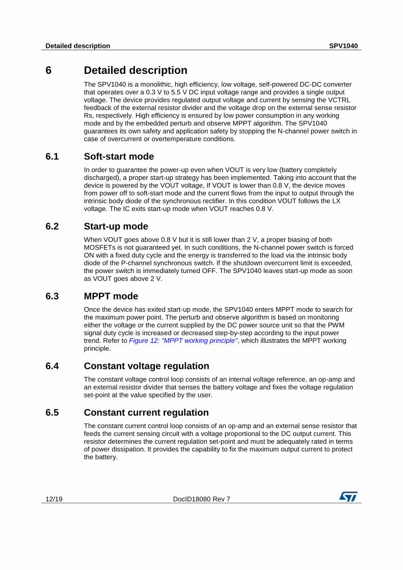
6 Detailed description
The SPV1040 is a monolithic, high efficiency, low voltage, self-powered DC-DC converter that operates over a 0.3 V to 5.5 V DC input voltage range and provides a single output voltage. The device provides regulated output voltage and current by sensing the VCTRL feedback of the external resistor divider and the voltage drop on the external sense resistor Rs, respectively. High efficiency is ensured by low power consumption in any working mode and by the embedded perturb and observe MPPT algorithm. The SPV1040 guarantees its own safety and application safety by stopping the N-channel power switch in case of overcurrent or overtemperature conditions.
6.1 Soft-start mode
In order to guarantee the power-up even when VOUT is very low (battery completely discharged), a proper start-up strategy has been implemented. Taking into account that the device is powered by the VOUT voltage, If VOUT is lower than 0.8 V, the device moves from power off to soft-start mode and the current flows from the input to output through the intrinsic body diode of the synchronous rectifier. In this condition VOUT follows the LX voltage. The IC exits start-up mode when VOUT reaches 0.8 V.
6.2 Start-up mode
When VOUT goes above 0.8 V but it is still lower than 2 V, a proper biasing of both MOSFETs is not guaranteed yet. In such conditions, the N-channel power switch is forced ON with a fixed duty cycle and the energy is transferred to the load via the intrinsic body diode of the P-channel synchronous switch. If the shutdown overcurrent limit is exceeded, the power switch is immediately turned OFF. The SPV1040 leaves start-up mode as soon as VOUT goes above 2 V.
6.3 MPPT mode
Once the device has exited start-up mode, the SPV1040 enters MPPT mode to search for the maximum power point. The perturb and observe algorithm is based on monitoring either the voltage or the current supplied by the DC power source unit so that the PWM signal duty cycle is increased or decreased step-by-step according to the input power trend. Refer to Figure 12: "MPPT working principle", which illustrates the MPPT working principle.
6.4 Constant voltage regulation
The constant voltage control loop consists of an internal voltage reference, an op-amp and an external resistor divider that senses the battery voltage and fixes the voltage regulation set-point at the value specified by the user.
6.5 Constant current regulation
The constant current control loop consists of an op-amp and an external sense resistor that feeds the current sensing circuit with a voltage proportional to the DC output current. This resistor determines the current regulation set-point and must be adequately rated in terms of power dissipation. It provides the capability to fix the maximum output current to protect the battery.

SPV1040 Detailed description
DocID18080 Rev 7 13/19
6.6 Overcurrent protection
When the current that flows through the inductor reaches 1.8 A (overcurrent shutdown limit), the N-channel power switch is immediately forced OFF and the P-channel synchronous rectifier is switched ON. Once the overcurrent condition has expired (the inductor current goes below 1.8 A) the N-channel power switch is turned back ON.
6.7 Overtemperature protection
When the temperature sensed at silicon level reaches 155 °C (overtemperature shutdown limit), the N-channel power switch is immediately forced OFF and the P-channel synchronous rectifier is switched ON. The device becomes operative again as soon as the silicon temperature goes below 130 °C.
6.8 Shutdown mode
The XSHUT pin low shuts OFF all internal circuitry, achieving the lowest power consumption mode.
6.9 Undervoltage lockout
In order to prevent batteries from over-discharging, the device turns OFF in case of MPPSET voltage is lower than 0.24 V (no irradiation). A hysteresis has been implemented to avoid unpredictable ON-OFF switching.
6.10 Reverse polarity
In order to avoid damage to the device and battery discharge when the solar panel connection is reverse-inserted, a dedicated protection circuit has been implemented. In such condition, the SPV1040 stays OFF until the panel is inserted correctly.
Figure 12: MPPT working principle

Detailed description SPV1040
14/19 DocID18080 Rev 7
6.11 Burst mode
When the output voltage reaches the battery charge voltage, the MPP-SET voltage drops below 450 mV, or the output current reaches the output maximum current limit, the duty cycle D drops down to 10% and the device evolves from operating mode to burst mode. The converter no longer works at constant frequency, but at frequencies gradually lower (1 TON over 1 PWM cycle, 1 TON over 2 PWM cycles, …,1 TON over 16 PWM cycles) prior to entering sleep-in mode.
6.12 Sleep-in mode
Once sleep-in mode has been entered, no current is provided to the load. The device exits this mode once the cause, which forced it into this state, is no longer present.

SPV1040 Package information
DocID18080 Rev 7 15/19
7 Package information
In order to meet environmental requirements, ST offers these devices in different grades of ECOPACK® packages, depending on their level of environmental compliance. ECOPACK® specifications, grade definitions and product status are available at: www.st.com. ECOPACK® is an ST trademark.
7.1 TSSOP8 package information
Figure 13: TSSOP8 package outline

Package information SPV1040
16/19 DocID18080 Rev 7
Table 6: TSSOP8 package mechanical data
Dim. mm
Min. Typ. Max.
A
1.20
A1 0.05
0.15
A2 0.80 1.00 1.05
b 0.19
0.30
c 0.09
0.20
D 2.90 3.00 3.10
E 6.20 6.40 6.60
E1 4.30 4.40 4.50
e
0.65
L 0.45 0.60 0.75
L1
1.00
L2
0.25
k 0
8
aaa
0.10
Dimensions D does not include mold flash or protrusions. Mold flash or protrusions do not exceed 0.15 mm per side.
Dimension E1 does not include interlead flash or protrusions. Interlead flash or protrusions do not exceed 0.25 mm per side.

SPV1040 Package information
DocID18080 Rev 7 17/19
7.2 TSSOP8 packing information
Figure 14: TSSOP8 carrier tape outline
Figure 15: TSSOP8 reel outline

Revision history SPV1040
18/19 DocID18080 Rev 7
8 Revision history Table 7: Document revision history
Date Revision Changes
08-Oct-2010 1 First release.
06-Apr-2011 2 Updated the cover page, DFN8 information deleted, Chapter 3,
Chapter 4 and Chapter 6.
04-Oct-2011 3 – Updated Figure 1, Figure 2, Table 2 and Table 5
– Minor text changes.
25-Jul-2012 4 Updated Figure 4, Figure 5, Figure 6, Figure 7, Figure 8, and Figure
9.
21-Mar-2013 5 Updated Figure 1 and note 1 in Table 5.
26-Sep-2016 6 Added Section 7.2: "Packing information".
06-Feb-2017 7 Update Section 7.1: "TSSOP8 package information"

SPV1040
DocID18080 Rev 7 19/19
IMPORTANT NOTICE – PLEASE READ CAREFULLY
STMicroelectronics NV and its subsidiaries (“ST”) reserve the right to make changes, corrections, enhancements, modifications , and improvements to ST products and/or to this document at any time without notice. Purchasers should obtain the latest relevant information on ST products before placing orders. ST products are sold pursuant to ST’s terms and conditions of sale in place at the time of order acknowledgement.
Purchasers are solely responsible for the choice, selection, and use of ST products and ST assumes no liability for application assistance or the design of Purchasers’ products.
No license, express or implied, to any intellectual property right is granted by ST herein.
Resale of ST products with provisions different from the information set forth herein shall void any warranty granted by ST for such product.
ST and the ST logo are trademarks of ST. All other product or service names are the property of their respective owners.
Information in this document supersedes and replaces information previously supplied in any prior versions of this document.
© 2017 STMicroelectronics – All rights reserved