Embed Size (px)
Citation preview
UPTEC IT 08 007
Examensarbete 30 hpJuni 2008
High Performance Industrial Diagnostic Systems
Leon Ljunggren


Teknisk- naturvetenskaplig fakultet UTH-enheten Besöksadress: Ångströmlaboratoriet Lägerhyddsvägen 1 Hus 4, Plan 0 Postadress: Box 536 751 21 Uppsala Telefon: 018 – 471 30 03 Telefax: 018 – 471 30 00 Hemsida: http://www.teknat.uu.se/student
Abstract
High Performance Industrial Diagnostic Systems
Leon Ljunggren
CC-Systems has developed a diagnostic system used to monitor the operation ofcrane-spreaders, called Diagnostics Runtime Engine (DRE). The system monitorssignals from the spreaders’ control system and performs different actions whenneeded. The system can for example send an e-mail to an operator if a problemoccurs. The control system is implemented in a softPLC named CoDeSys. A softPLCis a kind of virtual machine for running PLC programs on a normal computer, whilethe diagnostic system is a normal computer program that runs under the hostoperating system. The system is currently operational and in use, but there have beenconcerns with the system’s ability of performing well under a large signal load,preventing it from being used in large systems. Tests have shown that a large amountof time is spent copying signals from the control system in the virtual machine to thediagnostic system that runs directly under the host operating system.In this Master’s Thesis a new design for the diagnostic system was developed andimplemented as a prototype under the name CoDeSys Diagnostics Runtime Engine(CODRE). This new design eliminated the need of copying signals from the controlsystem and thus allowed for much better scaling. Testing showed that CODRE wascapable of handling almost twice as many signals as DRE within the same timeconstraints.
Tryckt av: Reprocentralen ITC ISSN: 1401-5749, UPTEC IT 08 007Examinator: Anders JanssonÄmnesgranskare: Justin PearsonHandledare: Carl-Magnus Moon

2 (46)
Examensarbetare
Leon Ljunggren Dok Nr
1.3 Säk klass
Handledare Carl-Magnus Moon
Datum
Datum Rev
PA1 Filnamn Report - HPIDS.doc
High Performance Industrial Diagnostic Systems
sssssssSySystems
SAMMANFATTNING CC-Systems har utvecklat ett system för diagnostik av lyftok vilket används aktivt inom industrin idag. Systemet har till uppgift att övervaka signaler från ett kontrollsystem och, om det behövs, utföra diverse uppgifter baserat på signalerna. Exempelvis så kan systemet skicka ett meddelande via e-post om problem uppstår. Kontrollsystemet körs under en softPLC, vilket är en virtuell maskin som gör det möjligt att köra PLC program på en vanlig dator, medan diagnossystemet är ett vanligt program som körs direkt under operativsystemet. Systemet är i aktivt bruk men det har visat sig att det har problem med att hantera en större signalmängd, vilket gör det svårt att bygga större system. Tester har visat att en mycket stor del av tiden går åt till att kopiera signaler från kontrollsystemet i softPLC:n till diagnostiksystemet. I detta examensarbete har det tagits fram en ny systemarkitektur som eliminerar behovet av att kopiera signaler från softPLC:n till diagnostiksystemet. Detta uppnåddes genom att implementera delar av diagnostiksystemet direkt i softPLC:n. För att bevisa att den nya arkitekturen kan hantera en större mängd signaler än den gamla så implementerades den i en prototyp som ställdes mot det gamla systemet i en serie tester. Det visade sig att det nya systemet var kapabelt att hantera nästan dubbelt så många signaler på samma tid.

3 (46)
Examensarbetare
Leon Ljunggren Dok Nr
1.3 Säk klass
Handledare Carl-Magnus Moon
Datum
Datum Rev
PA1 Filnamn Report - HPIDS.doc
High Performance Industrial Diagnostic Systems
sssssssSySystems
4 (46)
Examensarbetare
Leon Ljunggren Dok Nr
1.3 Säk klass
Handledare Carl-Magnus Moon
Datum
Datum Rev
PA1 Filnamn Report - HPIDS.doc
High Performance Industrial Diagnostic Systems
sssssssSySystems
CONTENT
1 Background ........................................................................................................................ 8
1.1 Problem Description.................................................................................................... 8
1.2 Goals and Purpose....................................................................................................... 9
1.3 Limitations ................................................................................................................... 9
1.4 Disposition ................................................................................................................... 9
2 Background Studies ......................................................................................................... 12
2.1 CoDeSys..................................................................................................................... 12 2.1.1 IEC 61131-3 Languages .................................................................................... 13 2.1.2 Continuous Function Chart ................................................................................ 14 2.1.3 Program Organization Unit................................................................................ 15 2.1.4 Tasks .................................................................................................................. 16 2.1.5 Extending the Runtime Functionality ................................................................ 16
2.2 Diagnostic Runtime Engine ....................................................................................... 17 2.2.1 Design ................................................................................................................ 18 2.2.2 Runtime Program............................................................................................... 19 2.2.3 Runtime Behaviour ............................................................................................ 19 2.2.4 DABE – Configuration Utility........................................................................... 19
2.3 CC Pilot XS................................................................................................................ 20
3 Design and Models ........................................................................................................... 22
3.1 Goals .......................................................................................................................... 22
3.2 General Design .......................................................................................................... 22
3.3 Thread Model............................................................................................................. 24 3.3.1 Thread Hazards .................................................................................................. 25
3.4 Class Model of the Runtime Extension ...................................................................... 26
3.5 Communication Interface........................................................................................... 27
4 CODRE – CoDeSys Diagnostic Runtime Engine.......................................................... 28
4.1 Implementation .......................................................................................................... 28
4.2 Features ..................................................................................................................... 30
4.3 Limitations ................................................................................................................. 30
4.4 Discussion and Conclusions ...................................................................................... 30
5 Performance ..................................................................................................................... 32
5.1 Test Implementation................................................................................................... 32
5 (46)
Examensarbetare
Leon Ljunggren Dok Nr
1.3 Säk klass
Handledare Carl-Magnus Moon
Datum
Datum Rev
PA1 Filnamn Report - HPIDS.doc
High Performance Industrial Diagnostic Systems
sssssssSySystems
5.2 Result.......................................................................................................................... 34 5.2.1 Overall Performance and Scaling ...................................................................... 34 5.2.2 Block performance............................................................................................. 37
5.3 Discussion and Conclusion........................................................................................ 39
6 Discussion.......................................................................................................................... 40
7 Conclusion ........................................................................................................................ 42
8 Glossary ............................................................................................................................ 44
9 References ......................................................................................................................... 46
6 (46)
Examensarbetare
Leon Ljunggren Dok Nr
1.3 Säk klass
Handledare Carl-Magnus Moon
Datum
Datum Rev
PA1 Filnamn Report - HPIDS.doc
High Performance Industrial Diagnostic Systems
sssssssSySystems
ACKNOWLEDGMENTS I would like to thank CC-Systems in general and Carl-Magnus Moon in particular for the opportunity to write my Master’s Thesis with them and for the help and support I received. I would also like to thank Daniel Odervång and Robin Sving for helping me proof reading. Last but not least I would like to thank my counsellor at the university, Justin Pearson.

7 (46)
Examensarbetare
Leon Ljunggren Dok Nr
1.3 Säk klass
Handledare Carl-Magnus Moon
Datum
Datum Rev
PA1 Filnamn Report - HPIDS.doc
High Performance Industrial Diagnostic Systems
sssssssSySystems
8 (46)
Examensarbetare
Leon Ljunggren Dok Nr
1.3 Säk klass
Handledare Carl-Magnus Moon
Datum
Datum Rev
PA1 Filnamn Report - HPIDS.doc
High Performance Industrial Diagnostic Systems
sssssssSySystems
1 BACKGROUND
Cross Country Systems AB (CC-Systems) works on control and information solutions for machines operating in rough environments. They develop both hardware and software solutions, usually tailored to fit the customers’ needs. One of the company’s primary products is their line of small, rugged computers meant to operate in heavy-duty industrial environments. Among their customers are John Deere, Atlas Copco and Bromma Conquip.1 One of their projects is the development of a diagnostic system for spreaders (used mainly in harbours for lifting containers) called Diagnostic Runtime Engine (DRE). This tool, along with the control system developed in cooperation with the customer, is run on rugged computers provided by CC-Systems and performs real time monitoring of the spreaders’ operation. DRE monitors the control system by reading the signal values that the control system operates on and can take several different actions based on this information. If it, for example, detects a wire break it can raise an alarm and even directly notify a live operator using e-mail or by sending a message, using the Short Messaging Service (SMS). For less serious events, for example a lift being completed, there are other actions such as logging the event to a database or creating a trend or statistics. The system also keeps a so called black box that logs the 1 000 last signal changes so that, in the event of a major breakdown, the cause of the error can be found. The system is in operation at the customer and performs its current tasks as intended. However, it has shown to be unable to scale to work with larger systems that have more signals that need to be monitored. Tests have shown that the inability to scale to larger systems comes mostly from having to copy signals from the control system to the diagnostic system, as is needed with the current design. In this Master’s Thesis I will develop a new design that eliminates the need to perform signal copying and by doing so improve the scalability of the system.
1.1 Problem Description
As mentioned above the main reason for DRE’s inability to scale to larger systems seem to be the need to copy signals from the control system to the diagnostic system. The reason why this is needed is that the control system and the diagnostic system are implemented in different environments. The control system is run on a software based Programmable Logic Computer (PLC). A PLC is a non general-purpose digital computer. It is specifically designed for handling input and output in industrial environments, for example they can often be found controlling an assembly line in a factory. A software-based PLC, a softPLC, is a software program that emulates a PLC’s behaviour (a virtual machine), making it possible to use a general purpose computer, such as a normal PC or a pocketPC, as a PLC. The softPLC used for the control system is called CoDeSys, which also comes with a complete development environment specially tailored for developing control systems. For example it supports several different graphical programming languages that make it easy to illustrate control circuits for input and output.
1 CC-Systems About Us, 2008-04-17, http://www.cc-systems.com

9 (46)
Examensarbetare
Leon Ljunggren Dok Nr
1.3 Säk klass
Handledare Carl-Magnus Moon
Datum
Datum Rev
PA1 Filnamn Report - HPIDS.doc
High Performance Industrial Diagnostic Systems
sssssssSySystems
While the control system is run inside a virtual machine the diagnostic system is a normal computer program that runs directly under the host operating system, which in this case is Windows CE. It is this that makes it necessary to copy signals from the virtual machine and into the diagnostic system. This can take quite a bit of time, several milliseconds for a few hundred signals, and is a large factor in preventing the system from scaling. A design which eliminates the need to perform this copying of signals would thus be able to scale much better. This could be achieved by implementing the diagnostic system in CoDeSys, allowing it to be run in the same softPLC as the control system. Another potential advantage with a new design would be integration of the components into one product rather than many separate. Currently the diagnostic system needs a custom made editor called the Diagnostic Application Builder Environment (DABE) in order to be configured. If the system were implemented in CoDeSys, using one of the graphical programming languages, this editor could be eliminated.
1.2 Goals and Purpose
The main goal of this thesis is to create a design for the diagnostic system that allows it to be integrated with the control system in such a way as to eliminate the need of copying signals. The design should allow for better scaling while at the same time remain compatible with the interface of the old design (database structure, events etc). This would make it possible to replace it without having to change any Graphical User Interface (GUI) or other services that may be dependent on it. Other goals with the new design are to provide one complete system that can be configured completely in CoDeSys without the need of using custom tools, and also to improve the communication between different threads in the system. Once the design is complete it will be implemented in a prototype and then evaluated against the old system in terms of performance.
1.3 Limitations
The prototype created from the design does not need to be feature complete. It should implement only the features needed to provide proof of concept. The design on the other hand should be so complete that it would be possible to implement an operational system without significant changes.
1.4 Disposition
The first chapter of this reports aims to explain the background of the Master’s Thesis and is required reading if one is to understand the overall goal of the project. The second chapter deals with important background information that can be useful for the reader, but is not essential. In the third and forth chapter of the report the new system design and its implementation is explained. This part of the report is aimed for those looking for information on how the new design and prototype work. Chapter five deals with testing the performance of the new system compared to the old. For anyone interested in a deeper understanding of the results this chapter is essential reading. However, it is possible to get a simple overview of the results by only reading chapter seven.

10 (46)
Examensarbetare
Leon Ljunggren Dok Nr
1.3 Säk klass
Handledare Carl-Magnus Moon
Datum
Datum Rev
PA1 Filnamn Report - HPIDS.doc
High Performance Industrial Diagnostic Systems
sssssssSySystems
The report is best read in chronological order from chapter one through seven, but it is possible to skip everything but chapter one and seven if so desired.

11 (46)
Examensarbetare
Leon Ljunggren Dok Nr
1.3 Säk klass
Handledare Carl-Magnus Moon
Datum
Datum Rev
PA1 Filnamn Report - HPIDS.doc
High Performance Industrial Diagnostic Systems
sssssssSySystems
12 (46)
Examensarbetare
Leon Ljunggren Dok Nr
1.3 Säk klass
Handledare Carl-Magnus Moon
Datum
Datum Rev
PA1 Filnamn Report - HPIDS.doc
High Performance Industrial Diagnostic Systems
sssssssSySystems
2 BACKGROUND STUDIES
2.1 CoDeSys
CoDeSys is a softPLC but also a complete development environment consisting of an editor, a compiler and a debugger. CoDeSys comes with extensive documentation where “User Manual for PLC Programming with CoDeSys 2.3” 2 is the most important one. Unless otherwise stated the information in this chapter comes from the aforementioned document. As mentioned in the previous chapter, a PLC (Programmable Logic Controller) is a non general-purpose digital computer that is designed for use in industrial automation. A PLC is generally designed to withstand extreme temperatures, a high degree of moist and other hazards. A PLC is considered to be a real-time system, meaning that results must be produced in a bounded time3. There is a set of standard languages described in IEC 61131-3 that makes it possible to write unified code for different PLCs4. A softPLC is a virtual machine, a piece of software that makes it possible to run PLC programs on a general-purpose computer, such as an ordinary PC or a smart phone. This can be an advantage since it allows for greater flexibility in hardware while it at the same time remains compatible with old code. CoDeSys consists of two parts; the runtime softPLC and the development environment. The runtime is a separate program that is usually run as a service; this is the part that acts as the PLC. In order to download code into the softPLC the user connects to it via a network (in case the softPLC is run on the same computer as the development environment then it will connect to the local host), or directly via a serie-port, using the development environment. It is also possible to use this connection for debugging. When connected, while a program is running, the user will be able to get a near real time view of the state of the system (including variable values, current code that is being executed etc). As with all modern debuggers it is possible to perform a number of tasks such as step into, step over, set break points etc.
2 3S – Smart Software Solutions, 2007, User Manual for PLC Programming with CoDeSys 2.3
3 Liu, Layland, Association for Computing Machinery, 1973, Scheduling Algorithms for
Multiprogramming in a Hard-Real-Time Environment
4 Tiegelkamp, John, Springer, 2001, IEC 61131-3: programming Industrial Automation
Systems
13 (46)
Examensarbetare
Leon Ljunggren Dok Nr
1.3 Säk klass
Handledare Carl-Magnus Moon
Datum
Datum Rev
PA1 Filnamn Report - HPIDS.doc
High Performance Industrial Diagnostic Systems
sssssssSySystems
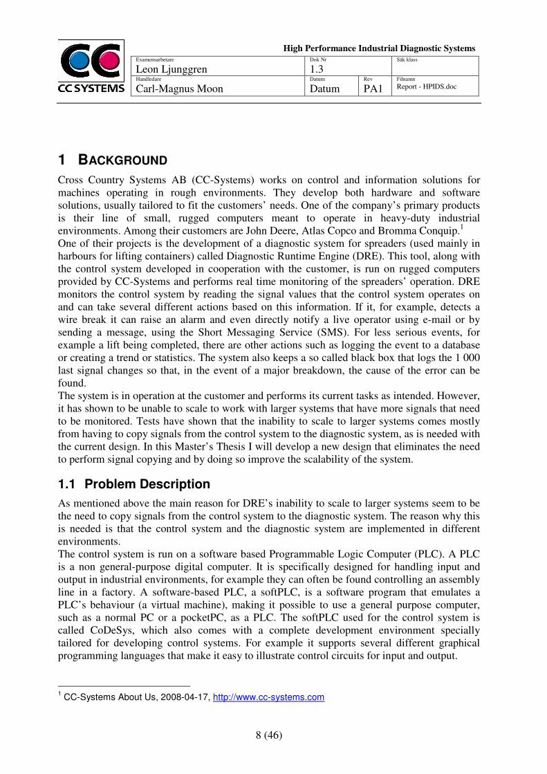
Figure 1 - CoDeSys's Editor
2.1.1 IEC 61131-3 Languages
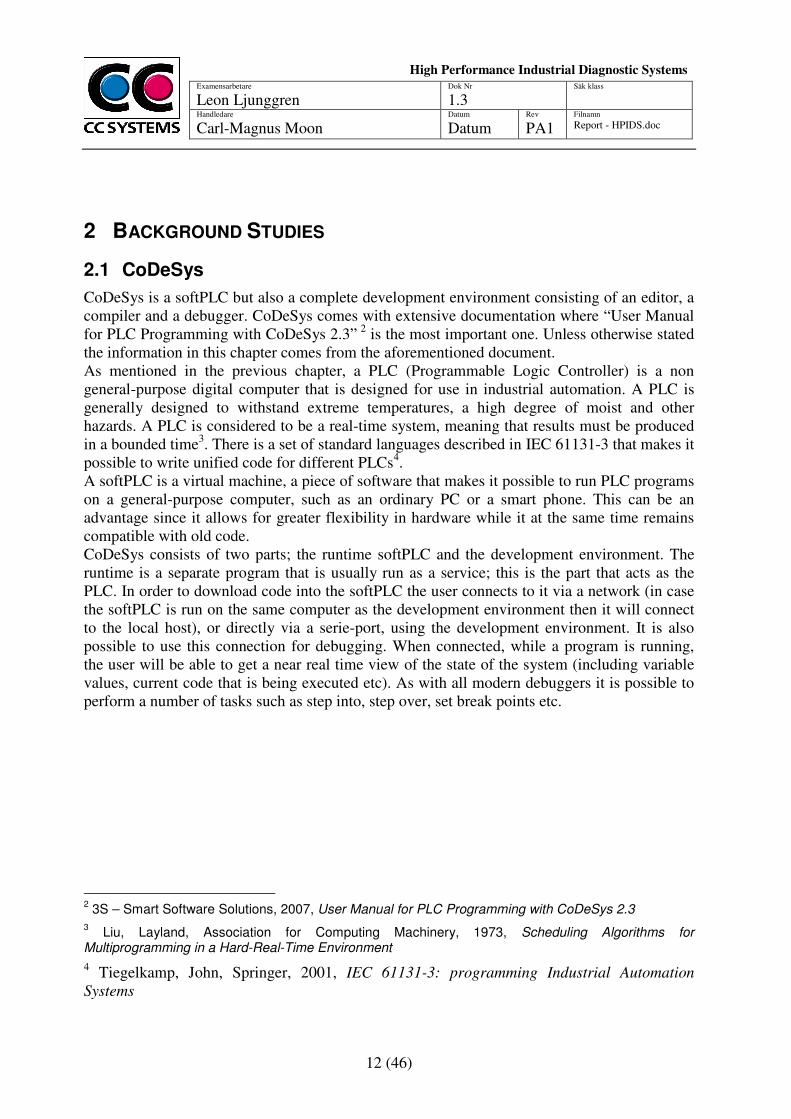
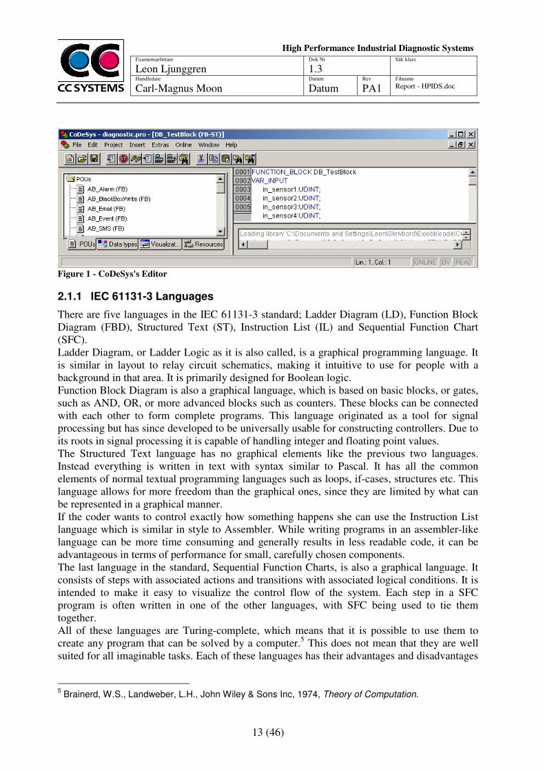
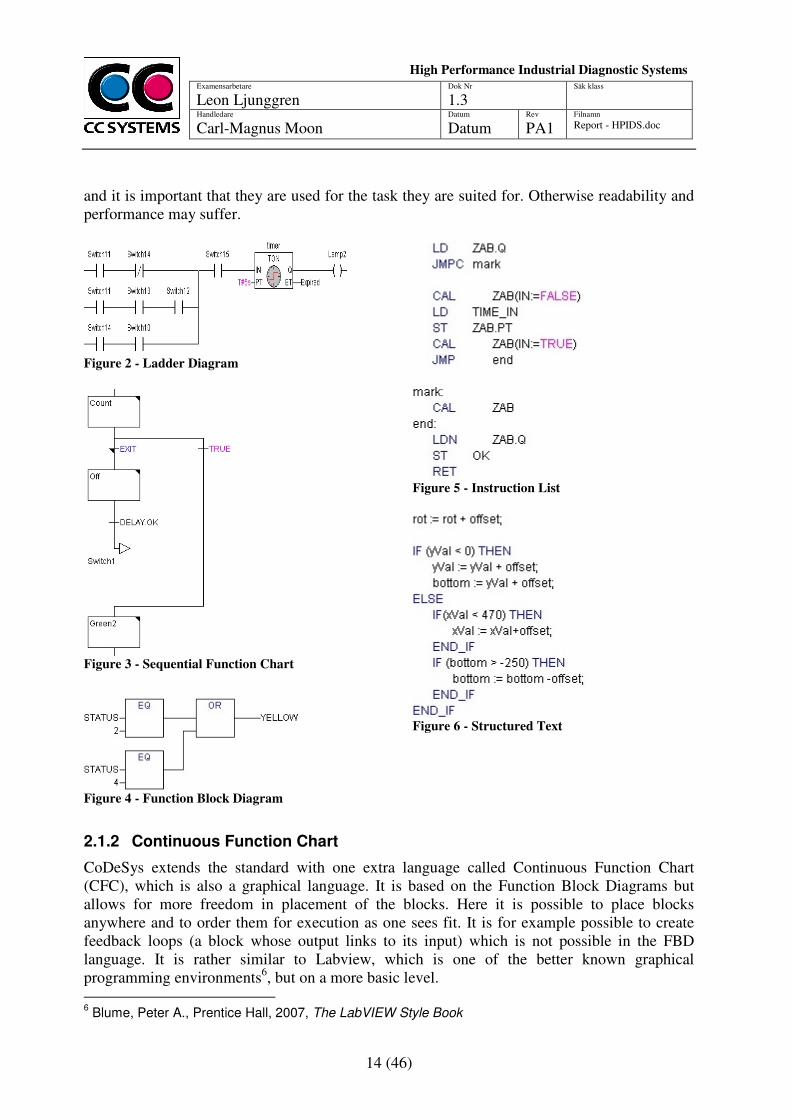
There are five languages in the IEC 61131-3 standard; Ladder Diagram (LD), Function Block Diagram (FBD), Structured Text (ST), Instruction List (IL) and Sequential Function Chart (SFC). Ladder Diagram, or Ladder Logic as it is also called, is a graphical programming language. It is similar in layout to relay circuit schematics, making it intuitive to use for people with a background in that area. It is primarily designed for Boolean logic. Function Block Diagram is also a graphical language, which is based on basic blocks, or gates, such as AND, OR, or more advanced blocks such as counters. These blocks can be connected with each other to form complete programs. This language originated as a tool for signal processing but has since developed to be universally usable for constructing controllers. Due to its roots in signal processing it is capable of handling integer and floating point values. The Structured Text language has no graphical elements like the previous two languages. Instead everything is written in text with syntax similar to Pascal. It has all the common elements of normal textual programming languages such as loops, if-cases, structures etc. This language allows for more freedom than the graphical ones, since they are limited by what can be represented in a graphical manner. If the coder wants to control exactly how something happens she can use the Instruction List language which is similar in style to Assembler. While writing programs in an assembler-like language can be more time consuming and generally results in less readable code, it can be advantageous in terms of performance for small, carefully chosen components. The last language in the standard, Sequential Function Charts, is also a graphical language. It consists of steps with associated actions and transitions with associated logical conditions. It is intended to make it easy to visualize the control flow of the system. Each step in a SFC program is often written in one of the other languages, with SFC being used to tie them together. All of these languages are Turing-complete, which means that it is possible to use them to create any program that can be solved by a computer.5 This does not mean that they are well suited for all imaginable tasks. Each of these languages has their advantages and disadvantages
5 Brainerd, W.S., Landweber, L.H., John Wiley & Sons Inc, 1974, Theory of Computation.
14 (46)
Examensarbetare
Leon Ljunggren Dok Nr
1.3 Säk klass
Handledare Carl-Magnus Moon
Datum
Datum Rev
PA1 Filnamn Report - HPIDS.doc
High Performance Industrial Diagnostic Systems
sssssssSySystems
and it is important that they are used for the task they are suited for. Otherwise readability and performance may suffer.
Figure 2 - Ladder Diagram
Figure 3 - Sequential Function Chart
Figure 4 - Function Block Diagram
Figure 5 - Instruction List
Figure 6 - Structured Text
2.1.2 Continuous Function Chart
CoDeSys extends the standard with one extra language called Continuous Function Chart (CFC), which is also a graphical language. It is based on the Function Block Diagrams but allows for more freedom in placement of the blocks. Here it is possible to place blocks anywhere and to order them for execution as one sees fit. It is for example possible to create feedback loops (a block whose output links to its input) which is not possible in the FBD language. It is rather similar to Labview, which is one of the better known graphical programming environments6, but on a more basic level. 6 Blume, Peter A., Prentice Hall, 2007, The LabVIEW Style Book
15 (46)
Examensarbetare
Leon Ljunggren Dok Nr
1.3 Säk klass
Handledare Carl-Magnus Moon
Datum
Datum Rev
PA1 Filnamn Report - HPIDS.doc
High Performance Industrial Diagnostic Systems
sssssssSySystems
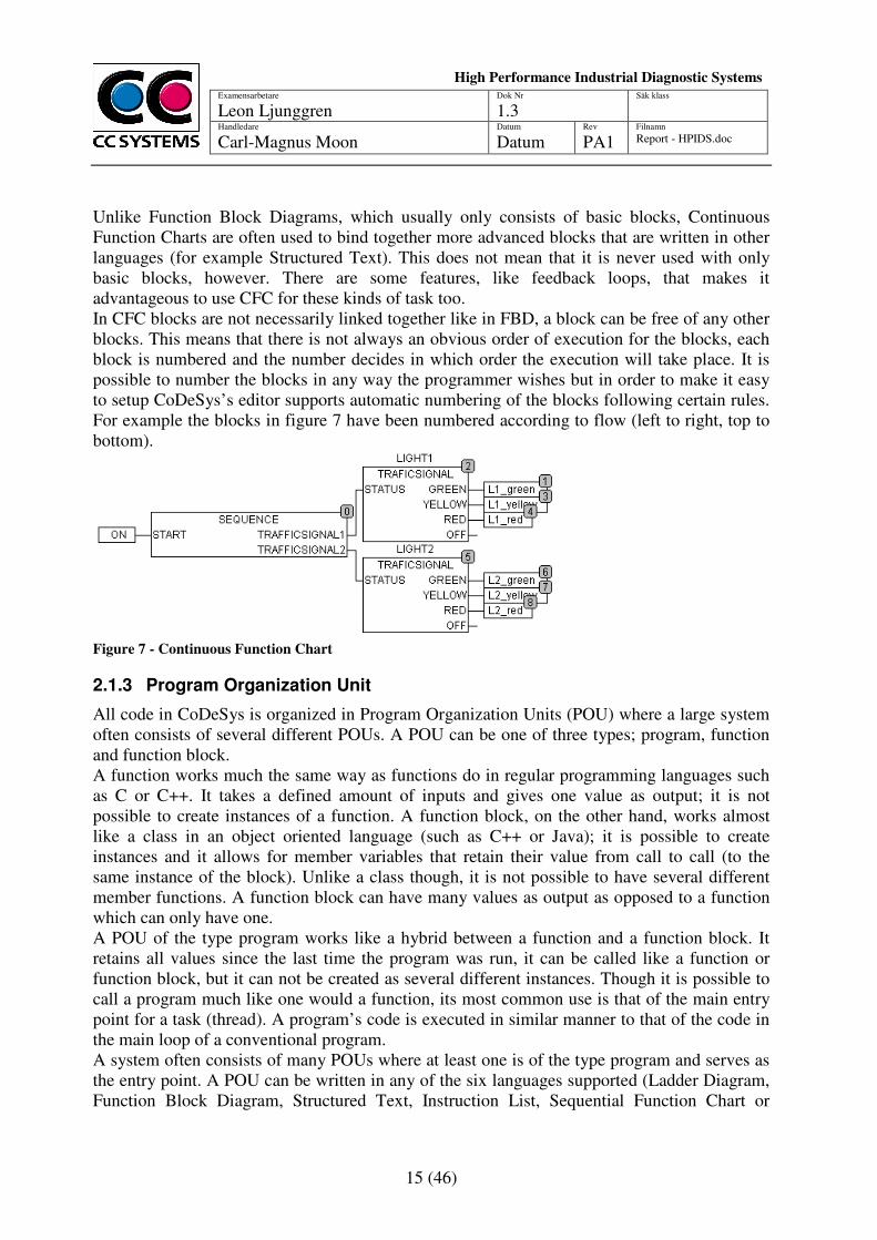
Unlike Function Block Diagrams, which usually only consists of basic blocks, Continuous Function Charts are often used to bind together more advanced blocks that are written in other languages (for example Structured Text). This does not mean that it is never used with only basic blocks, however. There are some features, like feedback loops, that makes it advantageous to use CFC for these kinds of task too. In CFC blocks are not necessarily linked together like in FBD, a block can be free of any other blocks. This means that there is not always an obvious order of execution for the blocks, each block is numbered and the number decides in which order the execution will take place. It is possible to number the blocks in any way the programmer wishes but in order to make it easy to setup CoDeSys’s editor supports automatic numbering of the blocks following certain rules. For example the blocks in figure 7 have been numbered according to flow (left to right, top to bottom).
Figure 7 - Continuous Function Chart
2.1.3 Program Organization Unit
All code in CoDeSys is organized in Program Organization Units (POU) where a large system often consists of several different POUs. A POU can be one of three types; program, function and function block. A function works much the same way as functions do in regular programming languages such as C or C++. It takes a defined amount of inputs and gives one value as output; it is not possible to create instances of a function. A function block, on the other hand, works almost like a class in an object oriented language (such as C++ or Java); it is possible to create instances and it allows for member variables that retain their value from call to call (to the same instance of the block). Unlike a class though, it is not possible to have several different member functions. A function block can have many values as output as opposed to a function which can only have one. A POU of the type program works like a hybrid between a function and a function block. It retains all values since the last time the program was run, it can be called like a function or function block, but it can not be created as several different instances. Though it is possible to call a program much like one would a function, its most common use is that of the main entry point for a task (thread). A program’s code is executed in similar manner to that of the code in the main loop of a conventional program. A system often consists of many POUs where at least one is of the type program and serves as the entry point. A POU can be written in any of the six languages supported (Ladder Diagram, Function Block Diagram, Structured Text, Instruction List, Sequential Function Chart or

16 (46)
Examensarbetare
Leon Ljunggren Dok Nr
1.3 Säk klass
Handledare Carl-Magnus Moon
Datum
Datum Rev
PA1 Filnamn Report - HPIDS.doc
High Performance Industrial Diagnostic Systems
sssssssSySystems
Continuous Function Chart), allowing the programmer to choose the language that best fits that particular part of the system.
2.1.4 Tasks
It is possible to use multiple threads, or tasks as it is called in CoDeSys, in one system. The CoDeSys runtime has a custom designed runtime scheduler for handling these tasks. This is to ensure that it acts like a real-time system even when it is running on non real-time operating systems. There is no hard limit on how many tasks that can be used but there are only 32 different priority levels (0-31). Compared to other systems like Windows CE that has 256 priority levels this can seem like a small number, but it is usually more than enough for these kinds of systems. Each task will have a program associated with it that it will call when it is time for execution. The execution time is dependent on the type of the task. A task can be one of four different types: cyclic, freewheeling, triggered by event and triggered by external event. A cyclic task will try to maintain a set cycle time, it will execute the program attached to it and then sleep until the cycle time is up and it is time to execute again. A freewheeling task is not concerned with cycle times, but will instead just execute the next iteration as soon as the previous one has completed. A task that is triggered by an event will execute when a set variable goes high while a task that is triggered by an external event will execute based on a system event (supported events vary depending on the target platform). Each task can have a watchdog attached. A watchdog is a routine that monitors the task and if it takes longer than it should to execute it will raise an error. This way it is possible to detect, and if needed, restart a task that stalls during execution.
2.1.5 Extending the Runtime Functionality
It is possible to extend the functionality of the CoDeSys 32-bit runtime by providing the new functionality in a Dynamically Linked Library (DLL) that will be loaded during the runtime’s start up.7 In order to access the new functionality from a CoDeSys program a so called external library has to be prepared. This library contains function and type declarations that have to correspond to those defined in the DLL file. Almost any functionality that can be coded into a DLL can be added to the runtime this way. Although, the most common use of the extension abilities is drivers for different devices or services (databases for example). The DLL containing the extensions has to be able to run natively on the target device. This means that the coder needs to be aware of the target’s specifications and makes sure only to use features that is supported by this target (a common thing to miss is the bit order, endian, of the target system, which will cause big problems if not taken care of correctly). This means that it is harder to maintain code for many different targets, unlike in CoDeSys where a standard program will run on most target devices.
7 3S – Smart Software Solutions, 2008, CoDeSys SP 32 Bit Full Multitasking Runtime System for 32-Bit
Processors
17 (46)
Examensarbetare
Leon Ljunggren Dok Nr
1.3 Säk klass
Handledare Carl-Magnus Moon
Datum
Datum Rev
PA1 Filnamn Report - HPIDS.doc
High Performance Industrial Diagnostic Systems
sssssssSySystems
2.2 Diagnostic Runtime Engine
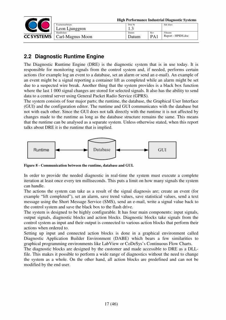
The Diagnostic Runtime Engine (DRE) is the diagnostic system that is in use today. It is responsible for monitoring signals from the control system and, if needed, performs certain actions (for example log an event to a database, set an alarm or send an e-mail). An example of an event might be a signal reporting a container lift as completed while an alarm might be set due to a suspected wire break. Another thing that the system provides is a black box function where the last 1 000 signal changes are stored for selected signals. It also has the ability to send data to a central server using General Packet Radio Service (GPRS). The system consists of four major parts; the runtime, the database, the Graphical User Interface (GUI) and the configuration editor. The runtime and GUI communicates with the database but not with each other. Since the GUI does not talk directly with the runtime it is not affected by changes made to the runtime as long as the database structure remains the same. This means that the runtime can be analysed as a separate system. Unless otherwise stated, when this report talks about DRE it is the runtime that is implied.
Figure 8 - Communication between the runtime, database and GUI.
In order to provide the needed diagnostic in real-time the system must execute a complete iteration at least once every ten milliseconds. This puts a limit on how many signals the system can handle. The actions the system can take as a result of the signal diagnosis are; create an event (for example “lift completed”), set an alarm, save trend values, save statistical values, send a text message using the Short Message Service (SMS), send an e-mail, write a signal value back to the control system and save the black box to the flash drive. The system is designed to be highly configurable. It has four main components: input signals, output signals, diagnostic blocks and action blocks. Diagnostic blocks take signals from the control system as input and their output is connected to various action blocks that perform their actions when ordered to. Setting up input and connected action blocks is done in a graphical environment called Diagnostic Application Builder Environment (DABE) which bears a few similarities to graphical programming environments like LabView or CoDeSys’s Continuous Flow Charts. The diagnostic blocks are designed by the customer and made accessible to DRE as a DLL-file. This makes it possible to perform a wide range of diagnostics without the need to change the system as a whole. On the other hand, all action blocks are predefined and can not be modified by the end user.

18 (46)
Examensarbetare
Leon Ljunggren Dok Nr
1.3 Säk klass
Handledare Carl-Magnus Moon
Datum
Datum Rev
PA1 Filnamn Report - HPIDS.doc
High Performance Industrial Diagnostic Systems
sssssssSySystems
2.2.1 Design
The control system and DRE are two separate entities; the control system runs in the CoDeSys runtime while DRE runs independently as a normal program. The two can communicate through an API provided by CoDeSys. Since the programs are run independently of each other there is no way to guarantee that all signals that DRE receives are from the same cycle of the control system. Yet, this is not a problem since the control system itself receives signals in a similar manner, from a distributed set of sensors. There is no way to guarantee that a signal from a certain sensor will reach the control system at an exact time, so the system has been built to handle this. This means that the diagnostics can be run correctly even if it would receive signals that are from different cycles of the control system. The design consists of four layers: the signal adaptation layer, the diagnostic layer, the action layer and the system layer. The signal adaptation layer handles reading and writing of signals to and from the control system in the CoDeSys runtime and also keeps track of virtual signals that are needed for trend and statistical calculations. These signals are then passed on to the diagnostic layer that runs all diagnostic blocks using the signals provided. The action layer will then read the output from the diagnostic blocks and order the actions to be taken. These actions are put in a queue that the system layer will work through and execute them when it has time for it. There are two different kinds of threads in DRE: the main thread that does all the time critical diagnostics and the worker threads that perform the actions. There are three worker threads: one that handles writing to the database (almost all actions causes some information to be stored in the database), one that handles storage of the black box’s logs and one that handles sending messages such as e-mails and text messages (SMS).
Figure 9 - Overview of the DRE design
19 (46)
Examensarbetare
Leon Ljunggren Dok Nr
1.3 Säk klass
Handledare Carl-Magnus Moon
Datum
Datum Rev
PA1 Filnamn Report - HPIDS.doc
High Performance Industrial Diagnostic Systems
sssssssSySystems
2.2.2 Runtime Program
The runtime behaves a bit differently depending on if it is run on the CC Pilot XS or a regular computer. On a PC it assumes that the CoDeSys runtime is already started when it starts and will try to connect to it in order to read the signals. On the CC Pilot XS on the other hand, it will load the CoDeSys runtime as a DLL. The two systems will still behave as if they were separate processes except that doing it this way makes it possible to perform faster signal copying due to a, from the operating system’s perspective, shared memory area. This difference means that the PC version of DRE will have a relatively longer signal copy time than the CC Pilot XS version. Due to this any tests that compare performance between this system and another has to be performed on the CC Pilot XS or the results will be skewed. The runtime will at start up link with the DLL file that contains the diagnostic blocks and then read a configuration file to setup the system. The system is fully described by the configuration file and all memory allocations and other initialization can thus be done at this point.
2.2.3 Runtime Behaviour
The system has a set cycle time of ten milliseconds and is currently used to diagnose about 300 signals for the control system. In the event that it detects something it will execute an appropriate action. During execution the system will spend most of its time copying signals and running the diagnostic blocks, an action is only taken a few times per minute on average. This means that action execution takes up a very small part of the total execution time. However, it is important to note that actions usually come in bursts. No actions might be taken for a long period of time and then several will be ordered over a short time span (a few seconds). As a result of the layered design all actions will be ordered after all of the diagnostic blocks have been executed.
2.2.4 DABE – Configuration Utility
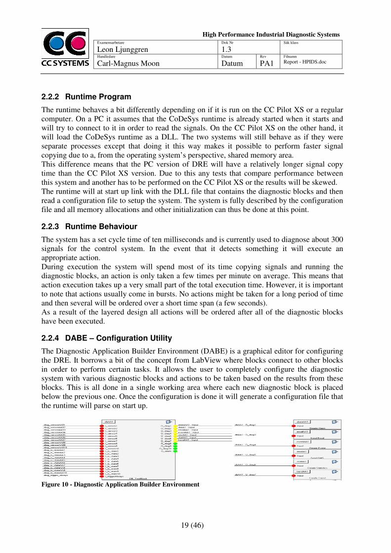
The Diagnostic Application Builder Environment (DABE) is a graphical editor for configuring the DRE. It borrows a bit of the concept from LabView where blocks connect to other blocks in order to perform certain tasks. It allows the user to completely configure the diagnostic system with various diagnostic blocks and actions to be taken based on the results from these blocks. This is all done in a single working area where each new diagnostic block is placed below the previous one. Once the configuration is done it will generate a configuration file that the runtime will parse on start up.
Figure 10 - Diagnostic Application Builder Environment
20 (46)
Examensarbetare
Leon Ljunggren Dok Nr
1.3 Säk klass
Handledare Carl-Magnus Moon
Datum
Datum Rev
PA1 Filnamn Report - HPIDS.doc
High Performance Industrial Diagnostic Systems
sssssssSySystems
2.3 CC Pilot XS
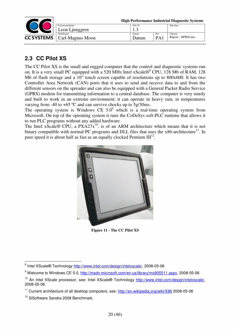
The CC Pilot XS is the small and rugged computer that the control and diagnostic systems run on. It is a very small PC equipped with a 520 MHz Intel xScale®8 CPU, 128 Mb of RAM, 128 Mb of flash storage and a 10” touch screen capable of resolutions up to 800x600. It has two Controller Area Network (CAN) ports that it uses to send and receive data to and from the different sensors on the spreader and can also be equipped with a General Packet Radio Service (GPRS) modem for transmitting information to a central database. The computer is very sturdy and built to work in an extreme environment; it can operate in heavy rain, in temperatures varying from -40 to +65 ºC and can survive chocks up to 5g/30ms. The operating system is Windows CE 5.09 which is a real-time operating system from Microsoft. On top of the operating system it runs the CoDeSys soft-PLC runtime that allows it to run PLC programs without any added hardware. The Intel xScale® CPU, a PXA27x10, is of an ARM architecture which means that it is not binary compatible with normal PC programs and DLL files that uses the x86-architecture11. In pure speed it is about half as fast as an equally clocked Pentium III12.
Figure 11 - The CC Pilot XS
8 Intel XScale® Technology http://www.intel.com/design/intelxscale/, 2008-05-06
9 Welcome to Windows CE 5.0, http://msdn.microsoft.com/en-us/library/ms905511.aspx, 2008-05-06
10 An Intel XScale processor, see: Intel XScale® Technology http://www.intel.com/design/intelxscale/,
2008-05-06
11 Current architecture of all desktop computers, see: http://en.wikipedia.org/wiki/X86 2008-05-06
12 SiSoftware Sandra 2008 Benchmark.

21 (46)
Examensarbetare
Leon Ljunggren Dok Nr
1.3 Säk klass
Handledare Carl-Magnus Moon
Datum
Datum Rev
PA1 Filnamn Report - HPIDS.doc
High Performance Industrial Diagnostic Systems
sssssssSySystems
22 (46)
Examensarbetare
Leon Ljunggren Dok Nr
1.3 Säk klass
Handledare Carl-Magnus Moon
Datum
Datum Rev
PA1 Filnamn Report - HPIDS.doc
High Performance Industrial Diagnostic Systems
sssssssSySystems
3 DESIGN AND MODELS
Part of making an efficient software system is creating a design that describes the system and this design can consist of several different models. Working with a model makes it easier to find design flaws early which in turn means less cost in terms of time and money. Once completed, the model can be used as a template when coding the system.
3.1 Goals
The main goal of the new design is to improve performance so that there is room for diagnostics of more signals than in the old system. The idea on how to achieve this is to find a design that does not require signals to be copied from the CoDeSys runtime into the DRE. Aside from performance the design must achieve the following:
1. Maintain the current database structure 2. Be compatible with the current GUI 3. Allow for easy configuration of the system using the CoDeSys editor 4. Integrate into one system 5. Support different priority levels of diagnostic 6. Reuse existing code
The first two goals are top priorities; a system that can not work with the current database and GUI would be too much work to deploy for use in the real world. While this project does not aim to create a product ready for deployment it needs to take this into consideration. Goal three and four are highly desirable since it would eliminate the need to support a custom configuration editor and allow the users to work in an environment that they are used to. The fifth goal enables running of certain diagnostic tasks on other cycle times than the standard one (ten milliseconds). However, this may not be used as a way to improve performance by running certain tasks more seldom; performance analysis must be done at the same priority level as the old system. The last goal would be nice to have; reusing code that is already tested and stable would speed up the development and deployment of the new system.
3.2 General Design
Previous tests have shown that a large portion of the cycle time of the old system is spent copying signals from the control system to the signal adaptation layer in the diagnostic system. The copy operations are done through an API that CoDeSys provides which limits the possibilities for optimization. Instead the need to copy signals out of the CoDeSys runtime will be eliminated by implementing parts of the diagnostic system directly in CoDeSys. As described in the DRE section the signal adaptation layer is responsible for reading and writing signals from the control system. This layer can be mostly eliminated by moving the diagnostic and actions layers to CoDeSys. It does also handle virtual signals such as trend and statistical signals so parts of it will still have to be kept, now as a subpart of the system layer rather than as a whole layer by itself.
23 (46)
Examensarbetare
Leon Ljunggren Dok Nr
1.3 Säk klass
Handledare Carl-Magnus Moon
Datum
Datum Rev
PA1 Filnamn Report - HPIDS.doc
High Performance Industrial Diagnostic Systems
sssssssSySystems
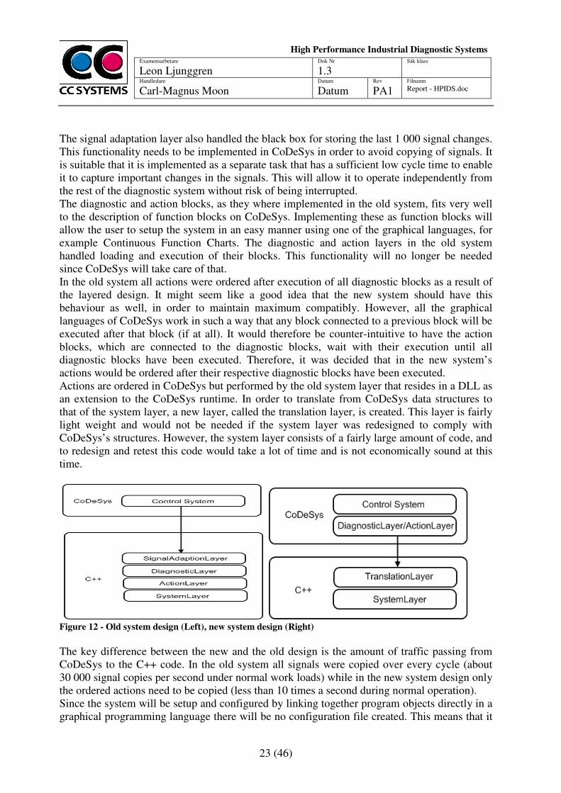
The signal adaptation layer also handled the black box for storing the last 1 000 signal changes. This functionality needs to be implemented in CoDeSys in order to avoid copying of signals. It is suitable that it is implemented as a separate task that has a sufficient low cycle time to enable it to capture important changes in the signals. This will allow it to operate independently from the rest of the diagnostic system without risk of being interrupted. The diagnostic and action blocks, as they where implemented in the old system, fits very well to the description of function blocks on CoDeSys. Implementing these as function blocks will allow the user to setup the system in an easy manner using one of the graphical languages, for example Continuous Function Charts. The diagnostic and action layers in the old system handled loading and execution of their blocks. This functionality will no longer be needed since CoDeSys will take care of that. In the old system all actions were ordered after execution of all diagnostic blocks as a result of the layered design. It might seem like a good idea that the new system should have this behaviour as well, in order to maintain maximum compatibly. However, all the graphical languages of CoDeSys work in such a way that any block connected to a previous block will be executed after that block (if at all). It would therefore be counter-intuitive to have the action blocks, which are connected to the diagnostic blocks, wait with their execution until all diagnostic blocks have been executed. Therefore, it was decided that in the new system’s actions would be ordered after their respective diagnostic blocks have been executed. Actions are ordered in CoDeSys but performed by the old system layer that resides in a DLL as an extension to the CoDeSys runtime. In order to translate from CoDeSys data structures to that of the system layer, a new layer, called the translation layer, is created. This layer is fairly light weight and would not be needed if the system layer was redesigned to comply with CoDeSys’s structures. However, the system layer consists of a fairly large amount of code, and to redesign and retest this code would take a lot of time and is not economically sound at this time.
Figure 12 - Old system design (Left), new system design (Right)
The key difference between the new and the old design is the amount of traffic passing from CoDeSys to the C++ code. In the old system all signals were copied over every cycle (about 30 000 signal copies per second under normal work loads) while in the new system design only the ordered actions need to be copied (less than 10 times a second during normal operation). Since the system will be setup and configured by linking together program objects directly in a graphical programming language there will be no configuration file created. This means that it
24 (46)
Examensarbetare
Leon Ljunggren Dok Nr
1.3 Säk klass
Handledare Carl-Magnus Moon
Datum
Datum Rev
PA1 Filnamn Report - HPIDS.doc
High Performance Industrial Diagnostic Systems
sssssssSySystems
is not possible to define actions before the system is up and running (trends, statistical values and alarms needs to be initialized in the system layer so that they are visible in the GUI). Instead these definitions will take place during the first cycle of the program. This can cause the first cycle to take longer time to execute. That can, however, be considered as part of the start up process rather than a normal cycle and does therefore not fall under the normal time constrains.
3.3 Thread Model
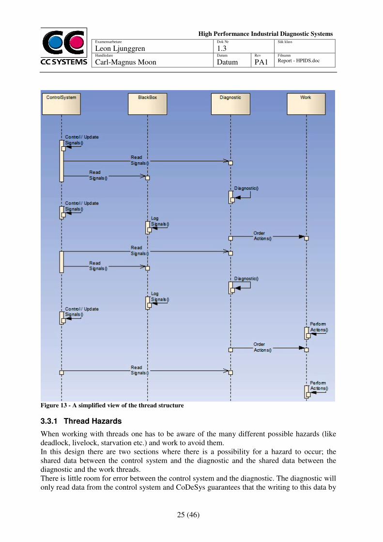
Seen as a complete system there are three different levels of threads: the control system, the diagnostic and the working threads. The control system works independently of the other threads, it has the highest priority and will execute first every cycle (with a cycle time of ten milliseconds). It will write to global variables, which the diagnostic system can read. CoDeSys guarantees that these writes will all be done before a lower priority task can read them (there is, on the other hand, no way of guaranteeing that a lower priority task will read all variables from the same cycle of the higher priority task)13. The diagnostic consists of at least one task (thread) that runs with the same cycle time as the control system but at lower priority. It is possible to add more tasks that run with lower priority and longer cycle time for less critical diagnostics. The diagnostic tasks do not share any data between them. The black box task can be seen as a special case of a diagnostic task. The thread layout of the worker threads (the system layer) remains the same as in the old system. Three threads do the work of executing queued actions, one that handles database writing, one that writes the black box to the disk and one that handles sending messages such as text messages and e-mail. Each of these threads has a queue that is shared with the diagnostic system. These queues need to be locked when inserting or removing elements, which means that one of the work threads can halt the execution of one of the diagnostic threads, but only for the time it takes to remove an element from its queue.
13
Interview with Matthias Maier, employee at 3S – Smart Software Solutions
25 (46)
Examensarbetare
Leon Ljunggren Dok Nr
1.3 Säk klass
Handledare Carl-Magnus Moon
Datum
Datum Rev
PA1 Filnamn Report - HPIDS.doc
High Performance Industrial Diagnostic Systems
sssssssSySystems
Figure 13 - A simplified view of the thread structure
3.3.1 Thread Hazards
When working with threads one has to be aware of the many different possible hazards (like deadlock, livelock, starvation etc.) and work to avoid them. In this design there are two sections where there is a possibility for a hazard to occur; the shared data between the control system and the diagnostic and the shared data between the diagnostic and the work threads. There is little room for error between the control system and the diagnostic. The diagnostic will only read data from the control system and CoDeSys guarantees that the writing to this data by
26 (46)
Examensarbetare
Leon Ljunggren Dok Nr
1.3 Säk klass
Handledare Carl-Magnus Moon
Datum
Datum Rev
PA1 Filnamn Report - HPIDS.doc
High Performance Industrial Diagnostic Systems
sssssssSySystems
the control system will be done before any reading can be done. Each read operation is in itself atomic but it is possible (but unlikely, unless the system is run at a higher than recommended load) that the reading is interrupted to give way for another cycle of the control system. If that happens the diagnostic might be run on data from several different cycles of the control system. On the other hand, the system used to gather the data (sensors on different part of the crane spreader) is in nature distributed without a common cycle time, so it is natural for signals to reach the control system at different cycles even though they were generated by the same event. Because of this it is not considered to be a problem that the diagnostic might be run on signals from different cycles of the control system, but it is something that the system administrator needs to be aware of. The other area where thread problems can occur is between the diagnostic and the worker threads. As mentioned before, each work thread has a queue that is shared with the diagnostic tasks. These queues are the means as to which a diagnostic task can order an action performed. In order to add or remove to and from a queue it has to be locked, but as long as the lock is only active over the add/remove operation and no other lock is acquired while another lock is active there is no risk of deadlock. The lower priority work thread can thus block the higher priority diagnostic task for the time it takes to remove an item from its queue, causing a priority inversion. However, the operating system which the system will be run under, Windows CE, supports priority inheritance which solves the problem by letting the work thread temporarily receive the priority of the diagnostic task until it has finished with the removal operation and releases the lock.
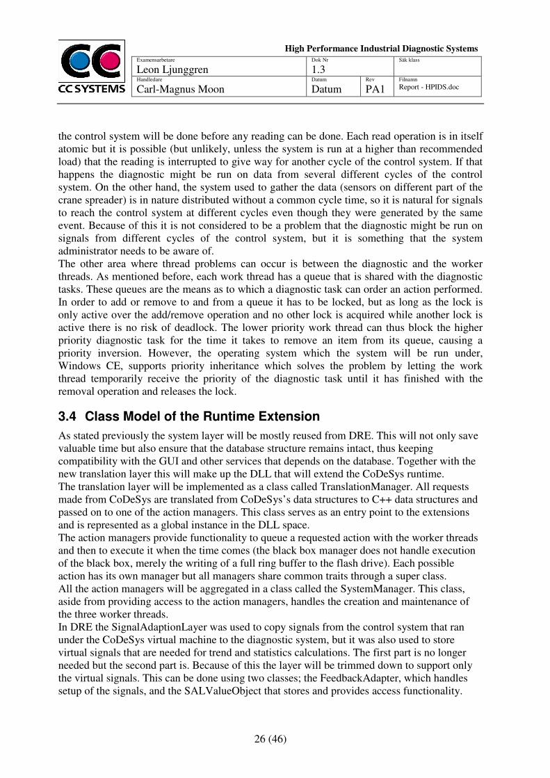
3.4 Class Model of the Runtime Extension
As stated previously the system layer will be mostly reused from DRE. This will not only save valuable time but also ensure that the database structure remains intact, thus keeping compatibility with the GUI and other services that depends on the database. Together with the new translation layer this will make up the DLL that will extend the CoDeSys runtime. The translation layer will be implemented as a class called TranslationManager. All requests made from CoDeSys are translated from CoDeSys’s data structures to C++ data structures and passed on to one of the action managers. This class serves as an entry point to the extensions and is represented as a global instance in the DLL space. The action managers provide functionality to queue a requested action with the worker threads and then to execute it when the time comes (the black box manager does not handle execution of the black box, merely the writing of a full ring buffer to the flash drive). Each possible action has its own manager but all managers share common traits through a super class. All the action managers will be aggregated in a class called the SystemManager. This class, aside from providing access to the action managers, handles the creation and maintenance of the three worker threads. In DRE the SignalAdaptionLayer was used to copy signals from the control system that ran under the CoDeSys virtual machine to the diagnostic system, but it was also used to store virtual signals that are needed for trend and statistics calculations. The first part is no longer needed but the second part is. Because of this the layer will be trimmed down to support only the virtual signals. This can be done using two classes; the FeedbackAdapter, which handles setup of the signals, and the SALValueObject that stores and provides access functionality.
27 (46)
Examensarbetare
Leon Ljunggren Dok Nr
1.3 Säk klass
Handledare Carl-Magnus Moon
Datum
Datum Rev
PA1 Filnamn Report - HPIDS.doc
High Performance Industrial Diagnostic Systems
sssssssSySystems
Figure 14 - An overview of the class structure of the CoDeSys Extension
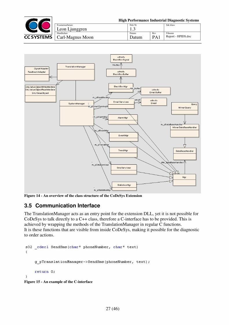
3.5 Communication Interface
The TranslationManager acts as an entry point for the extension DLL, yet it is not possible for CoDeSys to talk directly to a C++ class, therefore a C-interface has to be provided. This is achieved by wrapping the methods of the TranslationManager in regular C functions. It is these functions that are visible from inside CoDeSys, making it possible for the diagnostic to order actions.
Figure 15 - An example of the C-interface
28 (46)
Examensarbetare
Leon Ljunggren Dok Nr
1.3 Säk klass
Handledare Carl-Magnus Moon
Datum
Datum Rev
PA1 Filnamn Report - HPIDS.doc
High Performance Industrial Diagnostic Systems
sssssssSySystems
4 CODRE – CODESYS DIAGNOSTIC RUNTIME ENGINE
In order to be able to test the viability of the new system design a prototype was built and named CODRE (CoDeSys Diagnostic Runtime Engine). The prototype implements all key features of the system so that an apple-to-apple comparison between the new and the old system can be done.
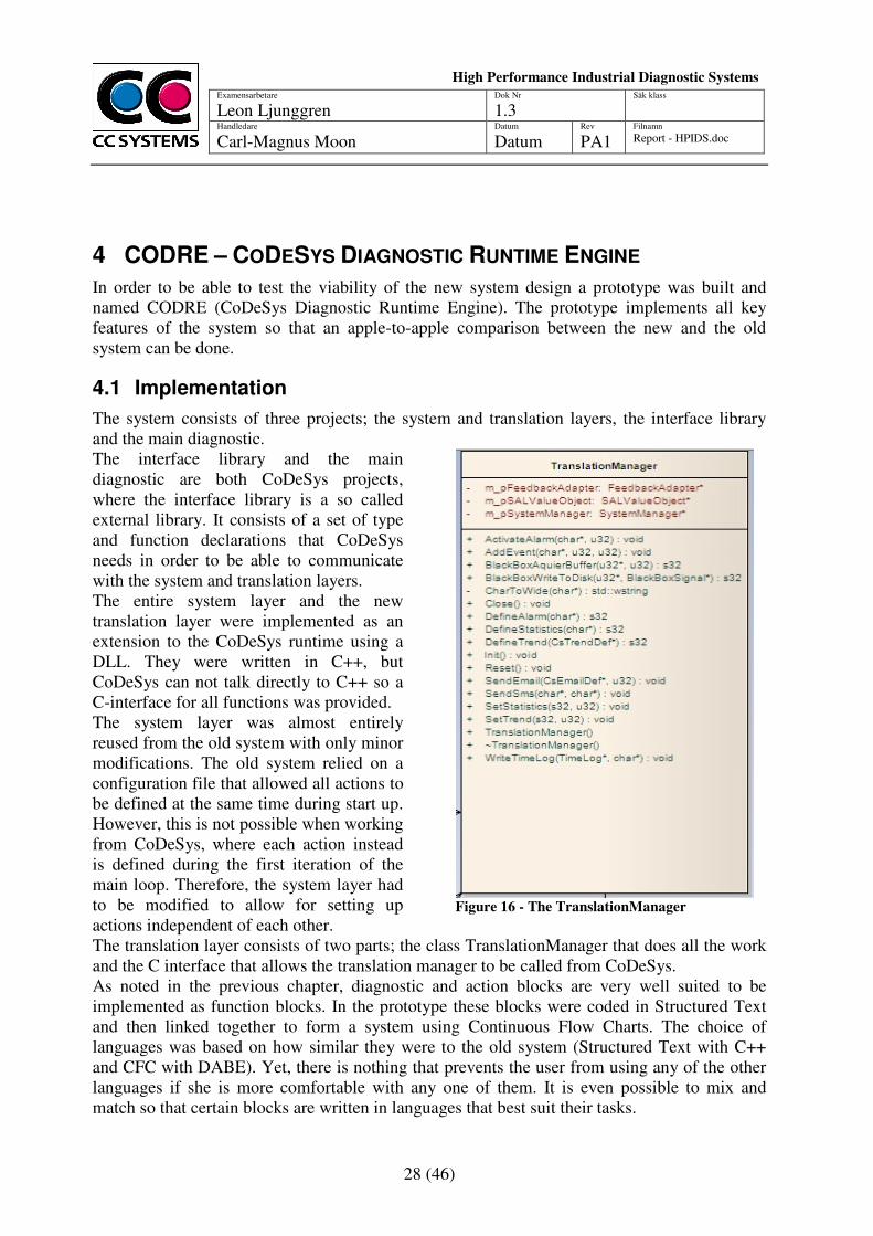
4.1 Implementation
The system consists of three projects; the system and translation layers, the interface library and the main diagnostic. The interface library and the main diagnostic are both CoDeSys projects, where the interface library is a so called external library. It consists of a set of type and function declarations that CoDeSys needs in order to be able to communicate with the system and translation layers. The entire system layer and the new translation layer were implemented as an extension to the CoDeSys runtime using a DLL. They were written in C++, but CoDeSys can not talk directly to C++ so a C-interface for all functions was provided. The system layer was almost entirely reused from the old system with only minor modifications. The old system relied on a configuration file that allowed all actions to be defined at the same time during start up. However, this is not possible when working from CoDeSys, where each action instead is defined during the first iteration of the main loop. Therefore, the system layer had to be modified to allow for setting up actions independent of each other.
Figure 16 - The TranslationManager
The translation layer consists of two parts; the class TranslationManager that does all the work and the C interface that allows the translation manager to be called from CoDeSys. As noted in the previous chapter, diagnostic and action blocks are very well suited to be implemented as function blocks. In the prototype these blocks were coded in Structured Text and then linked together to form a system using Continuous Flow Charts. The choice of languages was based on how similar they were to the old system (Structured Text with C++ and CFC with DABE). Yet, there is nothing that prevents the user from using any of the other languages if she is more comfortable with any one of them. It is even possible to mix and match so that certain blocks are written in languages that best suit their tasks.
29 (46)
Examensarbetare
Leon Ljunggren Dok Nr
1.3 Säk klass
Handledare Carl-Magnus Moon
Datum
Datum Rev
PA1 Filnamn Report - HPIDS.doc
High Performance Industrial Diagnostic Systems
sssssssSySystems
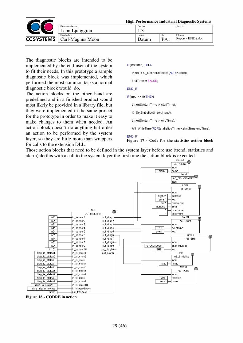
The diagnostic blocks are intended to be implemented by the end user of the system to fit their needs. In this prototype a sample diagnostic block was implemented, which performed the most common tasks a normal diagnostic block would do. The action blocks on the other hand are predefined and in a finished product would most likely be provided in a library file, but they were implemented in the same project for the prototype in order to make it easy to make changes to them when needed. An action block doesn’t do anything but order an action to be performed by the system layer, so they are little more than wrappers for calls to the extension DLL.
Figure 17 - Code for the statistics action block
Those action blocks that need to be defined in the system layer before use (trend, statistics and alarm) do this with a call to the system layer the first time the action block is executed.
Figure 18 - CODRE in action
30 (46)
Examensarbetare
Leon Ljunggren Dok Nr
1.3 Säk klass
Handledare Carl-Magnus Moon
Datum
Datum Rev
PA1 Filnamn Report - HPIDS.doc
High Performance Industrial Diagnostic Systems
sssssssSySystems
4.2 Features
The prototype is almost feature-complete compared to the old system. It implements all the possible actions (Alarm, BlackBoxWrite, E-mail, Event, SMS, Statistics, Trend and WriteBack) and a functional black box. It supports running diagnostics with multiple priority levels in multiple threads, which makes it possible to run less important diagnostics less often, thus taking up less computing power. It is even possible to run the most critical diagnostic in the same thread as the control system, ensuring that it will run without being interrupted. While the prototype supports this, it is not used due to the need of making a fair comparison with the old system during the performance tests. The database structure is exactly the same as for the old system (due to the re-use of the system layer) which also means that the GUI designed for the old system works as well. Using the system should be fairly easy for a person used to working in CoDeSys: the system can be completely setup and configured using only graphical programming. Unlike DABE, where the entire system has to be configured in one long page, CODRE supports dividing the system into smaller and more logical parts (POUs). This makes it easier to get a good overview of the system and thus it is easier to maintain.
4.3 Limitations
While the prototype implements most of the features from the old system there are a few that are missing. Most important of these is error handling. The old system will handle an error and provide logs so that the error can easily be tracked. CODRE lacks this functionality and will usually crash with cryptic error messages if something goes wrong. Good error handling would take too much time to implement in a prototype and is not needed in order to be able to compare performance (where all factors are well known, leaving little room for odd errors). Besides the error handling the black box functionality is limited. It is only possible to log one type of signal (unsigned 32 bit integers), however, this is all that is needed for the performance tests. Extending it to handle more types would be straight forward but time consuming. Since part of the system is written in C++ and runs in a DLL file it is only possible to use the system on target machines that runs some version of Windows (Windows CE or Windows XP, theoretically Windows Vista but this have not been tested) without making modifications to the code. If the system had been entirely coded in CoDeSys it would have been possible to use it on any target machine that CoDeSys supports.
4.4 Discussion and Conclusions
The prototype is easy to use and understand while at the same time quite powerful. It has the features it needs in order to be compared to the old system (support for all different actions, black box functionality, graphical configuration) while also implementing some new features (different diagnostic priority levels, ability to divide a system into smaller and more manageable parts). It also manages to reach the goal of tighter integration with the control system and it is now possible to view it as one system rather than two separate. The prototype is, however, still a prototype; it lacks some functionality (for example logging different signals types with the black box and error handling) but more importantly it has not gone through the testing and verification needed of an operational system.

31 (46)
Examensarbetare
Leon Ljunggren Dok Nr
1.3 Säk klass
Handledare Carl-Magnus Moon
Datum
Datum Rev
PA1 Filnamn Report - HPIDS.doc
High Performance Industrial Diagnostic Systems
sssssssSySystems
32 (46)
Examensarbetare
Leon Ljunggren Dok Nr
1.3 Säk klass
Handledare Carl-Magnus Moon
Datum
Datum Rev
PA1 Filnamn Report - HPIDS.doc
High Performance Industrial Diagnostic Systems
sssssssSySystems
5 PERFORMANCE
While the new system design appears to be faster on paper, due to elimination of the need to copy all signals from CoDeSys into the diagnostic system every cycle, it is not guaranteed that this speed increase is realised at runtime. It is possible that other factors can diminish the gain from not needing to copy signals, for example it could be that running code written in CoDeSys is slower than running code written in C++. In order to get conclusive proof that the new system really is faster it has to be compared to the old system in scenarios that are as close as possible to real operating conditions. The most important aspect to look at is the cycle time; the system has to be able to perform all its diagnostic every ten milliseconds. It is this limit that decides how many signals the system can handle. The new system is capable of running some of its less important diagnostics with a longer time limit. Though, in order to be able to do a fair comparison this feature will not be used during the testing. Other interesting aspects are execution time of the various components, such as the diagnostic blocks and various action blocks.
5.1 Test Implementation
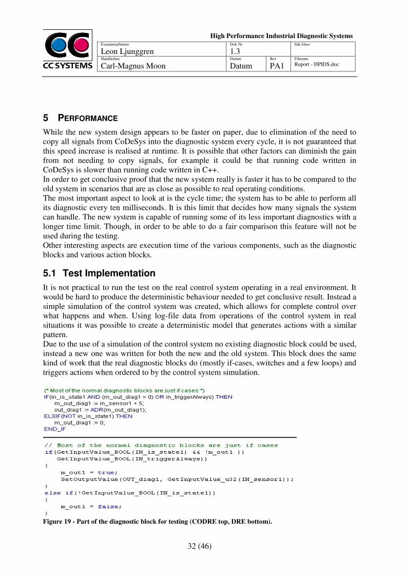
It is not practical to run the test on the real control system operating in a real environment. It would be hard to produce the deterministic behaviour needed to get conclusive result. Instead a simple simulation of the control system was created, which allows for complete control over what happens and when. Using log-file data from operations of the control system in real situations it was possible to create a deterministic model that generates actions with a similar pattern. Due to the use of a simulation of the control system no existing diagnostic block could be used, instead a new one was written for both the new and the old system. This block does the same kind of work that the real diagnostic blocks do (mostly if-cases, switches and a few loops) and triggers actions when ordered to by the control system simulation.
Figure 19 - Part of the diagnostic block for testing (CODRE top, DRE bottom).
33 (46)
Examensarbetare
Leon Ljunggren Dok Nr
1.3 Säk klass
Handledare Carl-Magnus Moon
Datum
Datum Rev
PA1 Filnamn Report - HPIDS.doc
High Performance Industrial Diagnostic Systems
sssssssSySystems
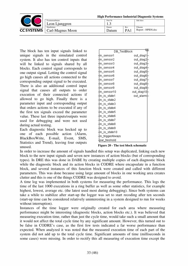
The block has ten input signals linked to unique signals in the simulated control system. It also has ten control inputs that will be linked to signals shared by all blocks. Each control signal corresponds to one output signal. Letting the control signal go high causes all actions connected to the corresponding output signal to be executed. There is also an additional control input signal that causes all outputs to order execution of their connected actions if allowed to go high. Finally there is a parameter input and corresponding output that orders actions to be executed if any of the first ten signals exceed the parameter value. These last three inputs/outputs were used for debugging and were not used during actual testing. Each diagnostic block was hocked up to one of each possible action (Alarm, BlackBoxWrite, E-mail, Event, SMS, Statistics and Trend), leaving four outputs unused.
Figure 20 - The test block schematic
In order to increase the amount of signals handled this setup was duplicated, linking each new block to the new input signals and seven new instances of action blocks (but of corresponding types). In DRE this was done in DABE by creating multiple copies of each diagnostic block while the diagnostic block and its action blocks in CODRE where encapsulate in a function block, and several instances of this function block were created and called with different parameters. This was done because using large amount of blocks in one working area creates clutter and this is one of the things CODRE was designed to avoid. A time log was implemented in both systems for measuring the performance. This logs the time of the last 1000 executions in a ring buffer as well as some other statistics, for example highest, lowest, average etc. (the latest used most during debugging). Since both systems can take a while to stabilize after start-up the logger was set to start recoding after ten seconds (start-up time can be considered relatively uninteresting in a system designed to run for weeks without interruption). Instances of the time logger were originally created for each area where measuring performance might be interesting (diagnostic blocks, action blocks etc.). It was believed that measuring execution time, rather than just the cycle time, would take such a small amount that it would not affect the total cycle time by any significant amount. However, this turned out to be false in CODRE’s case, as the first few tests indicated a far worse performance than expected. When analyzed it was noted that the measured execution time of each part of the system did not add up to the total cycle time. Significant amounts of time (milliseconds in some cases) were missing. In order to rectify this all measuring of execution time except the
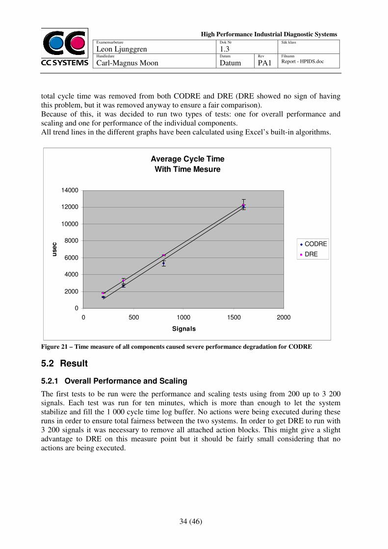
34 (46)
Examensarbetare
Leon Ljunggren Dok Nr
1.3 Säk klass
Handledare Carl-Magnus Moon
Datum
Datum Rev
PA1 Filnamn Report - HPIDS.doc
High Performance Industrial Diagnostic Systems
sssssssSySystems
total cycle time was removed from both CODRE and DRE (DRE showed no sign of having this problem, but it was removed anyway to ensure a fair comparison). Because of this, it was decided to run two types of tests: one for overall performance and scaling and one for performance of the individual components. All trend lines in the different graphs have been calculated using Excel’s built-in algorithms.
Average Cycle Time
With Time Mesure
0
2000
4000
6000
8000
10000
12000
14000
0 500 1000 1500 2000
Signals
usec CODRE
DRE
Figure 21 – Time measure of all components caused severe performance degradation for CODRE
5.2 Result
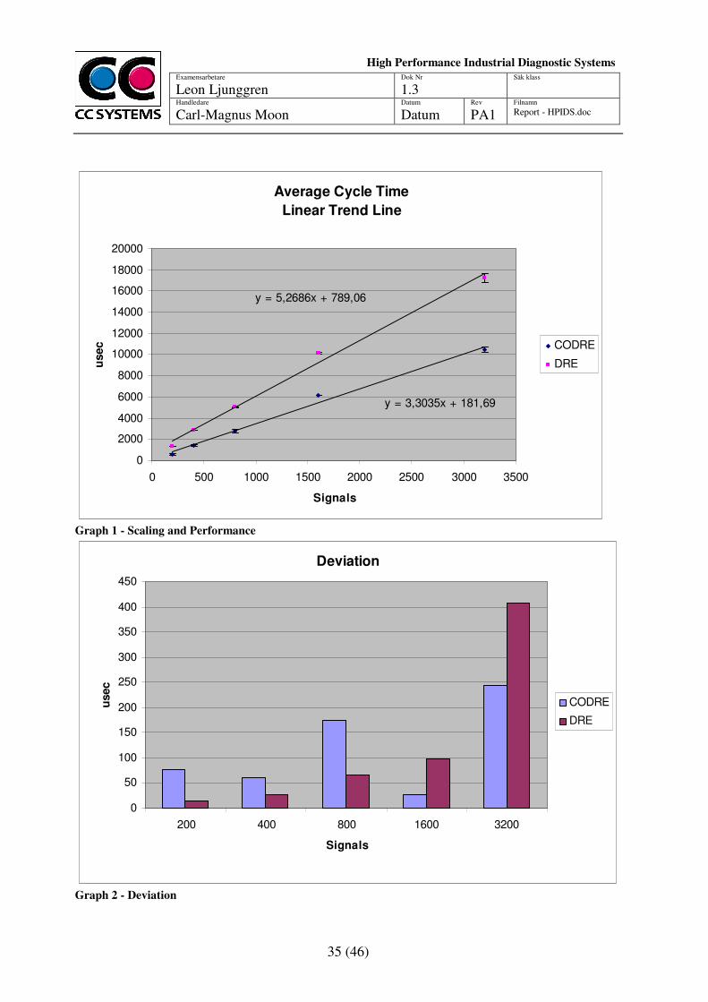
5.2.1 Overall Performance and Scaling
The first tests to be run were the performance and scaling tests using from 200 up to 3 200 signals. Each test was run for ten minutes, which is more than enough to let the system stabilize and fill the 1 000 cycle time log buffer. No actions were being executed during these runs in order to ensure total fairness between the two systems. In order to get DRE to run with 3 200 signals it was necessary to remove all attached action blocks. This might give a slight advantage to DRE on this measure point but it should be fairly small considering that no actions are being executed.
35 (46)
Examensarbetare
Leon Ljunggren Dok Nr
1.3 Säk klass
Handledare Carl-Magnus Moon
Datum
Datum Rev
PA1 Filnamn Report - HPIDS.doc
High Performance Industrial Diagnostic Systems
sssssssSySystems
Average Cycle Time
Linear Trend Line
y = 3,3035x + 181,69
y = 5,2686x + 789,06
0
2000
4000
6000
8000
10000
12000
14000
16000
18000
20000
0 500 1000 1500 2000 2500 3000 3500
Signals
usec CODRE
DRE
Graph 1 - Scaling and Performance
Deviation
0
50
100
150
200
250
300
350
400
450
200 400 800 1600 3200
Signals
usec
CODRE
DRE
Graph 2 - Deviation
36 (46)
Examensarbetare
Leon Ljunggren Dok Nr
1.3 Säk klass
Handledare Carl-Magnus Moon
Datum
Datum Rev
PA1 Filnamn Report - HPIDS.doc
High Performance Industrial Diagnostic Systems
sssssssSySystems
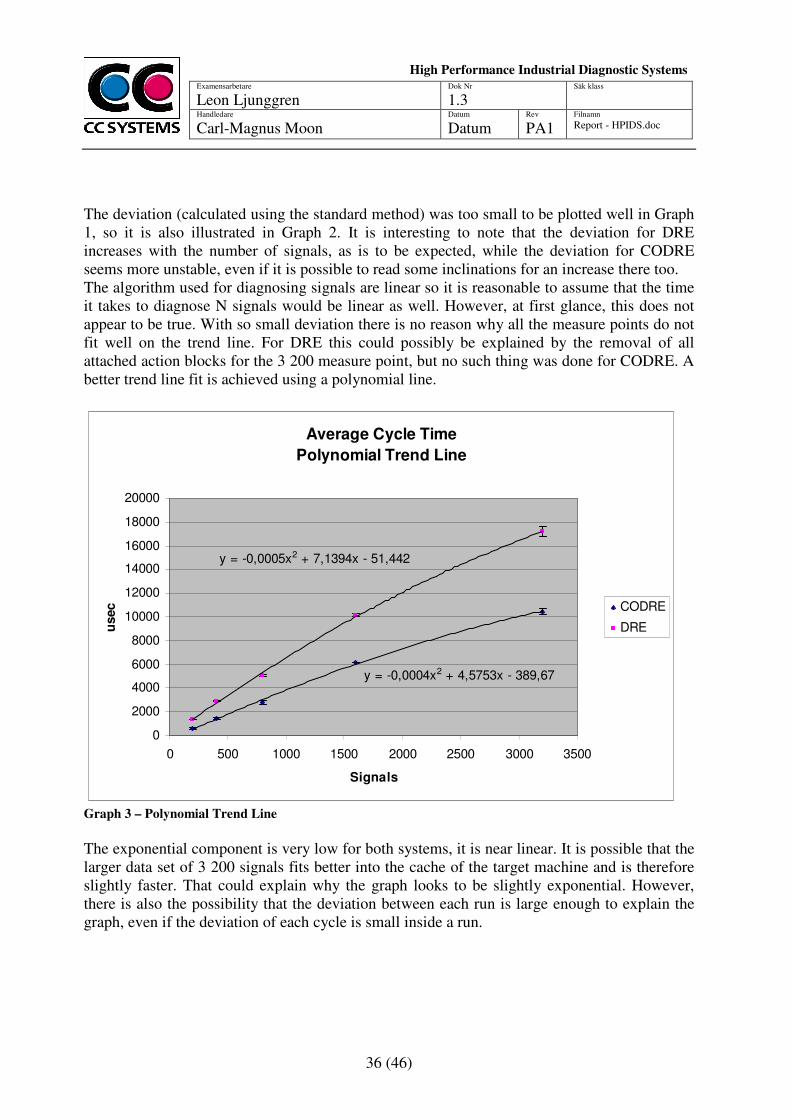
The deviation (calculated using the standard method) was too small to be plotted well in Graph 1, so it is also illustrated in Graph 2. It is interesting to note that the deviation for DRE increases with the number of signals, as is to be expected, while the deviation for CODRE seems more unstable, even if it is possible to read some inclinations for an increase there too. The algorithm used for diagnosing signals are linear so it is reasonable to assume that the time it takes to diagnose N signals would be linear as well. However, at first glance, this does not appear to be true. With so small deviation there is no reason why all the measure points do not fit well on the trend line. For DRE this could possibly be explained by the removal of all attached action blocks for the 3 200 measure point, but no such thing was done for CODRE. A better trend line fit is achieved using a polynomial line.
Average Cycle Time
Polynomial Trend Line
y = -0,0004x2 + 4,5753x - 389,67
y = -0,0005x2 + 7,1394x - 51,442
0
2000
4000
6000
8000
10000
12000
14000
16000
18000
20000
0 500 1000 1500 2000 2500 3000 3500
Signals
usec CODRE
DRE
Graph 3 – Polynomial Trend Line
The exponential component is very low for both systems, it is near linear. It is possible that the larger data set of 3 200 signals fits better into the cache of the target machine and is therefore slightly faster. That could explain why the graph looks to be slightly exponential. However, there is also the possibility that the deviation between each run is large enough to explain the graph, even if the deviation of each cycle is small inside a run.
37 (46)
Examensarbetare
Leon Ljunggren Dok Nr
1.3 Säk klass
Handledare Carl-Magnus Moon
Datum
Datum Rev
PA1 Filnamn Report - HPIDS.doc
High Performance Industrial Diagnostic Systems
sssssssSySystems
Copy Time
0
2000
4000
6000
8000
10000
12000
14000
16000
18000
20000
0 500 1000 1500 2000 2500 3000 3500
Signals
usec
CODRE
DRE
CODRE+Copy
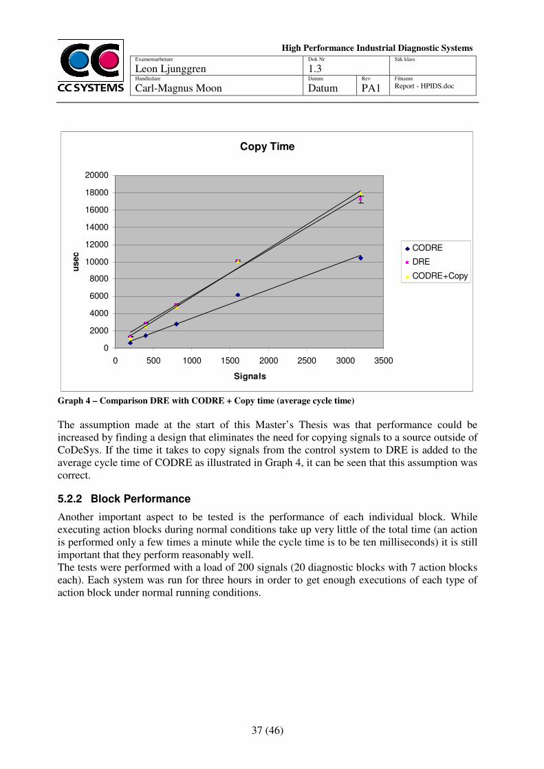
Graph 4 – Comparison DRE with CODRE + Copy time (average cycle time)
The assumption made at the start of this Master’s Thesis was that performance could be increased by finding a design that eliminates the need for copying signals to a source outside of CoDeSys. If the time it takes to copy signals from the control system to DRE is added to the average cycle time of CODRE as illustrated in Graph 4, it can be seen that this assumption was correct.
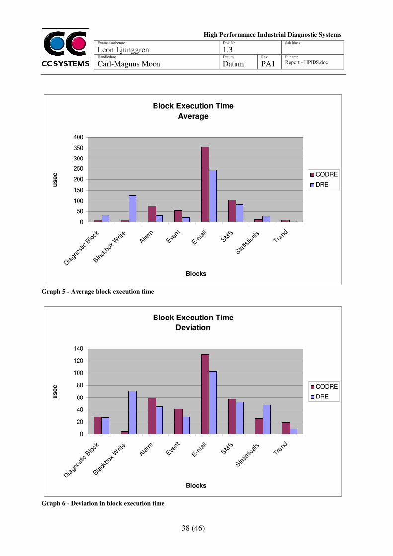
5.2.2 Block Performance
Another important aspect to be tested is the performance of each individual block. While executing action blocks during normal conditions take up very little of the total time (an action is performed only a few times a minute while the cycle time is to be ten milliseconds) it is still important that they perform reasonably well. The tests were performed with a load of 200 signals (20 diagnostic blocks with 7 action blocks each). Each system was run for three hours in order to get enough executions of each type of action block under normal running conditions.
38 (46)
Examensarbetare
Leon Ljunggren Dok Nr
1.3 Säk klass
Handledare Carl-Magnus Moon
Datum
Datum Rev
PA1 Filnamn Report - HPIDS.doc
High Performance Industrial Diagnostic Systems
sssssssSySystems
Block Execution Time
Average
0
50
100
150
200
250
300
350
400
Dia
gnos
tic B
lock
Black
box W
rite
Alarm
Eve
nt
E-m
ail
SM
S
Sta
tistic
als
Trend
Blocks
usec CODRE
DRE
Graph 5 - Average block execution time
Block Execution Time
Deviation
0
20
40
60
80
100
120
140
Dia
gnos
tic B
lock
Black
box W
rite
Alarm
Eve
nt
E-m
ail
SM
S
Sta
tistic
als
Trend
Blocks
usec CODRE
DRE
Graph 6 - Deviation in block execution time
39 (46)
Examensarbetare
Leon Ljunggren Dok Nr
1.3 Säk klass
Handledare Carl-Magnus Moon
Datum
Datum Rev
PA1 Filnamn Report - HPIDS.doc
High Performance Industrial Diagnostic Systems
sssssssSySystems
As can be seen in Graph 5, the performance of CODRE’s action blocks is generally a bit worse than that of DRE. However, it is on the scale of microseconds. This is most likely due to the action blocks being called from a DLL rather than a normal function like in DRE. It is very interesting to note that the CODRE diagnostic block, which is completely implemented in CoDeSys, is actually faster than the DRE diagnostic block. This is most likely due to differences in implementation rather than CoDeSys code being faster than C++. For example, in the CODRE diagnostic block the signals can be accessed as a normal variable while in DRE’s case they need to be requested from the signal adaptation layer. Having to request the signal from the signal adaptation layer is also most likely the reason why statistics is slower in DRE since that is not needed for CODRE. Similarly CODRE’s black box write action is faster due to implementation differences; the DRE black box write action will store the black box to RAM and then order it stored to the hard drive while CODRE’s will just order it stored to the hard drive.
5.3 Discussion and Conclusion
The testing shows that CODRE is capable of dealing with almost twice as many signals as DRE while still maintaining the required ten millisecond cycle time. It is slightly slower at ordering the most common actions, however, the extra time is measured in microseconds, which means that it is insignificant considering that actions are only ordered a few times a minute at most. As is illustrated in Graph 4 the difference between the two systems is the time it takes to copy all signals from the control system into DRE. If that time is removed from the equation then they perform almost exactly the same. This proves that the assumption made at the beginning of the project was correct; a large performance gain was to be found by eliminating signal copying to a source outside of CoDeSys. It is also interesting because it indicates that CoDeSys code is able to execute just as fast as C++ code. It would be interesting to do further testing in order to determine exactly why both system seemed to indicate none-linear scaling. However access to the hardware (the CC Pilot XS computer) is limited, preventing further testing. The fact that DRE refused to even start with a load of 3 200 signals without removing all attached action blocks puts a real limit to how far that system can go, even if future hardware would make it possible to run that many signals under the required ten millisecond cycle time. CODRE, on the other hand, could continue scaling to even more signals if provided with faster hardware.
40 (46)
Examensarbetare
Leon Ljunggren Dok Nr
1.3 Säk klass
Handledare Carl-Magnus Moon
Datum
Datum Rev
PA1 Filnamn Report - HPIDS.doc
High Performance Industrial Diagnostic Systems
sssssssSySystems
6 DISCUSSION
This Master’s Thesis started with the assumption that eliminating the need to copy signals from the control system in CoDeSys to the diagnostic system would greatly improve performance and scalability. The test results seem to validate this assumption, yet there were many other goals which were not as easy to measure. For example it required that the system should be easy to setup and configure, and that is not something that can be easily measured. In this case that goal was of a secondary nature, since it was not as important as proving that there was performance to be gained from the new design, so no usability tests were performed with real end users. This is of course a weakness, however, there was neither time, nor resources for such studies. The system is intended for other software engineers and is thus designed to allow them to adapt it to suit their needs. Unlike the old system where a configuration editor (DABE) had to be used, the new system allows engineers to work with any of the six languages provided by CoDeSys and to do as they wish with the components provided. This means more freedom to do what is needed but that does not necessarily translate into easier to use. Still, since the engineer is allowed to work with something she is familiar with (CoDeSys), it should still have the same effect in this case. The test results seem conclusive but it is important to remember that they were done using a simulated control system. While the simulation did its best to model the real system’s behaviour, it can not get all aspects exactly right. In order to get absolutely conclusive results the tests should be run in a real operating environment, and even then it is possible that the measure system could somewhat skew the results like it did initially. Although such testing might produce some changes in the initial results it is not likely to change the end result, namely that CODRE is significantly faster than DRE.

41 (46)
Examensarbetare
Leon Ljunggren Dok Nr
1.3 Säk klass
Handledare Carl-Magnus Moon
Datum
Datum Rev
PA1 Filnamn Report - HPIDS.doc
High Performance Industrial Diagnostic Systems
sssssssSySystems
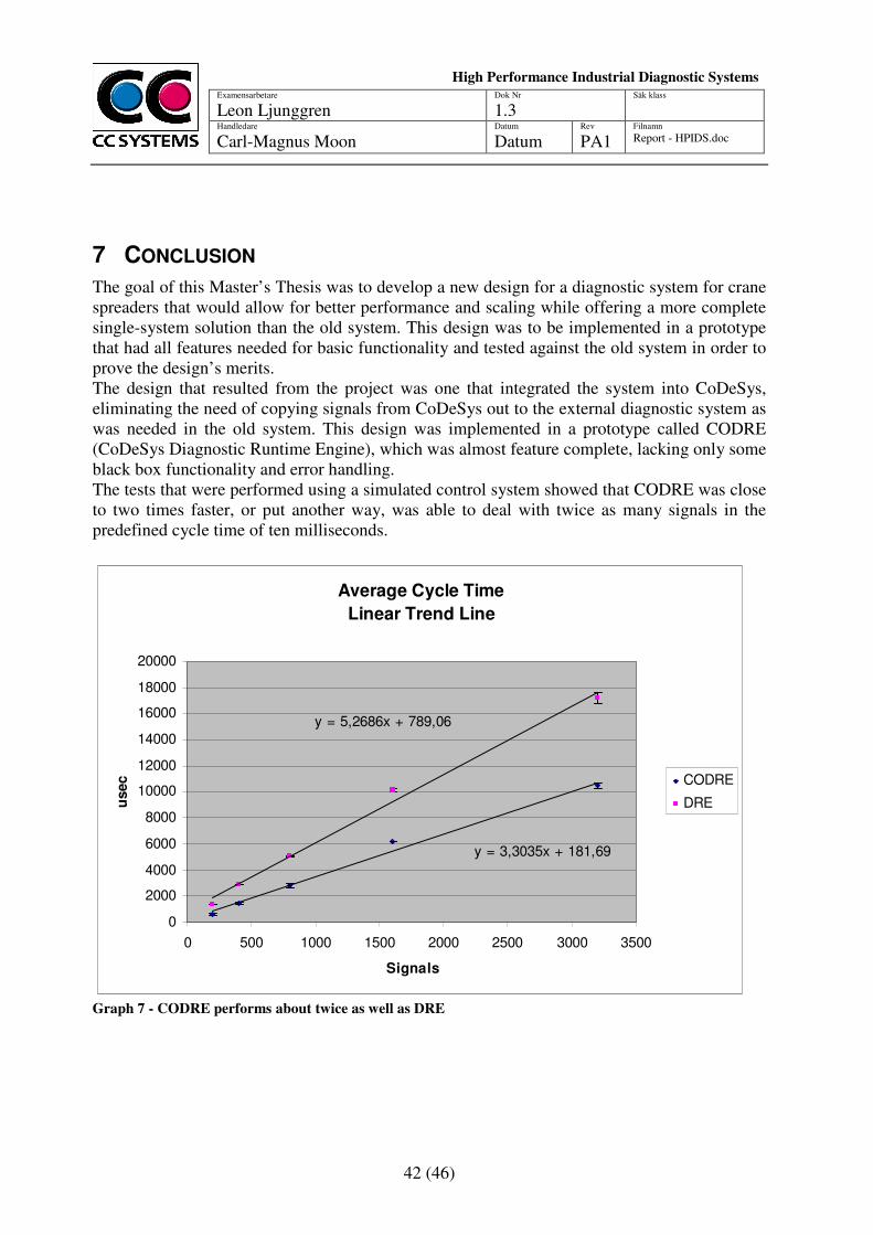
42 (46)
Examensarbetare
Leon Ljunggren Dok Nr
1.3 Säk klass
Handledare Carl-Magnus Moon
Datum
Datum Rev
PA1 Filnamn Report - HPIDS.doc
High Performance Industrial Diagnostic Systems
sssssssSySystems
7 CONCLUSION
The goal of this Master’s Thesis was to develop a new design for a diagnostic system for crane spreaders that would allow for better performance and scaling while offering a more complete single-system solution than the old system. This design was to be implemented in a prototype that had all features needed for basic functionality and tested against the old system in order to prove the design’s merits. The design that resulted from the project was one that integrated the system into CoDeSys, eliminating the need of copying signals from CoDeSys out to the external diagnostic system as was needed in the old system. This design was implemented in a prototype called CODRE (CoDeSys Diagnostic Runtime Engine), which was almost feature complete, lacking only some black box functionality and error handling. The tests that were performed using a simulated control system showed that CODRE was close to two times faster, or put another way, was able to deal with twice as many signals in the predefined cycle time of ten milliseconds.
Average Cycle Time
Linear Trend Line
y = 3,3035x + 181,69
y = 5,2686x + 789,06
0
2000
4000
6000
8000
10000
12000
14000
16000
18000
20000
0 500 1000 1500 2000 2500 3000 3500
Signals
usec CODRE
DRE
Graph 7 - CODRE performs about twice as well as DRE

43 (46)
Examensarbetare
Leon Ljunggren Dok Nr
1.3 Säk klass
Handledare Carl-Magnus Moon
Datum
Datum Rev
PA1 Filnamn Report - HPIDS.doc
High Performance Industrial Diagnostic Systems
sssssssSySystems
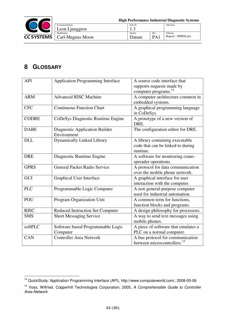
44 (46)
Examensarbetare
Leon Ljunggren Dok Nr
1.3 Säk klass
Handledare Carl-Magnus Moon
Datum
Datum Rev
PA1 Filnamn Report - HPIDS.doc
High Performance Industrial Diagnostic Systems
sssssssSySystems
8 GLOSSARY
API Application Programming Interface A source code interface that
supports requests made by computer programs.14
ARM Advanced RISC Machine A computer architecture common in embedded systems.
CFC Continuous Function Chart A graphical programming language in CoDeSys.
CODRE CoDeSys Diagnostic Runtime Engine A prototype of a new version of DRE.
DABE Diagnostic Application Builder Environment
The configuration editor for DRE.
DLL Dynamically Linked Library A library containing executable code that can be linked to during runtime.
DRE Diagnostic Runtime Engine A software for monitoring crane-spreader operations.
GPRS General Packet Radio Service A protocol for data communication over the mobile phone network.
GUI Graphical User Interface A graphical interface for user interaction with the computer.
PLC Programmable Logic Computer A non general-purpose computer used for industrial automation.
POU Program Organization Unit A common term for functions, function blocks and programs.
RISC Reduced Instruction Set Computer A design philosophy for processors. SMS Short Messaging Service A way to send text messages using
mobile phones. softPLC Software based Programmable Logic
Computer A piece of software that emulates a PLC on a normal computer.
CAN Controller Area Network A bus protocol for communication between microcontrollers.15
14
QuickStudy: Application Programming Interface (API), http://www.computerworld.com/, 2008-05-06
15 Voss, Wilfried, Copperhill Technologies Corporation, 2005, A Comprehensible Guide to Controller
Area Network

45 (46)
Examensarbetare
Leon Ljunggren Dok Nr
1.3 Säk klass
Handledare Carl-Magnus Moon
Datum
Datum Rev
PA1 Filnamn Report - HPIDS.doc
High Performance Industrial Diagnostic Systems
sssssssSySystems
46 (46)
Examensarbetare
Leon Ljunggren Dok Nr
1.3 Säk klass
Handledare Carl-Magnus Moon
Datum
Datum Rev
PA1 Filnamn Report - HPIDS.doc
High Performance Industrial Diagnostic Systems
sssssssSySystems
9 REFERENCES
[1] CC-Systems About Us, 2008-04-17, http://www.cc-systems.com [2] 3S – Smart Software Solutions, 2007, User Manual for PLC Programming with CoDeSys
2.3
[3] Liu, Layland, Association for Computing Machinery, 1973, Scheduling Algorithms for
Multiprogramming in a Hard-Real-Time Environment [4] Tiegelkamp, John, Springer, 2001, IEC 61131-3: programming Industrial Automation
Systems [5] Brainerd, W.S., Landweber, L.H., John Wiley & Sons Inc, 1974, Theory of Computation. [6] Blume, Peter A., Prentice Hall, 2007, The LabVIEW Style Book [7] 3S – Smart Software Solutions, 2008, CoDeSys SP 32 Bit Full Multitasking Runtime
System for 32-Bit Processors
[8][10] Intel XScale® Technology http://www.intel.com/design/intelxscale/, 2008-05-06 [9] Welcome to Windows CE 5.0, http://msdn.microsoft.com/en-us/library/ms905511.aspx, 2008-05-06 [11] http://en.wikipedia.org/wiki/X86, 2008-05-06 [12] SiSoftware Sandra 2008 Benchmark. [13] Interview with Matthias Maier, employee at 3S – Smart Software Solutions [14] QuickStudy: Application Programming Interface (API) http://www.computerworld.com/, 2008-05-06 [15] Voss, Wilfried, Copperhill Technologies Corporation, 2005, A Comprehensible Guide to
Controller Area Network


![High Pressure Diagnostic UK v2[1].3](https://img.pdfslide.tips/doc/110x75/55cf9a20550346d033a090c4/high-pressure-diagnostic-uk-v213.jpg)