Embed Size (px)
Citation preview

NIPPON STEEL TECHNICAL REPORT No. 96 July 2007
- 50 -
UDC 669 . 14 - 426 . 2 : 621 . 785 . 47
High-Performance Wire Rods Produced with DLPHiroshi OHBA*1 Seiki NISHIDA*2
Toshimi TARUI*3 Koji YOSHIMURA*1
Masaichi SUGIMOTO*4 Kazumi MATSUOKA*5
Naoshi HIKITA*1 Masahiro TODA*3
Abstract
DLP (Direct in-Line Patenting) wire rods multiplied equal to or more than 20
years from the entry into production and the dosage expanded steady by them. The
product basic concept of the DLP wire rods is the energy saving wire rods which can
omit the lead patenting processing which is implemented by the customer. Also, one
reason why DLP wire rods are increasingly used is that the heat-treatment is in line
with efforts to protect our global environment because lead is not applied. This paper
introduces the basic characteristics of the DLP wire rods and high-strengthened
DLP wire rods which were commercialized recently in the market.
1. IntroductionDLP (direct in-line patenting) wire rod products have been used
since the start of their production in 1985 as products that satisfy theneeds of the age, contributing to energy saving and protection of theenvironment. The main selling point of the DLP wire rods in theearly days of their production was the omission of lead patentingthat had been used in wire rod user fabrication processes. In fact, thecharacteristic merit of the wire rods has successfully helped toconserve energy at users. In a later phase of the market situation,moreover, they favorably met the new concept of global environmentimprovement to increase the number of wire rod users year afteryear who use DLP wire rods do not contain lead. Recently, studiesare being conducted on fluidized bed patenting with the use of high-speed jet gas cooling to completely supersede lead patenting whichis conventionally used as intermediate patenting1).
The DLP wire rod is one of the main in-line heat-treated productsof Nippon Steel and is the only product that has maintained its productposition constantly for over 20 years since the start of production,supported by metallurgical operation know-how, hot molten salttreating equipment, and equipment maintenance technology/know-how. This report describes the basic performance of the DLP wirerod and some examples of its recent applications to high-strength
uses to meet market demands in the form of galvanized steel wiresfor high-strength PC strands and high-strength bridges.
2. DLP Wires and Rods2.1 General description of DLP wires and rods
Fig. 1 is an outline of the DLP equipment to directly heat-treatsteel wire rods by patenting, using a molten salt as a refrigerant. Theequipment comprises a separate cooling bath and a thermostatic bath.The cooling bath can be set to any temperature suited for specificwire rod to be treated, with an initial cooling rate taken into account.The thermostatic bath causes to produce fine pearlite by treating thework at a pearlite transformation nose temperature to assure an
*1 Kimitsu Works*2 Kimitsu R&D Lab.*3 Steel Research Laboratories
*4 Steel Structure R&D Center (Presently Structural Div.)*5 Steel Structure R&D Center
Fig. 1 Outline of the DLP equipment
NIPPON STEEL TECHNICAL REPORT No. 96 July 2007
- 51 -
efficient transformation at a constant temperature.2.2 Microstructure of DLP wire rod
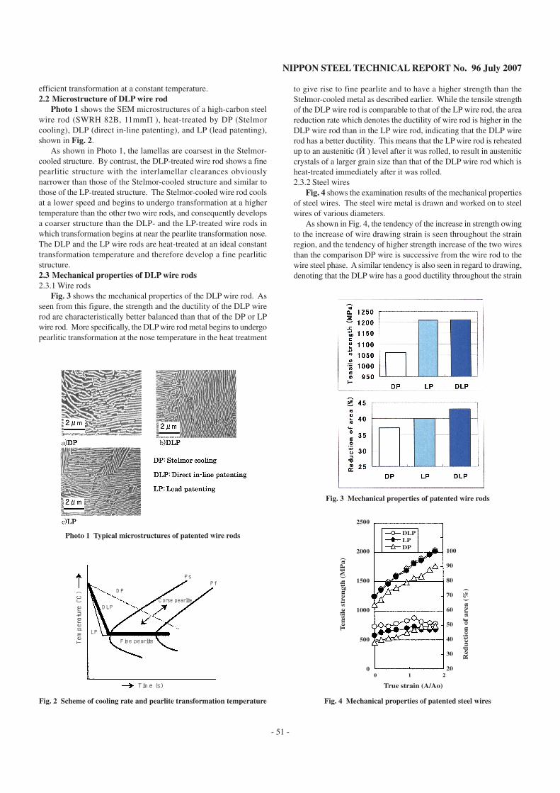
Photo 1 shows the SEM microstructures of a high-carbon steelwire rod (SWRH 82B, 11mmφ), heat-treated by DP (Stelmorcooling), DLP (direct in-line patenting), and LP (lead patenting),shown in Fig. 2.
As shown in Photo 1, the lamellas are coarsest in the Stelmor-cooled structure. By contrast, the DLP-treated wire rod shows a finepearlitic structure with the interlamellar clearances obviouslynarrower than those of the Stelmor-cooled structure and similar tothose of the LP-treated structure. The Stelmor-cooled wire rod coolsat a lower speed and begins to undergo transformation at a highertemperature than the other two wire rods, and consequently developsa coarser structure than the DLP- and the LP-treated wire rods inwhich transformation begins at near the pearlite transformation nose.The DLP and the LP wire rods are heat-treated at an ideal constanttransformation temperature and therefore develop a fine pearliticstructure.2.3 Mechanical properties of DLP wire rods2.3.1 Wire rods
Fig. 3 shows the mechanical properties of the DLP wire rod. Asseen from this figure, the strength and the ductility of the DLP wirerod are characteristically better balanced than that of the DP or LPwire rod. More specifically, the DLP wire rod metal begins to undergopearlitic transformation at the nose temperature in the heat treatment
to give rise to fine pearlite and to have a higher strength than theStelmor-cooled metal as described earlier. While the tensile strengthof the DLP wire rod is comparable to that of the LP wire rod, the areareduction rate which denotes the ductility of wire rod is higher in theDLP wire rod than in the LP wire rod, indicating that the DLP wirerod has a better ductility. This means that the LP wire rod is reheatedup to an austenitic (γ) level after it was rolled, to result in austeniticcrystals of a larger grain size than that of the DLP wire rod which isheat-treated immediately after it was rolled.2.3.2 Steel wires
Fig. 4 shows the examination results of the mechanical propertiesof steel wires. The steel wire metal is drawn and worked on to steelwires of various diameters.
As shown in Fig. 4, the tendency of the increase in strength owingto the increase of wire drawing strain is seen throughout the strainregion, and the tendency of higher strength increase of the two wiresthan the comparison DP wire is successive from the wire rod to thewire steel phase. A similar tendency is also seen in regard to drawing,denoting that the DLP wire has a good ductility throughout the strain
PfPs
DP
DLP
LP
Fine pearlite
Corse pearlite
Temperature (
˚C)
Time (s)
Fig. 2 Scheme of cooling rate and pearlite transformation temperature
Photo 1 Typical microstructures of patented wire rods
True strain (A/Ao)
Red
uct
ion
of
area
(%
)
Ten
sile
str
engt
h (
MP
a)
2500
2000
1500
1000
500
0
100
90
80
70
60
50
40
30
20 0 1 2
DLPLPDP
Fig. 3 Mechanical properties of patented wire rods
Fig. 4 Mechanical properties of patented steel wires
NIPPON STEEL TECHNICAL REPORT No. 96 July 2007
- 52 -
region. The ductility of the DLP wire rod confirmed in the wire roddrawing stage as superior to that of the LP wire rod is inherited bythe DLP steel wire to give it a higher ductility to the LP steel wire.2.4 Methods for increasing strength of high-carbon steel wires
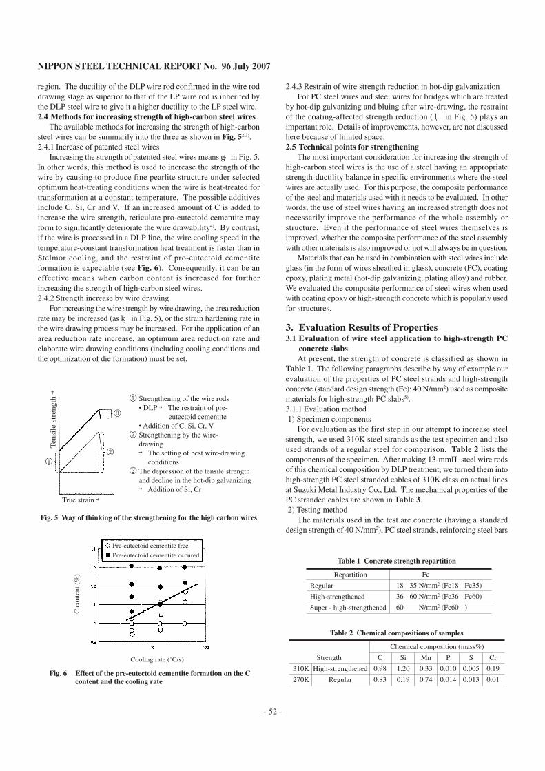
The available methods for increasing the strength of high-carbonsteel wires can be summarily into the three as shown in Fig. 52,3).2.4.1 Increase of patented steel wires
Increasing the strength of patented steel wires means ① in Fig. 5.In other words, this method is used to increase the strength of thewire by causing to produce fine pearlite structure under selectedoptimum heat-treating conditions when the wire is heat-treated fortransformation at a constant temperature. The possible additivesinclude C, Si, Cr and V. If an increased amount of C is added toincrease the wire strength, reticulate pro-eutectoid cementite mayform to significantly deteriorate the wire drawability4). By contrast,if the wire is processed in a DLP line, the wire cooling speed in thetemperature-constant transformation heat treatment is faster than inStelmor cooling, and the restraint of pro-eutectoid cementiteformation is expectable (see Fig. 6). Consequently, it can be aneffective means when carbon content is increased for furtherincreasing the strength of high-carbon steel wires.2.4.2 Strength increase by wire drawing
For increasing the wire strength by wire drawing, the area reductionrate may be increased (as ② in Fig. 5), or the strain hardening rate inthe wire drawing process may be increased. For the application of anarea reduction rate increase, an optimum area reduction rate andelaborate wire drawing conditions (including cooling conditions andthe optimization of die formation) must be set.
2.4.3 Restrain of wire strength reduction in hot-dip galvanizationFor PC steel wires and steel wires for bridges which are treated
by hot-dip galvanizing and bluing after wire-drawing, the restraintof the coating-affected strength reduction (③ in Fig. 5) plays animportant role. Details of improvements, however, are not discussedhere because of limited space.2.5 Technical points for strengthening
The most important consideration for increasing the strength ofhigh-carbon steel wires is the use of a steel having an appropriatestrength-ductility balance in specific environments where the steelwires are actually used. For this purpose, the composite performanceof the steel and materials used with it needs to be evaluated. In otherwords, the use of steel wires having an increased strength does notnecessarily improve the performance of the whole assembly orstructure. Even if the performance of steel wires themselves isimproved, whether the composite performance of the steel assemblywith other materials is also improved or not will always be in question.
Materials that can be used in combination with steel wires includeglass (in the form of wires sheathed in glass), concrete (PC), coatingepoxy, plating metal (hot-dip galvanizing, plating alloy) and rubber.We evaluated the composite performance of steel wires when usedwith coating epoxy or high-strength concrete which is popularly usedfor structures.
3. Evaluation Results of Properties3.1 Evaluation of wire steel application to high-strength PC
concrete slabsAt present, the strength of concrete is classified as shown in
Table 1. The following paragraphs describe by way of example ourevaluation of the properties of PC steel strands and high-strengthconcrete (standard design strength (Fc): 40 N/mm2) used as compositematerials for high-strength PC slabs5).3.1.1 Evaluation method 1) Specimen components
For evaluation as the first step in our attempt to increase steelstrength, we used 310K steel strands as the test specimen and alsoused strands of a regular steel for comparison. Table 2 lists thecomponents of the specimen. After making 13-mmφ steel wire rodsof this chemical composition by DLP treatment, we turned them intohigh-strength PC steel stranded cables of 310K class on actual linesat Suzuki Metal Industry Co., Ltd. The mechanical properties of thePC stranded cables are shown in Table 3. 2) Testing method
The materials used in the test are concrete (having a standarddesign strength of 40 N/mm2), PC steel strands, reinforcing steel bars
③
①②
① Strengthening of the wire rods • DLP → The restraint of pre- eutectoid cementite • Addition of C, Si, Cr, V② Strengthening by the wire- drawing → The setting of best wire-drawing conditions③ The depression of the tensile strength and decline in the hot-dip galvanizing → Addition of Si, Cr
True strain →
Ten
sile
str
engt
h →
Fig. 5 Way of thinking of the strengthening for the high carbon wires
Table 1 Concrete strength repartition
Repartition
Regular
High-strengthened
Super - high-strengthened
Fc
18 - 35 N/mm2 (Fc18 - Fc35)
36 - 60 N/mm2 (Fc36 - Fc60)
60 - N/mm2 (Fc60 - )
Table 2 Chemical compositions of samples
Strength
310K
270K
High-strengthened
Regular
C
0.98
0.83
Si
1.20
0.19
Mn
0.33
0.74
P
0.010
0.014
S
0.005
0.013
Cr
0.19
0.01
Chemical composition (mass%)
Pre-eutectoid cementite free
Pre-eutectoid cementite occured
Cooling rate (˚C/s)
C c
onte
nt (
%)
Fig. 6 Effect of the pre-eutectoid cementite formation on the Ccontent and the cooling rate
NIPPON STEEL TECHNICAL REPORT No. 96 July 2007
- 53 -
(arranged in the direction of the slab top and bottom supports and inthe direction perpendicular to the supports), and PC steel anchoringparts.
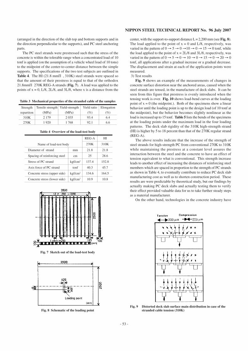
The PC steel strands were prestressed such that the stress of theconcrete is within the tolerable range when a concentrated load of 10tonf is applied (on the assumption of a vehicle wheel load of 10 tons)to the midpoint of the center-to-center distance between the simplesupports. The specifications of the two test subjects are outlined inTable 4. The HI (21.8 mmφ , 310K) steel strands were spaced sothat the amount of their prestress is equal to that of the orthodox21.8mmφ 270K REG-A strands (Fig. 7). A load was applied to thepoints of x = 0, L/8, 2L/8, and 3L/8, where x is a distance from the
center, with the support-to-support distance L = 2,200 mm (see Fig. 8).The load applied to the point of x = 0 and L/8, respectively, wasvaried in the pattern of 0 → 5 → 0 →10 → 0 → 15 → 0 tonf, whilethe load applied to the point of x = 2L/8 and 3L/8, respectively, wasvaried in the pattern of 0 → 5 → 0 → 10 → 0 → 15 → 0 → 20 → 0tonf, all applications after a gradual increase or a gradual decrease.The displacement and strain at each of the application points weremeasured. 3) Test results
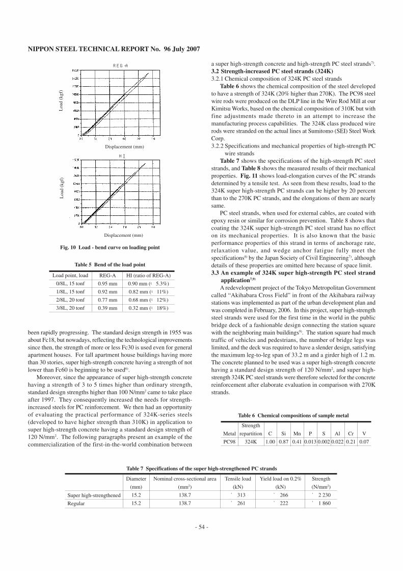
Fig. 9 shows an example of the measurements of changes inconcrete surface distortion near the anchored areas, caused when thesteel strands are tensed, in the manufacture of deck slabs. It can beseen from this figure that prestress is evenly introduced when thetensing work is over. Fig. 10 shows load-bend curves at the loadingpoint of x = 0 (the midpoint.). Both of the specimens show a linearbehavior until the loading point is up to the design load (of 10 tonf atthe midpoint), but the behavior becomes slightly nonlinear as theload is increased up to 15 tonf. Table 5 lists the bends of the specimensat the loading points under the maximum load in the four loadingpatterns. The deck slab rigidity of the 310K high-strength strand(HI) is higher by 5 to 18 percent than that of the 270K regular strand(REG-A).
The above results indicate that the increase of the strength ofsteel strands for high-strength PC from conventional 270K to 310Kwhile maintaining the prestress at a constant level assures theinteraction between the steel and the concrete to have an effect oftension equivalent to what is conventional. This strength increaseleads to another effect of increasing the distances of reinforcing steelmembers which are spaced in proportion to the strength of PC strandsas shown in Table 4, to eventually contribute to reduce PC deck slabmanufacturing cost as well as to shorten construction period. Theseresults are were predictable by theoretical study, but our findings byactually making PC deck slabs and actually testing them to verifytheir effect provided valuable data for us to take further steady stepsas a material manufacturer.
On the other hand, technologies in the concrete industry have
Table 3 Mechanical properties of the stranded cable of the samples
Strength
repartiton
310K
270K
Tensile strength
(MPa)
2 179
1 920
Yield-strength
(MPa)
2 035
1 768
Yield ratio
(%)
93.4
92.1
Elongation
(%)
6.4
6.6
Table 4 Overview of the load-test body
Diameter of strand
Spacing of reinforcing steel
Stress of PC strand
Axis force of PC strand
Concrete stress (upper side)
Concrete stress (lower side)
mm
cm
kgf/cm2
tonf
kgf/cm2
kgf/cm2
REG-A
270K
21.8
25
137.4
40.3
134.6
10.9
HI
310K
21.8
28.6
152.8
45.7
164.5
10.8
Name of load-test body
Fig. 7 Sketch out of the load-test body
Fig. 8 Schematic of the loading pointFig. 9 Distorted deck slab surface main distribution in case of the
stranded cable tension (310K)
NIPPON STEEL TECHNICAL REPORT No. 96 July 2007
- 54 -
been rapidly progressing. The standard design strength in 1955 wasabout Fc18, but nowadays, reflecting the technological improvementssince then, the strength of more or less Fc30 is used even for generalapartment houses. For tall apartment house buildings having morethan 30 stories, super high-strength concrete having a strength of notlower than Fc60 is beginning to be used6).
Moreover, since the appearance of super high-strength concretehaving a strength of 3 to 5 times higher than ordinary strength,standard design strengths higher than 100 N/mm2 came to take placeafter 1997. They consequently increased the needs for strength-increased steels for PC reinforcement. We then had an opportunityof evaluating the practical performance of 324K-series steels(developed to have higher strength than 310K) in application tosuper high-strength concrete having a standard design strength of120 N/mm2. The following paragraphs present an example of thecommercialization of the first-in-the-world combination between
a super high-strength concrete and high-strength PC steel strands7).3.2 Strength-increased PC steel strands (324K)3.2.1 Chemical composition of 324K PC steel strands
Table 6 shows the chemical composition of the steel developedto have a strength of 324K (20% higher than 270K). The PC98 steelwire rods were produced on the DLP line in the Wire Rod Mill at ourKimitsu Works, based on the chemical composition of 310K but withfine adjustments made thereto in an attempt to increase themanufacturing process capabilities. The 324K class produced wirerods were stranded on the actual lines at Sumitomo (SEI) Steel WorkCorp.3.2.2 Specifications and mechanical properties of high-strength PC
wire strandsTable 7 shows the specifications of the high-strength PC steel
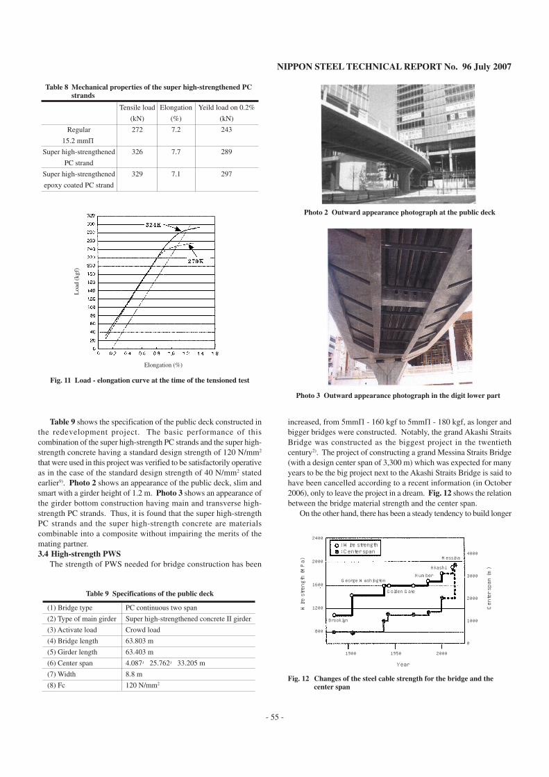
strands, and Table 8 shows the measured results of their mechanicalproperties. Fig. 11 shows load-elongation curves of the PC strandsdetermined by a tensile test. As seen from these results, load to the324K super high-strength PC strands can be higher by 20 percentthan to the 270K PC strands, and the elongations of them are nearlysame.
PC steel strands, when used for external cables, are coated withepoxy resin or similar for corrosion prevention. Table 8 shows thatcoating the 324K super high-strength PC steel strand has no effecton its mechanical properties. It is also known that the basicperformance properties of this strand in terms of anchorage rate,relaxation value, and wedge anchor fatigue fully meet thespecifications8) by the Japan Society of Civil Engineering7), althoughdetails of these properties are omitted here because of space limit.3.3 An example of 324K super high-strength PC steel strand
application7,9)
A redevelopment project of the Tokyo Metropolitan Governmentcalled “Akihabara Cross Field” in front of the Akihabara railwaystations was implemented as part of the urban development plan andwas completed in February, 2006. In this project, super high-strengthsteel strands were used for the first time in the world in the publicbridge deck of a fashionable design connecting the station squarewith the neighboring main buildings9). The station square had muchtraffic of vehicles and pedestrians, the number of bridge legs waslimited, and the deck was required to have a slender design, satisfyingthe maximum leg-to-leg span of 33.2 m and a girder high of 1.2 m.The concrete planned to be used was a super high-strength concretehaving a standard design strength of 120 N/mm2, and super high-strength 324K PC steel strands were therefore selected for the concretereinforcement after elaborate evaluation in comparison with 270Kstrands.
Displacement (mm)
Displacement (mm)
REG-A
HI
Loa
d (k
gf)
Loa
d (k
gf)
Fig. 10 Load - bend curve on loading point
Table 5 Bend of the load point
Load point, load
0/8L, 15 tonf
1/8L, 15 tonf
2/8L, 20 tonf
3/8L, 20 tonf
REG-A
0.95 mm
0.92 mm
0.77 mm
0.39 mm
HI (ratio of REG-A)
0.90 mm (-5.3%)
0.82 mm (-11%)
0.68 mm (-12%)
0.32 mm (-18%)
Table 7 Specifications of the super high-strengthened PC strands
Super high-strengthened
Regular
Diameter
(mm)
15.2
15.2
Nominal cross-sectional area
(mm2)
138.7
138.7
Tensile load
(kN)
≧ 313
≧ 261
Yield load on 0.2%
(kN)
≧ 266
≧ 222
Strength
(N/mm2)
≧ 2 230
≧ 1 860
Table 6 Chemical compositions of sample metal
Metal
PC98
Strength
repartition
324K
C
1.00
Si
0.87
Mn
0.41
P
0.013
S
0.002
Al
0.022
Cr
0.21
V
0.07
NIPPON STEEL TECHNICAL REPORT No. 96 July 2007
- 55 -
Fig. 11 Load - elongation curve at the time of the tensioned test
Table 8 Mechanical properties of the super high-strengthened PCstrands
Regular
15.2 mmφSuper high-strengthened
PC strand
Super high-strengthened
epoxy coated PC strand
Tensile load
(kN)
272
326
329
Elongation
(%)
7.2
7.7
7.1
Yeild load on 0.2%
(kN)
243
289
297
Elongation (%)
Loa
d (k
gf)
Table 9 shows the specification of the public deck constructed inthe redevelopment project. The basic performance of thiscombination of the super high-strength PC strands and the super high-strength concrete having a standard design strength of 120 N/mm2
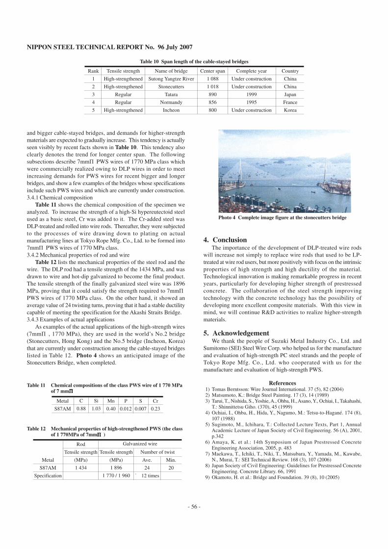
that were used in this project was verified to be satisfactorily operativeas in the case of the standard design strength of 40 N/mm2 statedearlier9). Photo 2 shows an appearance of the public deck, slim andsmart with a girder height of 1.2 m. Photo 3 shows an appearance ofthe girder bottom construction having main and transverse high-strength PC strands. Thus, it is found that the super high-strengthPC strands and the super high-strength concrete are materialscombinable into a composite without impairing the merits of themating partner.3.4 High-strength PWS
The strength of PWS needed for bridge construction has been
increased, from 5mmφ- 160 kgf to 5mmφ- 180 kgf, as longer andbigger bridges were constructed. Notably, the grand Akashi StraitsBridge was constructed as the biggest project in the twentiethcentury2). The project of constructing a grand Messina Straits Bridge(with a design center span of 3,300 m) which was expected for manyyears to be the big project next to the Akashi Straits Bridge is said tohave been cancelled according to a recent information (in October2006), only to leave the project in a dream. Fig. 12 shows the relationbetween the bridge material strength and the center span.
On the other hand, there has been a steady tendency to build longer
Table 9 Specifications of the public deck
(1) Bridge type
(2) Type of main girder
(3) Activate load
(4) Bridge length
(5) Girder length
(6) Center span
(7) Width
(8) Fc
PC continuous two span
Super high-strengthened concrete II girder
Crowd load
63.803 m
63.403 m
4.087+25.762+33.205 m
8.8 m
120 N/mm2
Photo 3 Outward appearance photograph in the digit lower part
Photo 2 Outward appearance photograph at the public deck
: Wire strength: Center span
Messina
Akashi
George WashingtonHumber
Golden Gate
Brooklyn
2400
2000
1600
1200
800
4000
3000
2000
1000
0
1900 1950 2000
Year
Wire strength (MPa)
Center span (m)
Fig. 12 Changes of the steel cable strength for the bridge and thecenter span
NIPPON STEEL TECHNICAL REPORT No. 96 July 2007
- 56 -
Table 10 Span length of the cable-stayed bridges
Rank
1
2
3
4
5
Tensile strength
High-strengthened
High-strengthened
Regular
Regular
High-strengthened
Name of bridge
Sutong Yangtze River
Stonecutters
Tatara
Normandy
Incheon
Center span
1 088
1 018
890
856
800
Complete year
Under construction
Under construction
1999
1995
Under construction
Country
China
China
Japan
France
Korea
and bigger cable-stayed bridges, and demands for higher-strengthmaterials are expected to gradually increase. This tendency is actuallyseen visibly by recent facts shown in Table 10. This tendency alsoclearly denotes the trend for longer center span. The followingsubsections describe 7mmφ PWS wires of 1770 MPa class whichwere commercially realized owing to DLP wires in order to meetincreasing demands for PWS wires for recent bigger and longerbridges, and show a few examples of the bridges whose specificationsinclude such PWS wires and which are currently under construction.3.4.1 Chemical composition
Table 11 shows the chemical composition of the specimen weanalyzed. To increase the strength of a high-Si hypereutectoid steelused as a basic steel, Cr was added to it. The Cr-added steel wasDLP-treated and rolled into wire rods. Thereafter, they were subjectedto the processes of wire drawing down to plating on actualmanufacturing lines at Tokyo Rope Mfg. Co., Ltd. to be formed into7mmφ PWS wires of 1770 MPa class.3.4.2 Mechanical properties of rod and wire
Table 12 lists the mechanical properties of the steel rod and thewire. The DLP rod had a tensile strength of the 1434 MPa, and wasdrawn to wire and hot-dip galvanized to become the final product.The tensile strength of the finally galvanized steel wire was 1896MPa, proving that it could satisfy the strength required to 7mmφPWS wires of 1770 MPa class. On the other hand, it showed anaverage value of 24 twisting turns, proving that it had a stable ductilitycapable of meeting the specification for the Akashi Straits Bridge.3.4.3 Examples of actual applications
As examples of the actual applications of the high-strength wires(7mmφ , 1770 MPa), they are used in the world’s No.2 bridge(Stonecutters, Hong Kong) and the No.5 bridge (Incheon, Korea)that are currently under construction among the cable-stayed bridgeslisted in Table 12. Photo 4 shows an anticipated image of theStonecutters Bridge, when completed.
4. ConclusionThe importance of the development of DLP-treated wire rods
will increase not simply to replace wire rods that used to be LP-treated at wire rod users, but more positively with focus on the intrinsicproperties of high strength and high ductility of the material.Technological innovation is making remarkable progress in recentyears, particularly for developing higher strength of prestressedconcrete. The collaboration of the steel strength improvingtechnology with the concrete technology has the possibility ofdeveloping more excellent composite materials. With this view inmind, we will continue R&D activities to realize higher-strengthmaterials.
5. AcknowledgementWe thank the people of Suzuki Metal Industry Co., Ltd. and
Sumitomo (SEI) Steel Wire Corp. who helped us for the manufactureand evaluation of high-strength PC steel strands and the people ofTokyo Rope Mfg. Co., Ltd. who cooperated with us for themanufacture and evaluation of high-strength PWS.
References1) Tomas Berntsson: Wire Journal International. 37 (5), 82 (2004)2) Matsumoto, K.: Bridge Steel Painting. 17 (3), 14 (1989)3) Tarui, T., Nishida, S., Yoshie, A., Ohba, H., Asano, Y., Ochiai, I., Takahashi,
T.: Shinnittetsu Giho. (370), 45 (1999)4) Ochiai, I., Ohba, H., Hida, Y., Nagumo, M.: Tetsu-to-Hagané. 174 (8),
107 (1988)5) Sugimoto, M., Ichihara, T.: Collected Lecture Texts, Part 1, Annual
Academic Lecture of Japan Society of Civil Engineering. 56 (A), 2001,p.342
6) Amaya, K. et al.: 14th Symposium of Japan Prestressed ConcreteEngineering Association, 2005, p. 483
7) Maekawa, T., Ichiki, T., Niki, T., Matsubara, Y., Yamada, M., Kawabe,N., Murai, T.: SEI Technical Review. 168 (3), 107 (2006)
8) Japan Society of Civil Engineering: Guidelines for Prestressed ConcreteEngineering. Concrete Library. 66, 1991
9) Okamoto, H. et al.: Bridge and Foundation. 39 (8), 10 (2005)
Table 11 Chemical compositions of the class PWS wire of 1 770 MPaof 7 mmφφφφφ
Metal
S87AM
C
0.88
Si
1.03
Mn
0.40
P
0.012
S
0.007
Cr
0.23
Table 12 Mechanical properties of high-strengthened PWS (the classof 1 770MPa of 7mmφφφφφ )
Metal
S87AM
Specification
Rod
Tensile strength
(MPa)
1 434
Tensile strength
(MPa)
1 896
1 770 / 1 960
Ave.
24
≧ 12 times
Min.
20
Number of twist
Galvanized wire
Photo 4 Complete image figure at the stonecutters bridge