Embed Size (px)
Citation preview

EN
IR3455
HIGH VOLTAGE INSULATION TESTER
Instruction Manual
Oct. 2016 Edition 1IR3455A961-00 16-10H


1
2
3
4
5
6
7
8
9
10
11
付録
索引
i
Contents
Introduction ......................................................1Verifying Package Contents / Open the case ..1Safety Information ...........................................5Operating Precautions ..................................... 9
1 Overview 19
1.1 Product Overview ................................. 191.2 Features ...............................................211.3 Measurement Overview .......................231.4 Names and Functions of Parts .............291.5 Screen Setup .......................................33
2 Measurement Preparations 35
2.1 Supplying Power .................................. 352.1.1 Installing or Replacing the Battery...... 362.1.2 Installing the Battery Pack (Rechargeable
nickel-hydrogen battery) ..................... 392.1.3 Connecting the AC Adapter................ 452.1.4 Charging the Battery Pack ................. 47
2.2 Turning Power On and Off ...................502.2.1 Auto Power Off ................................... 51
2.3 Setting and Checking Date and Time ..522.3.1 Setting Date and Time........................ 522.3.2 Checking Date and Time.................... 55
2.4 Connecting Test Lead ..........................562.5 Connecting Temperature Sensor .........58
IR3455A961-00
ii
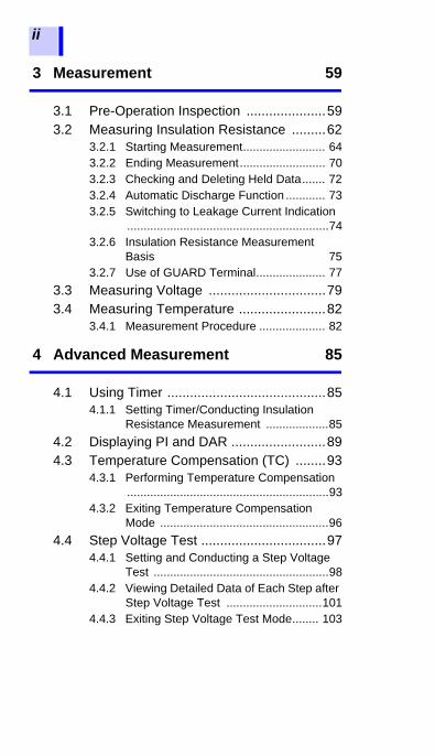
3 Measurement 59
3.1 Pre-Operation Inspection .....................593.2 Measuring Insulation Resistance .........62
3.2.1 Starting Measurement......................... 643.2.2 Ending Measurement.......................... 703.2.3 Checking and Deleting Held Data....... 723.2.4 Automatic Discharge Function ............ 733.2.5 Switching to Leakage Current Indication
.............................................................743.2.6 Insulation Resistance Measurement
Basis 753.2.7 Use of GUARD Terminal..................... 77
3.3 Measuring Voltage ...............................793.4 Measuring Temperature .......................82
3.4.1 Measurement Procedure .................... 82
4 Advanced Measurement 85
4.1 Using Timer ..........................................854.1.1 Setting Timer/Conducting Insulation
Resistance Measurement ...................854.2 Displaying PI and DAR .........................894.3 Temperature Compensation (TC) ........93
4.3.1 Performing Temperature Compensation.............................................................93
4.3.2 Exiting Temperature Compensation Mode ...................................................96
4.4 Step Voltage Test .................................974.4.1 Setting and Conducting a Step Voltage
Test .....................................................984.4.2 Viewing Detailed Data of Each Step after
Step Voltage Test .............................1014.4.3 Exiting Step Voltage Test Mode........ 103

1
2
3
4
5
6
7
8
9
10
11
付録
索引
iii
5 Recording Measurement Data
(Memory Function) 1055.1 Recording Measurement Data ...........1075.1.1 Manual Recording (Recording result of
one measurement session) 1075.1.2 Logging Recording (Recording at regular
intervals) ........................................... 1105.2 Checking Recorded Data ................... 1185.3 Deleting Recorded Data .....................123
5.3.1 Deleting Data of Chosen No............. 1235.3.2 Deleting all Data ............................... 124
6 Other Functions 125
6.1 Changing and Checking Interval Setting for PI Calculation ................................ 1256.1.1 Changing Interval Setting ................. 1256.1.2 Checking Interval Setting ................. 127
6.2 Changing and Checking Voltage Application Time for Step Voltage Test ............................................................1286.2.1 Changing Time Setting..................... 1286.2.2 Checking Time Setting ..................... 130
6.3 Entering Temperature and Humidity Measured with External Thermometer and Hygrometer ........................................1316.3.1 Entering and Saving ......................... 1326.3.2 Clearing Indications of Temperature and
Humidity Stored Data ....................... 1356.4 Communicating with PC .....................136
6.4.1 Installing Data Analysis Software for 3455 ............................................. 137
6.4.2 Installing Driver................................. 1386.4.3 Downloading Data to Save to PC/ Setting
up Instrument on PC 139

iv
7 Specifications 141
7.1 General Specifications .......................1417.2 Measurement Specifications ..............146
7.2.1 Insulation Resistance Measurement. 1467.2.2 Leakage Current Measurement ........ 1497.2.3 Voltage Measurement....................... 1507.2.4 Temperature Measurement .............. 151
7.3 9750-01/-02/-03/-11/-12/-13 and 9751-01/-02/-03 ALLIGATOR CLIPs Specifications .....................................152
8 Maintenance and Service 153
8.1 Troubleshooting .................................1548.2 Cleaning .............................................1568.3 Error Display ......................................1568.4 Performing System Reset ..................1588.5 Discarding the Instrument ..................159
Appendix 163
Appendix 1 Test Voltage Characteristic Graph .................163
Appendix 2 Example of Insulation Resistance Criteria ......................................164
Appendix 3 Example of PI Criteria (Polarization Index) ...................164
Appendix 4 Temperature Compensation Table ..................................................165

Introduction
1
2
3
4
5
6
7
8
9
10
11
付録
索引
1
Introduction
Thank you for purchasing the Hioki IR3455High Voltage Insulation Tester. To obtainmaximum performance from the instru-ment, please read this manual first, andkeep it handy for future reference.• Microsoft and Windows are either regis-tered trademarks or trademarks ofMicrosoft Corporation in the United Statesand other countries.
• Adobe and Adobe Reader are trademarksof Adobe Systems Incorporated.
Verifying Package Contents / Open the case
When you receive the instrument, inspect itcarefully to ensure that no damageoccurred during shipping. In particular,check the accessories, panel switches, andconnectors. If damage is evident, or if it failsto operate according to the specifications,contact your authorized Hioki distributor orreseller.
Open the case by releasing the two latches.(See next page.)
Registered trade mark
Open the caseAppearance of Case
Cover
Latches
Handle

Verifying Package Contents / Open the case
2
Procedure
1. Draw the latch outwards with your fin-ger.
2. While raising the entire latch, place afinger on the top of the latch and pullit out.
Verifying Package Contents / Open the case
1
2
3
4
5
6
7
8
9
10
11
付録
索引
3
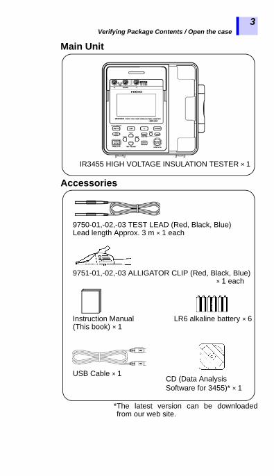
Main Unit
Accessories
*The latest version can be downloadedfrom our web site.
IR3455 HIGH VOLTAGE INSULATION TESTER × 1
9750-01,-02,-03 TEST LEAD (Red, Black, Blue)Lead length Approx. 3 m × 1 each
LR6 alkaline battery × 6Instruction Manual (This book) × 1
USB Cable × 1
9751-01,-02,-03 ALLIGATOR CLIP (Red, Black, Blue) × 1 each
CD (Data Analysis Software for 3455)* × 1
Verifying Package Contents / Open the case
4
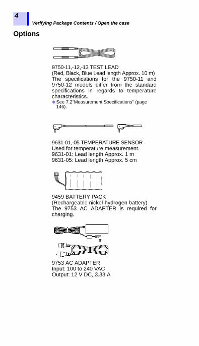
Options
9750-11,-12,-13 TEST LEAD(Red, Black, Blue Lead length Approx. 10 m)The specifications for the 9750-11 and9750-12 models differ from the standardspecifications in regards to temperaturecharacteristics.See 7.2"Measurement Specifications" (page
146).
9631-01,-05 TEMPERATURE SENSORUsed for temperature measurement.9631-01: Lead length Approx. 1 m 9631-05: Lead length Approx. 5 cm
9459 BATTERY PACK(Rechargeable nickel-hydrogen battery)The 9753 AC ADAPTER is required forcharging.
9753 AC ADAPTERInput: 100 to 240 VACOutput: 12 V DC, 3.33 A

Safety Information
1
2
3
4
5
6
7
8
9
10
11
付録
索引
5
Safety Information
This instrument is designed to conform to IEC 61010 SafetyStandards, and has been thoroughly tested for safety priorto shipment. However, using the instrument in a way notdescribed in this manual may negate the provided safetyfeatures.Before using the instrument, be certain to carefully read thefollowing safety notes:Mishandling during use could result ininjury or death, as well as damage to theinstrument. Be certain that you under-stand the instructions and precautions inthe manual before use.
• Protective gearThis instrument measures live lines. Toprevent electric shock, use appropriateprotective insulation and adhere toapplicable laws and regulations.
• With regard to the electricity supply,there are risks of electric shock, heatgeneration, fire, and arc flash due toshort circuits. Individuals using an elec-trical measuring instrument for the firsttime should be supervised by a techni-cian who has experience in electricalmeasurement.

Safety Information
6
Symbols on the instrument
Symbols for standards
Indicates cautions and hazards. When the symbol is printed on the instrument, refer to a corresponding topic in the Instruction Manual.Indicates that dangerous voltage may be present at this terminal.
Indicates a double-insulated device.
Indicates DC (Direct Current).
Indicates AC (Alternating Current).
Indicates that the product conforms to regulations set out by the EC Directive.
Indicates the Waste Electrical and Electronic Equip-ment Directive (WEEE Directive) in EU member states.
Safety Information
1
2
3
4
5
6
7
8
9
10
11
付録
索引
7
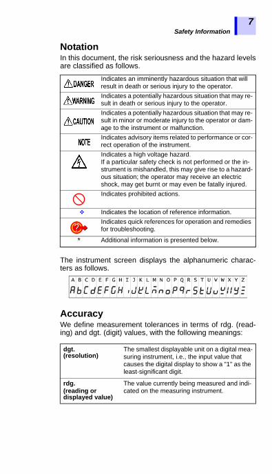
Notation
In this document, the risk seriousness and the hazard levelsare classified as follows.The instrument screen displays the alphanumeric charac-ters as follows.
AccuracyWe define measurement tolerances in terms of rdg. (read-ing) and dgt. (digit) values, with the following meanings:
Indicates an imminently hazardous situation that will result in death or serious injury to the operator.Indicates a potentially hazardous situation that may re-sult in death or serious injury to the operator.Indicates a potentially hazardous situation that may re-sult in minor or moderate injury to the operator or dam-age to the instrument or malfunction.Indicates advisory items related to performance or cor-rect operation of the instrument.Indicates a high voltage hazard.If a particular safety check is not performed or the in-strument is mishandled, this may give rise to a hazard-ous situation; the operator may receive an electric shock, may get burnt or may even be fatally injured.Indicates prohibited actions.
Indicates the location of reference information.Indicates quick references for operation and remedies for troubleshooting.
* Additional information is presented below.
dgt. (resolution)
The smallest displayable unit on a digital mea-suring instrument, i.e., the input value that causes the digital display to show a "1" as the least-significant digit.
rdg. (reading or displayed value)
The value currently being measured and indi-cated on the measuring instrument.

Safety Information
8
Measurement categories
To ensure safe operation of measuring instruments, IEC 61010 establishes safety standards for various electrical environments, categorized as CAT II to CAT IV, and called measurement categories.• Using a measuring instrument in anenvironment designated with a higher-numbered category than that for whichthe instrument is rated could result in asevere accident, and must be carefullyavoided.
• Never use a measuring instrument thatlacks category labeling in a CAT II toCAT IV measurement environment.Doing so could result in a serious acci-dent.
CAT II Primary electrical circuits in equipment con-nected to an AC electrical outlet by a powercord (portable tools, household appliances,etc.) CAT II covers directly measuring elec-trical outlet receptacles.
CAT III Primary electrical circuits of heavy equip-ment (fixed installations) connected directlyto the distribution panel, and feeders fromthe distribution panel to outlets.
CAT IV The circuit from the service drop to the ser-vice entrance, and to the power meter andprimary overcurrent protection device (dis-tribution panel).

Operating Precautions
1
2
3
4
5
6
7
8
9
10
11
付録
索引
9
Operating Precautions
Follow these precautions to ensure safe operation and toobtain the full benefits of the various functions.Before using the instrument, verify that itoperates normally to ensure that no dam-age occurred during storage or shipping. Ifyou find any damage, contact your autho-rized Hioki distributor or reseller.
During shipment of the instrument, handle itcarefully so that it is not damaged due to avibration or shock.
Preliminary Checks
If the test lead or the instrument is dam-aged, there is a risk of electric shock.Perform the following inspection beforeusing the instrument:• Before using the instrument check that
the coating of the test leads are neitherripped nor torn and that no metal partsare exposed. Using the instrumentunder such conditions could result inelectric shock. Replace the test leadswith those specified by our company.
• Verify that the instrument operates nor-mally to ensure that no damageoccurred during storage or shipping. Ifyou find any damage, contact yourauthorized Hioki distributor or reseller.
• To prevent an electric shock, confirmthat the white or red portion (insulationlayer) inside the cable is not exposed. Ifa color inside the cable is exposed, donot use the cable.
Precautions during shipment

Operating Precautions
10
Operating temperature and humidity range: P.141Temperature and humidity range for guaranteed accuracy: P.148 to P.150
Placement
Installing the instrument in inappropriatelocations may cause a malfunction ofinstrument or may give rise to an acci-dent. Avoid the following locations:• Exposed to direct sunlight or high tem-
perature• Exposed to corrosive or combustible
gases• Exposed to a strong electromagnetic
field or electrostatic charge• Near induction heating systems (such
as high-frequency induction heatingsystems and IH cooking equipment)
• Susceptible to vibration• Exposed to water, oil, chemicals, or sol-
vents• Exposed to high humidity or condensa-
tion• Exposed to high quantities of dust parti-
cles

Operating Precautions
1
2
3
4
5
6
7
8
9
10
11
付録
索引
11
Observe the following to avoid electricshock and short circuits.• Before connecting or disconnecting the
test leads to/from the instrument, besure to disconnect the test leads fromthe object under test and turn off power.
• Do not perform measurement with thebattery cover removed.
• Do not use the shut-ter if it is broken.
• To avoid electric shock, do not remove the instrument's case. The inter-nal components of the instrument carry high voltages and may become very hot during operation.
• Do not use the instrument in environ-ments containing ignitable gases, explosive powders, etc. (Risk of explo-sion)
• Do not place the instrument on an unstable table or an inclined place. Dropping or knocking down the instru-ment can cause injury or damage to the instrument.
• Do not use the instrument with circuits that exceed its ratings or specifications. Doing so may damage the instrument or cause it to become hot, resulting in bodily injury/electric shock.
• Before using the instrument, informthose around you of your intention todo so.
• To prevent instrument damage orelectric shock, use only the screw forsecuring the battery cover in place thatare originally installed. If you have losta screw or find that a screw is damaged,please contact your Hioki distributor fora replacement.
Shutter
Operating Precautions
12
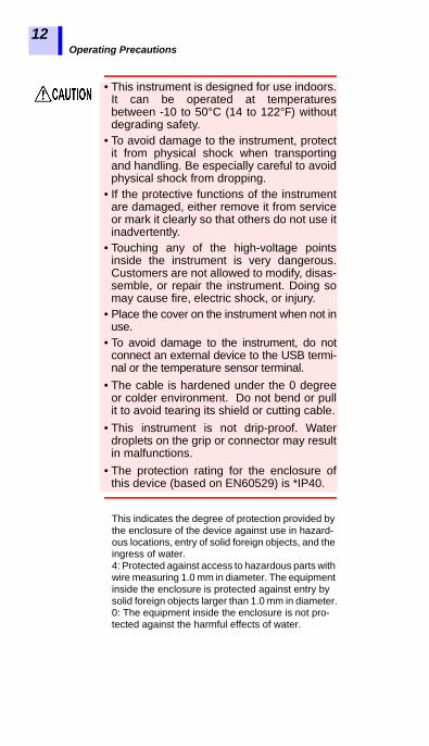
This indicates the degree of protection provided by the enclosure of the device against use in hazard-ous locations, entry of solid foreign objects, and the ingress of water.4: Protected against access to hazardous parts with wire measuring 1.0 mm in diameter. The equipment inside the enclosure is protected against entry by solid foreign objects larger than 1.0 mm in diameter.0: The equipment inside the enclosure is not pro-tected against the harmful effects of water.
• This instrument is designed for use indoors.It can be operated at temperaturesbetween -10 to 50°C (14 to 122°F) withoutdegrading safety.
• To avoid damage to the instrument, protectit from physical shock when transportingand handling. Be especially careful to avoidphysical shock from dropping.
• If the protective functions of the instrumentare damaged, either remove it from serviceor mark it clearly so that others do not use itinadvertently.
• Touching any of the high-voltage pointsinside the instrument is very dangerous.Customers are not allowed to modify, disas-semble, or repair the instrument. Doing somay cause fire, electric shock, or injury.
• Place the cover on the instrument when not inuse.
• To avoid damage to the instrument, do notconnect an external device to the USB termi-nal or the temperature sensor terminal.
• The cable is hardened under the 0 degreeor colder environment. Do not bend or pullit to avoid tearing its shield or cutting cable.
• This instrument is not drip-proof. Waterdroplets on the grip or connector may resultin malfunctions.
• The protection rating for the enclosure ofthis device (based on EN60529) is *IP40.

Operating Precautions
1
2
3
4
5
6
7
8
9
10
11
付録
索引
13
• After use, always turn off the power.• Standby State
The use of "standby state" in this manualmeans that measurement is not beingperformed and that no parameters areset. This includes the state in which
is on.• If the instrument is exposed to an abrupt
large variation in temperature,condensation may occur, resulting inmeasurement errors.Leave the instrument in a newenvironment for a while before startingmeasurement.

Operating Precautions
14
Measurement
• It is recommend to make measurementson the secondary side of distributionpanels. Measuring the primary side,where the current capacity is muchlarger, could cause damage to theinstrument or panel in the event of ashort-circuit.
• Do not short the two measurement lineswith the metal portion of the tips of thetest leads. Doing so may cause arcingor otherwise result in a seriousaccident.
• To avoid short circuit or electric shock,do not touch the metal parts of theconnecting cable clips.
• To prevent electric shock, when mea-suring the voltage of a power line useonly the specified test lead.
• The optional test leads provided withthis instrument conform to the safetystandard EN61010. Use a test lead inaccordance with its defined measure-ment category and rated voltage.
To avoid damage to the instrument, do notapply voltage or current to temperatureprobe.
Operating Precautions
1
2
3
4
5
6
7
8
9
10
11
付録
索引
15
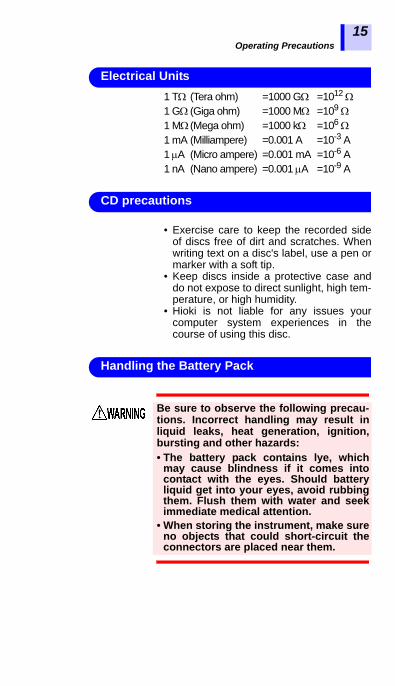
1 T (Tera ohm) =1000 G =1012 1 G (Giga ohm) =1000 M =109 1 M (Mega ohm) =1000 k =106 1 mA (Milliampere) =0.001 A =10-3 A1 A (Micro ampere) =0.001 mA =10-6 A1 nA (Nano ampere) =0.001 A =10-9 A
• Exercise care to keep the recorded sideof discs free of dirt and scratches. Whenwriting text on a disc's label, use a pen ormarker with a soft tip.
• Keep discs inside a protective case anddo not expose to direct sunlight, high tem-perature, or high humidity.
• Hioki is not liable for any issues yourcomputer system experiences in thecourse of using this disc.
Electrical Units
CD precautions
Be sure to observe the following precau-tions. Incorrect handling may result inliquid leaks, heat generation, ignition,bursting and other hazards:• The battery pack contains lye, which
may cause blindness if it comes intocontact with the eyes. Should batteryliquid get into your eyes, avoid rubbingthem. Flush them with water and seekimmediate medical attention.
• When storing the instrument, make sureno objects that could short-circuit theconnectors are placed near them.
Handling the Battery Pack

Operating Precautions
16
Observe the following to avoid damage tothe instrument:• Use the battery pack in an ambient temper-
ature range of 0 to 40°C and charge it in anambient temperature range of 0 to 40°C.
• If the battery pack fails to finish chargingwithin the stipulated time, disconnect theAC adapter to stop charging and contactyour dealer or Hioki representative.
• Consult your dealer or nearest service sta-tion should liquid leaks, strange odor, heat,discoloration, deformation and other abnor-mal conditions occur during use, chargingor storage. Should these conditions occurduring use or charging, turn off and discon-nect the instrument immediately.
• Do not expose the instrument to water anddo not use it in excessively humid locationsor locations exposed to rain.
• Do not expose the instrument to strongimpacts and do not throw it around.
Heed the following instructions to avoid bat-tery performance drop or leakage. • Do no mix old and new batteries, or differ-
ent types of batteries.• Pay attention to the polarity markings "+-",
so that you do not insert the batteries thewrong way around.
• Do not use batteries after their recom-mended expiry date.
• Do not leave a depleted batteries inside theinstrument.
• Replace batteries only with the specifiedtype.
• Remove the batteries or battery pack fromthe instrument if it is to be stored for a longtime.

Operating Precautions
1
2
3
4
5
6
7
8
9
10
11
付録
索引
17
• The battery pack is a consumable. If youare able to use the instrument for only alimited period of time despite the batterypack being properly charged, the batterypack's service life is at an end, and itshould be replaced.
• When a battery pack that has not beenused for a long time is used, charging mayend before the battery pack is fullycharged. In such a case, repeat chargingand discharging a number of time beforeuse. (A battery pack may also be in such astate immediately after purchase.)
• The life of the battery pack (when capacityis 60% or more of initial capacity) isapproximately 500 charge-dischargecycles. (The life differs depending on theconditions of use.)
• To prevent battery pack deteriorationwhen the battery will not be used for 1month or longer, remove it and store it in adry location with an ambient temperaturerange of between -20°C to 30°C. Be sureto discharge and charge it every twomonths. Long-term storage at low batterycapacity will reduce performance.
• When a battery pack is used, theinstrument turns off automatically whenthe capacity drops. Leaving theinstrument in this state for a long time maylead to over discharge so be sure to turnoff the power switch on the instrument.
• The charging efficiency of the battery packdeteriorates at high and lowtemperatures.

Operating Precautions
18

1.1 Product Overview
1
2
3
4
5
6
7
8
9
10
11
付録
索引
19
The IR3455 is an insulation resistance tester with a widemeasurement range, for use in such environments involvinglow to high voltage.
The instrument has the functions and purposes givenbelow.
Overview 11.1 Product Overview
Function Purpose Reference page
(Basic)
Insulation resistance measurement
To test the insulation resistance of an electrical facility.
3.2 (P.62)
Voltage measurement
To measure the voltage of an exter-nal circuit, e.g., commercial power supply.
3.3 (P.79)
Temperature measurement
To measure a temperature 3.4 (P.82)
(Applied)
Timer To automatically end measurement after a predetermined time.
4.1 (P.85)
Display PI and DAR values
To check whether the insulation re-sistance increases with time after a voltage is applied.[When the PI (polarization index) value or the DAR (dielectric absorp-tion ratio) value is close to 1, the in-strument determines that the insulation of the object to be mea-sured has deteriorated.]
4.2 (P.89)
Temperature compensa-tion (TC)
To obtain the insulation resistance at various temperatures varied from the actual environmental tempera-ture at which measurement is per-formed.
4.3 (P.93)

1.1 Product Overview
20
Step voltage test
To determine whether the insula-tion resistance of an object chang-es according to test voltage applied.
4.4 (P.97)
Memory To save the measurement data. 5 (P.105)
PC Communica-tion
To create tables or graphs of the data saved in the memory for re-ports, etc.
6.4 (P.136)
Function Purpose Reference page
1.2 Features
1
2
3
4
5
6
7
8
9
10
11
付録
索引
21
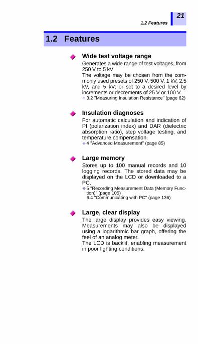
Generates a wide range of test voltages, from250 V to 5 kVThe voltage may be chosen from the com-monly used presets of 250 V, 500 V, 1 kV, 2.5kV, and 5 kV; or set to a desired level byincrements or decrements of 25 V or 100 V. 3.2 "Measuring Insulation Resistance" (page 62)
For automatic calculation and indication ofPI (polarization index) and DAR (dielectricabsorption ratio), step voltage testing, andtemperature compensation.4 "Advanced Measurement" (page 85)
Stores up to 100 manual records and 10logging records. The stored data may bedisplayed on the LCD or downloaded to aPC.5 "Recording Measurement Data (Memory Func-
tion)" (page 105)6.4 "Communicating with PC" (page 136)
The large display provides easy viewing.Measurements may also be displayedusing a logarithmic bar graph, offering thefeel of an analog meter.The LCD is backlit, enabling measurementin poor lighting conditions.
1.2 Features
Wide test voltage range
Insulation diagnoses
Large memory
Large, clear display

1.2 Features
22
The instrument has a USB interface. Datastored in the memory may be downloadedto PC using the data download software.The same software also enables reports tobe created and printed with ease. 6.4 "Communicating with PC" (page 136)
The case is durable-designed to withstandthe toughest of working conditions, com-pact, and highly portable.
The instrument can be powered by eitheralkaline or rechargeable nickel-hydrogenbatteries. (Selectable via switch)2.1.1 "Installing or Replacing the Battery" (page
36)2.1.2 "Installing the Battery Pack (Rechargeable nickel-hydrogen battery)" (page 39)
PC software with report creation/printing feature
Compact hard case
Dual battery power supply

1.3 Measurement Overview
1
2
3
4
5
6
7
8
9
10
11
付録
索引
23
This instrument is designed for measurement of the follow-ing:
Measurement conditionWhen measuring insulation resistance, ensure that powersupply to the object under test is turned off.
You will need:• IR3455 HIGH VOLTAGE INSULATION TESTER• AA alkaline batteries (LR6), or
9459 BATTERY PACK• 9750-01,-02,-03 TEST LEAD• 9751-01,-02,-03 ALLIGATOR CLIP• 9631-01,-05 TEMPERATURE SENSOR (for temperature
measurement)
Flow of measurement
Before starting measurement, check the following:• The power supply method.• The power ON/OFF method.• That date and time are set.• Connection of test leads, temperature sensor, and USB
cable.
1.3 Measurement Overview
Purpose : Inspection of high-voltage electrical facilities
Location : High-voltage receiving station or trans-forming station
Test object : Large motors, transformers, cables, etc.
• Measures insulation resistance, voltage and tem-perature.
• Stores measurement data in the internal memory.• Downloads data to a PC for table, graph, or report
creation.
Prepare for measurement2 "Measurement Preparations" (page 35)

1.3 Measurement Overview
24
Insulation Resistance Measurement3.2 "Measuring Insulation Resistance" (page 62)
Start measurement.
1. Make sure that power supply to the object undertest is turned off.
2. Press the key to turn onthe instrument.
2.2 (page 50)
3. Connect the test leads into the"+" and "-" terminals of the instru-ment and to the object to betested.
2.4 (page 56)3.2.1 (page 64)
GUARDterminal
Warning: Confirm that the power supply to the object under test has been turned off.
Object to be measured (Ex.: Motor)
+ terminal - terminal
Test lead (Red)Attach to a metal chassis or a ground terminal.
Test lead (Black)Attach to a metal part of the power supply terminal.

1.3 Measurement Overview
1
2
3
4
5
6
7
8
9
10
11
付録
索引
25
4. Press the key and set the test voltage.
3.2.1 (page 64)
5.Press the key to gener-
ate a voltage and start measure-ment.
3.2.1 (page 64)
6. Read the indication. 3.2.1 (page 64)
1.3 Measurement Overview
26
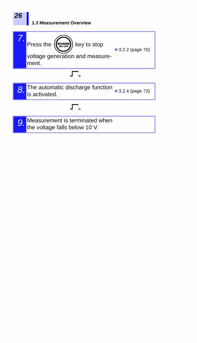
7.Press the key to stop
voltage generation and measure-ment.
3.2.2 (page 70)
8. The automatic discharge functionis activated. 3.2.4 (page 73)
9. Measurement is terminated whenthe voltage falls below 10 V.

1.3 Measurement Overview
1
2
3
4
5
6
7
8
9
10
11
付録
索引
27
Voltage Measurement
3.3 "Measuring Voltage" (page 79)1. Connect the test leads into the "+" and "-" termi-nals of the instrument and to the object to betested.
2. Read the indication.
+ terminal
- terminal
GUARDterminal
Test lead (Red) Test lead (Black)

1.3 Measurement Overview
28
Temperature Measurement
3.4 "Measuring Temperature" (page 82)Insulation resistance and temperature measurement dataare held after measurement is completed.This data will be cleared if power is turned off. To store thedata, use the memory function.
1. Insert the temperature sensor into the tempera-ture sensor terminal of the instrument.
2. Read the indication.
3. Press the key to stop temperature mea-surement.
Record measurement data5 "Recording Measurement Data (Memory Function)"

1.4 Names and Functions of Parts
1
2
3
4
5
6
7
8
9
10
11
付録
索引
29
1.4 Names and Functions of Parts
1. 2.
3.
LCD
Slide the shutter.
Operating panel (page 31)
4.
5 67
(page 9, page 45)
(page 9, page 56)
Front

1.4 Names and Functions of Parts
30
Name Function
1 AC adapter terminal
Connect the AC adapter to this terminal.2.1.3 "Connecting the AC Adapter" (page
45)
2 USB terminalConnect the USB Cable to this terminal.6.4.3 "Downloading Data to Save to PC/
Setting up Instrument on PC" (page 139)
3Temperature sensor terminal
Connect the temperature sensor to this termi-nal.2.5 "Connecting Temperature Sensor"
(page 58)
4 ShutterPrevents connection to other terminals when test leads are connected to the measurement terminals - a safety feature.
5 + measurement terminal*
Connect the red test lead to this terminal.2.4 "Connecting Test Lead" (page 56)
6 - measurement terminal*
Connect the black test lead to this terminal.2.4 "Connecting Test Lead" (page 56)
7 GUARDterminal
Connect the blue test lead to this terminal.3.2.7 "Use of GUARD Terminal" (page 77)
*These are referred to simply as + and - terminals.Back
Battery cover
Set screwBattery pack compartment(Under the battery cover)
Battery selector switch(Under the battery cover)Selects the type of battery.
AA alkaline batteries (LR6) compartment(Under the battery cover)
(page 9, page 36, page 39)

1.4 Names and Functions of Parts
1
2
3
4
5
6
7
8
9
10
11
付録
索引
31
Key Function
1 Used to turn power on/off.
2Used to set parameters.
Used to toggle between set voltage and monitor voltage after resistance measurement.
3Used to set parameters.
Used to set test voltage.
4
• Used to make fine adjustments to test voltage.• Used to move the cursor to change units, val-
ues, etc.
• Used to display the date and time.• Used to set the date and time.
5
• Used to make fine adjustments to test voltage.• Used to move the cursor to change units, val-
ues, etc.
• Used to display the timer.• Used to set the timer.
6 • Used to confirm entries.• Used to stop temperature measurement.
Operating panel
6. 7.
2.
1.
8. 9. 10.
13.
14.
15.
11.12.
5.3.4.
1.4 Names and Functions of Parts
32
Key Function
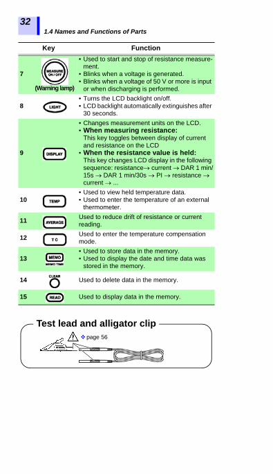
7
(Warning lamp)
• Used to start and stop of resistance measure-ment.
• Blinks when a voltage is generated.• Blinks when a voltage of 50 V or more is input
or when discharging is performed.
8• Turns the LCD backlight on/off.• LCD backlight automatically extinguishes after
30 seconds.
9
• Changes measurement units on the LCD.• When measuring resistance:
This key toggles between display of current and resistance on the LCD
• When the resistance value is held:This key changes LCD display in the following sequence: resistance current DAR 1 min/15s DAR 1 min/30s PI resistance current ...
10• Used to view held temperature data.• Used to enter the temperature of an external
thermometer.
11 Used to reduce drift of resistance or current reading.
12 Used to enter the temperature compensation mode.
13• Used to store data in the memory.• Used to display the date and time data was
stored in the memory.
14 Used to delete data in the memory.
15 Used to display data in the memory.
Test lead and alligator clippage 56
1.5 Screen Setup
1
2
3
4
5
6
7
8
9
10
11
付録
索引
33
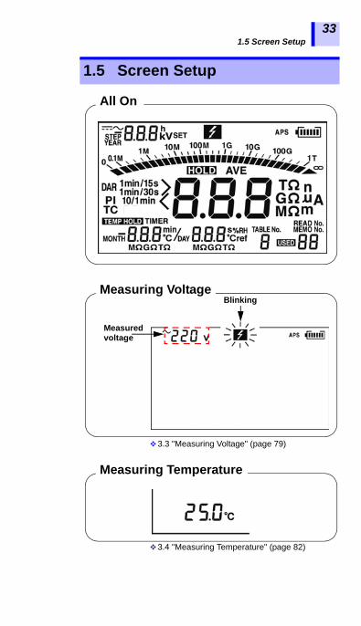
3.3 "Measuring Voltage" (page 79)
3.4 "Measuring Temperature" (page 82)
1.5 Screen Setup
All On
Measuring Voltage
Measured voltage
Blinking
Measuring Temperature

1.5 Screen Setup
34
3.2 "Measuring Insulation Resistance" (page 62)
3.2.5 "Switching to Leakage Current Indication" (page 74)
Measuring Insulation Resistance
Actual output voltage
Blinking
> blinks if the input exceeds the measure-ment range.
Elapsed time Insulation resistance
The screen is switched over with the
key.
Leakage Current DisplayBlinking
Elapsed time
Actual output voltage
The bar graph shows the resistance measurement.
< blinks at below 1 nA.
Current measurement

2.1 Supplying Power
1
2
3
4
5
6
7
8
9
10
11
付録
索引
35
This instrument can be powered by the following:• AA alkaline batteries (LR6)See 2.1.1 "Installing or Replacing the Battery" (page 36).• 9459 BATTERY PACK (Option)See 2.1.2 "Installing the Battery Pack (Rechargeable nickel-hydro-
gen battery)" (page 39), and 2.1.4 "Charging the Battery Pack" (page 47)
• 9753 AC ADAPTER (Option)See 2.1.3 "Connecting the AC Adapter" (page 45).
Measurement Preparations 22.1 Supplying Power

2.1 Supplying Power
36
2.1.1 Installing or Replacing the Battery
• To avoid electric shock, turn off thepower switch and disconnect the testleads before replacing the batteries.
• Do not mix old and new batteries, or dif-ferent types of batteries. Also, be care-ful to observe battery polarity duringinstallation. Otherwise, poor perfor-mance or damage from battery leakagecould result.
• After replacing the batteries, reattachthe battery cover and secure the screwbefore using the instrument.
• Battery may explode if mistreated. Donot short-circuit, recharge, disassembleor dispose of in fire.
• Handle and dispose of batteries inaccordance with local regulations.
• When the battery status indicatoris low, replace the batteries.
• The indicator lights up when theremaining battery capacity is low. In thiscase, measurement is not possible.Replace the batteries.
• Use the specified batteries only. Do not usemanganese batteries, for example, sinceoperating time will be greatly reduced.
• To avoid corrosion and damage to thisinstrument from battery leakage, removethe batteries from the instrument if it is tobe stored for a long time.

2.1 Supplying Power
1
2
3
4
5
6
7
8
9
10
11
付録
索引
37
Procedure
1. Turn off power and disconnect all thetest leads from the instrument.See 2.2 "Turning Power On and Off" (page 50).
2. Loosen the set screw on the rear of theinstrument and remove the batterycover.
3. Place six LR6 alkaline batteries into thebattery compartment. (Replace all six atthe same time)
Set screw
Remove
Battery cover

2.1 Supplying Power
38
4. Turn the battery selector switch to LR6.When the power is turned on, “Lr6” appearson the top left of the screen.See 2.2 "Turning Power On and Off" (page 50).
5. Replace the battery cover and tightenthe set screw.
To LR6
2.1 Supplying Power
1
2
3
4
5
6
7
8
9
10
11
付録
索引
39
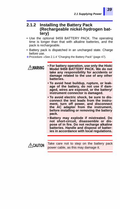
2.1.2 Installing the Battery Pack (Rechargeable nickel-hydrogen bat-tery)
• Use the optional 9459 BATTERY PACK. The operatingtime is longer than that with alkaline batteries, and thepack is rechargeable.
• Battery pack is dispatched in an uncharged state. Chargebefore use.
ProcedureSee 2.1.4 "Charging the Battery Pack" (page 47).
• For battery operation, use only the HiokiModel 9459 BATTERY PACK. We do nottake any responsibility for accidents ordamage related to the use of any otherbatteries.
• To avoid heat buildup, rupture, or leak-age of the battery, do not use if dam-aged, wires are exposed, or the battery/instrument connector is damaged.
• To avoid electric shock, be sure to dis-connect the test leads from the instru-ment, turn off power, and disconnectthe AC adapter from the instrument,before installing or removing the batterypack.
• Battery may explode if mistreated. Donot short-circuit, disassemble or dis-pose of in fire. Do not recharge alkalinebatteries. Handle and dispose of batter-ies in accordance with local regulations.
Take care not to step on the battery packpower cable, as this may damage it.
2.1 Supplying Power
40
Installation Procedure
Tools: Phillips screwdriver
1. Turn off power and disconnect the test leads,AC adapter and USB cable from the instru-ment.See 2.2 "Turning Power On and Off" (page 50).
• If the battery pack is not used for anextended period of time, remove it from theinstrument and store at a temperaturebetween -20 to 30°C, to preventdeterioration.Charge the battery at least every 2 months.If the battery pack is left for a long period oftime in a low state of charge, itsperformance will be degraded.
• When the battery status indicator is low,charge the battery pack.
• The battery pack is subject to self-discharge. Be sure to charge the batterypack before initial use. If the batterycapacity remains very low after correctrecharging, the useful battery life is at anend.
• The life of the battery pack is 500charging cycles, i.e., about one year.

2.1 Supplying Power
1
2
3
4
5
6
7
8
9
10
11
付録
索引
41
2. Loosen the set screw on the rear of theinstrument and remove the batterycover.
3. Connect the battery pack to the instru-ment. (Align the protrusions.)
Set screw
Remove
Battery cover

2.1 Supplying Power
42
4. Place the battery pack in the batterypack compartment.
5. Turn the battery selector switch to 9459.When the power is turned on, “bP” appearson the top left of the screen.See 2.2 "Turning Power On and Off" (page 50).
6. Replace the battery cover and tighten theset screw.(Be careful not to catch the battery packcable in the battery cover, to preventdamaged wiring.).
To 9459

2.1 Supplying Power
1
2
3
4
5
6
7
8
9
10
11
付録
索引
43
Replacement Tools: Phillips screwdriver
Procedure1. Turn off power and disconnect the testleads, AC adapter, and USB cable fromthe instrument.See 2.2 "Turning Power On and Off" (page 50).
2. Loosen the set screw on the rear of theinstrument and remove the batterycover.
3. Disconnect the plug of the battery packfrom the connector of the instrument.
Set screw
Remove
Battery cover

2.1 Supplying Power
44
4. Connect the new battery pack to the instru-ment. (Align the protrusions.)
5. Place the battery pack in the batterypack compartment.
6. Turn the battery selector switch to 9459.When the power is turned on, “bP” appearson the top left of the screen.See 2.2 "Turning Power On and Off" (page 50).
7. Place the battery cover and tighten thescrew.
To 9459

2.1 Supplying Power
1
2
3
4
5
6
7
8
9
10
11
付録
索引
45
2.1.3 Connecting the AC Adapter• Optional 9753 AC ADAPTER can be used.• When the AC adapter is connected to the instrument, you
can charge the battery pack, communicate with a PC, per-form temperature measurement, and edit the settings.However, you cannot measure insulation resistance, leak-age current or voltage.
Procedure
• Turn the instrument off before connect-ing the AC adapter to the instrumentand to AC power.
• Use only the specified Model 9753 ACADAPTER. AC adapter input voltagerange is 100 V to 240 V AC at 50 Hz/60Hz. To avoid electrical hazards and dam-age to the instrument, do not apply volt-age outside of this range.
• To avoid electrical accidents and tomaintain the safety specifications ofthis instrument, connect the power cordprovided only to an outlet.
The AC adapter cannot be used whenperforming measurement using instrumentleads.
1
2 Move the shutter.
34

2.1 Supplying Power
46
1. Insert the power cord into the ACadapter.
2. Move the shutter of the instrument toreveal the AC adapter terminal.
3. Insert the output cable of the AC adapterinto the AC adapter terminal.
4. Make sure that the commercial powersource voltage matches the rated supplyvoltage of the AC adapter. Insert theplug into the AC outlet.
When the AC adapter is connected to the instrument,power is supplied from the AC adapter.When both the battery and the AC adapter are con-nected to the instrument, the battery is not used.If the battery pack is installed, when the AC adapter isconnected to the instrument, power of the instrument isautomatically turned on and charging of the battery packbegins.
2.1 Supplying Power
1
2
3
4
5
6
7
8
9
10
11
付録
索引
47
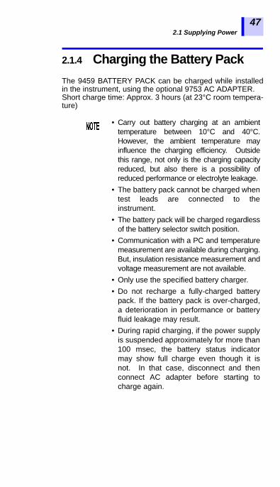
2.1.4 Charging the Battery PackThe 9459 BATTERY PACK can be charged while installedin the instrument, using the optional 9753 AC ADAPTER.Short charge time: Approx. 3 hours (at 23°C room tempera-ture)
• Carry out battery charging at an ambienttemperature between 10°C and 40°C.However, the ambient temperature mayinfluence the charging efficiency. Outsidethis range, not only is the charging capacityreduced, but also there is a possibility ofreduced performance or electrolyte leakage.
• The battery pack cannot be charged whentest leads are connected to theinstrument.
• The battery pack will be charged regardlessof the battery selector switch position.
• Communication with a PC and temperaturemeasurement are available during charging.But, insulation resistance measurement andvoltage measurement are not available.
• Only use the specified battery charger.• Do not recharge a fully-charged battery
pack. If the battery pack is over-charged,a deterioration in performance or batteryfluid leakage may result.
• During rapid charging, if the power supplyis suspended approximately for more than100 msec, the battery status indicatormay show full charge even though it isnot. In that case, disconnect and thenconnect AC adapter before starting tocharge again.

2.1 Supplying Power
48
Procedure
1. Install the battery pack.See 2.1.2 "Installing the Battery Pack
(Rechargeable nickel-hydrogen battery)" (page 39).
2. Move the shutter to reveal the ACadapter terminal.
3. Connect the AC adapter to the ACadapter terminal.
Rapid charging begins. During rapid charg-ing, the battery status indicator blinks.
See 2.1.3 "Connecting the AC Adapter" (page 45).
Move the shutter.
1
23
Battery status indicator
Charging
2.1 Supplying Power
1
2
3
4
5
6
7
8
9
10
11
付録
索引
49
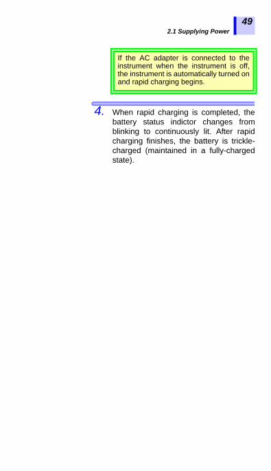
4. When rapid charging is completed, thebattery status indictor changes fromblinking to continuously lit. After rapidcharging finishes, the battery is trickle-charged (maintained in a fully-chargedstate).
If the AC adapter is connected to theinstrument when the instrument is off,the instrument is automatically turned onand rapid charging begins.

2.2 Turning Power On and Off
50
Press and hold the key for
around one second.After all the screen indications light, theversion and the position of the batteryselector switch appear and then theinstrument enters the standby state.
The instrument recalls the settings thatwere present before power was last turnedoff.
Press the key.
The screen is switched off and power isturned off.
2.2 Turning Power On and Off
Turning power On
Indicates the position of the battery selector switch.bP: Using the Model 9459 BATTERY PACKLr6: Using the LR6 alkaline batteries
Version
When the battery status indicatoris low, replace the battery.See 2.1.1 "Installing or Replacing the Battery"
(page 36).If the batteries or the battery pack is runninglow, [LObAt] is indicated. The instrumentturns off if use is continued.
Turing power off

2.2 Turning Power On and Off
1
2
3
4
5
6
7
8
9
10
11
付録
索引
51
2.2.1 Auto Power Off
• Power is automatically turned off around10 minutes after the last operation. Thisfunction, however, is not available duringinsulation resistance measurement.
• [APS] will start blinking around 30 sec-onds before power is turned off.
• Auto power off is re-enabled upon turningpower on again. ([APS] lights up.)
• When the AC adapter is connected to theinstrument, auto power off is disabled.
• When the timer is set or when the instru-ment is in the step voltage test mode,auto power off is disabled.
Turn on power while holding down the key.
Canceling Auto Power Off

2.3 Setting and Checking Date and Time
52
Set the time and date before use of the instrument. Use theGregorian calendar.
2.3.1 Setting Date and Time
Procedure
1. When the instrument is in a standby state,
press the key. Year, month, and dayappear.
2. Hold down key for more than one
second. The Year starts blinking.
2.3 Setting and Checking Date and Time

2.3 Setting and Checking Date and Time
1
2
3
4
5
6
7
8
9
10
11
付録
索引
53
3. Pressing moves the blinkingcursor. Place the cursor at the digit,value, etc., you wish to change.Year, month, day, hour, and minutes canbe changed.
The year-month-day screen and the hour-minute-second screen are switched to andfrom each other in the procedure below.
4. Press to change the number.Hold down for fast increase/decrease.
5. The entry is confirmed by pressing the
key, after which the display returnsto the standby screen.
The clock starts to run from zero seconds
as soon as key is pressed.
Year-month-day
Hour-minute-second
• When year [YEAR] is
blinking, press the key.
• When day [DAY] is blink-
ing, press the key.
Hour-minute-second
Year-month-day
• When hour [h] is blink-
ing, press the key.• When minute [min] is
blinking, press the key.
2.3 Setting and Checking Date and Time
54
• The date and time can be set on a PCusing the data analysis software formodel 3455.
• The data analysis software for model3455 must be installed on the PC.
Details See 6.4 "Communicating with PC" (page 136).
Date and time can be set on a PC.

2.3 Setting and Checking Date and Time
1
2
3
4
5
6
7
8
9
10
11
付録
索引
55
2.3.2 Checking Date and Time
Procedure
1. When the instrument is in the standby
state, press the key.Year, month, and day appear.
2. Press the key.
Hours, minutes, and seconds appear.
3. Pressing key returns to the standby
screen.

2.4 Connecting Test Lead
56
Procedure
1. Connect the alligator clip to the end ofeach test lead. Insert it fully.
2.4 Connecting Test Lead
• To avoid electrical accidents, removepower from the circuit before connect-ing the test leads.
• To avoid electric shock, never use theinstrument if the shutter is broken.
Only use Hioki-specified test leads withthe instrument. Safe measurement is notpossible with other cords.
Test leads cannot be connected to theinstrument if the AC adapter, a temperaturesensor, or USB cable is connected.

2.4 Connecting Test Lead
1
2
3
4
5
6
7
8
9
10
11
付録
索引
57
2. Move the shutter to reveal the + and -terminals.
3. Connect the red test lead to the + terminaland the black test lead to the - terminal.For insulation resistance measurement,connect the blue test lead to the GUARDterminal if necessary.Check that the test leads are fullyinserted.
GUARD terminal See 3.2.7 "Use of GUARD Terminal" (page 77).
+ terminal - terminal
GUARDterminal
Test lead (Red) Test lead (Black)

2.5 Connecting Temperature Sensor
58
Procedure
1. Move the shutter to reveal the temperaturesensor terminal.
2. Connect the temperature sensor to thetemperature sensor terminal.Temperature measurement begins auto-matically.
2.5 Connecting Temperature Sensor
Temperature sensors may be damaged byhigh voltage or static electricity. Do notexpose the temperature sensor to excessiveimpact, or allow the cable to be bent, sincemalfunction or faulty connection may result.
Temperature sensors cannot be usedsimultaneously with test leads.
Move the shutter.
Temperature sensor terminal

3.1 Pre-Operation Inspection
1
2
3
4
5
6
7
8
9
10
11
付録
索引
59
Before using the instrument, verify that it oper-ates normally to ensure that no damageoccurred during storage or shipping. If you findany damage, contact your authorized Hioki dis-tributor or reseller.
Confirm that the instrument chassis, shut-ter, test leads, and clips are not damaged.Do not used if damaged.
Equipment• 20 M resistor that provides a voltage of
5 kV• High-voltage meter with an input resis-
tance of 1,000 M or more, and capableof measuring up to 5.5 kV DC
Measurement 33.1 Pre-Operation Inspection
Before using the instrument, make surethat the insulation on the test leads andcables is undamaged and that no bareconductors are improperly exposed.Using the product in such conditionscould cause an electric shock, so contactyour authorized Hioki distributor orreseller for replacements.
Make sure the terminals are clean and dry.Wipe with a dry cloth to remove anymoisture, since measurement errors mayresult if moisture is present.See 8.2 "Cleaning" (page 156).
Checking for damage
Checking test voltage and resistancereading

3.1 Pre-Operation Inspection
60
Inspection
Procedure1. Clip the resistor with the red and blacktest leads connected to the instrument.
2. Also, clip the resistor with the test lead ofthe high-voltage meter.
3. Set the test voltage of the instrument to [5.00 kV].See 3.2Measuring Insulation Resistance, Proce-
dure 5. (page 66) to (page 66).
4. Hold down key for more than
one second to start insulation resistancemeasurement.
5. Check to see if the reading of the high-volt-age meter is somewhere between 5 kV and5.5 kV.
6. Check to see if the voltage reading of theinstrument is somewhere between 5 kVand 5.5 kV.

3.1 Pre-Operation Inspection
1
2
3
4
5
6
7
8
9
10
11
付録
索引
61
7. Check to see if the insulation resistancereading of the instrument is 20 M.
8. Stop insulation resistance measurement.See 3.2.2 "Ending Measurement" (page 70).
9. Short-circuit the tips of the clips of thered and black test leads of the instru-ment.
10. Press the key to see if the test volt-
age setting is [5.00 kV].
11. Hold down the key for more than
one second to start insulation resistancemeasurement.
12. Check to see if the insulation resistancereading of the instrument is 0.00 M. If a problem exists, discontinue use ofthe instrument.
Insulation resistance
Voltage
3.2 Measuring Insulation Resistance
62
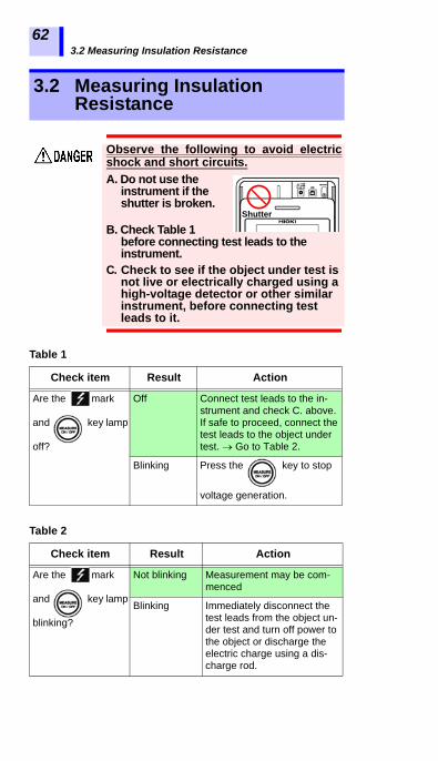
3.2 Measuring Insulation Resistance
Observe the following to avoid electricshock and short circuits.A. Do not use the
instrument if the shutter is broken.
B. Check Table 1 before connecting test leads to the instrument.
C. Check to see if the object under test is not live or electrically charged using a high-voltage detector or other similar instrument, before connecting test leads to it.
Table 1
Check item Result Action
Are the mark
and key lamp
off?
Off Connect test leads to the in-strument and check C. above. If safe to proceed, connect the test leads to the object under test. Go to Table 2.
Blinking Press the key to stop
voltage generation.
Table 2
Check item Result Action
Are the mark
and key lamp
blinking?
Not blinking Measurement may be com-menced
Blinking Immediately disconnect the test leads from the object un-der test and turn off power to the object or discharge the electric charge using a dis-charge rod.
Shutter

3.2 Measuring Insulation Resistance
1
2
3
4
5
6
7
8
9
10
11
付録
索引
63
• When measuring insulation resistance,dangerous voltage is applied to themeasurement terminals. To avoid elec-tric shock, do not touch the terminalsand test leads.
• Do not touch the object under test ordisconnect the test leads after measure-ment has been completed until the auto-matic discharge function is completed.Electric shock may result due to highvoltage and stored charge.See 3.2.4 "Automatic Discharge Function" (page
73).• Power of the instrument may be turned
off during measurement even if the key is not pressed, for instance,
due to battery consumption. In suchcase, the automatic discharge functionmay not operate. Discharge the objectunder test using a discharge rod forhigh voltage.
• To avoid damage to objects under test, besure to check the test voltage beforestarting measurement.
• When repeating measurement, press the
key before next measurement to checkthe test voltage.
• To avoid damage to the instrument duringdischarge, do not measure the insulationresistance between the terminals ofcapacitors (with a capacitance of over 4 F).
• To avoid damage to the instrument, do notshort-circuit the tips of the clips of the redtest lead (+ terminal) and the blue test lead(GUARD terminal).

3.2 Measuring Insulation Resistance
64
3.2.1 Starting Measurement
Procedure
1. Connect the alligator clip to the end ofeach test lead. Insert it fully.
2. Move the shutter to reveal the + and -terminals.

3.2 Measuring Insulation Resistance
1
2
3
4
5
6
7
8
9
10
11
付録
索引
65
3. Connect the red test lead to the + terminaland the black test lead to the - terminal.Connect the blue test lead to theGUARD terminal if necessary.Fully insert the test leads.See 3.2.7 "Use of GUARD Terminal" (page 77).
4. Clip the alligator clip at the end of eachtest lead to the object under test.
GUARDterminal
Warning: Confirm that the power supply to the object under test has been turned off.
Object to be measured (Ex.: Motor)
+ terminal - terminal
Test lead (Red)Attach to a metal chassis or a ground terminal.
Test lead (Black)Attach to a metal part of the power supply terminal.

3.2 Measuring Insulation Resistance
66
5. Press the key, after which the
voltage display starts blinking.
6. The test voltage is chosen from 250 V,500 V, 1.00 kV, 2.50 kV, and 5.00 kV
using the keys.
7. Pressing keys, you can makefine adjustment of the test voltage setting.
8. Press the key to set the test voltage.
The voltage indication will change fromblinking to continuous.This test voltage is now set.
For step voltage testing, hold downthe key, which will display[STEP]. For non-stepped insulationresistance measurement, press the
key and choose a voltage.

3.2 Measuring Insulation Resistance
1
2
3
4
5
6
7
8
9
10
11
付録
索引
67
9. Hold down the key for more than
one second.A voltage is generated and measurementbegins.
The mark and key lamp
starts blinking.
If > blinks, the input value is out of measurement range.Example: > 10.0 T means "larger than 10.0 T."• During measurement, [SET] is turned off in the voltage indica-
tion field and the indication changes from the set voltage tothe actual output voltage. A voltage approximately 5% higherthan the set level is output.
• To view the set voltage during measurement, press the key. The set voltage is displayed for approximately 2 seconds.
• During measurement, if the output voltage is lower than theset level, the voltage indication blinks.
• Under the resistance indication appears time elapsed from thestart of measurement.
Actual output voltage
Blinking
>blinks if the input exceeds the measurement range.
Elapsed time Insulation resistance

3.2 Measuring Insulation Resistance
68
10. Read the indication.
• If the indication is unstable, press the key. The average of the mea-
surements is shown.See "Average function" (page 69).• Resistance indication is switched to
leakage current indication by pressing
the key.See 3.2.5 "Switching to Leakage Current
Indication" (page 74).• When the timer has been set, remain-
ing time is displayed.See 4.1 "Using Timer" (page 85).
Do not allow test leads to contact each otheror place objects on test leads, to avoid mea-surement errors and malfunctions.
• Be sure to clean test leads after use. If testleads are soiled, they may deteriorate.
• Insulation resistance is unstable. Theindication may not stabilize with someobjects.
• Due to factors such as capacitance ofobjects under test, resistance values maystart low, then rise gradually and settle out.
• During measurement, if the resistance ofthe object suddenly drops or if the testlead tips are short-circuited, theinstrument stops voltage generation as asafety measure. (This applies to a testvoltage of 1.1 kV or more.)

3.2 Measuring Insulation Resistance
1
2
3
4
5
6
7
8
9
10
11
付録
索引
69
When the display reflects the followingstate, insulation resistance measurementcannot be started.• The setting value is blinking to indicate
that the instrument being set up
• The mark is blinking• While [TC] is lit, the actual measurement
temperature is shown as [- - -]• An error massage is displayed
If the indication is unstable, the average ofthe measurement is shown.
Pressing the key toggles [AVE] on/off.While [AVE] is on, display update interval isfour seconds, normally.But in the following case, the interval is onesecond even if [AVE] is on.• During 15 seconds after the measure-
ment started• During 5 to 10 seconds after the mea-
surement range changed
The state not to be started the measure-ment
Average function
3.2 Measuring Insulation Resistance
70
3.2.2 Ending Measurement
Procedure
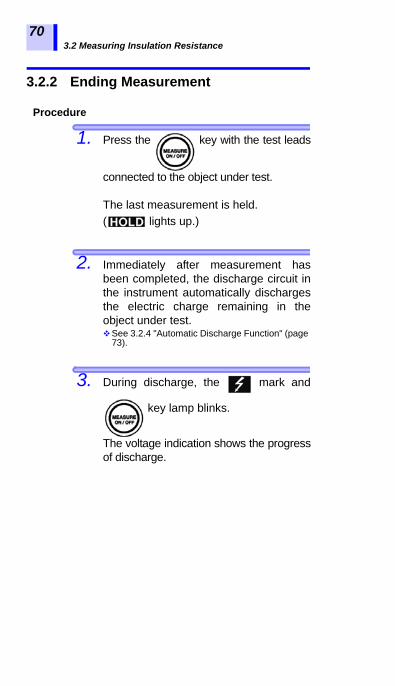
1. Press the key with the test leads
connected to the object under test.
The last measurement is held.( lights up.)
2. Immediately after measurement hasbeen completed, the discharge circuit inthe instrument automatically dischargesthe electric charge remaining in theobject under test.See 3.2.4 "Automatic Discharge Function" (page
73).
3. During discharge, the mark and
key lamp blinks.
The voltage indication shows the progressof discharge.

3.2 Measuring Insulation Resistance
1
2
3
4
5
6
7
8
9
10
11
付録
索引
71
4. When the voltage falls to about 10 V, the
instrument stops discharging and the
mark and key lamp are turned off.
5. To restart measurement, press the
key to check the set test voltage beforeresuming measurement.
• If the key is pressed during
measurement, automatic discharge isperformed before power is turned off.
• If the battery runs low during measure-ment, the instrument automaticallystops measurement. Automatic dis-charge is performed and then [LObAt]appears on the screen.
LastElapsed time of the
Actual outputvoltage(last measurement)
end of measurement measurement value
Check

3.2 Measuring Insulation Resistance
72
3.2.3 Checking and Deleting Held Data
The following data are held and displayed after insulationresistance measurement has been completed.• Insulation resistance (digital value and bar graph)• Test voltage• Actual output voltage• Leakage current• Elapsed time• DAR• PISome data may not be displayed. Press the keys shown inthe table below to switch the indication.
To clear the data, press the key for more than one sec-ond.Temperature/humidity data will not be cleared.
Checking Held Data
Data indications to be switched Keys used
key
key
Elapsed time Temperature/humidity(When the data are held) key
Insulation resistance
Leakage current
DAR 1 min/ 30 s
PI (10/1 min.)
DAR 1 min/15 s
Test voltage (setting)
Actual output voltage
The held data are cleared when power isturned off. To save the data, use thememory function.See 5 "Recording Measurement Data (Memory
Function)" (page 105).
Deleting Held Data

3.2 Measuring Insulation Resistance
1
2
3
4
5
6
7
8
9
10
11
付録
索引
73
3.2.4 Automatic Discharge Function
• When insulation resistance with a capacitance componentis measured, this component remains charged with ahigh-voltage equivalent to the test voltage, which is dan-gerous.
• This instrument automatically discharges remaining elec-tric charge using the internal circuit after measurement.
• Make sure that the test leads are connected to the measured
object when pressing the key to stop measure-
ment.
• Discharging stops when the residual voltage falls below 10V. The discharge time varies depending on the capacitance.
After the voltage has been decreased bythe instrument’s automatic discharge func-tion, the voltage in the measurement areamay rise again due to the remaining chargein the capacitor CA shown in the diagram insection 3.2.6. Take great care when touch-ing the object under test.

3.2 Measuring Insulation Resistance
74
3.2.5 Switching to Leakage Current Indi-cation
Insulation resistance indication may be switched to leakagecurrent indication.
Every time the key is pressed, theindication changes in the order: resistance current PI resistance etc.
Every time key is pressed, the indi-cation changes in the order: resistance current resistance current etc.
During measurementBlinking
Elapsed time
Actual output voltage
The bar graph shows the resistance measurement.
< blinks at below 1 nA.
Current measurement
Before measuring insulation resistanceand after setting test voltage( indicator is off.)
Measuring insulation resistance

3.2 Measuring Insulation Resistance
1
2
3
4
5
6
7
8
9
10
11
付録
索引
75
Every time key is pressed, the indi-cation changes in the order: resistance current DAR 1 min/15s DAR 1 min/30s PI resistance current etc.PI/DAR See 4.2 "Displaying PI and DAR"
(page 89).
3.2.6 Insulation Resistance Measurement Basis
When a high DC voltage is applied to an object under test, aleakage current flows.The insulation resistance instrument measures the appliedvoltage V and the combined leakage current I and then cal-culates the insulation resistance R.Calculation formula R = V/I
IC and IA gradually decrease after the volt-age is applied.
Holding data after measurement
If the indication is unstable, press the key. Theaverage of the measurements is shown.[< 1.00 nA] means "below 1.00 nA."

3.2 Measuring Insulation Resistance
76
When measuring the same object repeat-edly, the insulation resistance or leakagecurrent indications may differ. This is causedby polarization*, which occurs when a volt-age is applied to an insulating material. An insulating material is represented by anequivalent circuit as shown by the diagramon the previous page.Absorption current due to relatively slowpolarization is represented by IA, as shownin the diagram above. It takes time for thepolarization caused by the previous mea-surement disappear. Until it does, electriccharge remains in CA as shown in the dia-gram. The electric charge level in CA differsat the start of previous measurement and atthe start of next measurement and thusabsorption current IA differs, too. Further, thecombined leakage current and insulationresistance vary from measurement to mea-surement. This will be become more appar-ent for higher insulation resistance values.
To ensure reproducibility of measurement,leave a sufficient time interval between mea-surement sessions. Further, the ambienttemperature and humidity should not vary.
*Polarization: the phenomenon in which positive and negative charges on the atoms of a material move in opposite direc-tions causing a shift of the center when an electric field is applied to the material.
Reproducibility of insulation resistancemeasurement
3.2 Measuring Insulation Resistance
1
2
3
4
5
6
7
8
9
10
11
付録
索引
77
3.2.7 Use of GUARD Terminal
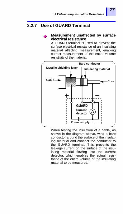
A GUARD terminal is used to prevent thesurface electrical resistance of an insulatingmaterial affecting measurement, enablingcorrect measurement of the entire volumeresistivity of the material.
When testing the insulation of a cable, asshown in the diagram above, wind a bareconductor around the surface of the insulat-ing material and connect the conductor tothe GUARD terminal. This prevents theleakage current on the surface of the insu-lating material flowing into the currentdetector, which enables the actual resis-tance of the entire volume of the insulatingmaterial to be measured.
Measurement unaffected by surfaceelectrical resistance
Metallic shielding layerBare conductor
Insulating material
Cable Core
Current detector
Power supply

3.2 Measuring Insulation Resistance
78
G terminal grounding is used for measuringthe insulation resistance between the coreand the metallic shielding layer of a high-voltage cable with the cable connected toother high-voltage equipment. The diagrambelow shows an example of measurement.
Rc: Insulation resistance of the insulatingmaterial of the high-voltage cable(Between core and metallic shieldinglayer)
Rs: Insulation resistance of the sheath ofthe high-voltage cable(Between metallic shielding layer andground)
Rn: Insulation resistance between insulatoror high-voltage equipment and ground
Influence of Rs and Rn is removed andsolely Rc is measured.
Reference High-voltage power receivingfacility code 2002
Measurement using G (GUARD) terminal grounding
Meter transformerDisconnector
Load
Core
RnRc
RsN
Remove
GroundingP
Power supply
wire
Cable
Powersupplyside
side
wireMetallic shielding layerof the cable
Current detector
3.3 Measuring Voltage
1
2
3
4
5
6
7
8
9
10
11
付録
索引
79
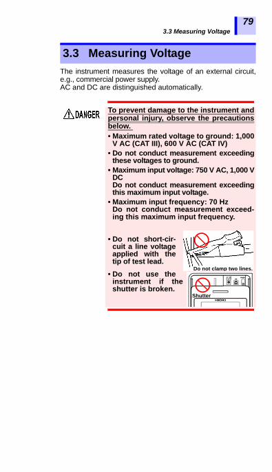
The instrument measures the voltage of an external circuit,e.g., commercial power supply.AC and DC are distinguished automatically.
3.3 Measuring Voltage
To prevent damage to the instrument andpersonal injury, observe the precautionsbelow. • Maximum rated voltage to ground: 1,000
V AC (CAT III), 600 V AC (CAT IV)• Do not conduct measurement exceeding
these voltages to ground.• Maximum input voltage: 750 V AC, 1,000 V
DCDo not conduct measurement exceedingthis maximum input voltage.
• Maximum input frequency: 70 HzDo not conduct measurement exceed-ing this maximum input frequency.
• Do not short-cir-cuit a line voltageapplied with thetip of test lead.
• Do not use theinstrument if theshutter is broken.
Do not clamp two lines.
Shutter

3.3 Measuring Voltage
80
Procedure
1. Connect alligator clips to the ends of testleads. Insert it fully.
2. Move the shutter to reveal the + and -terminals.
3. Connect the red test lead to the + termi-nal and the black test lead to the - termi-nal. Fully insert the test leads.
+ terminal
- terminal
GUARDterminal
Test lead (Red) Test lead (Black)

3.3 Measuring Voltage
1
2
3
4
5
6
7
8
9
10
11
付録
索引
81
4. Clip the ends of the test leads to the cir-cuit to be tested. When the voltage
exceeds 50 V, the mark and
key lamp blink.
5. Read the voltage indication.
The key is not used.
Measured voltage
Blinking

3.4 Measuring Temperature
82
3.4.1 Measurement Procedure
Procedure
1. Move the shutter to reveal the tempera-ture sensor terminal.
2. Connect the temperature sensor to thetemperature sensor terminal.
3.4 Measuring Temperature
Do not attempt to measure the tempera-ture of objects carrying a voltage. Doingso will result in a short-circuit accident oran electrocution accident.
Temperature sensors may be damaged byhigh voltage or static electricity. Do notexpose the temperature sensor to excessiveimpact, or allow the cable to be bent, sincemalfunction or faulty connection may result.
Move the shutter.
Temperature sensor terminal

3.4 Measuring Temperature
1
2
3
4
5
6
7
8
9
10
11
付録
索引
83
Temperature measurement begins auto-
matically.3. Read the temperature indication.
4. Press key or disconnect the tem-perature sensor to stop measurement.
lights up and the last mea-surement is held.
Detailing the above displaySee 6.3.2 "Clearing Indications of Temperature and Humidity Stored Data" (page 135).
After measuring temperature (When the resistance is not measured.)

3.4 Measuring Temperature
84
• If temperature measurement is stopped using the
key, measurement may be resumed by pressing
the key.• When an insulation resistance measurement is held, if
the temperature sensor is disconnected, the tempera-ture indication switches to the elapsed time indication atthe time of insulation resistance measurement. To dis-play the held temperature instead of the elapsed time,
press the key. (The temperature will blink.)
• Held measurement values are cleared when power isturned off. To save the data, use the memory function.
See 5.1.1 "Manual Recording (Recording result of one mea-surement session)" (page 107).
• Settings cannot be edited during temperature measure-ment. To edit settings, stop temperature measurement.
• [OF] means exceeding 70.0°C.[-OF] means below -10.0°C.
After measuring temperature (Disconnecting the temperature sensor, resistance value is held)

4.1 Using Timer
1
2
3
4
5
6
7
8
9
10
11
付録
索引
85
If the timer is set during insulation resistance measurement,the measurement automatically ends at the set time.Selectable time: 30 sec. to 30 min. (When setting over 1minute, time increments or decrements in minutes.)
4.1.1 Setting Timer/Conducting Insulation Resistance Measurement
Procedure
1. When the instrument is in a standby
state, press the key.
The time indication will blink.
2. Press the key to set the time.
Advanced Measurement 44.1 Using Timer
What is it used for? Used to set the instrument to auto-matically stop at a specified time.
4.1 Using Timer
86
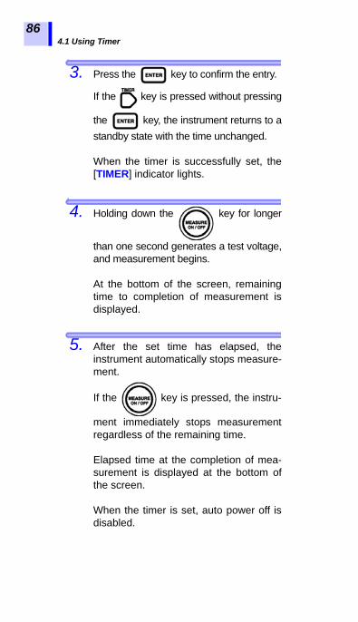
3. Press the key to confirm the entry.
If the key is pressed without pressing
the key, the instrument returns to astandby state with the time unchanged.
When the timer is successfully set, the[TIMER] indicator lights.
4. Holding down the key for longer
than one second generates a test voltage,and measurement begins.
At the bottom of the screen, remainingtime to completion of measurement isdisplayed.
5. After the set time has elapsed, theinstrument automatically stops measure-ment.
If the key is pressed, the instru-
ment immediately stops measurementregardless of the remaining time.
Elapsed time at the completion of mea-surement is displayed at the bottom ofthe screen.
When the timer is set, auto power off isdisabled.

4.1 Using Timer
1
2
3
4
5
6
7
8
9
10
11
付録
索引
87
Procedure
1. When the instrument is in a standby
state, press the key.
The time indication will blink.
2. Press the key to select - - min - - s.
- - min - - s is also selected by pressing
the key.
3. Press the key to confirm theentry.
[TIMER] indicator is turned off.
Timer not used

4.1 Using Timer
88
Procedure
1. When the instrument is in a standby
state, press the key.
The currently set time blinks. Check thetime.
2. Press the or key to return to the
previous screen.
Checking set time
4.2 Displaying PI and DAR
1
2
3
4
5
6
7
8
9
10
11
付録
索引
89
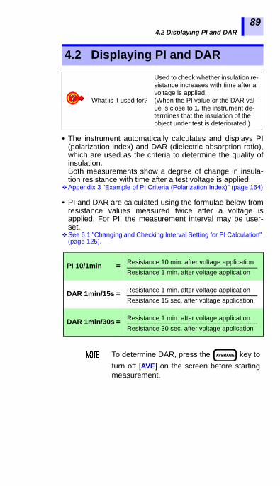
• The instrument automatically calculates and displays PI(polarization index) and DAR (dielectric absorption ratio),which are used as the criteria to determine the quality ofinsulation.Both measurements show a degree of change in insula-tion resistance with time after a test voltage is applied.
Appendix 3 "Example of PI Criteria (Polarization Index)" (page 164)
• PI and DAR are calculated using the formulae below fromresistance values measured twice after a voltage isapplied. For PI, the measurement interval may be user-set.
See 6.1 "Changing and Checking Interval Setting for PI Calculation" (page 125).
4.2 Displaying PI and DAR
What is it used for?
Used to check whether insulation re-sistance increases with time after a voltage is applied.(When the PI value or the DAR val-ue is close to 1, the instrument de-termines that the insulation of the object under test is deteriorated.)
PI 10/1min =
DAR 1min/15s =
DAR 1min/30s =
To determine DAR, press the key toturn off [AVE] on the screen before startingmeasurement.
Resistance 10 min. after voltage applicationResistance 1 min. after voltage application
Resistance 1 min. after voltage applicationResistance 15 sec. after voltage application
Resistance 1 min. after voltage applicationResistance 30 sec. after voltage application

4.2 Displaying PI and DAR
90
Procedure
1. Measure insulation resistance.
To determine PI, continue measurementfor 10 minutes (for a default time setting).To determine DAR, continue measurementfor one minute.
2. Stop measurement.
3. Press the key several times todisplay PI, DAR 1 min/15 s, or DAR 1min/30 s.
Every time the key is pressed theindication on the LCD changes in theorder of resistance current DAR 1min/15 s DAR 1 min/30 s PI resistance current , etc.

4.2 Displaying PI and DAR
1
2
3
4
5
6
7
8
9
10
11
付録
索引
91
• If measurement ends before the set timeelapses, [ - - - ] appears on the screen.
• When [TC] is on (temperature compensationmode), PI and DAR cannot be displayed.
• In the step voltage test mode, PI or DARcannot be displayed.
DAR
PI
Resistance
Right: 1st measurementLeft : 2nd measurement
Right: 1stLeft : 2nd
1st : 1 min.2nd : 10 min.
Measurement
ResistanceRight : 1st 30 GLeft : 2nd 60 G
Substitute into the formula; PI 10/1min=Resistance 10min. after voltage application divided by resistance 1min. after voltage application. PI in the example above is: 2.00=60.0 G / 30.0 G
Interval
Measurement Interval

4.2 Displaying PI and DAR
92
When the resistance indication blinks, thedisplayed reading may be incorrect. (Insu-lation resistance changed rapidly beforeend of set specified time, affecting mea-surement range so that the internal circuitfailure to respond)When the resistance reading blinks, regardthe PI or DAR value as a reference. Per-form measurement again.
The table below shows special indicationsfor PI and DAR.
Blinking resistance indication on PI orDAR display screen
PI, DAR Conditions
- - -
• One or more resistance val-ues could not be acquired.([- - -] appears in the resis-tance field.)
• One or more resistance val-ues exceeded measure-ment range.([OF] appears in the resis-tance field.)
• The 1st measurement was0.00 M.
>999 PI or DAR is larger than 999.
<0.01 PI or DAR is smaller than0.01.

4.3 Temperature Compensation (TC)
1
2
3
4
5
6
7
8
9
10
11
付録
索引
93
• The instrument converts measured resistance to theresistance at a reference temperature and displays theresult.
• There are 10 compensation methods (compensationtables) available depending on the object under test andits characteristics. Choose the appropriate temperaturecompensation table.
• The reference temperature may be set to an arbitrarylevel. The selectable reference temperature ranges varydepending on the compensation table used.
• The convertible measurement temperature ranges alsovary depending on the compensation table used.
See Appendix 4 "Temperature Compensation Table" (page 165).
4.3.1 Performing Temperature Compensa-tion
Procedure
1. Measure temperature and insulationresistance. The measurements are heldupon completion.(Either may be measured first.)3.2 "Measuring Insulation Resistance" (page 62)
See 3.4 "Measuring Temperature" (page 82).The temperature may also be entered withkeys.See 6.3 "Entering Temperature and Humidity
Measured with External Thermometer and Hygrometer" (page 131).
In the step voltage test mode ([STEP] is on),temperature compensation is unavailable.Exit the step voltage test mode.See 4.4.3 "Exiting Step Voltage Test Mode"
(page 103).
4.3 Temperature Compensation (TC)
What is it used for?
Used to acquire insulation resis-tance at a temperature differing from the actual temperature at which measurement is performed.

4.3 Temperature Compensation (TC)
94
2. Press the key.
[TABLE No.] blinks.
3. Choose a table No. from 0 to 9 using the
key.
4. Press the key to confirm the
choice of table No.The reference temperature blinks.
5. Adjust the reference temperature using
the key.
If the keys are held downsimultaneously, the reference tempera-ture is returned to its default.(40°C for table 9 and 20°C for the rest.)

4.3 Temperature Compensation (TC)
1
2
3
4
5
6
7
8
9
10
11
付録
索引
95
6. Press the key to confirm the ref-
erence temperature.[TC] lights up and the instrument enterstemperature compensation mode.The LCD displays the resistance at thereference temperature converted fromthe measurement.
The bar graph shows the value before com-pensation.
Bar graph(Value before compensation)
Digital value(Value after compensation)
Actual Measurement Temperature Reference Temperature
• If the resistance before compensationexceeds the measurement range, itcannot be converted and the LCDdisplays [- - -].
• After the instrument is placed intemperature compensation mode,measurement or input of temperature andmeasurement of insulation resistancemay be conducted.
• However, if the instrument is placed intemperature compensation mode whenthe temperature is not held (is off), measure or enter temperaturebefore measuring resistance. You cannotmeasure resistance first.

4.3 Temperature Compensation (TC)
96
Press the keys shown in the table below to switch the indi-cation.
4.3.2 Exiting Temperature Compensation Mode
Procedure Press the key.
[TC] is turned off and the instrumentexits temperature compensation mode.
• Resistance measured by the step voltagetest cannot be converted usingtemperature compensation.
• In temperature compensation mode,leakage current may be displayed by
pressing the key but it cannot becorrected for.
Indications to be switched Keys used
key
Temperature Reference temperature Elapsed time key
key
Insulation resistance (after compensation)
Leakage current(no compensation)
Setup screen of actual mea-surement temperature Standby state

4.4 Step Voltage Test
1
2
3
4
5
6
7
8
9
10
11
付録
索引
97
• The instrument increases the test voltagegradually and monitors the resultant insu-lation resistance and leakage current.
• If the insulation resistance decreases asthe test voltage increases, the objectunder test is damp or unclean andrequires attention. (Reference standard IEEE43-2000 Recommended Practice forTesting Insulation Resistance of RotatingMachinery)
• The test voltage is increased in 5 steps atregular intervals during insulation resis-tance measurement. The resistance mea-surement and the current measurementare acquired once at the end of everystep.
• The test voltage is applied in one of thetwo orders below.STEP2.50 kV: 500 V 1 kV 1.5 kV
2 kV 2.5 kVSTEP5.00 kV: 1 kV 2 kV 3 kV
4 kV 5 kV
4.4 Step Voltage Test
What is it used for?Used to determine the effect of the test voltage level on insulation resis-tance of an object.
What is a step voltage test?
Overview of test

4.4 Step Voltage Test
98
• The voltage is increased when one minute has passed at
each voltage step. When 5 minutes has passed in total,measurement automatically stops.• The voltage application time is adjustable.See 6.2 "Changing and Checking Voltage Application Time for Step
Voltage Test" (page 128).• The voltage application time cannot be varied for each
step.
4.4.1 Setting and Conducting a Step Voltage Test
Procedure
1. Press the key in standby state,
and the voltage indication will blink.
2. Press the key to choose
[STEP2.50 kVSET] or [STEP5.00 kVSET].• The voltage value will advance rapidly if
the key is held down.
• Choosing [5.00 kVSET] with the key
and then pressing the key is a short-cut to select STEP.
STEP5.00 kV
1 kV
2 kV
3 kV
4 kV
5 kV
1 min. 2 min. 3 min. 4 min. 5 min.
Measurement (1)
Measurement (2)
Measurement (3)
Measurement (4)
Measurement (5)
End of Measurement

4.4 Step Voltage Test
1
2
3
4
5
6
7
8
9
10
11
付録
索引
99
3. Press the key.The voltage indication will stop blinkingand the instrument enters the step volt-age test mode.
4. To start the step voltage test, hold down the
key for more than one second.
The mark and the key
start blinking, and insulation resistanceor leakage current appears on the
screen. (Press the key to togglebetween them.)
Lighting
Interval for1 step
Actual output
Elapsed time Step No.
voltage

4.4 Step Voltage Test
100
5. The test voltage rises at regular intervalsand the test stops automatically.
The last data is held and displayed.( lights up.)
Actual outputvoltage
Elapsed time at completionLast resistance measurement
• While [TC] is on (temperature compensa-tion mode), STEP cannot be selected.
Press the key to turn off the [TC]indicator.
• To view the set voltage during measure-
ment, press the key. The set voltageis displayed for approximately 2 seconds.
• After the test, pressing the keyswitches between the last output voltageand the test voltage.
• When the instrument is in the step voltagetest mode, auto power off is disabled.

4.4 Step Voltage Test
1
2
3
4
5
6
7
8
9
10
11
付録
索引
101
4.4.2 Viewing Detailed Data of Each Step after Step Voltage Test
Procedure
1. When the instrument is in standby state
after step voltage test, press the key.
will blink and the LCD displaysthe details of the step voltage test data.The first page shows the data at the testvoltage for step 1.
Actual output voltage at step 1 Blinking
Resistance at step 1
Elapsed time at end of step 1
Shows step No.

4.4 Step Voltage Test
102
2. To display other detailed data, use thefollowing keys.
Test voltage (setting) and actual outputvoltage are toggled automatically.
3. If the key is pressed on the
detailed data screen, the indica-tor changes from blinking to continu-ously lit and the LCD returns to thestandby screen.
Indications to be switched Keys used
Voltages and data at 5 steps key
Insulation resistance leakage current key
(Temperature and humidity are measured imme-diately before or after the test.)
key
Elapsed time to thestep currently displayed
Temperature/Humidity
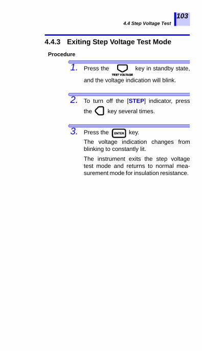
4.4 Step Voltage Test
1
2
3
4
5
6
7
8
9
10
11
付録
索引
103
4.4.3 Exiting Step Voltage Test ModeProcedure
1. Press the key in standby state,
and the voltage indication will blink.
2. To turn off the [STEP] indicator, press
the key several times.
3. Press the key.The voltage indication changes fromblinking to constantly lit.
The instrument exits the step voltagetest mode and returns to normal mea-surement mode for insulation resistance.

4.4 Step Voltage Test
104

1
2
3
4
5
6
7
8
9
10
11
付録
索引
105
The instrument stores measurement data, settings, date andtime in the internal memory.Data is not erased when the power is shut off.There are two recording methods. (Combinable)
• The content of a manual records are viewable on the LCDof the instrument.Further, the records can be downloaded to a PC using thePC software.
• For logging records, only the last value is viewable on theLCD of the instrument. The entire record is viewable on aPC using the PC software.See 6.4 "Communicating with PC" (page 136).
• Add data No. to data to record. The data No. serves as theaddress in the memory. The table shows the data No. num-bering system.
Recording Measurement Data(Memory Function) 5
Manual recording: Stores held data
Logging recording:
Stores insulation resistance data at regularintervals.
Recording method Data No.
Manual recording
A0 - A9, b0 - b9, C0 - C9, d0 - d9, E0 - E9, F0 - F9,H0 - H9, J0 - J9, n0 - n9, P0 - P9 (100 numbers in total)
Logging recording
Lr0 - Lr9 (10 numbers in total. Up to360 loggings per data No.)

106
• The table below shows storable data.
Recording method Type of data Data stored in one record:
record 1
Manual recording
Standard mea-surement data
(Data when neither [TC] nor [STEP] is on)
Data No., year/month/day/hour/minute/second (at the end of resistance measurement), elapsed time, temperature, humidity, test voltage (setting), actual output voltage, resis-tance (last) / (after 15 sec.) / (after 30 sec.) / (after 1 min.), PI, DAR (1 min/30 s), DAR (1 min/15 s), user-set interval for PI x 2, and, resistance at user-set interval x 2
Temperature compensation
data(Data when [TC]
is on)
Data No., year/month/day/hour/minute/second (at the end of resistance measurement), elapsed time, temperature, humidity,test voltage (set value), actual output voltage, resis-tance (last), Reference temperature,Resistance after compensation, and, table No.
Step voltage test data
(Data when [STEP] is on)
Data No., year/month/day/hour/minute/second (at the end of test), Step time, temperature, humid-ity, test voltage (set value),actual output voltage x 5, Resis-tance x 5
Logging recording - - - - - -
year/month/day/hour/minute/second (at the start of logging recording), Measuring interval,temperature, humidity,test voltage (set value),actual output voltage x 360 times,Resistance x 360 times
• In step voltage test resistance measurements,only the last measurement at the end of eachstep is recorded.
• Voltage measurement data cannot be recorded.• Temperatures are not stored as logging records.

5.1 Recording Measurement Data
1
2
3
4
5
6
7
8
9
10
11
付録
索引
107
5.1.1 Manual Recording (Recording result of one measurement session)
After measurement has been completed,store the data.
• The data numbers available for manualrecording are divided into 10 groups (10records per group), thus up to 100records can be stored.
• There are three types of data: standardmeasurement data, temperature compen-sation data, and step voltage test data.These three data sets are stored sepa-rately.
5.1 Recording Measurement Data
A0 - A9, b0 - b9, C0 - C9, d0 - d9, E0 - E9, F0 - F9, H0 - H9, J0 - J9, n0 - n9, P0 - P9
Operation Flow
Start measurement
Stop measurement
Set data No.
Store with the key.
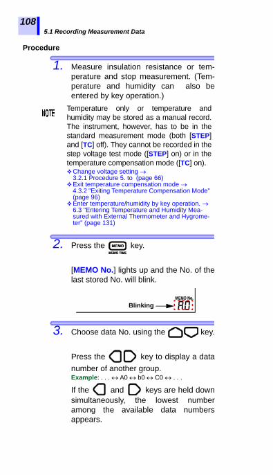
5.1 Recording Measurement Data
108
Procedure
1. Measure insulation resistance or tem-perature and stop measurement. (Tem-perature and humidity can also beentered by key operation.)
2. Press the key.
[MEMO No.] lights up and the No. of thelast stored No. will blink.
3. Choose data No. using the key.
Press the key to display a datanumber of another group.Example: . . . A0 b0 C0 . . .
If the and keys are held downsimultaneously, the lowest numberamong the available data numbersappears.
Temperature only or temperature andhumidity may be stored as a manual record.The instrument, however, has to be in thestandard measurement mode (both [STEP]and [TC] off). They cannot be recorded in thestep voltage test mode ([STEP] on) or in thetemperature compensation mode ([TC] on).Change voltage setting
3.2.1 Procedure 5. to (page 66)Exit temperature compensation mode
4.3.2 "Exiting Temperature Compensation Mode" (page 96)
Enter temperature/humidity by key operation. 6.3 "Entering Temperature and Humidity Mea-sured with External Thermometer and Hygrome-ter" (page 131)
Blinking

5.1 Recording Measurement Data
1
2
3
4
5
6
7
8
9
10
11
付録
索引
109
4. Press the key.
[MEMO No.] blinks and data is recorded.If a number with indicator is cho-sen, existing data will be overwritten withnew data.
• Temperature may be measured eitherbefore or after insulation resistancemeasurement.
• If is indicated for a data No., datais already recorded under the number. (Inmanual recording, data can beoverwritten.)
• If is not pressed and the
key is pressed, the LCD returns to theprevious screen without recording data.
• If step voltage test is stopped at any time,data cannot be recorded.
• If compensated resistance is indicated as[E11] in the temperature compensationmode, data cannot be recorded.
About [E11] 8.3 "Error Display" (page 156)• Do not turn off power while [MEMO No.] is
blinking. Data will be lost.

5.1 Recording Measurement Data
110
5.1.2 Logging Recording (Recording at regular intervals)
The instrument stores insulation resistance data at set inter-vals.• A total of 10 data numbers are used for logging records;
Lr0 to Lr9.• Each record contains up to 360 loggings.
Selectable recording intervals:15 sec., 30 sec., 1 min., 2 min., 5 min.
• Maximum number of loggings and maximum recordingtime vary depending on set recording interval.(The timer is off.)
• When the timer is set, the instrument automatically stopsmeasurement after the set time has elapsed.Selectable time: 30 sec. to 30 min. or OFF (When settingto more than 1 minute, the time increments or decrementsby 1 minute.)
w
Recording interval
Maximum number of loggings
Maximum recording time
15 sec. 360 times 90 min.30 sec. 360 times 3 hours 1 min. 360 times 6 hours 2 min. 250 times 8 hours and 20 min.5 min. 100 times 8 hours and 20 min.
• Continuous recording time is determinedby the battery charge level
• If the battery charge level becomes lowduring measurement, [LobAt] appearsand the instrument records themeasurement data to that point.
• When a low resistance is measured, morepower is consumed, thus the instrumentmay not be able to measure data equal tothe maximum number of loggings.
• We recommend the 9459 BATTERYPACK (optional) when performing loggingrecording, since this pack has a largercapacity.

5.1 Recording Measurement Data
1
2
3
4
5
6
7
8
9
10
11
付録
索引
111
Operation Flow
Set data No.See "Setting Data No." (page 112).
Set Recording interval.See "Setting Recording Interval" (page 114).
Set timer.See "Setting Timer" (page 114).
Start measurementSee "Measuring" (page 115).
Stop measurementSee "Measuring" (page 115).
Store in memory with the key.See "Recording the Data in Memory" (page
117).

5.1 Recording Measurement Data
112
• To exit the setup screen, press the key. No changes will be made to the set-tings.
• To exit the logging recording mode, press
the key.
When held data is displayed, loggingrecording cannot be selected.
Hold down the key for more than onesecond to erase the held data and then per-form the operation below.
Procedure
1. Press the key in standby state.[MEMO No.] lights up and the availableNo. next to the last stored No. blinks.
Exiting Setup Screen or Logging RecordingMode
Setting Data No.
Logging recording is not available in thestep voltage test mode (the voltage settingis STEP) or in the temperaturecompensation mode ([TC] is on).Change the voltage setting
3.2.1 Procedure 5. - (page 66)Exit temperature compensation mode.
4.3.2 "Exiting Temperature Compensation Mode" (page 96)
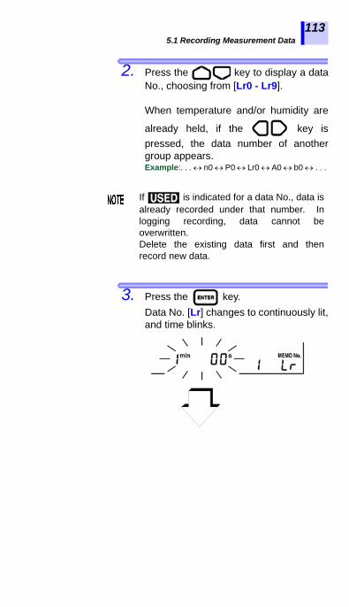
5.1 Recording Measurement Data
1
2
3
4
5
6
7
8
9
10
11
付録
索引
113
2. Press the key to display a dataNo., choosing from [Lr0 - Lr9].
When temperature and/or humidity are
already held, if the key ispressed, the data number of anothergroup appears.Example:. . . n0 P0 Lr0 A0 b0 . . .
3. Press the key.Data No. [Lr] changes to continuously lit,and time blinks.
If is indicated for a data No., data isalready recorded under that number. Inlogging recording, data cannot beoverwritten.Delete the existing data first and thenrecord new data.

5.1 Recording Measurement Data
114
Procedure
4. Press the key to display adesired recording interval.
5. Press the key.
6. The time changes from blinking to con-tinuous and the instrument enters thelogging recording mode.
7. Set the timer.(Selectable time: 30 sec. to 30 min. orOFF)
Press the key.
The [TIMER] indicator, time, and TIMERblink.
Setting Recording Interval
Setting Timer
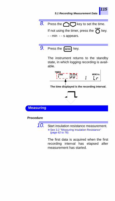
5.1 Recording Measurement Data
1
2
3
4
5
6
7
8
9
10
11
付録
索引
115
8. Press the key to set the time.
If not using the timer, press the key.- - min - - s appears.
9. Press the key.
The instrument returns to the standbystate, in which logging recording is avail-able.
Procedure
10. Start insulation resistance measurement.See 3.2 "Measuring Insulation Resistance"
(page 62 to 78)
The first data is acquired when the firstrecording interval has elapsed aftermeasurement has started.
The time displayed is the recording interval.
Measuring

5.1 Recording Measurement Data
116
11. Insulation resistance measurement stopsunder one of the three conditions below.1. Time equal to recording interval x maximum
number of loggings has elapsed.2. The set time of the timer has elapsed.
3. The key is pressed.
After measurement has been completed,the data No. blinks.Data is not stored in the memory at thispoint.
12. Measure temperature, if necessary. Thismay be omitted.Temperature and humidity measured withexternal thermometer and hygrometermay be entered by key operation.See 3.4 "Measuring Temperature" (page 82).See 6.3 "Entering Temperature and Humidity
Measured with External Thermometer and Hygrometer" (page 131).
• If measurement is stopped before thefirst recording interval elapses, no log-ging records are acquired and [MEMONo.] and the data No. are turned off.
• When the data No. blinks upon com-pletion of measurement, if [LObAt]appears due to low battery or if poweris turned off by the auto power off, thedata will be stored in the memory.
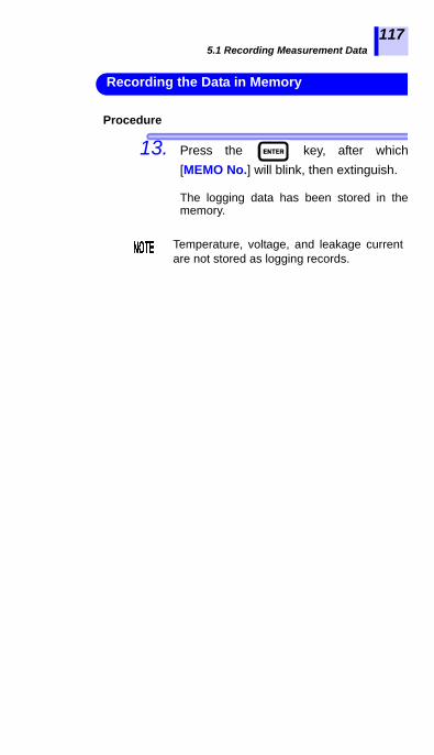
5.1 Recording Measurement Data
1
2
3
4
5
6
7
8
9
10
11
付録
索引
117
Procedure
13. Press the key, after which[MEMO No.] will blink, then extinguish.
The logging data has been stored in thememory.
Recording the Data in Memory
Temperature, voltage, and leakage currentare not stored as logging records.

5.2 Checking Recorded Data
118
• The content of a manual record is viewedon the LCD of the instrument.
• For logging records, only the last value isviewed on the LCD of the instrument. Theentire record is viewed on a PC using PCsoftware.
See 6.4 "Communicating with PC" (page 136).Procedure
1. Press the key in standby state.([MEMO No.] must be off.)
[READ No.] lights up and data No. anddata blink.
2. Press the key to choose theNo. of the data you wish to view. Thedata stored under the number appears.
Press the key to display thedata number of another group.Example: . . A0 b0 C0 . .
The recording method of the displayedrecord is identified as follows.
5.2 Checking Recorded Data
Data No. is not [Lr] Manual recording data
Data No. is [Lr] Logging recording data
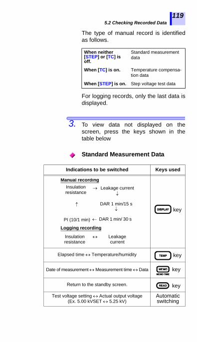
5.2 Checking Recorded Data
1
2
3
4
5
6
7
8
9
10
11
付録
索引
119
The type of manual record is identified
as follows.For logging records, only the last data isdisplayed.
3. To view data not displayed on thescreen, press the keys shown in thetable below
When neither [STEP] or [TC] is off.
Standard measurement data
When [TC] is on. Temperature compensa-tion data
When [STEP] is on. Step voltage test data
Standard Measurement Data
Indications to be switched Keys used
key
Elapsed time Temperature/humidity key
Date of measurement Measurement time Data key
Return to the standby screen. key
Test voltage setting Actual output voltage (Ex. 5.00 kVSET 5.25 kV)
Automatic switching
Insulation resistance
Leakage current
DAR 1 min/ 30 s
PI (10/1 min)
DAR 1 min/15 s
Manual recording
Logging recording
Insulation resistance
Leakage current

5.2 Checking Recorded Data
120
Temperature Compensation Data
Indications to be switched Keys used
key
key
Date of measurement Measurement time Data key
Return to the standby screen. key
Test voltage setting Actual output voltage (Ex. 5.00 kVSET 5.25 kV)
Automatic switching
key
The leakage current and the bar graphdisplayed as temperature compensationdata are those before compensation.
Insulation resistance (after compensation)
Leakage current(no compensation)
Elapsed time Actual measurement temperature/ Reference temperature
Resistance before compensation
Resistance after compensation
Actual measurement temperature/Humidity
Reference temperature/Table number
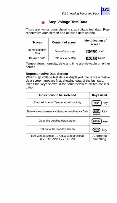
5.2 Checking Recorded Data
1
2
3
4
5
6
7
8
9
10
11
付録
索引
121
There are two screens showing step voltage test data; Rep-resentative data screen and detailed data screen.
Temperature, humidity, date and time are viewable on eitherscreen.
Representative Data ScreenWhen step voltage test data is displayed, the representativedata screen appears first, showing data of the last step.Press the keys shown in the table below to switch the indi-cation.
Step Voltage Test Data
Screen Content of screen Identification of screen
Representative data Data of last step is off.
Detailed data Data of every step blinks
Indications to be switched Keys used
Elapsed time Temperature/Humidity key
Date of measurement Measurement time Data key
Go to the detailed data screen. key
Return to the standby screen. key
Test voltage setting Actual output voltage (Ex. 5.00 kVSET 5.25 kV)
Automatic switching
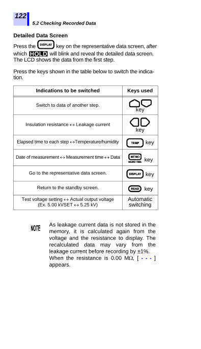
5.2 Checking Recorded Data
122
Detailed Data Screen
Press the key on the representative data screen, after which will blink and reveal the detailed data screen. The LCD shows the data from the first step.
Press the keys shown in the table below to switch the indica-tion.
Indications to be switched Keys used
Switch to data of another step. key
Insulation resistance Leakage current key
Elapsed time to each step Temperature/humidity key
Date of measurement Measurement time Data key
Go to the representative data screen. key
Return to the standby screen. key
Test voltage setting Actual output voltage (Ex. 5.00 kVSET 5.25 kV)
Automatic switching
As leakage current data is not stored in thememory, it is calculated again from thevoltage and the resistance to display. Therecalculated data may vary from theleakage current before recording by ±1%. When the resistance is 0.00 M, [ - - - ]appears.

5.3 Deleting Recorded Data
1
2
3
4
5
6
7
8
9
10
11
付録
索引
123
5.3.1 Deleting Data of Chosen No.
Select the data to be deleted, and delete only this selection.
Procedure
1. Press the key in standby state.
2. Press the key to display the num-ber of the data to delete.
3. Press the key.
[CLr] appears.
4. After pressing the key, [CLr]blinks and the data is deleted.
5.3 Deleting Recorded Data
If the key is pressed without the
key being pressed, the LCDreturns to the previous screen withoutdeleting the data.

5.3 Deleting Recorded Data
124
5.3.2 Deleting all Data
Delete all the manual records and logging records simulta-neously.
Procedure
1. Press the key in a standby state.
2. Press the key twice.
[ALL CLr] appears.
3. Press the key, and [ALL CLr]blinks and all the data are deleted.
If the key is pressed without the
key being pressed, the LCDreturns to the previous screen withoutdeleting the data.
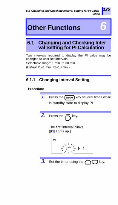
6.1 Changing and Checking Interval Setting for PI Calcu-lation
1
2
3
4
5
6
7
8
9
10
11
付録
索引
125
Two intervals required to display the PI value may bechanged to user-set intervals.Selectable range: 1 min. to 30 min.(Default t1=1 min., t2=10 min.)
6.1.1 Changing Interval Setting
Procedure
1. Press the key several times while
in standby state to display PI.
2. Press the key.
The first interval blinks.([t1] lights up.)
3. Set the timer using the key.
Other Functions 66.1 Changing and Checking Inter-
val Setting for PI Calculation

6.1 Changing and Checking Interval Setting for PI Calcu-lation
126
4. Press the key.
The first interval is confirmed and thesecond interval will blink. ([t2] lights up.)
5. Set the timer using the key.The 2nd interval must be longer than the1st interval.
6. Press the key.
The 2nd interval is confirmed and theLCD returns to the PI display screen.Setting of intervals has been completed.
• The intervals can be set up on a PC usingthe data analysis software for 3455.
• The data analysis software for 3455 mustbe installed on the PC.
Details See 6.4 "Communicating with PC" (page 136).
• When the intervals are not at their defaults, [10/1 min] isoff on the PI display screen.
• If insulation resistance is measured in this state, theinstrument displays PI calculated from resistance mea-surements at the set intervals.
• After the interval setting has been changed, PI of thedata measured before the change cannot be displayed.
• If the key is pressed during setting, the instrumentreturns to a standby state without changing the setting.
The intervals can also be set up on a PC.
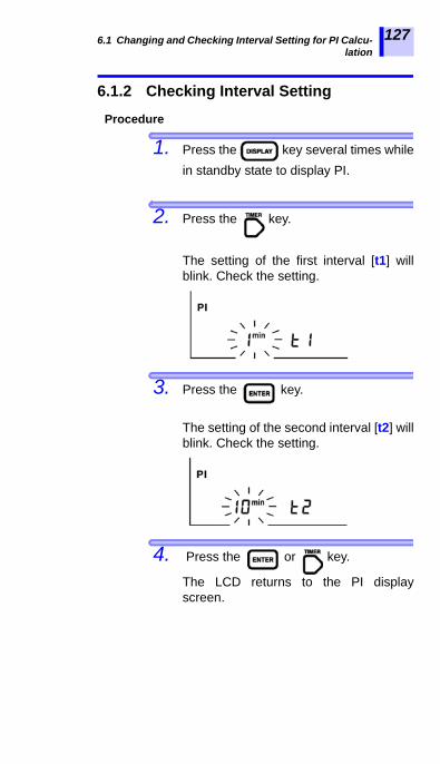
6.1 Changing and Checking Interval Setting for PI Calcu-lation
1
2
3
4
5
6
7
8
9
10
11
付録
索引
127
6.1.2 Checking Interval Setting
Procedure
1. Press the key several times whilein standby state to display PI.
2. Press the key.
The setting of the first interval [t1] willblink. Check the setting.
3. Press the key.
The setting of the second interval [t2] willblink. Check the setting.
4. Press the or key.
The LCD returns to the PI displayscreen.
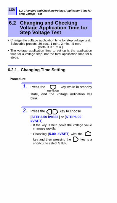
6.2 Changing and Checking Voltage Application Time for Step Voltage Test
128
• Change the voltage application time for step voltage test.Selectable presets: 30 sec., 1 min., 2 min. , 5 min.
(Default is 1 min.)• The voltage application time to set up is the application
time for a voltage step, not the total application time for 5steps.
6.2.1 Changing Time Setting
Procedure
1. Press the key while in standby
state, and the voltage indication willblink.
2. Press the key to choose
[STEP2.50 kVSET] or [STEP5.00 kVSET]. • If the key is held down the voltage value
changes rapidly.
• Choosing [5.00 kVSET] with the
key and then pressing the key is ashortcut to select STEP.
6.2 Changing and Checking Voltage Application Time for Step Voltage Test

6.2 Changing and Checking Voltage Application Time forStep Voltage Test
1
2
3
4
5
6
7
8
9
10
11
付録
索引
129
3. Press the key.
The voltage indication changes fromblinking to continuously lit, and theinstrument enters the step voltage testmode.
4. Press the key.
STEP and the time will blink.
5. Set the time using the key.
STEP is lighting.
Interval for 1 step
STEP is blinking.

6.2 Changing and Checking Voltage Application Time for Step Voltage Test
130
6. Press the key.
The time changes from blinking to con-tinuously lit.Setting of the time has been completed.
• The time can be set up on a PC using the data analysis software for 3455.
• The data analysis software for 3455 must be installed on the PC.
Details See 6.4 "Communicating with PC" (page 136).
6.2.2 Checking Time Setting
Procedure
1. Press the key while in standby
state, and the voltage indication willblink.
2. Choose a step voltage test mode ([STEP2.50 kVSET] or [STEP5.00
kVSET]) and press the key.The time for one step appears.
The time can also be set up on a PC
Interval for 1 step

6.3 Entering Temperature and Humidity Measured withExternal Thermometer and Hygrometer
1
2
3
4
5
6
7
8
9
10
11
付録
索引
131
Enter temperature and humidity measured with externalthermometer and hygrometer instead of the temperaturemeasuring function of the instrument.
• Disconnect the temperature sensor before entering the data.• After entering temperature and humidity, record them
using the memory function.• Details of memory functionDetails of memory function
See 5 "Recording Measurement Data (Memory Function)" (page 105).
• Input range: Temperature -10.0 to 70.0°C Humidity 0.0 to 99.9% RH
6.3 Entering Temperature and Humidity Measured with External Thermometer and Hygrometer
Operation Flow
Enter temperature/humidity.See "Entering Temperature and Humidity"
(page 132).
Save temperature/humidity data.See "Saving Temperature and Humidity
Data" (page 134).

6.3 Entering Temperature and Humidity Measured with External Thermometer and Hygrometer
132
6.3.1 Entering and Saving
Procedure
1. Press the key in standby state.
The temperature will blink.
2. Enter temperature using the
keys.
keys: Move the cursor.
keys: Raise and lower.
3. Press the key.
The humidity will blink.
When [TC] is on, the instrument returns tothe standby state without indicating humid-ity.
Entering Temperature and Humidity

6.3 Entering Temperature and Humidity Measured withExternal Thermometer and Hygrometer
1
2
3
4
5
6
7
8
9
10
11
付録
索引
133
4. Enter humidity using the
keys.
keys: Move the cursor.
keys: Raise and lower.
5. Press the key.
The instrument holds the entered tem-perature and humidity values.
• Even if humidity is held, when thetemperature sensor is connected, thehumidity is not displayed
• When resistance and current values arestill in memory or when the instrument isin the step voltage test mode, thetemperature and humidity indications areturned off after being entered and the timelights up.
• If the key is pressed when thetemperature and humidity indications areblinking, the instrument returns to thestandby state before they are entered.

6.3 Entering Temperature and Humidity Measured with External Thermometer and Hygrometer
134
Save the temperature and humidity data in the memory.
Procedure
6. Press the key.
7. Press the keys to
choose a data No.
8. Press the key.[MEMO No.] will blink and the data isrecorded.
Saving Temperature and Humidity Data
When only temperature and humidity arestored in the memory, they are recorded asstandard measurement data. Resistance,voltage and other data are recorded as - - -.
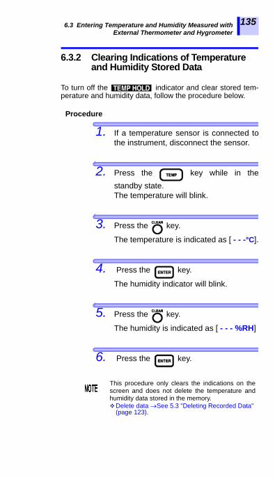
6.3 Entering Temperature and Humidity Measured withExternal Thermometer and Hygrometer
1
2
3
4
5
6
7
8
9
10
11
付録
索引
135
6.3.2 Clearing Indications of Temperature and Humidity Stored Data
To turn off the indicator and clear stored tem-perature and humidity data, follow the procedure below.
Procedure
1. If a temperature sensor is connected tothe instrument, disconnect the sensor.
2. Press the key while in thestandby state.The temperature will blink.
3. Press the key.
The temperature is indicated as [ - - -°C].
4. Press the key.
The humidity indicator will blink.
5. Press the key.
The humidity is indicated as [ - - - %RH]
6. Press the key.
This procedure only clears the indications on thescreen and does not delete the temperature andhumidity data stored in the memory.Delete data See 5.3 "Deleting Recorded Data"
(page 123).

6.4 Communicating with PC136
Data saved in the memory may be downloaded to a PC andthe instrument settings may be changed using a PC. • The data analysis software for 3455 (PC software) must
be installed on the PC. • Insulation resistance measurement, leakage current mea-
surement, or voltage measurement cannot be performedwhile the instrument is communicating with a PC.
• Transmits memory data to a PC from the instru-ment.
• Displays received data and logging records,and makes graphs of step voltage test data.
• Creates/prints out reports.• Edits the settings of the instrument on a PC. • Saves the data (CSV format)• Copies and pastes the graph• Saves the report in RTF format (non-
Windows8/10-compliant)
• Date and time• PI Interval • Voltage application time for step voltage test
6.4 Communicating with PC
What is it used for?Used to make a table or graph of the data stored in the memory or create a report.
Recommended System Requirements
OS Windows XP/Vista (32bit)Windows 7/8/10 (32bit/64bit)CPU : Pentium III, 500 MHz or fasterDisplay : 1024×768 resolution monitor,
32-bit color recommendedMemory : 128 MB of memory or more
HDD space Min. 30 MB free disk spaceInterface USB Ver2.0 (full speed)
Connectable to one IR3455 unit.
Functions of Data Analysis Softwarefor 3455
Settings Editable on PC

6.4 Communicating with PC
1
2
3
4
5
6
7
8
9
10
11
付録
索引
137
6.4.1 Installing Data Analysis Software for 3455
Before connecting the instrument to a PC for the first time,be sure to install the data analysis software for 3455 on thePC.
Procedure
1. Insert the CD into the CD-ROM drive.
2. Run the [X:/English/Data_Analysis_Software_for_3455Eng.exe]([X] represents the letter of the CD-ROMdrive, and may differ from computer tocomputer.)
3. Install the software by following the on-screen instructions.Refer to the user’s manual which is included in CD.
"Data Analysis Software for 3455" can bedowloaded from the HIOKI website URL http://www.hioki.com/

6.4 Communicating with PC138
6.4.2 Installing Driver
Installation procedure
1. Log in as "administrator" or as othersuch administrative authority.
2. Before installing, close all applicationscurrently running on the computer.
3. Execute the [driverSetup_English.msi]file inside the [/USB Driver] on theCD, and follow the instructions asshown on the screen to start the installa-tion.A warning message will be displayedbecause it would not qualify for the "Cer-tified for Windows" logos, but ignore itand continue the installation.
4. After installation is completed, the instru-ment will automatically be recognized bythe computer when connected with aUSB cable. If a search wizard screen fornew hardware is displayed, select [No,not this time] to confirm WindowsUpdate connection and select [Installthe software automatially].Even when connecting instruments ofdifferent serial numbers, you may benotified that a new device has beendetected. Follow the instructions on thescreen and install the device driver.

6.4 Communicating with PC
1
2
3
4
5
6
7
8
9
10
11
付録
索引
139
6.4.3 Downloading Data to Save to PC/ Setting up Instrument on PC
Procedure
1. Move the shutter to reveal the USB ter-minal.
2. Connect the USB Cable to the USB ter-minal.
3. Click the [Start] button and choose[Programs ] - [HIOKI ] - [3455 ] - [DataAnalysis Software for 3455 English].Operation See the help function or the user’s
manual of the data analysis software for 3455.
Use a 2-m or shorter USB cable to avoid noise.Do not connect to the instrument if test leadsare still connected.
Move the shutter.
USB terminal

6.4 Communicating with PC140
• To open the user's manual, click [Start] and then select [Programs] - [HIOKI] - [3455] - [Data Analysis Software For 3455 User's Manual].
• One IR3455 unit is connected to one PC.• Do not disconnect the USB Cable during
data transmission, to avoid transmissionerrors.
About the "Data Analysis Software for3455 User's Manual"
• The user's manual is stored in the[English] folder on the supplied CD.
• To view the user's manual, PDF viewersuch as Adobe Reader must be installedon your computer.

7.1 General Specifications
1
2
3
4
5
6
7
8
9
10
11
付録
索引
141
Specifications 77.1 General SpecificationsOperatingtemperature and humidity
-10°C to 40°C (14°F to 104°F), less than80% RH (no condensation)40°C to 50°C (104°F to 122°F), at 50°Cand below relative with linear decreaseup to 50% RH(Battery pack charge: 0°C to 40°C, lessthan 80% RH)
Storagetemperature and humidity
-10°C to 50°C (14°F to 122°F), less than90% RH (no condensation)Battery pack: -20°C to 30°C, less than80% RH (no condensation)
Guaranteedaccuracy period
1 year
Operatingenvironment
Indoors, Pollution degree 2,Up to 2000 m (6562 ft.) ASL
Measuring method
DC voltage application (insulation resis-tance) and mean-value rectification (voltage)
A-D conversion Double integral
Display LCD with backlight displaying up to acount of 999
Overflowindication >, OF
Underflowindication <, -OF
Display update rate
• Insulation resistance/leakage current:Once/sec. (0.25 times/sec. if averagingfunction used)
• Output voltage monitor: Twice/sec.• Voltage measurement: Fourth/sec.• Temperature measurement:Once/sec.• Bar graph: Twice/sec.

7.1 General Specifications142
Terminals (1) Insulation resistance/voltage mea-
surement: +, -, GUARD (GUARD ter-minal is used for insulation resistance/leakage current measurement only.)(2) Other: Temperature sensor, USB, and AC adapter
(1) and (2) are mutually exclusive.Power supply • AA alkaline battery (LR6) × 6, Rated
supply voltage 1.5 VDC × 6• 9459 BATTERY PACK
Rated supply voltage 7.2 VDC (Rechargeable, NiMH)
• 9753 AC ADAPTERRated supply voltage 100 to 240 VAC(Voltage fluctuations of ±10% are takeninto account.), Rated supply frequency50/60 Hz, Output rating 12 VDC, 3.33 A
Maximum rated power
15 VA (when AC adapter is used), 6 VA (when battery or battery pack is used)
Life of back up battery Approx. 10 years (reference data at 23°C)
Continuous operating time
Alkaline battery: Approx. 5 hours9459 BATTERY PACK: Approx. 9 hours(Conditions: Generating 5 kV, Openbetween + & - terminals, backlight off,and reference data at 23°C)
Maximum input voltage 750 VAC, 1000 VDC
Maximum input frequency 70 Hz
Maximum rated voltage to earth
Measurement category III 1000 V, Measurement category IV 600 V,(anticipated transient overvoltage 8000 V)
Overload protection
1000 VAC, 1200 VDC 1 min.Between + & - terminals
Dustproof and waterproof
IP40 (EN60529)When the USB port is covered by theshutter
Maximum capacitance load
4 F
Dimensions Approx. 260W × 251H × 120D mm(Approx. 10.2"W×9.9"H×4.7"D)(Not including handle and protrusions)

7.1 General Specifications
1
2
3
4
5
6
7
8
9
10
11
付録
索引
143
Mass Approx. 2.8 kg (Approx. 98.8 oz.)
(Including the accessories; test leads, alli-gator clips and alkaline battery)Standards Safety EN61010EMC EN61326
Product war-ranty period 3 years
Accessories • 9750-01 TEST LEAD(Red, Approx. 3 m) .............................. 1
• 9750-02 TEST LEAD(Black, Approx. 3 m)............................ 1
• 9750-03 TEST LEAD(Blue, Approx. 3 m, for GUARD) ........ 1
• 9751-01 ALLIGATOR CLIP (Red) ....... 1• 9751-02 ALLIGATOR CLIP (Black) ..... 1• 9751-03 ALLIGATOR CLIP
(Blue, for GUARD).................................. 1• Instruction Manual ............................... 1• AA alkaline battery (LR6) .................... 6• USB Cable .......................................... 1• CD (Data Analysis Software for 3455)....1
Options • 9631-01 TEMPERATURE SENSOR(Thermistor, Molded type, Approx. 1 m)
• 9631-05 TEMPERATURE SENSOR(Thermistor, Molded type, Approx. 5 cm)
• 9750-11 TEST LEAD (Red, Approx. 10 m)• 9750-12 TEST LEAD (Black, Approx. 10 m)• 9750-13 TEST LEAD (Blue, Approx. 10 m,
for GUARD)• 9459 BATTERY PACK• 9753 AC ADAPTER
Interface • USB ver. 2.0 (full speed)• Used for communications using PC
application software (Data AnalysisSoftware for 3455)
PC application software
• Transmits data in memory from theinstrument to PC.
• Edits the instrument settings on PC.• Features report function.
Specifications of Model 9750 and 9751See 7.3 "9750-01/-02/-03/-11/-12/-13 and 9751-01/-02/-03 ALLI-GATOR CLIPs Specifications" (page 152).
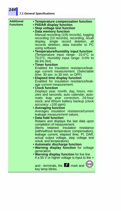
7.1 General Specifications144
Additional • Temperature compensation function
Functions • PI/DAR display function• Step voltage test function• Data memory function
Manual recording (100 records), loggingrecording (10 records), recording, recalldisplay, single record deletion, allrecords deletion, data transfer to PCusing software
• Temperature/humidity input function(Temperature input range: -10.0°C to70.0°C, Humidity input range: 0.0% to99.9% RH)
• Timer functionEnabled for insulation resistance/leak-age current measurement. (Selectabletime: 30 sec. to 30 min. or OFF)
• Elapsed time display functionEnabled for insulation resistance/leak-age current measurement.
• Clock functionDisplays year, month, day, hours, min-utes and seconds; auto calendar; auto-matic leap year correction; 24-hourclock; and lithium battery backup (clockaccuracy: ±100 ppm)
• Averaging functionAverages insulation resistance/currentleakage measurement values.
• Data hold functionRetains and displays the last data uponcompletion of measurement.(Items retained: Insulation resistance(with/without temperature compensation),leakage current, elapsed time, PI, DAR,actual output voltage, step voltage testresult, and temperature)
• Automatic discharge function• Warning display function for voltage
generation• Warning display function for live line
If a 50 V or higher voltage is input to the +
and - terminals, the mark and key lamp blinks.
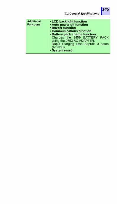
7.1 General Specifications
1
2
3
4
5
6
7
8
9
10
11
付録
索引
145
Additional Functions
• LCD backlight function• Auto power off function• Buzzer function• Communications function• Battery pack charge function
Charges the 9459 BATTERY PACKusing the 9753 AC ADAPTER.Rapid charging time: Approx. 3 hours(at 23°C)
• System reset

7.2 Measurement Specifications146
Values measured: Insulation resistance, leakage current,voltage, and temperature
7.2.1 Insulation Resistance Measurement
7.2 Measurement Specifications
Measurement test voltage
Selectable range: 250 V DC to 5.00 kVDCSetting method:• Choose from test voltage presets (250 V,
500 V, 1 kV, 2.5 kV, 5 kV)• Fine adjustment (between 250 V and 1
kV with a resolution of 25 V or between 1kV and 5 kV with a resolution of 100 V.)
Output voltage accuracy
• -0% and +10% of setting• Applies when the instrument measures
a resistance equal to or higher than theresult of division of test voltage (setvalue) by rated measuring current.
Short-circuit current
2 mA or less
Output voltage monitor function
Display range: 0 V to 999 V, 0.98 kV to5.50 kVMonitored value accuracy: ±5% rdg.±5 dgt.(Actual output voltage is within the toleranceof the output voltage accuracy given above.)
Measuring range
Resistance obtained by dividing the valueof the range from 0.00 M to the test volt-age (set value) by 0.5 nA (Measuringrange varies according to test voltage.)
*Rated measuring current:Electric current that can be generated with the set test voltage is maintained.
Test voltage(setting)
Rated measuring current*
(Tolerance: -0%,+10%)
250 V to 1.00 kV 1 mA1.10 kV to 2.50 kV 0. 5 mA2.60 kV to 5.00 kV 0.25 mA
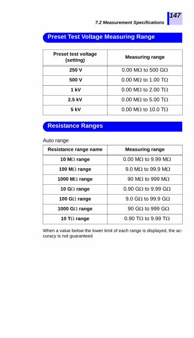
7.2 Measurement Specifications
1
2
3
4
5
6
7
8
9
10
11
付録
索引
147
Auto range
When a value below the lower limit of each range is displayed, the ac-curacy is not guaranteed
Preset Test Voltage Measuring Range
Preset test voltage (setting) Measuring range
250 V 0.00 M to 500 G
500 V 0.00 M to 1.00 T
1 kV 0.00 M to 2.00 T
2.5 kV 0.00 M to 5.00 T
5 kV 0.00 M to 10.0 T
Resistance range name Measuring range
10 M range 0.00 M to 9.99 M
100 M range 9.0 M to 99.9 M
1000 M range 90 M to 999 M
10 G range 0.90 G to 9.99 G
100 G range 9.0 G to 99.9 G
1000 G range 90 G to 999 G
10 T range 0.90 T to 9.99 T
Resistance Ranges

7.2 Measurement Specifications148
Temperature and humidity range for guaranteed accuracy:0°C to 28°C, less than 80% RH (no condensation)
Measuring range Measurement accuracy
Equal to or less than the resistance obtained by dividing the test voltage (set value) by 100 nA.
±5%rdg.±5dgt.
Greater than the resistance calculated by dividing the test voltage (setting value) by 100 nA, less than or equal to the resistance calculated by dividing the test voltage (setting value) by 1 nA, or less than or equal to 500 G
±20%rdg.±5dgt.
Greater than the resistance calculated by dividing the test voltage (setting value) by 1 nA, or within the range of 501 G to 9.99 T
±30%rdg.±50dgt.
Measurement Accuracy
Test voltage (set value)
Insu
latio
n re
sist
ance
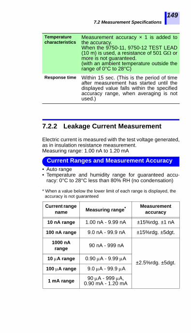
7.2 Measurement Specifications
1
2
3
4
5
6
7
8
9
10
11
付録
索引
149
7.2.2 Leakage Current Measurement
Electric current is measured with the test voltage generated,as in insulation resistance measurement.Measuring range: 1.00 nA to 1.20 mA
• Auto range• Temperature and humidity range for guaranteed accu-
racy: 0°C to 28°C less than 80% RH (no condensation)
Temperature characteristics
Measurement accuracy × 1 is added tothe accuracy.When the 9750-11, 9750-12 TEST LEAD(10 m) is used, a resistance of 501 G ormore is not guaranteed.(with an ambient temperature outside therange of 0°C to 28°C)
Response time Within 15 sec. (This is the period of timeafter measurement has started until thedisplayed value falls within the specifiedaccuracy range, when averaging is notused.)
* When a value below the lower limit of each range is displayed, the accuracy is not guaranteed
Current range name Measuring range* Measurement
accuracy
10 nA range 1.00 nA - 9.99 nA ±15%rdg. ±1 nA
100 nA range 9.0 nA - 99.9 nA ±15%rdg. ±5dgt.
1000 nA range 90 nA - 999 nA
±2.5%rdg. ±5dgt.10 A range 0.90 A - 9.99 A
100 A range 9.0 A - 99.9 A
1 mA range 90 A - 999 A, 0.90 mA - 1.20 mA
Current Ranges and Measurement Accuracy
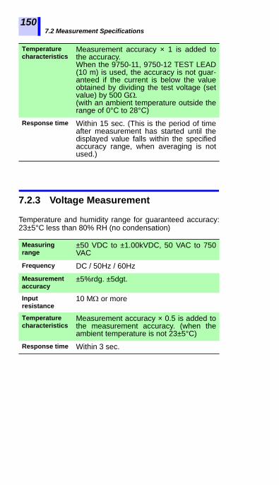
7.2 Measurement Specifications150
Temperature Measurement accuracy × 1 is added to
7.2.3 Voltage Measurement
Temperature and humidity range for guaranteed accuracy:23±5°C less than 80% RH (no condensation)
characteristics the accuracy.When the 9750-11, 9750-12 TEST LEAD(10 m) is used, the accuracy is not guar-anteed if the current is below the valueobtained by dividing the test voltage (setvalue) by 500 G.(with an ambient temperature outside therange of 0°C to 28°C)
Response time Within 15 sec. (This is the period of timeafter measurement has started until thedisplayed value falls within the specifiedaccuracy range, when averaging is notused.)
Measuring range
±50 VDC to ±1.00kVDC, 50 VAC to 750VAC
Frequency DC / 50Hz / 60HzMeasurement accuracy
±5%rdg. ±5dgt.
Input resistance
10 M or more
Temperature characteristics
Measurement accuracy × 0.5 is added tothe measurement accuracy. (when theambient temperature is not 23±5°C)
Response time Within 3 sec.
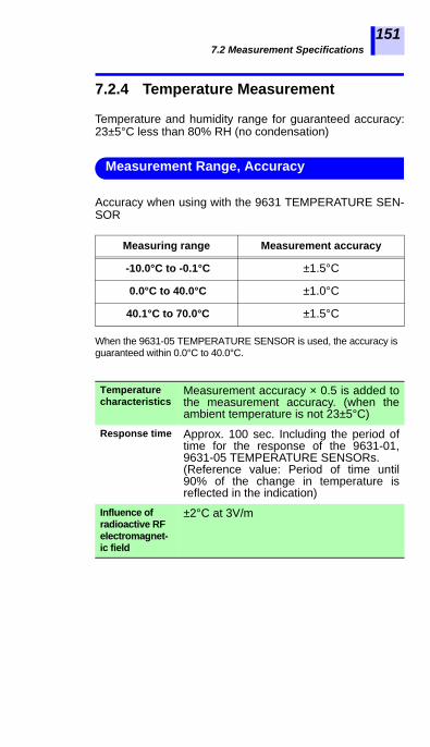
7.2 Measurement Specifications
1
2
3
4
5
6
7
8
9
10
11
付録
索引
151
7.2.4 Temperature Measurement
Temperature and humidity range for guaranteed accuracy:23±5°C less than 80% RH (no condensation)
Accuracy when using with the 9631 TEMPERATURE SEN-SOR
When the 9631-05 TEMPERATURE SENSOR is used, the accuracy is guaranteed within 0.0°C to 40.0°C.
Measuring range Measurement accuracy
-10.0°C to -0.1°C ±1.5°C
0.0°C to 40.0°C ±1.0°C
40.1°C to 70.0°C ±1.5°C
Measurement Range, Accuracy
Temperature characteristics
Measurement accuracy × 0.5 is added tothe measurement accuracy. (when theambient temperature is not 23±5°C)
Response time Approx. 100 sec. Including the period oftime for the response of the 9631-01,9631-05 TEMPERATURE SENSORs.(Reference value: Period of time until90% of the change in temperature isreflected in the indication)
Influence of radioactive RF electromagnet-ic field
±2°C at 3V/m

7.3 9750-01/-02/-03/-11/-12/-13 and 9751-01/-02/-03 ALLI-GATOR CLIPs Specifications
152
9750-01/-02/-03/-11/-12/-13 TEST LEADs and 9751-01/-02/-03 ALLIGATOR CLIPs are exclusively for use withIR3455 and IR3455-30.
7.3 9750-01/-02/-03/-11/-12/-13 and 9751-01/-02/-03 ALLIGA-TOR CLIPs Specifications
Operatingtemperature and humidity
-10°C to 50°C (14°F to 122°F), less than80% RH (no condensation)
Operatingenvironment
Indoors, Pollution degree 2, Up to 2000 m (6562 ft.) ASL
Storagetemperature and humidity
-10°C to 50°C (14°F to 122°F), less than90% RH (no condensation)
Maximum rated voltage to earth
5000 VDC/2 mA (insulation resistance measurement)
1000 VACMeasurement category III
600 VACMeasurement category IV
Anticipated transient overvoltage 8000 VRated voltage 1000 VAC, 5000 VDCRated current 10 AApplicable Standards
Safety EN61010
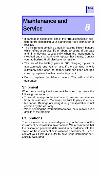
1
2
3
4
5
6
7
8
9
10
11
付録
索引
153
• If damage is suspected, check the "Troubleshooting" sec-tion before contacting your authorized Hioki distributor orreseller.
• The instrument contains a built-in backup lithium battery,which offers a service life of about 10 years. If the dateand time deviate substantially when the instrument isswitched on, it is the time to replace that battery. Contactyour authorized Hioki distributor or reseller.
• The life of the battery pack is 500 charging cycles orapproximately one year of use. If the operating time isextremely short after the battery pack has been chargedcorrectly, replace it with a new battery pack.
• Do not replace the lithium battery. This will void theguarantee.
ShipmentWhen transporting the instrument be sure to observe thefollowing precautions:• To avoid damage to the instrument, remove the batteries
from the instrument. Moreover, be sure to pack in a dou-ble carton. Damage occurring during transportation is notcovered by the warranty.
• When sending the instrument for repair, be sure to includedetails of the problem.
CalibrationsThe calibration period varies depending on the status of theinstrument or installation environment. We recommend thatthe calibration period be determined in accordance with thestatus of the instrument or installation environment. Pleasecontact your Hioki distributor to have your instrument peri-odically calibrated.
Maintenance and Service 8

8.1 Troubleshooting
154
If the instrument is not working correctly, check the trouble-shooting table below first before contacting authorized Hiokidistributor or reseller.
8.1 Troubleshooting
Problem Check Item Action ReferenceSection
Power is not turned on
•Is the battery installed?
•Is battery power low?
Install new battery
2.1.1 (P.36)
Is the battery polarity cor-rect?
Check the polarity
2.1.1 (P.36)
Is the battery pack charged?
Charge the battery pack.
2.1.4 (P.47)
Is the battery selector switch in the correct position?
Check the position of the battery selec-tor switch.
2.1.1 (P.36)
2.1.2 (P.39)
Battery pack is not
charged.
Is the power plug of the AC adapter inserted fully?
Is the power plug of the AC adapter inserted fully?
2.1.3 (P.45)
Is the battery pack installed?
Install the bat-tery pack.
2.1.2 (P.39)
Resistance measurement
value is incorrect.
Is the test lead damaged?
Replace the test lead. -
Is the test lead inserted fully?
Insert the test lead fully. 2.4 (P.56)
Are the test leads con-nected to the correct termi-nals?
Check the ter-minals. 2.4 (P.56)

8.1 Troubleshooting
1
2
3
4
5
6
7
8
9
10
11
付録
索引
155
If the cause is unknown, try resetting the system.See 8.4 "Performing System Reset" (page 158).
Monitored voltage during
resistance measurement
is low.
Is the resis-tance small?
The output voltage is low-ered for mea-surement of low resistance values.
Appendix 1 (P.163)
Temperature is not
measured.
Is the sensor inserted fully?
Insert the sen-sor fully. 2.5 (P.58)
Resistance is not measured in temperature compensation
mode.
Have you mea-sured tempera-ture first?
Measure tem-perature before resis-tance.
4.3 (P.93)
The instrument
cannot communicate with the PC.
Is the USB cable connec-tor inserted fully?
Insert the USB cable connec-tor fully.
6.4 (P.136)
Power fails upon
measuring insulation resistance.
Is the battery power low?
Replace with new battery.
2.1.1 (P.36)
Is the battery pack charged?
Charge the battery pack.
2.1.4 (P.47)
Is the GUARD terminal short-circuited with the test lead connected to the + terminal?
Check the connection to the test lead clips.
3.2.1Proce-dure 3. (P.65)
Problem Check Item Action ReferenceSection

8.2 Cleaning
156
To clean the instrument, wipe it gently with a soft clothmoistened with water or mild detergent.Wipe the instrument with a dry cloth for finishing.
8.2 Cleaning
Wipe the LCD gently with a soft, dry cloth.
8.3 Error Display
Error display Details Action
rEC Err Data stored in the memory is corrupted or missing.
Delete the data.
rEC FullMemory data are stored under all the data numbers and there is no vacant No.
Delete or replace data.
n0 AdJ Internal memory error has occurred.
This requires repair.
LObAt AA batteries or battery pack is low.
Replace the batteries or charge the battery pack.
Err00 Internal ROM error has occurred. This
requires repair.Err01 Internal memory error has
occurred.
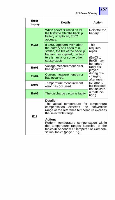
8.3 Error Display
1
2
3
4
5
6
7
8
9
10
11
付録
索引
157
Err02
When power is turned on for the first time after the backup battery is replaced, Err02 appears.
Reinstall the battery.
If Err02 appears even after the battery has been rein-stalled, the life of the backup battery has expired, the bat-tery is faulty, or some other cause exists.
This requires repair.
(Err03 to Err05 may be tempo-rarily dis-played during dis-charging after mea-surement, but this does not indicate a malfunc-tion.)
Err03 Voltage measurement error has occurred.
Err04 Current measurement error has occurred.
Err05 Temperature measurement error has occurred.
Err06 The discharge circuit is faulty.
E11
Details:The actual temperature for temperaturecompensation exceeds the convertiblerange or the reference temperature exceedsthe selectable range..
Action:Perform temperature compensation withinthe temperature ranges specified in thetables in Appendix 4 "Temperature Compen-sation Table" (page 165).
Error display Details Action

8.4 Performing System Reset
158
System reset returns the settings of the instrument to theirdefaults (excluding date and time), but this will not clear thememory data.
Procedure
1. While holding down the key in
standby state, press the key.[rESEt] appears.
2. Press the key, and [rESEt] will
blink and the LCD returns to the standbyscreen. System reset is complete.
The table below shows the default settings.
8.4 Performing System Reset
Setting Items Settings
Resistance/current Resistance
Test voltage 250 V
Timer OFF
PI interval t1=1 min., t2=10 min.
Temperature compensation OFF
Table No. displayed first when temperature
compensation is selected.0
Reference temperature for temperature compensation
20°C for table No. 0 to 840°C for table No. 9
Step voltage test OFF
Duration of one step in step voltage test 1 min.
Logging recording interval 1 min.
Average OFF
Auto power off ON

8.5 Discarding the Instrument
1
2
3
4
5
6
7
8
9
10
11
付録
索引
159
When disposing of this instrument, remove the lithium bat-tery and dispose of battery and instrument in accordancewith local regulations.
8.5 Discarding the Instrument
• To avoid electric shock or malfunctionof the instrument, do not attempt to usethe instrument again by installing a newlithium battery.
• Keep batteries away from children toprevent accidental swallowing.
CALIFORNIA, USA ONLYPerchlorate Material - special handling may apply.See www.dtsc.ca.gov/hazardouswaste/perchlorate

8.5 Discarding the Instrument
160
Removal of Lithium Battery
Tools: Phillips screwdriver, hexagonal wrench,and tweezers
1. Turn off power to the instrument andremove the AA batteries and batterypack.See 2.1.1 "Installing or Replacing the Battery"
(page 36), and 2.1.2 "Installing the Battery Pack (Rechargeable nickel-hydrogen battery)" (page 39)
2. Remove the four set screws on the rear ofthe instrument and remove the lower cas-ing.
Set screw
Set screw

8.5 Discarding the Instrument
1
2
3
4
5
6
7
8
9
10
11
付録
索引
161
3. Remove the screw and pin holding thetwo printed circuit boards, and removethem.The PCB nearest the LCD should not beremoved.
Remove
Lithium Battery
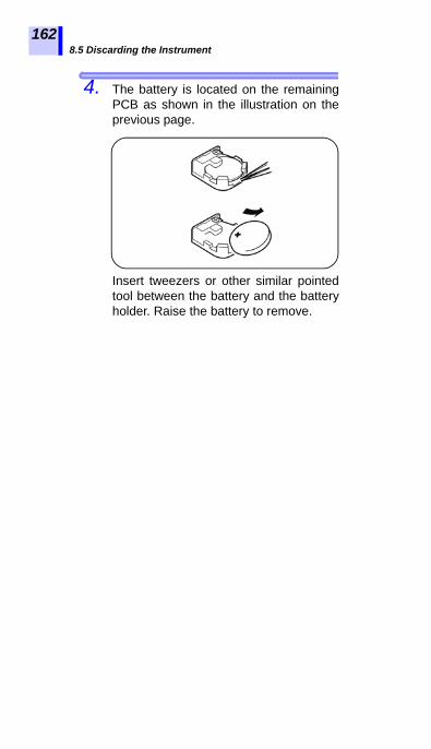
8.5 Discarding the Instrument
162
4. The battery is located on the remainingPCB as shown in the illustration on theprevious page.
Insert tweezers or other similar pointedtool between the battery and the batteryholder. Raise the battery to remove.

Appendix 1 Test Voltage Characteristic Graph
1
2
3
4
5
6
7
8
9
10
11
付録
索引
163
AppendixAppendix 1 Test Voltage
Characteristic Graph
Measurement resistance []
Out
put v
olta
ge [V
]
Measurement resistance []
Out
put v
olta
ge [V
]

Appendix 2 Example of Insulation Resistance Criteria
164
Primary criteria for insulation resistance of high-voltage cable(as a rough guide)
High-voltage power receiving facility code 2002
IEEE43-2000 Recommended Practice for Testing InsulationResistance of Rotating Machinery recommends the criteriaas shown in the table below for insulation resistance testingof a motor.
Appendix 2 Example of Insulation Resistance Criteria
Part of cable Measurement voltage [V]
Insulation resistance
[M]Judgment
Insulator 5,000
5,000 or more Non-defective
500 to below 5,000
Needs attention
below 500 Defective
Sheath 500 or 250 1 or more Non-defective
Appendix 3 Example of PI Criteria (Polarization Index)
Heat resistance class Recommended lowest PI
Class A 1.5 or more
Class B 2.0 or more
Class F 2.0 or more
Class H 2.0 or more

Appendix 4 Temperature Compensation Table
1
2
3
4
5
6
7
8
9
10
11
付録
索引
165
The temperature compensation function uses the tablesbelow.• Tables No.0 to 8 are based on Chinese standards.• Table No.9 is based on the US IEEE standards.
Table No.0
Source GB50150-91 Standard for hand-over test of electric equipment, electric equipment installation engineering (Chinese)
Reference DL/T596-1996 Power installation preventive mainte-nance code (Chinese)
Appendix 4 Temperature Compen-sation Table
Object under test Oil-impregnated power transformerSelectable reference temperature range
-10 to 70°C (default 20°C)
Convertible range of actual temperature used for measurement
-10.0 to 70.0°C
Compensation formula
Rtref : Resistance after compen-sation for reference tem-perature of tref°C
Rt : Resistance measured at the temperature of t°C
tref : Reference temperature [°C]t : Actual temperature used
for measurement [°C]
Rtref 1.5t tref– 10
Rt=

Appendix 4 Temperature Compensation Table
166
Table No.1
Source GB50150-91 Standard for hand-over test of electric equip-ment, electric equipment installation engineering (Chinese)
Object under test Motor stator winding: thermoplas-tic insulating material
Selectable reference temperature range
5 to 75°C, (default 20°C)
Convertible range of actual temperature used for measurement
5.0 to 70.0°C
Compensation formula
Converted to a resistance value atthe reference temperature usingthe formula below and result dis-played.
Rtref : Resistance after compen-sation for reference tem-perature of tref°C
Rt : Resistance measured at the temperature of t°C
tref : Reference temperature [°C]t : Actual temperature used
for measurement [°C]
Rtref 2t tref– 10
Rt=

Appendix 4 Temperature Compensation Table
1
2
3
4
5
6
7
8
9
10
11
付録
索引
167
Table No.2
Source GB50150-91 Standard for hand-over test of electric equip-ment, electric equipment installation engineering (Chinese)
Object under test Motor stator winding: Class B ther-mosetting insulating material
Selectable reference temperature range
5 to 100°C, (default 20°C)
Convertible range of actual temperature used for measurement
5.0 to 70.0°C
Compensation formula
Converted to a resistance value atthe reference temperature usingthe formula below and result dis-played.
Rtref : Resistance after compen-sation for reference tem-perature of tref°C
Rt : Resistance measured at the temperature of t°C
tref : Reference temperature [°C]t : Actual temperature used
for measurement [°C]
Rtref 1.6t tref– 10
Rt=

Appendix 4 Temperature Compensation Table
168
Table No.3 to 8
Object under test Power cable (Classified in one ofthe tables No.3 to 8 depending onmaterial and operating voltage.)
Selectable reference temperature range
Selectable range of each table isas follows. Set to 20°C by default.Table No.3: -5 to 40°CTable No.4: -5 to 36°CTable No.5: 1 to 40°CTable No.6: 0 to 40°CTable No.7: 0 to 40°CTable No.8: 0 to 40°C
Convertible range of actual temperature used for measurement
The selectable ranges are asshown above.
Compensation formula
• Converted to a resistance valueat the reference temperatureusing the formula below andresult displayed.
• Use the coefficients shown in the"Temperature Conversion Coeffi-cient for Power Cables" (page169).
Atref : Coefficient at the reference temperature of tref°C
At : Coefficient at the actual measurement temperature of t°C
Rtref : Resistance after compen-sation for reference tem-perature of tref°C
Rt : Resistance measured at the temperature of t°C
tref : Reference temperature [°C]t : Actual measurement tem-
perature [°C] (The decimals are rounded in compensa-tion mode.)
Rtref At Atref Rt=

Appendix 4 Temperature Compensation Table
1
2
3
4
5
6
7
8
9
10
11
付録
索引
169
Temperature Conversion Coefficient for Power Cables
Coefficient A
Temperatu
re[°C]
Oil filled insulated
cable
Polyvinyl chlorideinsulated cable Natural
rubber
Natural butadiene styrene
Butyl rubber
1 to 3 kV 6 kV
Table No.3
Table No.4
Table No.5
Table No.6
Table No.7
Table No.8
-5 0.08 0.016 - - - -
-4 0.09 0.019 - - - -
-3 0.10 0.024 - - - -
-2 0.11 0.029 - - - -
-1 0.13 0.032 - - - -
0 0.14 0.042 - 0.38 0.27 0.34
1 0.16 0.048 0.25 0.40 0.28 0.35
2 0.18 0.054 0.26 0.42 0.29 0.38
3 0.20 0.070 0.27 0.44 0.31 0.40
4 0.22 0.077 0.28 0.46 0.33 0.42
5 0.24 0.091 0.29 0.48 0.36 0.44
6 0.26 0.109 0.31 0.51 0.39 0.46
7 0.30 0.124 0.33 0.54 0.42 0.49
8 0.33 0.151 0.36 0.57 0.45 0.52
9 0.37 0.183 0.37 0.60 0.48 0.54
10 0.41 0.211 0.38 0.63 0.51 0.58
11 0.44 0.249 0.41 0.67 0.54 0.61
12 0.49 0.292 0.48 0.71 0.58 0.64
13 0.52 0.340 0.52 0.74 0.62 0.68
14 0.56 0.402 0.58 0.79 0.66 0.72
15 0.61 0.468 0.59 0.82 0.70 0.76
16 0.64 0.547 0.63 0.85 0.75 0.81
17 0.73 0.638 0.74 0.88 0.80 0.85
18 0.82 0.744 0.78 0.92 0.86 0.90

Appendix 4 Temperature Compensation Table
170
Temperature Conversion Coefficient for Power Cables
Source Electric wire and cable handbook (China) China Machine Press
19 0.91 0.857 0.85 0.96 0.93 0.96
20 1 1 1 1 1 1
21 1.09 1.17 1.11 1.06 1.11 1.07
22 1.18 1.34 1.20 1.13 1.23 1.14
23 1.26 1.57 1.40 1.20 1.36 1.22
24 1.33 1.81 1.80 1.27 1.51 1.30
25 1.44 2.08 1.90 1.35 1.68 1.38
26 1.55 2.43 2.05 1.44 1.87 1.45
27 1.68 2.79 2.40 1.54 2.08 1.55
28 1.76 3.22 2.70 1.65 2.31 1.65
29 1.92 3.71 3.80 1.77 2.57 1.77
30 2.09 4.27 4.10 1.90 2.86 1.89
31 2.25 4.92 4.45 2.03 3.18 2.00
32 2.42 5.60 5.20 2.17 3.53 2.15
33 2.60 6.45 5.80 2.32 3.91 2.32
34 2.79 7.42 7.60 2.47 4.33 2.50
35 2.95 8.45 8.28 2.65 4.79 2.69
36 3.12 9.70 8.50 2.85 5.29 2.90
37 3.37 - 9.66 3.10 5.83 3.13
38 3.58 - 11.60 3.35 6.44 3.38
39 4.06 - 14.50 3.63 7.18 3.65
40 4.53 - 16.00 3.95 8.23 3.94
Coefficient A
Temperatu
re[°C]
Oil filled insulated
cable
Polyvinyl chlorideinsulated cable Natural
rubber
Natural butadiene styrene
Butyl rubber
1 to 3 kV 6 kV
Table No.3
Table No.4
Table No.5
Table No.6
Table No.7
Table No.8

Appendix 4 Temperature Compensation Table
1
2
3
4
5
6
7
8
9
10
11
付録
索引
171
Table No.9
Source IEEE Std 43-2000 Recommended Practice for Testing Insu-lation Resistance of Rotating Machinery (U.S.A.)
Object under test Rotating machinerySelectable reference temperature range
20 to 60°C, (Default 40°C)
Convertible range of actual temperature used for measurement
20 to 60°C
Compensation formula
Converted to a resistance value atthe reference temperature usingthe formula below and result dis-played.
Rtref : Resistance after compen-sation for reference tem-perature of tref°C
Rt : Resistance measured at the temperature of t°C
tref : Reference temperature [°C]t : Actual temperature used
for measurement [°C]
Rtref 0.5tref t– 10
Rt=

Appendix 4 Temperature Compensation Table
172

1
2
3
4
5
6
7
8
9
10
11
付録
索引


EN
IR3455
HIGH VOLTAGE INSULATION TESTER
Instruction Manual
Oct. 2016 Edition 1IR3455A961-00 16-10H


![Plastic Film Capacitors - Panasonic · Insulation resistance (IR) Withstand voltage ±10 % (K), ±20 % (M) Category temp. range −40 ℃ to +110 ℃ Rated voltage [AC] 275 V Capacitance](https://img.pdfslide.tips/doc/110x75/5eaa86acb8948405283e9700/plastic-film-capacitors-panasonic-insulation-resistance-ir-withstand-voltage.jpg)