Embed Size (px)
Citation preview

Hydraulic Crawler Crane
Model : BMS1200HD
17-1, Higashigotanda 2-chome, Shinagawa-ku,Tokyo 141-8626 JAPAN
Note: This catalog may contain photographs of machines with specifications, attachments and optional equipment not certified for operation in your country. Please consult KOBELCO for those items you may require. Due to our policy of continual product improvements all designs and specifications are subject to change without advance notice.Copyright by KOBELCO CRANES CO., LTD. No part of this catalog may be reproduced in any manner without notice.
Tel: +81-3-5789-2130 Fax: +81-3-5789-3372URL: http://www.kobelco-cranes.com/
Bulletin No. BMS1200HD-SPEC-NR1
Inquiries To :
Max. Lifting Capacity: 120 t x 5 mMax. Crane Boom Length: 61.0 m
KOBELCO is the corporate mark used by Kobe Steel on a variety of productsand in the names of a number of Kobe Steel Group companies.
130301F Printed in Japan


2
BMS1200HDCONTENTS
3 SPECIFICATIONS
5 GENERAL DIMENSIONS
6 BOOM ARRANGEMENTS
7 WORKING RANGES
8 SUPPLEMENTAL DATA
9 LIFTING CAPACITIES
11 SUPPLEMENTAL DATA FOR CLAMSHELL
12 LIFTING CAPACITIES
13 SUPPLEMENTAL DATA FOR BUCKET
14 LIFTING CAPACITIES
15 SUPPLEMENTAL DATA FOR BARGE
17 TRANSPORTATION PLAN
16 LIFTING CAPACITIES
21 PARTS AND ATTACHMENTS

3
SPECIFICATIONS
Power Plant
Model: MTU 12V2000Type: 4 cycle, water-cooled, 12 cylinders in 90° V design, direct injection, turbo-charger, intercooler.Displacement: 23.880 litersRated power: 634 kW / 1,800 min-1
Max. Torque: 3,750 N·m / 1,500 min-1
Cooling System: Water-cooledStarter: 24 V- 9 kwRadiator: Corrugated type core, thermostatically controlledAir cleaner: Dry type with replaceable paper elementThrottle: Twist grip type hand throttle, electrically actuatedFuel filter: Heavy duty with spin off type cartridge.Batteries: Two 12 V x 160 Ah capacity batteries, series connectedFuel tank capacity: 900 liters
Hydraulic System
Main pumps: 4 variable displacement piston pumpsControl: Full-flow hydraulic control system for infinitely variable pressure to all winches, propel and swing. Controls respond instantly to the touch, delivering smooth function operation.Cooling: Oil-to-air heat exchanger (plate-fin type)Filtration: Full-flow and bypass type with replaceable elementMax. relief valve pressure:
Load hoist, boom hoist and propel system: 32 MpaSwing system: 28 MPaControl system: 5.4 MPa
Hydraulic Tank Capacity: 1,000 liters
Boom Hoisting System
Powered by a hydraulic motor through a planetary reducer.Brake: A spring-set, hydraulically released multiple-disc brake is mounted on the boom hoist motor and operated through a counter-balance valve.Drum Lock: External ratchet for locking drumDrum: Single drum, grooved for 20 mm dia. wire ropeLine Speed: Single line on first drum layer
Hoisting/Lowering: 48 to 2 m/minBoom hoisting/lowering: 20 mm x 190 mBoom guy line: 30 mmBoom backstops: Required for all boom length
Load Hoisting System
Front and rear drums for load hoist powered by two hydraulic variable plunger motors, driven through planetary reducers.Positive & Negative Brake: Forced-circulation oil-cooled wet-type multi-disc brake, each using positive and negative actuation.
The drums are manually locked by the control cable. Both positive and negative brake systems are available in lever neutral position.Drum Lock: External ratchet for locking drumDrums:
Front Drums: 864 mm P.C.D x 799 mm Lg., grooved for 36 mm wire rope. Rope capacity is 245 m working length and 460 m storage length.Rear Drum: 864 mm P.C.D x 799 mm grooved for 36 mm wire rope. Rope capacity is 175 m working length and 460 m storage length.
Diameter of wire ropeMain winch: 36 mm x 245 mAux. winch: 36 mm x 175 mThird winch: 30 mm x 210 m
Line Speed*:Hoisting/lowering: 110 to 3 m/min
Line Pull:Max. Line Pull* : 314 kN {32.0 tf}(Referential Performance)Rated Line Pull: 157 kN {16.0 tf}
*Single line on first drum layer
Swing System
Swing unit is powered by hydraulic motor driving spur gears through planetary reducers, the swing system provides 360° rotation.Swing parking brakes: A spring-set, hydraulically released multiple-disc brake is mounted on swing motor.Swing circle: Single-row ball bearing with an integral internally cut swing gear.Swing lock: Manually, four position lock for transportationSwing Speed: 2.1 min-1
Upper Structure
Torsion-free precision machined upper frame. All components are located clearly and service friendly. Engine will with low noise level.Counterweight: 32.5 ton
Cab & Control
Totally enclosed, full vision cab with safety glass, fully adjustable, high backed seat with a headrest and armrests, and intermittent wiper and window washer (skylight and front window).Cab fittings: Air conditioner, convenient compartment (for tool), cup holder, cigarette lighter, sun visor, roof blind, tinted glass, floor mat, footrest, and shoe tray

4
Lower Structure
Steel-welded carbody with axles. Crawler assemblies are designed with quick disconnect feature for individual removal as a unit from axles. Crawler belt tension is maintained by hydraulic jack force on the track-adjusting bearing block.Crawler drive: Independent hydraulic propel drive is built into each crawler side frame. Each drive consists of a hydraulic motor propelling a driving tumbler through a planetary gear box. Hydraulic motor and gear box are built into the crawler side frame within the shoe width.Crawler brakes: Spring-set, hydraulically released parking brakes are built into each propel drive.Steering mechanism: A hydraulic propel system provides both skid steering (driving one track only) and counter-rotating steering (driving each track in opposite directions).Track rollers: Sealed track rollers for maintenance-free operation.Shoe (flat): 1,070 mm wide each crawlerMax. gradeability: 30 %
Weight
Including upper and lower machine, 32.5 ton counterweight, basic boom, hook, and other accessories.Weight: 116 tonGround pressure: 79 kPa
Attachment
Boom & Jib:Welded lattice construction using tubular, high-tensile steel chords with pin connection between sections.
Boom length
Min. Length Max. Length
Crane Boom 18.3 m 61.0 m
Main Specifications (Model: BMS1200HD) Crane Boom Max. Lifting Capacity 120 t x 5.0 m Max. Length 61.0 m Main & Aux. Winch Max. Line Speed (1st layer) 110 m/min Rated Line Pull (Single line) 157 kN {16.0 tf}Wire Rope Diameter 36 mmWire Rope Length 245 m (Main), 175 m (Aux.)Brake Type (free fall) Wet-type multiple disc brake (Standard)Working Speed Swing Speed 2.1 min-1{rpm}Travel Speed 1.2/0.8 km/hPower Plant Model MTU 12V2000Engine Output 634 kW / 1,800 min-1
Fuel Tank 900 liters
Hydraulic System Main Pumps 4 variable displacementMax. Pressure 32 MPa {326 kgf/cm2}Hydraulic Tank Capacity 1,000 litersSelf-Removal Device
NAWeight Operating Weight 116 t *1
Ground Pressure 79 kPaCounterweight 32,500 kgTransport Weight 46,900 kg *2
Units are SI units. { } indicates conventional units.Line speeds in table are for light loads. Line speed varies with load.*1 Including upper and lower machine, 32.5 ton counterweight, basic boom, hook,
and other accessories.*2 Base machine with gantry, wire rope (front/rear/boom hoist), without crawler,
auxiliary platform and duct.

5
GENERAL DIMENSIONS
6,890
7,860
2,38
0 3,63
0
7,70
0
4,01
0
1,35
02,
280
6,650
4,680 1,400
18.3
to 6
1.0
m
6,32051
0
3,490
1,750
950
R5,500
1,07
0
5,00
0
(Unit: mm)
Limit of Hook Lifting
L L’Hook L
120 t hook 4.7 m
70 t hook 4.7 m
50 t hook 4.5 m
Hook L’
Ball hook 4.2 m
This catalog may contain photographs of machines with specifications, attachments and optional equipment.
6
BOOM ARRANGEMENTS
Crane Boom ArrangementsBoom length m (ft)
Boom arrangement
18.3 (60) B
A
A
A
A
A
B
B
B C
ABB C
C
B
T
B 3.0 T
B 3.0 3.0 T
B 3.0 6.1 T
B 3.0 3.0 6.1 T
ABB D
B 3.0 3.0 9.1 T
ACB D
B 3.0 6.1 9.1 T
ACB B D
B 3.0 3.0 6.1 9.1 T
AB B DD
B 3.0 3.0 9.19.1 T
AB DCC
B 3.0 6.1 9.16.1 T
ADC D
B 6.1 9.19.1 T
ACC D
B 6.16.1 9.1 T
AB DD
B 3.0 9.19.1 T
ADD
B 9.19.1 T
AC D
B 6.1 9.1 T
ACB C
B 3.0 6.1 6.1 T
ADB
B 3.0 9.1 T
ACC
B 6.1 6.1 T
AD
B 9.1 T
B 6.1 T
※
※
※
※
※
※
※
※
21.3 (70)
B
A
A
A
A
A
B
B
B C
ABB C
C
B
T
B 3.0 T
B 3.0 3.0 T
B 3.0 6.1 T
B 3.0 3.0 6.1 T
ABB D
B 3.0 3.0 9.1 T
ACB D
B 3.0 6.1 9.1 T
ACB B D
B 3.0 3.0 6.1 9.1 T
AB B DD
B 3.0 3.0 9.19.1 T
AB DCC
B 3.0 6.1 9.16.1 T
ADC D
B 6.1 9.19.1 T
ACC D
B 6.16.1 9.1 T
AB DD
B 3.0 9.19.1 T
ADD
B 9.19.1 T
AC D
B 6.1 9.1 T
ACB C
B 3.0 6.1 6.1 T
ADB
B 3.0 9.1 T
ACC
B 6.1 6.1 T
AD
B 9.1 T
B 6.1 T
※
※
※
※
※
※
※
※
24.4 (80)
B
A
A
A
A
A
B
B
B C
ABB C
C
B
T
B 3.0 T
B 3.0 3.0 T
B 3.0 6.1 T
B 3.0 3.0 6.1 T
ABB D
B 3.0 3.0 9.1 T
ACB D
B 3.0 6.1 9.1 T
ACB B D
B 3.0 3.0 6.1 9.1 T
AB B DD
B 3.0 3.0 9.19.1 T
AB DCC
B 3.0 6.1 9.16.1 T
ADC D
B 6.1 9.19.1 T
ACC D
B 6.16.1 9.1 T
AB DD
B 3.0 9.19.1 T
ADD
B 9.19.1 T
AC D
B 6.1 9.1 T
ACB C
B 3.0 6.1 6.1 T
ADB
B 3.0 9.1 T
ACC
B 6.1 6.1 T
AD
B 9.1 T
B 6.1 T
※
※
※
※
※
※
※
※
27.4 (90)
B
A
A
A
A
A
B
B
B C
ABB C
C
B
T
B 3.0 T
B 3.0 3.0 T
B 3.0 6.1 T
B 3.0 3.0 6.1 T
ABB D
B 3.0 3.0 9.1 T
ACB D
B 3.0 6.1 9.1 T
ACB B D
B 3.0 3.0 6.1 9.1 T
AB B DD
B 3.0 3.0 9.19.1 T
AB DCC
B 3.0 6.1 9.16.1 T
ADC D
B 6.1 9.19.1 T
ACC D
B 6.16.1 9.1 T
AB DD
B 3.0 9.19.1 T
ADD
B 9.19.1 T
AC D
B 6.1 9.1 T
ACB C
B 3.0 6.1 6.1 T
ADB
B 3.0 9.1 T
ACC
B 6.1 6.1 T
AD
B 9.1 T
B 6.1 T
※
※
※
※
※
※
※
※
30.5 (100)
B
A
A
A
A
A
B
B
B C
ABB C
C
B
T
B 3.0 T
B 3.0 3.0 T
B 3.0 6.1 T
B 3.0 3.0 6.1 T
ABB D
B 3.0 3.0 9.1 T
ACB D
B 3.0 6.1 9.1 T
ACB B D
B 3.0 3.0 6.1 9.1 T
AB B DD
B 3.0 3.0 9.19.1 T
AB DCC
B 3.0 6.1 9.16.1 T
ADC D
B 6.1 9.19.1 T
ACC D
B 6.16.1 9.1 T
AB DD
B 3.0 9.19.1 T
ADD
B 9.19.1 T
AC D
B 6.1 9.1 T
ACB C
B 3.0 6.1 6.1 T
ADB
B 3.0 9.1 T
ACC
B 6.1 6.1 T
AD
B 9.1 T
B 6.1 T
※
※
※
※
※
※
※
※
33.5 (110)
B
A
A
A
A
A
B
B
B C
ABB C
C
B
T
B 3.0 T
B 3.0 3.0 T
B 3.0 6.1 T
B 3.0 3.0 6.1 T
ABB D
B 3.0 3.0 9.1 T
ACB D
B 3.0 6.1 9.1 T
ACB B D
B 3.0 3.0 6.1 9.1 T
AB B DD
B 3.0 3.0 9.19.1 T
AB DCC
B 3.0 6.1 9.16.1 T
ADC D
B 6.1 9.19.1 T
ACC D
B 6.16.1 9.1 T
AB DD
B 3.0 9.19.1 T
ADD
B 9.19.1 T
AC D
B 6.1 9.1 T
ACB C
B 3.0 6.1 6.1 T
ADB
B 3.0 9.1 T
ACC
B 6.1 6.1 T
AD
B 9.1 T
B 6.1 T
※
※
※
※
※
※
※
※
36.6 (120)
B
A
A
A
A
A
B
B
B C
ABB C
C
B
T
B 3.0 T
B 3.0 3.0 T
B 3.0 6.1 T
B 3.0 3.0 6.1 T
ABB D
B 3.0 3.0 9.1 T
ACB D
B 3.0 6.1 9.1 T
ACB B D
B 3.0 3.0 6.1 9.1 T
AB B DD
B 3.0 3.0 9.19.1 T
AB DCC
B 3.0 6.1 9.16.1 T
ADC D
B 6.1 9.19.1 T
ACC D
B 6.16.1 9.1 T
AB DD
B 3.0 9.19.1 T
ADD
B 9.19.1 T
AC D
B 6.1 9.1 T
ACB C
B 3.0 6.1 6.1 T
ADB
B 3.0 9.1 T
ACC
B 6.1 6.1 T
AD
B 9.1 T
B 6.1 T
※
※
※
※
※
※
※
※
39.6 (130)
B
A
A
A
A
A
B
B
B C
ABB C
C
B
T
B 3.0 T
B 3.0 3.0 T
B 3.0 6.1 T
B 3.0 3.0 6.1 T
ABB D
B 3.0 3.0 9.1 T
ACB D
B 3.0 6.1 9.1 T
ACB B D
B 3.0 3.0 6.1 9.1 T
AB B DD
B 3.0 3.0 9.19.1 T
AB DCC
B 3.0 6.1 9.16.1 T
ADC D
B 6.1 9.19.1 T
ACC D
B 6.16.1 9.1 T
AB DD
B 3.0 9.19.1 T
ADD
B 9.19.1 T
AC D
B 6.1 9.1 T
ACB C
B 3.0 6.1 6.1 T
ADB
B 3.0 9.1 T
ACC
B 6.1 6.1 T
AD
B 9.1 T
B 6.1 T
※
※
※
※
※
※
※
※
42.7 (140)
B
A
A
A
A
A
B
B
B C
ABB C
C
B
T
B 3.0 T
B 3.0 3.0 T
B 3.0 6.1 T
B 3.0 3.0 6.1 T
ABB D
B 3.0 3.0 9.1 T
ACB D
B 3.0 6.1 9.1 T
ACB B D
B 3.0 3.0 6.1 9.1 T
AB B DD
B 3.0 3.0 9.19.1 T
AB DCC
B 3.0 6.1 9.16.1 T
ADC D
B 6.1 9.19.1 T
ACC D
B 6.16.1 9.1 T
AB DD
B 3.0 9.19.1 T
ADD
B 9.19.1 T
AC D
B 6.1 9.1 T
ACB C
B 3.0 6.1 6.1 T
ADB
B 3.0 9.1 T
ACC
B 6.1 6.1 T
AD
B 9.1 T
B 6.1 T
※
※
※
※
※
※
※
※
Kind of boom insert
Symbol Length
6.1
9.1
3.0 3.0 m6.1
9.1
3.0
6.1 m6.1
9.1
3.0
9.1 m
※�mark shows the standard boom arrangement which enables each boom length of less than that boom length to be configured.
Boom length m (ft)
Boom arrangement
45.7 (150)
AB C DD
B 3.0 6.1 9.19.1 T
AB C DD
B 3.0
B
3.0 6.1 9.19.1 T
AB D DD
B 3.0
B
3.0 9.1 9.19.1 T
AC D DD
B 6.1 9.1 9.19.1 T
AB C DD
B 3.0
C
6.1 6.1 9.19.1 T
AB D DD
B 3.0
C
6.1 9.1 9.19.1 T
AD DD
B 9.1
D
9.1 9.19.1 T
AD DD
B 9.1
B
3.0
C
6.1
B
3.0 9.19.1 T
AD DD
B 9.1
D
9.1
B
3.0 9.19.1 T
AD DD
B 9.1
C
6.1
C
6.1 9.19.1 T
AD DD
B 9.1
C
6.1
C
6.1
B
3.0 9.19.1 T
AD DD
B 9.1
B
3.0
D
9.1
B
3.0 9.19.1 T
ACC DD
B 6.1 6.1 9.19.1 T
ADB DD
B 3.0 9.1 9.19.1 T
AD DD
B 9.1 9.19.1 T
※
※
※
※
※
※
48.8 (160)
AB C DD
B 3.0 6.1 9.19.1 T
AB C DD
B 3.0
B
3.0 6.1 9.19.1 T
AB D DD
B 3.0
B
3.0 9.1 9.19.1 T
AC D DD
B 6.1 9.1 9.19.1 T
AB C DD
B 3.0
C
6.1 6.1 9.19.1 T
AB D DD
B 3.0
C
6.1 9.1 9.19.1 T
AD DD
B 9.1
D
9.1 9.19.1 T
AD DD
B 9.1
B
3.0
C
6.1
B
3.0 9.19.1 T
AD DD
B 9.1
D
9.1
B
3.0 9.19.1 T
AD DD
B 9.1
C
6.1
C
6.1 9.19.1 T
AD DD
B 9.1
C
6.1
C
6.1
B
3.0 9.19.1 T
AD DD
B 9.1
B
3.0
D
9.1
B
3.0 9.19.1 T
ACC DD
B 6.1 6.1 9.19.1 T
ADB DD
B 3.0 9.1 9.19.1 T
AD DD
B 9.1 9.19.1 T
※
※
※
※
※
※
51.8 (170)
AB C DD
B 3.0 6.1 9.19.1 T
AB C DD
B 3.0
B
3.0 6.1 9.19.1 T
AB D DD
B 3.0
B
3.0 9.1 9.19.1 T
AC D DD
B 6.1 9.1 9.19.1 T
AB C DD
B 3.0
C
6.1 6.1 9.19.1 T
AB D DD
B 3.0
C
6.1 9.1 9.19.1 T
AD DD
B 9.1
D
9.1 9.19.1 T
AD DD
B 9.1
B
3.0
C
6.1
B
3.0 9.19.1 T
AD DD
B 9.1
D
9.1
B
3.0 9.19.1 T
AD DD
B 9.1
C
6.1
C
6.1 9.19.1 T
AD DD
B 9.1
C
6.1
C
6.1
B
3.0 9.19.1 T
AD DD
B 9.1
B
3.0
D
9.1
B
3.0 9.19.1 T
ACC DD
B 6.1 6.1 9.19.1 T
ADB DD
B 3.0 9.1 9.19.1 T
AD DD
B 9.1 9.19.1 T
※
※
※
※
※
※
54.9 (180)
AB C DD
B 3.0 6.1 9.19.1 T
AB C DD
B 3.0
B
3.0 6.1 9.19.1 T
AB D DD
B 3.0
B
3.0 9.1 9.19.1 T
AC D DD
B 6.1 9.1 9.19.1 T
AB C DD
B 3.0
C
6.1 6.1 9.19.1 T
AB D DD
B 3.0
C
6.1 9.1 9.19.1 T
AD DD
B 9.1
D
9.1 9.19.1 T
AD DD
B 9.1
B
3.0
C
6.1
B
3.0 9.19.1 T
AD DD
B 9.1
D
9.1
B
3.0 9.19.1 T
AD DD
B 9.1
C
6.1
C
6.1 9.19.1 T
AD DD
B 9.1
C
6.1
C
6.1
B
3.0 9.19.1 T
AD DD
B 9.1
B
3.0
D
9.1
B
3.0 9.19.1 T
ACC DD
B 6.1 6.1 9.19.1 T
ADB DD
B 3.0 9.1 9.19.1 T
AD DD
B 9.1 9.19.1 T
※
※
※
※
※
※
57.9 (190)
AB C DD
B 3.0 6.1 9.19.1 T
AB C DD
B 3.0
B
3.0 6.1 9.19.1 T
AB D DD
B 3.0
B
3.0 9.1 9.19.1 T
AC D DD
B 6.1 9.1 9.19.1 T
AB C DD
B 3.0
C
6.1 6.1 9.19.1 T
AB D DD
B 3.0
C
6.1 9.1 9.19.1 T
AD DD
B 9.1
D
9.1 9.19.1 T
AD DD
B 9.1
B
3.0
C
6.1
B
3.0 9.19.1 T
AD DD
B 9.1
D
9.1
B
3.0 9.19.1 T
AD DD
B 9.1
C
6.1
C
6.1 9.19.1 T
AD DD
B 9.1
C
6.1
C
6.1
B
3.0 9.19.1 T
AD DD
B 9.1
B
3.0
D
9.1
B
3.0 9.19.1 T
ACC DD
B 6.1 6.1 9.19.1 T
ADB DD
B 3.0 9.1 9.19.1 T
AD DD
B 9.1 9.19.1 T
※
※
※
※
※
※
61.0 (200)
AB C DD
B 3.0 6.1 9.19.1 T
AB C DD
B 3.0
B
3.0 6.1 9.19.1 T
AB D DD
B 3.0
B
3.0 9.1 9.19.1 T
AC D DD
B 6.1 9.1 9.19.1 T
AB C DD
B 3.0
C
6.1 6.1 9.19.1 T
AB D DD
B 3.0
C
6.1 9.1 9.19.1 T
AD DD
B 9.1
D
9.1 9.19.1 T
AD DD
B 9.1
B
3.0
C
6.1
B
3.0 9.19.1 T
AD DD
B 9.1
D
9.1
B
3.0 9.19.1 T
AD DD
B 9.1
C
6.1
C
6.1 9.19.1 T
AD DD
B 9.1
C
6.1
C
6.1
B
3.0 9.19.1 T
AD DD
B 9.1
B
3.0
D
9.1
B
3.0 9.19.1 T
ACC DD
B 6.1 6.1 9.19.1 T
ADB DD
B 3.0 9.1 9.19.1 T
AD DD
B 9.1 9.19.1 T
※
※
※
※
※
※

7
Crane Boom
WORKING RANGES

8
SUPPLEMENTAL DATA· Operating radius is the horizontal distance from centerline of rotation to a vertical line through the center of gravity of the load.
· Deduct weight of hook block (s), slings and all other load handling accessories from main boom ratings shown.
· Ratings shown are based on freely suspended loads and make no allowance for such factors as wind effect on lifted load, ground conditions, out-of-level, operating speeds or any other condition that could be detrimental to the safe operation of this equipment. The operator, therefore, has the responsibility to judge the existing conditions and reduce lifted loads and operating speeds accordingly.
· Ratings are for operation on a firm and level surface, up to 1% gradient.
· At radii and boom lengths where no ratings are shown on chart, operation is not intended nor approved.
· Boom inserts and guy lines must be arranged as shown in the "operator's manual".
· Boom hoist reeving is 12 part line.
· Gantry must be in raised position for all conditions.
· Boom backstops are required for all boom lengths.
· The boom should be erected over the front of the crawlers, not laterally.
· The minimum rated load is 1.5 (ton).
(Main boom)
· The total load that can be lifted is the value for weight of hook block, slings, and all other load handling accessories deducted from main boom ratings shown.
(Main boom with auxiliary sheave frame)
· The total load that can be lifted is the value for weight of main hook block, slings, and all other load handling accessories
deducted from main boom with auxiliary sheave ratings shown.
(Auxiliary sheave)
· The total load that can be lifted is the value for weight of hook block, slings, and all other load handling accessories deducted from auxiliary sheave ratings shown.
· Boom lengths for auxiliary sheave mounting are 18.3m to 54.9m.
Main hoist loads (Main Drum)No. of Parts of Line 1 2 3 4 5 6
Maximum Loads (kN) 157 294 441 588 735 883Maximum Loads (t) 16.0 30.0 45.0 60.0 75.0 90.0
No. of Parts of Line 7 8Maximum Loads (kN) 1,030 1,177Maximum Loads (t) 105.0 120.0
Auxiliary hoist loadsNo. of Parts of Line 1 2
Maximum Loads (kN) 157 294Maximum Loads (t) 16.0 30.0
Main hoist loads (Third Drum)No. of Parts of Line 1 2 3 4 5 6
Maximum Loads (kN) 132 265 397 530 662 794Maximum Loads (t) 13.5 27.0 40.5 54.0 67.5 81.0
No. of Parts of Line 7 8Maximum Loads (kN) 927 981Maximum Loads (t) 94.5 100.0
Weight of hook blockHook Block 120 t 70 t / 50 t 16 tWeight (t) 1.6 1.2 0.5
Operation of this equipment in excess of rated loads or disregard of instruction voids the warranty.

9
LIFTING CAPACITIES
Boom length
Working (m)radius (m)
18.3 21.3 24.4 27.4 30.5 33.5 36.6 39.6Boomlength(m) Working
radius (m)
5.0 120.0 5.05.5 100.0 5.56.0 91.6 91.5 91.4 6.5m/84.2 6.07.0 78.2 78.0 77.9 77.8 7.1m/76.5 7.6m/68.1 7.08.0 62.9 62.7 62.6 62.5 62.3 62.2 8.1m/60.9 8.6m/55.2 8.09.0 52.5 52.2 52.1 52.0 51.8 51.7 51.6 51.5 9.0
10.0 44.9 44.6 44.5 44.4 44.2 44.1 44.0 43.9 10.012.0 34.6 34.4 34.3 34.1 33.9 33.8 33.7 33.6 12.014.0 28.0 27.8 27.6 27.5 27.3 27.2 27.1 27.0 14.016.0 23.3 23.2 23.0 22.9 22.6 22.5 22.4 22.3 16.018.0 17.4m/19.0 19.8 19.5 19.5 19.2 19.1 19.0 18.9 18.020.0 16.2 17.0 16.9 16.6 16.5 16.3 16.2 20.022.0 15.0 14.8 14.5 14.4 14.2 14.1 22.024.0 22.7m/13.9 13.2 12.9 12.7 12.5 12.4 24.026.0 25.3m/12.0 11.5 11.3 11.1 11.0 26.028.0 10.3 10.2 10.0 9.9 28.030.0 9.2 9.0 8.9 30.032.0 30.6m/8.9 8.2 8.1 32.034.0 33.3m/7.5 7.4 34.036.0 35.9m/6.7 36.0
Reeves 8 7 7 6 6 5 5 4 Reeves
Boom length
Working (m)radius (m)
42.7 45.7 48.8 51.8 54.9 57.9 61.0Boomlength(m) Working
radius (m)
9.0 9.2m/50.2 9.7m/45.9 9.010.0 43.8 43.7 10.2m/42.2 10.8m/39.2 11.3m/36.4 11.8m/33.9 10.012.0 33.5 33.3 33.2 33.1 33.0 32.9 12.3m/29.0 12.014.0 26.8 26.7 26.6 26.5 26.4 26.2 26.0 14.016.0 22.2 22.0 21.9 21.8 21.7 21.5 21.3 16.018.0 18.7 18.6 18.5 18.4 18.2 18.1 17.8 18.020.0 16.1 15.9 15.8 15.7 15.6 15.4 15.2 20.022.0 14.0 13.8 13.7 13.6 13.5 13.3 13.1 22.024.0 12.3 12.1 12.0 11.9 11.8 11.6 11.4 24.026.0 10.9 10.7 10.6 10.5 10.4 10.2 10.0 26.028.0 9.8 9.6 9.4 9.3 9.2 9.0 8.8 28.030.0 8.8 8.6 8.4 8.3 8.2 8.0 7.8 30.032.0 7.9 7.7 7.6 7.5 7.3 7.1 6.9 32.034.0 7.2 7.0 6.8 6.7 6.6 6.4 6.2 34.036.0 6.5 6.3 6.2 6.1 5.9 5.7 5.5 36.038.0 6.0 5.8 5.6 5.5 5.3 5.1 4.9 38.040.0 38.5m/5.8 5.3 5.1 5.0 4.8 4.6 4.4 40.042.0 41.2m/4.9 4.6 4.5 4.4 4.2 3.9 42.044.0 43.8m/4.0 4.2 4.0 3.7 3.4 44.046.0 3.6 3.5 3.3 2.9 46.048.0 46.5m/3.4 3.1 2.9 2.5 48.050.0 49.1m/2.8 2.5 2.1 50.052.0 51.7m/2.1 1.8 52.054.0 1.5 54.056.0 54.4m/1.5 56.0
Reeves 4 4 3 3 3 3 2 ReevesNote:Ratings according to Japanese Construction Codes for Mobile Cranes and Japanese Safety Ordinance on Cranes, etc.The total load that can be lifted is the value for weight of hook block, slings, and all other load handling accessories reduced from main boom ratings shown.Lifting capacities may vary depending on hook used or with/without auxiliary sheave. Please refer rated chart in operator’s cabin.
Crane Boom Lifting Capacities Counterweight: 32.5 tUnit: metric ton

10
LIFTING CAPACITIES
Boom length
Working (m)radius (m)
18.3 21.3 24.4 27.4 30.5 33.5Boomlength(m) Working
radius (m)
5.0 100.0 5.05.5 100.0 5.56.0 91.6 91.5 91.4 6.5m/81.0 6.07.0 78.2 78.0 77.9 77.8 7.1m/67.5 7.6m/67.5 7.08.0 62.9 62.7 62.6 62.5 62.3 62.2 8.09.0 52.5 52.2 52.1 52.0 51.8 51.7 9.010.0 44.9 44.6 44.5 44.4 44.2 44.1 10.012.0 34.6 34.4 34.3 34.1 33.9 33.8 12.014.0 28.0 27.8 27.6 27.5 27.3 27.2 14.016.0 23.3 23.2 23.0 22.9 22.6 22.5 16.018.0 17.4m/19.0 19.8 19.5 19.5 19.2 19.1 18.020.0 16.2 17.0 16.9 16.6 16.5 20.022.0 15.0 14.8 14.5 14.4 22.024.0 22.7m/13.9 13.2 12.9 12.7 24.026.0 25.3m/12.0 11.5 11.3 26.028.0 10.3 10.2 28.030.0 9.2 30.032.0 30.6m/8.9 32.0
Reeves 8 7 7 6 5 5 ReevesNote:Ratings according to Japanese Construction Codes for Mobile Cranes and Japanese Safety Ordinance on Cranes, etc.The total load that can be lifted is the value for weight of hook block, slings, and all other load handling accessories reduced from main boom ratings shown.Lifting capacities may vary depending on hook used or with/without auxiliary sheave. Please refer rated chart in operator’s cabin.
Crane Boom Lifting Capacities (Third Drum) Counterweight: 32.5 tUnit: metric ton

11
SUPPLEMENTAL DATA FOR CLAMSHELL RATING CHART · Operating radius is the horizontal distance from centerline of rotation to a vertical line through the center of gravity of the load.
· Deduct weight of bucket, slings and all other load handling accessories from main boom ratings shown.
· Ratings shown are based on freely suspended loads and make no allowance for such factors as wind effect on lifted load, ground conditions, out-of-level, operating speeds or any other condition that could be detrimental to the safe operation of this equipment. The operator, therefore, has the responsibility to judge the existing conditions and reduce lifted loads and operating speeds accordingly.
· Rated loads do not exceed 66% of minimum tipping loads.
· Ratings are for operation on a firm and level surface, up to 1% gradient.
· At radii and boom lengths where no ratings are shown on chart, operation is not intended nor approved.
· Boom inserts and guy lines must be arranged as shown in the "operator's manual".
· Boom hoist reeving is 12 part line.
· Gantry must be in raised position for all conditions.
· Boom backstops are required for all boom lengths.
· The boom should be erected over the front of the crawlers, not laterally.
(Clamshell bucket lifting)
· The total load that can be lifted is the value for weight of bucket, slings, and all other load handling accessories deducted from main boom ratings shown.
· The weight of bucket and materials must not exceed rated load.
· Optimum bucket should be required according to material. Bucket capacity (m3) x specified gravity of material (ton/m3) + bucket weight (Ton) = rated load.
· Bucket weight must also be decreased according to operating cycle and Bucket lowering height.
· Rated loads are determined by stability and boom strength.During simultaneous operations of boom and swing,rapid acceleration or deceleration must be avoided.
· Do not attempt to cast the bucket while swinging or diagonal draw-cutting.
Main hoist loadsNo. of Parts of Line 1
Maximum Loads (kN) 157Maximum Loads (t) 16.0
Assembling the counterweight32.5 ton counterweight
No.3No.2No.1
Counterweights
Operation of this equipment in excess of rated loads or disregard of instruction voids the warranty.
12
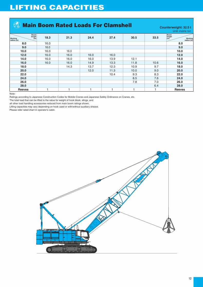
Boom length
Working (m)radius (m)
18.3 21.3 24.4 27.4 30.5 33.5Boomlength(m) Working
radius (m)
8.0 16.0 8.09.0 16.0 9.0
10.0 16.0 16.0 10.012.0 16.0 16.0 16.0 16.0 12.014.0 16.0 16.0 16.0 13.9 12.1 14.016.0 16.0 16.0 14.9 13.3 11.8 10.6 16.018.0 14.3 13.7 12.3 10.9 9.7 18.020.0 12.0 11.3 10.0 9.0 20.022.0 10.4 9.3 8.3 22.024.0 8.5 7.6 24.026.0 7.8 7.0 26.028.0 6.4 28.0
Reeves 1 1 1 1 1 1 ReevesNote:Ratings according to Japanese Construction Codes for Mobile Cranes and Japanese Safety Ordinance on Cranes, etc.The total load that can be lifted is the value for weight of hook block, slings, and all other load handling accessories reduced from main boom ratings shown.Lifting capacities may vary depending on hook used or with/without auxiliary sheave. Please refer rated chart in operator’s cabin.
Main Boom Rated Loads For Clamshell Counterweight: 32.5 tUnit: metric ton
LIFTING CAPACITIES

13
SUPPLEMENTAL DATA FOR BUCKET RATING CHART· Operating radius is the horizontal distance from centerline of rotation to a vertical line through the center of gravity of the load.
· Deduct weight of hook block(s), slings and all other load handling accessories from main boom ratings shown.
· Ratings shown are based on freely suspended loads and make no allowance for such factors as wind effect on lifted load, ground conditions, out-of-level, operating speeds or any other condition that could be detrimental to the safe operation of this equipment.The operator, therefore, has the responsibility to judge the existing conditions and reduce lifted loads and operating speeds accordingly.
· Ratings are for operation on a firm and level surface, up to 1% gradient.
· At radii and boom lengths where no ratings are shown on chart, operation is not intended nor approved.
· Boom inserts and guy lines must be arranged as shown in the "operator's manual".
· Boom hoist reeving is 12 part line.
· Gantry must be in raised position for all conditions.
· Boom backstops are required for all boom lengths.
· The boom should be erected over the front of the crawlers, not laterally.
(Main boom)
· The total load that can be lifted is the value for weight of hook block, slings, and all other load handling accessories deducted from main boom ratings shown.
(Main boom with auxiliary sheave frame)
· The total load that can be lifted is the value for weight of main hook block, slings, and all other load handling accessories deducted from main boom with auxiliary sheave ratings shown.
(Auxiliary sheave)
· The total load that can be lifted is the value for weight of hook block, slings, and all other load handling accessories deducted from auxiliary sheave ratings shown.
Main hoist loads (Third Drum)No. of Parts of Line 1 2 3 4 5 6
Maximum Loads (kN) 132 265 397 530 662 794Maximum Loads (t) 13.5 27.0 40.5 54.0 67.5 81.0
No. of Parts of Line 7 8Maximum Loads (kN) 927 981Maximum Loads (t) 94.5 100.0
Auxiliary hoist loads (For Bucket)No. of Parts of Line 1+1
Maximum Loads (kN) 319Maximum Loads (t) 32.5
Weight of hook blockHook Block 120 t 70 t / 50 t 16 tWeight (t) 1.6 1.2 0.5
Operation of this equipment in excess of rated loads or disregard of instruction voids the warranty.

14
LIFTING CAPACITIES
Boomlength
Load (m)radius (m)
18.3 21.3 24.4 27.4 30.5 33.5Boomlength (m) Load radius (m)
6.0 6.3m/32.5 6.8m/32.5 6.07.0 32.5 32.5 7.3m/32.5 7.9m/32.5 7.08.0 32.5 32.5 32.5 32.5 8.4m/32.5 8.9m/32.5 8.09.0 32.5 32.5 32.5 32.5 32.5 32.5 9.0
10.0 32.5 32.5 32.5 32.5 32.5 32.5 10.012.0 32.5 32.5 32.5 32.5 32.5 32.5 12.014.0 26.7 26.5 26.3 26.2 26.0 25.9 14.016.0 22.0 21.9 21.7 21.6 21.3 21.2 16.018.0 15.9 18.5 18.2 18.2 17.9 17.8 18.020.0 18.8m/13.4 14.9 15.7 15.6 15.3 15.2 20.022.0 21.4m/12.4 13.7 13.5 13.2 13.1 22.024.0 10.6 11.9 11.6 11.4 24.026.0 24.1m/10.4 10.1 10.2 10.0 26.028.0 26.7m/9.4 9.0 8.9 28.030.0 29.3m/8.2 7.9 30.032.0 6.9 32.0
Reeves 1+1 1+1 1+1 1+1 1+1 1+1 ReevesNote:Ratings according to Japanese Construction Codes for Mobile Cranes and Japanese Safety Ordinance on Cranes, etc.The total load that can be lifted is the value for weight of hook block, slings, and all other load handling accessories reduced from main boom ratings shown.Lifting capacities may vary depending on hook used or with/without auxiliary sheave. Please refer rated chart in operator’s cabin.
Counterweight: 32.5 tUnit: metric ton
Bucket Rating Charts Auxiliary Sheave Lifting Capacities (with Aux. Sheave, 16t Aux. Hook Blocks, without Main Hook Block)

15
· Operating radius is the horizontal distance from centerline of rotation to a vertical line through the center of gravity of the load.
· Deduct weight of hook block(s), slings and all other load handling accessories from main boom ratings shown.
· Condition of barge stability this rating chart were determined under the condition below. The stability of barge shall meet below condition. During operation the machinery static inclination against horizontal level.
(A) Both sides (right & left) of machine Maximum inclination shall be within 1.5 Degrees (B) Front & backward of macine Maximum inclination shall be within 3.0 Degrees
· Working area shall be inshore and smooth water.
· Applicable regulations for structure japanese construction codes for mobil crane
※ Regulation of class of shipping (abs, lloyd, bv, nk, etc) are not adapted.
· At radii and boom lengths where no ratings are shown on chart, operation is not intended nor approved.
· Boom inserts and guy lines must be arranged as shown in the "operator's manual".
· Boom hoist reeving is 12 part line.
· Gantry must be in raised position for all conditions.
· Boom backstops are required for all boom lengths.
SUPPLEMENTAL DATA FOR BARGE RATING CHART· The boom should be erected over the front of the crawlers, not laterally.
· Ratings inside of boxes are limited by strength of materials.
· The minimum rated load is 2.0 (ton).
· The machinery should be fastened to the deck of the barge to prevent tip over and sliding.
· Towing area Towing area shall be within coastal area and quiet wave condition. Offshore and open sea is not considered for this machinery. Depend on the height of wave, counterweight shall be reduced during towing.
(Crane boom)
· The total load that can be lifted is the value for weight of hook block, slings, and all other load handling accessories deducted from main boom ratings shown.
<Reference Information>Main hoist loads
No. of Parts of Line 1 2 3 4 5Maximum Loads (kN) 157 294 441 588 686Maximum Loads (t) 16.0 30.0 45.0 60.0 70.0
Auxiliary hoist loadsNo. of Parts of Line 1 2
Maximum Loads (kN) 157 294Maximum Loads (t) 16.0 30.0
Weight of hook blockHook Block 70 t 50 t Ball HookWeight (t) 1.2 1.2 0.45
Operation of this equipment in excess of rated loads or disregard of instruction voids the warranty.
Direction of Front and Rearfor Machinery
Direction of Right and Leftfor Machinery
(A) (B)
1.5°
1.5° 3°

16
LIFTING CAPACITIES
Boom length
Load (m)radius (m)
18.3 21.3 24.4 27.4 30.5 33.5 36.6 39.6Boomlength(m) Load
radius (m)
6.0 70.0 6.07.0 60.0 59.8 7.08.0 50.0 49.8 49.6 8.09.0 42.8 42.6 42.4 42.2 9.0
10.0 37.0 36.8 36.6 36.5 36.3 36.2 10.012.0 28.6 28.4 28.2 28.0 27.8 27.7 27.6 27.5 12.014.0 23.3 23.1 23.0 22.9 22.7 22.6 22.5 22.4 14.016.0 19.5 19.3 19.2 19.1 18.8 18.7 18.6 18.5 16.018.0 16.5 16.4 16.3 16.0 15.9 15.8 15.7 18.020.0 14.3 14.2 13.9 13.8 13.7 13.6 20.022.0 12.6 12.4 12.1 12.0 11.9 11.8 22.024.0 10.5 10.4 10.3 10.2 10.1 24.026.0 9.6 9.5 9.4 9.3 26.028.0 8.6 8.4 8.4 28.030.0 7.8 7.6 7.5 30.032.0 6.8 6.8 32.034.0 6.2 34.0
Note:Ratings according to Japanese Construction Codes for Mobile Cranes and Japanese Safety Ordinance on Cranes, etc.The total load that can be lifted is the value for weight of hook block, slings, and all other load handling accessories reduced from main boom ratings shown.Lifting capacities may vary depending on hook used or with/without auxiliary sheave. Please refer rated chart in operator’s cabin.
Barge Rating Chart Crane Boom Lifting Capacities Unit: metric tons

17
TRANSPORTATION PLAN
Name Dimension (mm) Weight(kg)
Base Machine· Gantry· Crawler· Wire rope(Front /boom hoist)
74,100
Base Machine· Gantry· Wire rope(Front / rear / boom hoist)
· Without crawler· Without auxiliary platform
· Without duct
46,900
Base Machine· Wire rope(Front / rear / boom hoist)
· Without gantry· Without crawler· Without auxiliary platform
· Without duct
44,400
Crawler
13,600 x 2
9,5303,480
6,320
4,01
0
4,01
0
9,5303,490
3,260
3,50
0
3,50
0
5,590
7,8903,490
3,260
3,22
0
3,22
0
5,590
7,870 1,330
1,39
0
1,39
0

18

19

20

21
PARTS AND ATTACHMENTS
Base MachineGantry, Crawler, Wire rope (Front /boom hoist),Weight: 74,100 kg Width: 6,320 mm
CrawlerWeight: 13,600 kg
Counterweight No.1Weight: 12,500 kg
Counterweight No.2Weight: 10,000 kg
Counterweight No.3Weight: 10,000 kg
Boom TopWeight: 2,840 kg
Boom Top (with aux. sheave)Weight: 4,130 kg
Boom BaseWeight: 2,450 kg
6.1 m (20 ft) Boom InsertWeight: 810 kg
3.0 m (10 ft) Boom InsertWeight: 500 kg
Gantry (with lower spreader)Weight: 2,500 kg

22
9.1 m (30 ft) Boom InsertWeight: 1,130 kg
Crane BackstopWeight: 330 kg
Auxiliary SheaveWeight: 940 kg
Boom Hoist Upper SpreaderWeight: 480 kg
16 t Ball HookWeight: 460 kg
50 t HookWeight: 1,200 kg
120 t HookWeight: 1,550 kg
70 t HookWeight: 1,200 kg
φ

Hydraulic Crawler Crane
Model : BMS1200HD
17-1, Higashigotanda 2-chome, Shinagawa-ku,Tokyo 141-8626 JAPAN
Note: This catalog may contain photographs of machines with specifications, attachments and optional equipment not certified for operation in your country. Please consult KOBELCO for those items you may require. Due to our policy of continual product improvements all designs and specifications are subject to change without advance notice.Copyright by KOBELCO CRANES CO., LTD. No part of this catalog may be reproduced in any manner without notice.
Tel: +81-3-5789-2130 Fax: +81-3-5789-3372URL: http://www.kobelco-cranes.com/
Bulletin No. BMS1200HD-SPEC-NR1
Inquiries To :
Max. Lifting Capacity: 120 t x 5 mMax. Crane Boom Length: 61.0 m
KOBELCO is the corporate mark used by Kobe Steel on a variety of productsand in the names of a number of Kobe Steel Group companies.
130301F Printed in Japan