Embed Size (px)
Citation preview

1146 JOURNAL OF MICROELECTROMECHANICAL SYSTEMS, VOL. 21, NO. 5, OCTOBER 2012
Hydrogel-Based Tunable-Focus Liquid MicrolensArray With Fast Response Time
Difeng Zhu, Chi-Wei Lo, Chenhui Li, and Hongrui Jiang, Senior Member, IEEE
Abstract—We present a hydrogel-driven focus-tunable liquidmicrolens array on a curvilinear surface with much faster re-sponse time than previously reported. Water–oil interfaces pinnedat polymer apertures serve as microlenses. Thermoresponsivepoly(N-isopropylacrylamide) hydrogel incorporating glycidyl-methacrylate-functionalized graphene oxide is employed to pro-vide faster actuation for focal length tuning. Thermoelectricmodules based on Peltier effect were implemented to enhance theheat transfer to and dissipation from the hydrogel actuators. Theaverage response time improves to 5 s, and the focal length rangesfrom 7 to 120 mm. Simulations were performed to characterizethe thermal behavior of the microlens array during actuation. Themicrolens array is also demonstrated with an ability to be remotelycontrolled by infrared light. [2011-0285]
Index Terms—Curvilinear surface, microlens array, responsetime, thermal analysis, tunable focus.
I. INTRODUCTION
A S AN indispensable component in imaging and mi-croscopy, microlens plays an important role in biomedi-
cal, industrial, and military applications [1]–[6]. Furthermore,microlenses and microlens arrays with more functionalitiessuch as focus tunability, large field of view (FOV), and struc-tural robustness are highly desired [1], [3], [6]–[8]. Comparedto tunable microlenses based on other mechanisms such asliquid crystal [3], electrowetting [9], fluidic pressure [10],and electrochemical reaction [2], hydrogel microlenses andmicrolens arrays have shown great promise, since they offerlarge tuning range, good biological compatibility, and relativeconvenience to integrate with optics. Moreover, the hydrogel-driven microlens array could be fabricated onto nonplanarsurfaces with large FOV, which could have greater scope of ap-plications [7], [12]–[14]. Nevertheless, relatively slow response
Manuscript received September 23, 2011; revised March 30, 2012; acceptedApril 7, 2012. Date of publication May 11, 2012; date of current versionSeptember 27, 2012. This work was supported mainly by the National Sci-ence Foundation under Grant ECCS 0745000 and partly by the WisconsinInstitutes for Discovery and the Wallace H. Coulter Foundation. Subject EditorO. Solgaard.
D. Zhu was with the Department of Electrical and Computer Engineering,University of Wisconsin, Madison, WI 53706 USA. He is now with MicronTechnology, Inc., Boise, ID 83705 USA (e-mail: [email protected]).
C.-W. Lo was with the Materials Science Program, University of Wisconsin,Madison, WI 53706 USA. He is now with Applied Materials Inc., Santa Clara,CA 95054 USA (e-mail: [email protected]).
C. Li is with the Department of Electrical and Computer Engineering,University of Wisconsin, Madison, WI 53706 USA (e-mail: [email protected]).
H. Jiang is with the Department of Electrical and Computer Engineering, theMaterials Science Program, the Eye Research Institute, and the Department ofBiomedical Engineering, University of Wisconsin, Madison, WI 53706 USA(e-mail: [email protected]).
Color versions of one or more of the figures in this paper are available onlineat http://ieeexplore.ieee.org.
Digital Object Identifier 10.1109/JMEMS.2012.2196492
time on the order of tens of seconds could limit their potentialapplications.
Here, we present a thermoresponsive-hydrogel-actuated mi-crolens array on a hemispheric dome with much faster responsetime than previously reported. The improvement is attributed totwo factors. First, glycidyl methacrylate (GMA)-functionalizedgraphene oxide (GO) was incorporated into the thermore-sponsive poly(N-isopropylacrylamide) (PNIPAAm) hydrogel[15] (called GO-GMA hydrogel). This GO-GMA hydrogelhas much faster thermal response compared to the originalPNIPAAm hydrogel and is employed to provide more effectiveactuation for focal length tuning. Second, the delivery and dissi-pation of heat to the hydrogel actuators are much enhanced. Theslow response time of the previously reported hydrogel-drivenliquid microlenses [7], [12], [13] is mainly due to the relianceon the natural heat dissipation through the structures when thehydrogel needs to be cooled down. We applied thermoelectricmodules based on the Peltier effect and assembled them closeto the hydrogel actuators to facilitate the local cooling process.These modules also improved the local heating process of thehydrogel. The microlens array was fabricated on a curvilinearsurface (a hemispherical shell) to achieve large FOV, utilizing arelatively simple process.
Simulations and experiments on the thermal stress andcrosstalk between adjacent microlenses during the actuationprocesses were performed in order to further characterize thetuning behavior of the microlens array. It was demonstrated thatthe operation of the microlens array was not affected by thethermal disturbance such as thermal stress and crosstalk duringthe actuation.
Owing to the strong infrared (IR) light absorption in GOwithin the hydrogel networks and the photothermal energy con-version capability of GO to trigger the hydration–dehydrationtransition, the GO-GMA-hydrogel-based microlens array canalso be remotely controlled by IR irradiation, which could havemore potential applications [15], [16]. Characterization of theIR-responsive microlens array is also discussed.
II. PRINCIPLE AND STRUCTURE
Fig. 1(a) and (b) shows the 3-D schematics of one GO-GMA-hydrogel-driven liquid microlens in an array fabricated on ahemispherical shell. A cavity, defined by a polydimethylsilox-ane (PDMS) polymer substrate and a PDMS aperture slip, isfilled with water. Silicone oil is added on top of the water toprevent evaporation and serve as the lens material due to itshigher refractive index (1.48) compared to that of water (1.33).The sidewall of the aperture slip is treated hydrophilic, while
1057-7157/$31.00 © 2012 IEEE
ZHU et al.: HYDROGEL-BASED TUNABLE-FOCUS LIQUID MICROLENS ARRAY WITH FAST RESPONSE TIME 1147
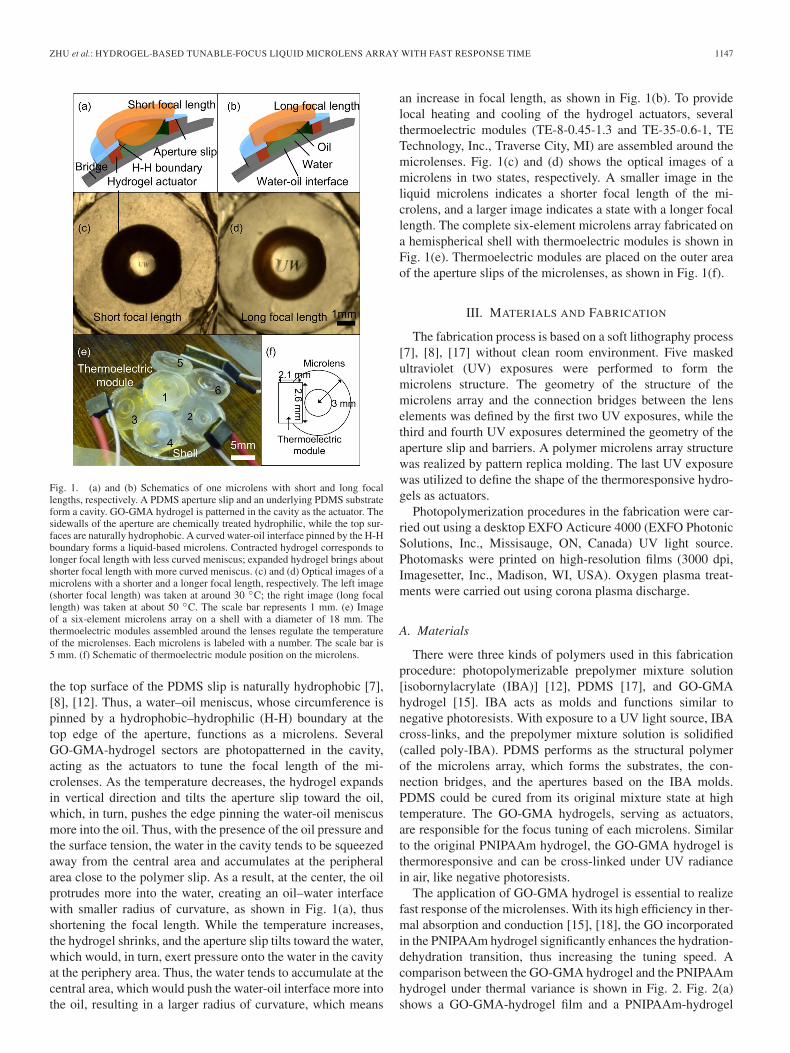
Fig. 1. (a) and (b) Schematics of one microlens with short and long focallengths, respectively. A PDMS aperture slip and an underlying PDMS substrateform a cavity. GO-GMA hydrogel is patterned in the cavity as the actuator. Thesidewalls of the aperture are chemically treated hydrophilic, while the top sur-faces are naturally hydrophobic. A curved water-oil interface pinned by the H-Hboundary forms a liquid-based microlens. Contracted hydrogel corresponds tolonger focal length with less curved meniscus; expanded hydrogel brings aboutshorter focal length with more curved meniscus. (c) and (d) Optical images of amicrolens with a shorter and a longer focal length, respectively. The left image(shorter focal length) was taken at around 30 ◦C; the right image (long focallength) was taken at about 50 ◦C. The scale bar represents 1 mm. (e) Imageof a six-element microlens array on a shell with a diameter of 18 mm. Thethermoelectric modules assembled around the lenses regulate the temperatureof the microlenses. Each microlens is labeled with a number. The scale bar is5 mm. (f) Schematic of thermoelectric module position on the microlens.
the top surface of the PDMS slip is naturally hydrophobic [7],[8], [12]. Thus, a water–oil meniscus, whose circumference ispinned by a hydrophobic–hydrophilic (H-H) boundary at thetop edge of the aperture, functions as a microlens. SeveralGO-GMA-hydrogel sectors are photopatterned in the cavity,acting as the actuators to tune the focal length of the mi-crolenses. As the temperature decreases, the hydrogel expandsin vertical direction and tilts the aperture slip toward the oil,which, in turn, pushes the edge pinning the water-oil meniscusmore into the oil. Thus, with the presence of the oil pressure andthe surface tension, the water in the cavity tends to be squeezedaway from the central area and accumulates at the peripheralarea close to the polymer slip. As a result, at the center, the oilprotrudes more into the water, creating an oil–water interfacewith smaller radius of curvature, as shown in Fig. 1(a), thusshortening the focal length. While the temperature increases,the hydrogel shrinks, and the aperture slip tilts toward the water,which would, in turn, exert pressure onto the water in the cavityat the periphery area. Thus, the water tends to accumulate at thecentral area, which would push the water-oil interface more intothe oil, resulting in a larger radius of curvature, which means
an increase in focal length, as shown in Fig. 1(b). To providelocal heating and cooling of the hydrogel actuators, severalthermoelectric modules (TE-8-0.45-1.3 and TE-35-0.6-1, TETechnology, Inc., Traverse City, MI) are assembled around themicrolenses. Fig. 1(c) and (d) shows the optical images of amicrolens in two states, respectively. A smaller image in theliquid microlens indicates a shorter focal length of the mi-crolens, and a larger image indicates a state with a longer focallength. The complete six-element microlens array fabricated ona hemispherical shell with thermoelectric modules is shown inFig. 1(e). Thermoelectric modules are placed on the outer areaof the aperture slips of the microlenses, as shown in Fig. 1(f).
III. MATERIALS AND FABRICATION
The fabrication process is based on a soft lithography process[7], [8], [17] without clean room environment. Five maskedultraviolet (UV) exposures were performed to form themicrolens structure. The geometry of the structure of themicrolens array and the connection bridges between the lenselements was defined by the first two UV exposures, while thethird and fourth UV exposures determined the geometry of theaperture slip and barriers. A polymer microlens array structurewas realized by pattern replica molding. The last UV exposurewas utilized to define the shape of the thermoresponsive hydro-gels as actuators.
Photopolymerization procedures in the fabrication were car-ried out using a desktop EXFO Acticure 4000 (EXFO PhotonicSolutions, Inc., Missisauge, ON, Canada) UV light source.Photomasks were printed on high-resolution films (3000 dpi,Imagesetter, Inc., Madison, WI, USA). Oxygen plasma treat-ments were carried out using corona plasma discharge.
A. Materials
There were three kinds of polymers used in this fabricationprocedure: photopolymerizable prepolymer mixture solution[isobornylacrylate (IBA)] [12], PDMS [17], and GO-GMAhydrogel [15]. IBA acts as molds and functions similar tonegative photoresists. With exposure to a UV light source, IBAcross-links, and the prepolymer mixture solution is solidified(called poly-IBA). PDMS performs as the structural polymerof the microlens array, which forms the substrates, the con-nection bridges, and the apertures based on the IBA molds.PDMS could be cured from its original mixture state at hightemperature. The GO-GMA hydrogels, serving as actuators,are responsible for the focus tuning of each microlens. Similarto the original PNIPAAm hydrogel, the GO-GMA hydrogel isthermoresponsive and can be cross-linked under UV radiancein air, like negative photoresists.
The application of GO-GMA hydrogel is essential to realizefast response of the microlenses. With its high efficiency in ther-mal absorption and conduction [15], [18], the GO incorporatedin the PNIPAAm hydrogel significantly enhances the hydration-dehydration transition, thus increasing the tuning speed. Acomparison between the GO-GMA hydrogel and the PNIPAAmhydrogel under thermal variance is shown in Fig. 2. Fig. 2(a)shows a GO-GMA-hydrogel film and a PNIPAAm-hydrogel

1148 JOURNAL OF MICROELECTROMECHANICAL SYSTEMS, VOL. 21, NO. 5, OCTOBER 2012
Fig. 2. Comparison of the changes in volume between GO-GMA hydro-gel and PNIPAAm hydrogel under thermal variance. (a) GO-GMA- andPNIPAAm-hydrogel films initially in a water-based aqueous environment.(b) GO-GMA- and PNIPAAm-hydrogel films after being heated at 65 ◦C for6 s. The scale bar represents 5 mm. (c) Dynamic change in the normalized areasof the films with time.
film with the same initial diameter of 10 mm; both were im-mersed in water. Then, after being heated at 65 ◦C on a hot platefor 6 s, the statuses of the hydrogel films are shown in Fig. 2(b).A much more distinct change in area of the GO-GMA-hydrogelfilm was observed as compared to the PNIPAAm-hydrogel film.The dynamic change in the normalized areas of both filmsis plotted in Fig. 2(c). Heating at 65 ◦C started at 0 s. TheGO-GMA hydrogel contracted much faster than PNIPAAm,and the shrinkage in area reaches the maximum at around 5 s.As indicated in this experiment, microlens with GO-GMA-hydrogel actuators would have faster tuning speed than thatwith PNIPAAm hydrogel. The functionality of GO-GMA wastested multiple times, and no apparent hysteresis was observed.
B. Fabrication Process
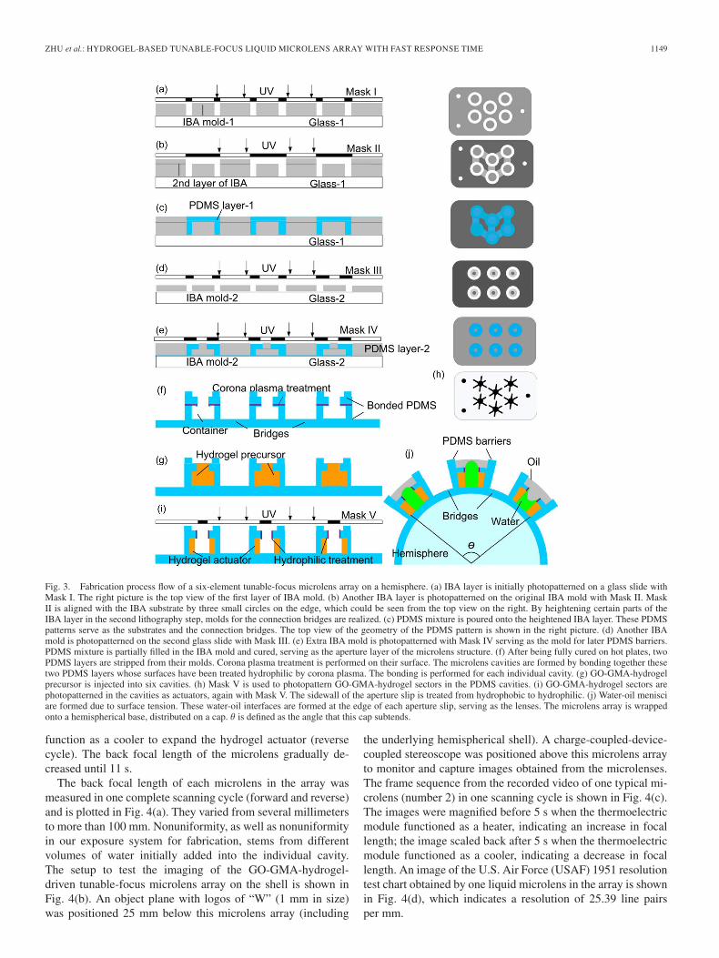
The fabrication process of the GO-GMA-hydrogel-drivenmicrolens array is shown in Fig. 3, leveraging the method thatwe previously reported in [8]. First, the IBA substrate mold wasformed in a polycarbonate cartridge well (40 mm × 22 mm,HybriWells, Grace Bio-Labs, Inc., Bend, OR, USA). Spacersthat are 250 μm thick (double-sided adhesive tape; 3 M Corpo-rate, St. Paul, MN) were placed in the cartridge. An IBA-basedprepolymer mixture solution was flowed into the well and wasexposed to UV light (intensity of UV = 9 mW/cm2; time t =20 s) with Mask I to form a poly-IBA array of wells, as shownin Fig. 3(a) (top view shown on the right). During the exposure,the mask is pushed against the top surface of the cartridge well;therefore, the height of the patterned IBA was defined by thethickness of the spacers. The bottom liner plate of the cartridgewas then peeled off. Unpolymerized prepolymer solution wasrinsed away with ethanol. Another layer of IBA polymer wassubsequently formed onto the patterned structures under UVradiance (intensity I = 9 mW/cm2; time t = 20 s) with Mask IIto increase the height of selected patterns with 200-μm-thickspacers, corresponding to the ultimate connection bridge struc-tures, as shown in Fig. 3(b). Mask II was aligned on top ofthe second cartridge with the patterned IBA molding struc-tures utilizing three small circles at the edge, as shown in theright picture (top view) of Fig. 3(b). A similar procedure wasexecuted on a glass slide to form another mold of 120 μmin thickness, corresponding to the aperture slip, as shown in
Fig. 3(d). An extra poly-IBA layer with a height of around200 μm was photopatterned on the original aperture slip patternwith Mask IV, as shown in Fig. 3(e). This layer served as themold for PDMS barriers, which would prevent oil leakage fromthe completed device. Both IBA patterns were transferred toPDMS layers functioning as the substrate and the aperture slip,respectively, as shown in Fig. 3(c) and (e). The liquid levelof the PDMS mixture was lower than the IBA mold to formthrough-holes as the apertures. The PDMS mixture was thencured on a hot plate at 65 ◦C for 4 h. Next, two fully curedPDMS layers were peeled off from their respective molds.
After the inner surfaces of the cavities were treated fromhydrophobic to hydrophilic by corona plasma discharge, twoPDMS layers were bonded together [19], as shown in Fig. 3(f),to form the structure. Then, the bonded PDMS structure waspressed by 20 lb of loads for one day, in order to prevent leakagebetween the bonded layers.
Next, a GO-GMA-hydrogel precursor was injected into thecavities, as shown in Fig. 3(g), and was photopatterned underUV light with Mask V, as shown in Fig. 3(h). Three lines acrossthe circle in the mask would divide the GO-GMA hydrogel intosix sectors in the cavity. In this way, surfaces of the hydrogelactuators were increased, which exhibited less resistance andmore freedom in actuation procedure. As a result, the actuationforce and speed provided by the hydrogel were improved, andthus, the response time was decreased correspondingly [20].The intensity used in lithography was 28 mW/cm2, whichis about twice of that used on PNIPAAm-hydrogel patterns.The exposure time was extended to 25 s to ensure full cross-linking of the GO-GMA hydrogel. Non-cross-linked hydrogelprecursor was flushed away by ethanol.
After six sectors of GO-GMA hydrogel were formed in thecavities after the fifth UV exposure, the sidewall of the apertureslip was treated by corona plasma discharge to be hydrophilicto pin the water-oil menisci, as shown in Fig. 3(i).
Then, the planar microlens array with a soft PDMS substratewas wrapped onto a hemisphere base. Finally, each cavity wasfilled with water and covered by silicone oil, forming the water-oil interfaces, as shown in Fig. 3(j). The diameter of eachmicrolens was 1.8 mm. Each cavity was 250 μm in depth and 4mm in diameter. The connection bridges were around 200 μmthick, 0.8 mm wide, and 0.8 mm long. These connectionbridges, which are much thinner than the lens structure, wouldeffectively absorb the stress owing to the wrapping [8]. θ,defined as the angle that the lens array structure subtends inFig. 3(j), was 118 ◦C, hence large FOV as compared to a planarlens array. The shape of the original water-oil interfaces wasdetermined by the volume of water filled.
IV. OPTICAL CHARACTERIZATION
Back focal length measurements and imaging characteriza-tion of the GO-GMA-hydrogel-driven liquid microlenses werethen performed. First, the microlens under test was set at theshortest focal length (0 s). Then, a thermoelectric module waspositioned near the microlens [Fig. 1(f)], operating as a heaterto contract the hydrogel for 5 s (forward cycle). Subsequently(at 5 s), the thermoelectric module was reverse connected to
ZHU et al.: HYDROGEL-BASED TUNABLE-FOCUS LIQUID MICROLENS ARRAY WITH FAST RESPONSE TIME 1149
Fig. 3. Fabrication process flow of a six-element tunable-focus microlens array on a hemisphere. (a) IBA layer is initially photopatterned on a glass slide withMask I. The right picture is the top view of the first layer of IBA mold. (b) Another IBA layer is photopatterned on the original IBA mold with Mask II. MaskII is aligned with the IBA substrate by three small circles on the edge, which could be seen from the top view on the right. By heightening certain parts of theIBA layer in the second lithography step, molds for the connection bridges are realized. (c) PDMS mixture is poured onto the heightened IBA layer. These PDMSpatterns serve as the substrates and the connection bridges. The top view of the geometry of the PDMS pattern is shown in the right picture. (d) Another IBAmold is photopatterned on the second glass slide with Mask III. (e) Extra IBA mold is photopatterned with Mask IV serving as the mold for later PDMS barriers.PDMS mixture is partially filled in the IBA mold and cured, serving as the aperture layer of the microlens structure. (f) After being fully cured on hot plates, twoPDMS layers are stripped from their molds. Corona plasma treatment is performed on their surface. The microlens cavities are formed by bonding together thesetwo PDMS layers whose surfaces have been treated hydrophilic by corona plasma. The bonding is performed for each individual cavity. (g) GO-GMA-hydrogelprecursor is injected into six cavities. (h) Mask V is used to photopattern GO-GMA-hydrogel sectors in the PDMS cavities. (i) GO-GMA-hydrogel sectors arephotopatterned in the cavities as actuators, again with Mask V. The sidewall of the aperture slip is treated from hydrophobic to hydrophilic. (j) Water-oil menisciare formed due to surface tension. These water-oil interfaces are formed at the edge of each aperture slip, serving as the lenses. The microlens array is wrappedonto a hemispherical base, distributed on a cap. θ is defined as the angle that this cap subtends.
function as a cooler to expand the hydrogel actuator (reversecycle). The back focal length of the microlens gradually de-creased until 11 s.
The back focal length of each microlens in the array wasmeasured in one complete scanning cycle (forward and reverse)and is plotted in Fig. 4(a). They varied from several millimetersto more than 100 mm. Nonuniformity, as well as nonuniformityin our exposure system for fabrication, stems from differentvolumes of water initially added into the individual cavity.The setup to test the imaging of the GO-GMA-hydrogel-driven tunable-focus microlens array on the shell is shown inFig. 4(b). An object plane with logos of “W” (1 mm in size)was positioned 25 mm below this microlens array (including
the underlying hemispherical shell). A charge-coupled-device-coupled stereoscope was positioned above this microlens arrayto monitor and capture images obtained from the microlenses.The frame sequence from the recorded video of one typical mi-crolens (number 2) in one scanning cycle is shown in Fig. 4(c).The images were magnified before 5 s when the thermoelectricmodule functioned as a heater, indicating an increase in focallength; the image scaled back after 5 s when the thermoelectricmodule functioned as a cooler, indicating a decrease in focallength. An image of the U.S. Air Force (USAF) 1951 resolutiontest chart obtained by one liquid microlens in the array is shownin Fig. 4(d), which indicates a resolution of 25.39 line pairsper mm.

1150 JOURNAL OF MICROELECTROMECHANICAL SYSTEMS, VOL. 21, NO. 5, OCTOBER 2012
Fig. 4. Dynamic change in the back focal length of each microlens, as labeledin Fig. 1(c), in one scanning cycle. (b) Three-dimensional schematic of thesetup for testing the imaging capability of the microlens array. (c) Framesequence of the focused images from one typical microlens (number 2) in thismicrolens array in one scanning cycle. Thermoelectric module is convertedfrom a heater to a cooler at 5 s. The real images are magnified before 5 s.Then, the image shrinks until 11 s. The scale bar is 1 mm. (d) Image of USAF1951 resolution test chart obtained by one liquid microlens. The object distanceis 36 mm with a focal length of 10 mm. The smallest feature is 25.39 line pairsper mm, which corresponds to Group 4, Element 5 in the chart.
V. SIMULATION OF THERMAL BEHAVIOR
Finite-element method (ANSYS; ANSYS, Inc., Canonsburg,PA) was employed to quantitatively analyze the thermal be-havior of the GO-GMA-hydrogel microlens array involvingthe thermoelectric modules. A model of the six-element mi-crolens array structure, including the PDMS substrates andbridges, was first established in ANSYS. The parameters setfor this model were as follows: PDMS structural material;mass density: 0.97 kg/m3; Young’s modulus: 750 kPa; Poissonratio: 0.49; thermal conductivity: 0.15 W/m · K; specific heat:1.46 kJ/kg · K; thermal expansion ratio of 331 ppm; averageconvection heat transfer coefficient: 10 W · m−2 [21], [22];environment temperature and initial temperature condition:23 ◦C; diameter and thickness of one complete circular polymerstructure representing the fringe and the substrate of a mi-crolens: 3 and 0.5 mm, respectively; diameter and thickness of achamber where the microlens (water-oil interface) resides: 1.5and 0.25 mm, respectively; and connection bridge structures:1.5 mm × 1.2 mm × 0.25 mm.
A. Heat Delivery and Conduction
With the thermoelectric modules, local thermal delivery andconduction are significantly enhanced during the actuation pro-cedure of the microlens array. As a result, the response time ofthe lenses is improved. ANSYS was employed to quantitativelyanalyze the heat conduction in the structure involving thethermoelectric modules. A model of the six-element microlensarray structure, including the PDMS substrates and bridges,with individual thermoelectric module was established inANSYS. Thermal transient analysis was then performed. Tun-ing from short focal length to long focal length (forward cycle)and that from long focal length to short focal length (reversecycle) were simulated separately, as shown in Fig. 5. Thermal
boundary condition was applied at the outer area of each lens tomimic the functionality of the thermoelectric modules [refer toFig. 1(f) for their positions]. The temperature provided by thethermoelectric modules was set as 65 ◦C in the forward cycleand 15 ◦C in the reverse cycle at the bottom of the polymersubstrate. In the forward cycle, the beginning temperature ofthe whole structure was set at 23 ◦C (room temperature), whilein the reverse cycle, it was set at 55 ◦C. Steady temperatureprofiles of the microlens array in the forward and reverse cyclesare shown in Fig. 5(a) and (c), respectively. A point far fromthe thermoelectric module in the inner circular wall where thehydrogel actuator resided was monitored, as shown in Fig. 5(b)(forward cycle) and 5(d) (reverse cycle). In the forward cycle,the point is heated to 39 ◦C within 0.4 s. Similarly, in the reversecycle, the temperature at this point decreases below 23 ◦Cwithin 0.2 s. The simulation results confirm that thermoelectricmodule could rapidly increase or decrease the temperature nearthe hydrogel actuators.
B. Thermal Stress
Since the actuation of the GO-GMA-hydrogel-driven mi-crolens array requires thermal variance, thermal stress, whichcould deform the polymer structure, might potentially degradethe optical performance of the liquid microlenses. Quantitativesimulation of thermal stress based on current microlens struc-ture was thus studied in ANSYS as well. As the highest tem-perature reached in the actuation process by the thermoelectricmodules, 65 ◦C was set as the boundary condition in the model.Only the origin area of this model was fixed as a mechanicalboundary condition in the simulation, which gives enough free-dom for the polymer structure to deform under thermal stress.Simulated displacement of and thermal stress distribution in theplanar six-element microlens array are plotted in Fig. 6(a) and(b), respectively. Most introduced stress is less than 500 Pa,and displacement is relatively small, which generally shouldnot affect the optical performance of the microlens array in thecurrent design. Displacement of and thermal stress distributionin the planar six-element microlens array in wrapping state areshown in Fig. 6(c) and (d), respectively. Fifty millimeters ofdisplacement is applied at the center point of the middle lens.The edge points of the other five periphery lenses are fixedin order to mimic the wrapping behavior. Compared with thedisplacement and the stress induced by wrapping, the thermalstress induced into the microlens structure could be neglected.Even at the central area where we limited the degree of freedom,wrapped structure bears a stress more than 20 times of that ofthermal stress (425 versus 20 kPa). Also noteworthy is that,in Fig. 6(d), the stress induced owing to the wrapping mostlyappears in the thinner connection bridge structures. This isconsistent with our previous report [8] and confirms that thelens structures are relatively intact after the wrapping of thecomplete device onto a curvilinear surface.
C. Thermal Crosstalk Between Adjacent Microlenses
Each microlens in the six-element microlens array can beindividually tuned by its own hydrogel actuator. However,

ZHU et al.: HYDROGEL-BASED TUNABLE-FOCUS LIQUID MICROLENS ARRAY WITH FAST RESPONSE TIME 1151
Fig. 5. (a) Temperature profile obtained from transient analysis in ANSYS of the six-element microlens array during the forward cycle. (b) Dynamic temperaturechange at a point of the hydrogel actuator in the forward cycle. (c) Temperature profile from the transient analysis of the same array during the reverse cycle.(d) Dynamic temperature change at the same point of the hydrogel actuator in the reverse cycle.
Fig. 6. (a) and (b) Displacement and thermal stress profile obtained from staticanalysis of a six-element microlens array in ANSYS. (c) and (d) Displacementof and thermal stress distribution in the planar six-element microlens arrayunder small wrapping force.
the thermal variance that causes one actuator to expand orshrink might affect neighboring hydrogel actuators due to heattransfer. Hence, crosstalk between each microlens may affectthe tuning process when adjacent microlenses are meant tobe tuned at different focal lengths. ANSYS was then used toanalyze thermal crosstalk in the six-element microlens array. Inthis simulation, 65 ◦C was considered the highest temperatureneeded to realize the state with the longest focal length of theGO-GMA-hydrogel-based microlens array, while 15 ◦C wastaken as the lowest temperature boundary loaded to reach theshortest focal length. Three situations regarding the thermalcrosstalk were simulated to exhibit the effect of crosstalk.
The first situation is when the central part is cooled downwith a 15-◦C thermal boundary to reach the shortest focal
length, while adjacent microlenses are heated with a 65-◦Cthermal boundary to achieve the longest focal length. Thiswould be one worst case scenario with the most severe thermalcrosstalk, in which the central microlens might suffer fromshifting from its shortest-focal-length state, owing to thermalcrosstalk from adjacent structures. Obtained from transient andstatic finite-element simulations, the thermal profile of the six-element microlens array in this scenario is shown in Fig. 7(a).The temperature surrounding the GO-GMA hydrogel at thecentral lens is well below 32 ◦C, the lowest critical solution tem-perature (LCST) of the PNIPAAm hydrogel [15], [16], whilethe temperature surrounding the GO-GMA hydrogel at adjacentmicrolenses is well above 32 ◦C, as shown in Fig. 7(a). Thisindicates that the hydrogel actuator at the central lens wouldnot experience any significant shrinkage, thus keeping the lensat its shortest-focal-length state. In contrast, other hydrogelactuators would still be close to their most contracted state,maintaining the longest focal length for their correspondinglenses.
Another situation is simulated as shown in Fig. 7(b). Thecentral microlens is heated with a 65-◦C boundary conditionto trigger the longest-focal-length state while the adjacent mi-crolenses are cooled down with a 15-◦C boundary conditionto achieve the shortest focal length. This would be anotherworst case scenario where the most severe thermal crosstalkwould occur, since the central microlens might potentially bedriven off from its longest-focal-length state by the adjacentcooler temperature. Simulation results from the transient andstatic finite-element analyses are plotted in Fig. 7(b). As canbe seen in the temperature profile, the temperature surroundingthe GO-GMA hydrogel at the central lens is well above 32 ◦C,the LCST of PNIAAm hydrogel, while the temperature at theadjacent lenses is much lower than 32 ◦C. Similar to thediscussion pertaining to the first scenario, the central lens would

1152 JOURNAL OF MICROELECTROMECHANICAL SYSTEMS, VOL. 21, NO. 5, OCTOBER 2012
Fig. 7. Study of the thermal crosstalk between the lenses. (a) Temperatureprofile of the first scenario. The microlens at the center is with a 15-◦C thermalboundary to activate the shortest focal length, and adjacent microlenses are witha 65-◦C thermal boundary to achieve the longest focal length. The hydrogelregion of the central lens is with a temperature below 15 ◦C, which is muchlower than the LCST of the hydrogel, which ensures the short focal length.(b) Temperature profile of the second situation. The microlens at the centeris with a 65-◦C thermal boundary condition, and adjacent microlenses arewith a 15-◦C thermal boundary. The hydrogel region of the central lensis with a temperature above 35 ◦C, which ensures a long focal length.(c) Temperature profile of the third scenario. The central microlens is with a15-◦C thermal boundary, and the three adjacent microlenses are with a65-◦C thermal boundary. (d) Focused image of two adjacent microlenses atroom temperature. Both lenses are at their short-focal-length state. (e) Focusedimage of two adjacent microlenses when the thermoelectric module is activatedas a heater for 5 s. The right microlens reaches its long-focal-length state. Theleft microlens still remains at the short-focal-length state.
still have a focal length close to the longest, while the adjacentones would have focal lengths close to the shortest. The ratioof the temperature change at the central microlens inducedby crosstalk is around 15% in both of these two worst casescenarios.
The third situation simulated is when the central microlensis cooled down with a 15-◦C boundary condition to realizethe shortest focal length, while three adjacent microlenses areheated up to 65 ◦C for the longest focal length. The simulatedtemperature profile resulting from the transient and static finite-element analyses is shown in Fig. 7(c). The central microlensand the two adjacent microlenses without any thermal boundarycondition have a temperature much lower than LCST. The otherthree adjacent microlenses with high-temperature boundarycondition have a temperature well above the LCST.
Experiments were further performed to confirm the resultsfrom simulation. As shown in Fig. 7(d), two adjacentmicrolenses were at their short-focal-length state at room tem-perature. The right microlens was connected with a thermoelec-tric module. When the thermoelectric module functioned as aheater, the right microlens was transformed to a large-focal-length state, as shown in Fig. 7(e). The left microlens kept itsshort-focal-length state during the process.
In summary, we conclude from the simulation and experi-mental results that the microlenses in the six-element array un-der the current design would function without much disturbanceby thermal crosstalk between adjacent microlenses.
D. Effect of Positioning of Thermoelectric Modules
Aside from simulating scenarios with thermoelectric mod-ules on the side of the aperture, we also performed simu-lation with thermoelectric modules positioned directly at thebottom of the liquid microlens onto the back of the PDMSsubstrate.
First, we performed transient analysis similar to that inFig. 5. The bottom surfaces of each microlens are appliedwith thermal boundary conditions to mimic the functionalityof the thermoelectric modules. As in the simulation related toFig. 5, in the forward cycle, the beginning temperature of thewhole structure was set to be 23 ◦C, and at zero time instant,the temperature at all the bottom areas of the lenses became65 ◦C (i.e., thermoelectric module on as heater). Similarly, inthe reverse cycle, the initial temperature of the structure was55 ◦C, and the bottom area of each lens became 15 ◦C (i.e.,thermoelectric module on as cooler). Also similar to Fig. 5(b)and (d), a point at the far end of the hydrogel actuator waschosen to monitor its transient temperature both in the forwardand reverse cycles, respectively. Fig. 8(a) shows the temperatureprofile of the steady state, and Fig. 8(b) shows the transientresponse time of the chosen point in the forward cycle. Fig. 8(c)and (d) shows the result for the reverse cycle. As can be seen,the results are quite comparable with those shown in Fig. 5.
We further studied three scenarios related to the crosstalkwhen the thermoelectric modules are placed directly belowthe lenses, rather than at the outer area. Again, the highesttemperature was set at 65 ◦C, and the lowest temperature wasset at 15 ◦C. The results are shown in Fig. 9. Fig. 9(a) showsthe steady state of the first scenario, where the bottom of thecentral lens was at 15 ◦C and the bottom of the other lenses wasat 65 ◦C. Fig. 9(b) shows the steady state of the second scenarioopposite to the first one, where the bottom of the central lenswas at 65 ◦C and the others at 15 ◦C. Fig. 9(c) correspondsto the third scenario where the bottom of the central lens wasset at 15 ◦C, three others at 65 ◦C, and the last two withoutthermoelectric modules. The results in Fig. 9 are comparableto those in Fig. 7, and similar discussion would apply; hence,similar conclusion can be drawn that the thermal crosstalk isnot significant.
From the simulation shown in Figs. 8 and 9, we can concludethat, in terms of tuning speed and crosstalk, the positioning ofthe thermoelectric modules does not make much difference inlens actuation. This would add flexibility to the system designdependent on the application and other restraints.
VI. IR LIGHT ACTUATION
With large IR light absorption from GO within the hydro-gel networks and superior photothermal conversion [15], [19],[22], the GO-GMA-hydrogel-based microlens array could alsorespond to IR light.
The optical characterization of the IR response of the mi-crolens array is shown in Fig. 10. Initially, the microlens arraywas set at the shortest focal length (0 s). Then, IR light wasturned on to contract the hydrogel for 10 s (forward cycle).Subsequently (at 10 s), IR was turned off (reverse cycle). The

ZHU et al.: HYDROGEL-BASED TUNABLE-FOCUS LIQUID MICROLENS ARRAY WITH FAST RESPONSE TIME 1153
Fig. 8 Transient simulation results with thermal boundaries set at the bottom of each microlens. (a) Temperature profile obtained from the transient analysis ofthe six-element microlens array with thermoelectric modules at the bottom during the forward cycle. (b) Dynamic temperature change at a point of the hydrogelactuator in the forward cycle. (c) Temperature profile from the transient analysis of the same array during the reverse cycle. (d) Dynamic temperature change atthe same point of the hydrogel actuator in the reverse cycle.
Fig. 9 Thermal crosstalk simulation with thermal boundaries set at the bottom of each microlens. (a) Temperature profile of the first scenario with a 15-◦Cthermal boundary at the central microlens and a 65-◦C thermal boundary at adjacent microlenses. The temperature at the hydrogel region of the central lens ismuch lower than the LCST of the hydrogel. (b) Temperature profile of the second situation with a 65-◦C thermal boundary at the central microlens and a 15-◦Cthermal boundary at adjacent microlenses. The temperature at the hydrogel region of the central lens is much higher than the LCST. (c) Temperature profile of thethird scenario. The central microlens is with a 15-◦C thermal boundary, and the three adjacent microlenses are with a 65-◦C thermal boundary.
Fig. 10. (a) Dynamic change in the focal length of each microlens drivenby IR, as labeled in Fig. 1(c), in one scanning cycle. (b) Three-dimensionalschematic of the setup for testing the imaging capability of the microlensarray. (c) Frame sequence of the focused images from one typical microlens(number 4) in the microlens array in one scanning cycle. IR is turned on at 0 sand turned off at 10 s. The real images are magnified before 10 s. Then, theimage shrinks until 16 s. The scale bar is 2 mm.
focal length of the microlens gradually decreased until 16 s.Note that the thermoelectric module operates as a cooler tocompensate for the temperature variance induced in the forwardcycle, resulting in faster response time.
The dynamic change in the focal length of each microlensin the array in one scanning cycle driven by IR is plotted inFig. 10(a). Focal length was recorded at 0, 3, 7, 10, 13, and 16 s,respectively, in one testing cycle. They varied from severalmillimeters to more than 70 mm. At 10 s, the focal lengths ofall microlenses reached their maximum values.
The setup to test the imaging of the GO-GMA-hydrogelmicrolens array on the shell but driven by IR is shown inFig. 10(b), which is similar to the one used for thermal tuningprocedure [Fig. 4(b)]. The size of the object letter “W” was4 mm. The frame sequence from the recorded video of onetypical microlens (number 4) in one scanning cycle is shownin Fig. 10(c). The images were magnified before 10 s when IRwas turned on (intensity: 28 mW/cm2), indicating an increasein focal length; the image scaled back after 11 s when IR wasturned off, indicating a decrease in focal length. During thewhole recording process, the stereoscope was fine-tuned to keepthe images clear.

1154 JOURNAL OF MICROELECTROMECHANICAL SYSTEMS, VOL. 21, NO. 5, OCTOBER 2012
VII. CONCLUSION
In summary, we have demonstrated a liquid-basedGO-GMA-hydrogel-driven microlens array on a curvilinearsurface that processes large-focal-length tuning range, largeFOV, and relatively fast response time. Thermoelectricmodules based on Peltier effect were applied to improve theheat delivery to and dissipation from the hydrogel actuators.The focal length ranged from several millimeters to over100 mm, and the response time improved to 5 s. Finite-elementsimulation was performed to study the thermal response duringthe actuation. Good thermal performance of the microlens arraywas demonstrated by simulation and experiments regardingthermal stress and crosstalk between adjacent microlensesduring the actuation procedure. In addition, it was also shownthat the microlens array could be controlled remotely via IRirradiation. Characterization of the IR response of the microlensarray was performed. The focal length ranged from severalmillimeters to 70 mm, and the average response time was 8 s.
In the future, optical quality of the microlens array such asachromatic aberration caused by light passing through differentlayers of materials (PDMS, water, and oil) with different refrac-tive indices would be further studied. The liquid lens interfaceprofile can be further investigated [24] for more comprehensiveoptical characterization. An IR thermal camera would be usedto monitor the actuation procedure for quantitative analysis.Uniformity of the microlenses will be improved by usingbetter lithography systems and precise pipetting to control thevolume of the water filled into the cavities. Reliability of themicrolenses in terms of number of actuation cycles and shelf-time as well as packaging method to avoid liquid leakage willbe investigated. Microthermoelectric devices will be fabricatedand integrated with the microlenses. Material properties ofGO-GMA hydrogel will be further studied for theoretical focallength calculation. Quantitative structural analysis on actua-tion mechanism will be performed to better characterize thelens tuning process. Multiple waveguides could be employedto simultaneously transmit the signal obtained from differentmicrolenses [25]. Further research on IR would be conducted,since this approach paves a way to intrinsically integrate suchtunable microlenses with other optical components, such asoptical fibers and switches [13].
ACKNOWLEDGMENT
The authors would like to thank Dr. X. Zeng for the technicaldiscussions and Computer Aided Engineering, University ofWisconsin, Madison, for the access to ANSYS 12.1.
REFERENCES
[1] D. Zhang, V. Lien, Y. Berdichevsky, J. Choi, and Y.-H. Lo, “Fluidicadaptive lens with high focal length tunability,” Appl. Phys. Lett., vol. 82,no. 19, pp. 3171–3172, May 2003.
[2] K. Carlson, M. Chidley, K. B. Sung, M. Descour, A. Gillenwater,M. Follen, and R. Richards-Kortum, “In vivo fiber-optic confocal re-flectance microscope with an injection-molded plastic miniature objectivelens,” Appl. Opt., vol. 44, no. 10, pp. 1792–1797, Apr. 2005.
[3] H. Ren and S. T. Wu, “Variable-focus liquid lens by changing aperture,”Appl. Phys. Lett., vol. 86, no. 21, pp. 211107-1–211107-3, May 2005.
[4] C.-C. Cheng, C. A. Chang, C.-H. Liu, and J. A. Yeh, “A tunable liquid-crystal microlens with hybrid alignment,” J. Opt. A, Pure Appl. Opt.,vol. 8, no. 7, pp. 365–369, Jul. 2006.
[5] A. Jain and H. Xie, “Microendoscopic confocal imaging probe based onan LVD microlens scanner,” IEEE J. Sel. Top. Quantum Electron., vol. 13,no. 2, pp. 228–234, Mar./Apr. 2007.
[6] T. Krupenkin, S. Yang, and P. Mach, “Tunable liquid microlens,” Appl.Phys. Lett., vol. 82, no. 3, pp. 316–318, Jan. 2003.
[7] D. Zhu, C. Li, X. Zeng, and H. Jiang, “Tunable-focus microlens arrays oncurved surfaces,” Appl. Phys. Lett., vol. 96, no. 8, p. 081 111, Feb. 2010.
[8] D. Zhu, X. Zeng, C. Li, and H. Jiang, “Focus-tunable microlens arraysfabricated on spherical surfaces,” J. Microelectromech. Syst., vol. 20,no. 2, pp. 389–395, Apr. 2011.
[9] S. Grilli, L. Miccio, V. Vespini, A. Finizio, S. De Nicola, and P. Ferraro,“Liquid micro-lens array activated by selective electrowetting on lithiumniobate substrates,” Opt. Exp., vol. 16, no. 11, pp. 8084–8093, May 2008.
[10] J. Chen, W. S. Wang, J. Fang, and K. Varahramyan, “Variable-focusingmicrolens with microfluidic chip,” J. Micromech. Microeng., vol. 14,no. 5, pp. 675–680, May 2004.
[11] C. A. Lopez, C. C. Lee, and A. H. Hirsa, “Electrochemically activatedadaptive liquid lens,” Appl. Phys. Lett., vol. 87, no. 13, pp. 134102-1–134102-3, Sep. 2005.
[12] L. Dong, A. K. Agarwal, D. J. Beebe, and H. Jiang, “Adaptive liquidmicrolenses activated by stimuli-responsive hydrogels,” Nature, vol. 442,pp. 551–554, Aug. 2006.
[13] X. Zeng and H. Jiang, “Tunable liquid microlens actuated by infraredlight-responsive hydrogel,” Appl. Phys. Lett., vol. 93, no. 15, p. 151 101,Oct. 2008.
[14] Z. Ding and B. Ziaie, “A pH-tunable hydrogel microlens arraywith temperature-actuated light-switching capability,” Appl. Phys. Lett.,vol. 94, no. 8, p. 081 111, Feb. 2009.
[15] C.-W. Lo, D. Zhu, and H. Jiang, “An infrared-light responsive graphene-oxide incorporated poly(N-isopropylacrylamide) hydrogel nanocompos-ite,” Soft Matter, vol. 7, no. 12, pp. 5604–5609, 2011.
[16] C.-W. Lo, D. Zhu, and H. Jiang, “Microfluidic actuators based oninfrared-light responsive PNIPAAm hydrogel nanocomposite incorporat-ing graphene-oxide,” in Proc. 16th Int. TRANSDUCERS, Beijing, China,2011, pp. 2430–2433.
[17] Y. N. Xia and G. M. Whitesides, “Soft lithography,” Annu. Rev. Mater.Sci., vol. 28, pp. 153–184, 1998.
[18] A. A. Balandin, S. Ghosh, W. Bao, I. Calizo, D. Teweldebrhan, F. Miao,and C. N. Lau, “Superior thermal conductivity of graphene,” Nano Lett.,vol. 8, pp. 902–907, 2008.
[19] K. Haubert, T. Drier, and D. Beebe, “PDMS bonding by means of aportable, low-cost corona system,” Lab Chip, vol. 6, no. 12, pp. 1548–1549, 2006.
[20] X. Zeng, C. Li, D. Zhu, H. Cho, and H. Jiang, “Tunable microlensarrays actuated by various thermo-responsive hydrogel structures,”J. Micromech. Microeng., vol. 20, no. 11, p. 115 035, Nov. 2010.
[21] C.-H. Cho, W. Cho, and A. S.-Y. Hwang, “PDMS-glass serpentine mi-crochannel chip for time domain PCR with bubble suppression in sam-ple injection,” J. Micromech. Microeng., vol. 17, no. 9, pp. 1810–1817,Sep. 2007.
[22] Material Property Database, Feb. 2004, [Online]. Available:http://www.mit.edu/~6.777/matprops/pdms.htm
[23] V. Abdelsayed, S. Moussa, H. M. Hassan, H. S. Aluri, M. M. Collinson,and M. S. El-Shall, “Photothermal deoxygenation of graphite oxide withlaser excitation in solution and graphene-aided increase in water temper-ature,” J. Phys. Chem. Lett., vol. 1, no. 19, pp. 2804–2809, 2010.
[24] C. Li, G. Hall, X. Zeng, D. Zhu, K. Eliceiri, and H. Jiang, “Three-dimensional surface profiling and optical characterization of liquid mi-crolens using a Shack–Hartmann wavefront sensor,” Appl. Phys. Lett.,vol. 98, no. 17, p. 171 104, Apr. 2011.
[25] K.-H. Jeong, J. Kim, and L. P. Lee, “Biomimetic artificial compoundeyes,” Science, vol. 312, pp. 557–561, 2006.
Difeng Zhu received the B.S. degree in microelec-tronics from Peking University, Beijing, China, in2007, and the Ph.D. degree in electrical engineeringfrom the University of Wisconsin, Madison, in 2011.
He is currently an R&D Process Engineer withMicron Technology Inc., Boise, ID. His research in-terests include liquid microlens array, microelectron-ics, and microelectromechanical systems fabricationprocess.

ZHU et al.: HYDROGEL-BASED TUNABLE-FOCUS LIQUID MICROLENS ARRAY WITH FAST RESPONSE TIME 1155
Chi-Wei Lo received the B.S. degree in chemistryfrom the National Tsing Hua University, Hsinchu,Taiwan, in 2001, the M.S. degree in materials sciencefrom the University of Pennsylvania, Philadelphia,in 2006, and the Ph.D. degree in materials scienceprogram from the University of Wisconsin, Madison,in 2011.
He is currently an R&D Process Engineer withApplied Materials, Inc., Santa Clara, CA. His re-search interests include graphene-oxide-incorporatedhydrogel nanocomposites, microfluidics, and solar
energy harvesting devices.
Chenhui Li received the B.S. degree in electrical en-gineering from Tsinghua University, Beijing, China,in 2007, and the M.S. degree in electrical and com-puter engineering from the University of Wisconsin,Madison, in 2010, where he is currently workingtoward the Ph.D. degree in electrical engineering.
His research interests include micro-optical imag-ing, liquid focus-variable microlenses, electrowet-ting, and light field cameras.
Hongrui Jiang (S’98–M’02–SM’10) received theB.S. degree in physics from Peking University,Beijing, China, and the M.S. and Ph.D. degrees inelectrical engineering in 1999 and 2001, respectively,from Cornell University, Ithaca, NY.
From 2001 to 2002, he was a PostdoctoralResearcher with the Berkeley Sensor and ActuatorCenter, University of California at Berkeley. He iscurrently an Associate Professor in the Departmentof Electrical and Computer Engineering, a FacultyAffiliate in the Department of Biomedical Engineer-
ing, a Faculty Member of the Materials Science Program, and a Member of theEye Research Institute, University of Wisconsin, Madison. He is a currently amember of the Editorial Board of the JOURNAL OF MICROELECTROMECHAN-ICAL SYSTEMS. His research interests are in microfabrication technology,biological and chemical microsensors, microactuators, optical microelectrome-chanical systems, smart materials and micro-/nanostructures, lab on a chip, andbiomimetics and bioinspiration.
Dr. Jiang was the recipient of a National Science Foundation CAREERAward and the Defense Advanced Research Projects Agency Young FacultyAward in 2008, the H. I. Romnes Faculty Fellowship of the University ofWisconsin in 2011, and the NIH Director’s New Innovator Award in 2011.