Embed Size (px)
Citation preview
Pub. 42004-725L2J
G A I - T R O N I C S ® A H U B B E L L C O M P A N Y
Industrial Communications System
Class I, Div. 2 Page/Party®
Station
T A B L E O F C O N T E N T S
GAI-TRONICS 3030 KUTZTOWN RD. READING, PA 19605 USA 610-777-1374 800-492-1212 Fax: 610-796-5954
VISIT WWW.GAI-TRONICS.COM FOR PRODUCT LITERATURE AND MANUALS
Confidentiality Notice .....................................................................................................................1
General Information .......................................................................................................................1
Product Overview ................................................................................................................................... 1
Features .................................................................................................................................................... 2
Options ..................................................................................................................................................... 2
Installation ......................................................................................................................................3
Important Safety Instructions................................................................................................................ 3
Mounting the Enclosure ......................................................................................................................... 4
Field Wiring ............................................................................................................................................. 5
Speaker Jumper Impedance Configuration ......................................................................................... 6
Settings and Adjustments ................................................................................................................7
Opening the Station ................................................................................................................................ 7
Jumper Settings ....................................................................................................................................... 8 Speaker Mute ........................................................................................................................................................ 8 Speaker Gain Setting............................................................................................................................................. 8
Level Adjustments .................................................................................................................................. 9 Transmit Level ...................................................................................................................................................... 9 Receiver Volume .................................................................................................................................................. 9 Speaker Volume .................................................................................................................................................... 9
Attach the Front Panel ........................................................................................................................... 9
Operation .........................................................................................................................................9
Options ...........................................................................................................................................10
ICS SmartSeries .................................................................................................................................... 10 General ................................................................................................................................................................ 10 Features ............................................................................................................................................................... 10 Installation and Adjustments ............................................................................................................................... 11
Opening the Station ........................................................................................................................................ 11 Installing the SmartSeries PCBA ................................................................................................................... 11 Setting the Address ......................................................................................................................................... 11 ALS Minimum Level ..................................................................................................................................... 11 ALS Offset Level ........................................................................................................................................... 12 SmartSeries VLC Level .................................................................................................................................. 12 Speaker Impedance Supervision ..................................................................................................................... 12 FSK Signal Gain ............................................................................................................................................. 13 Attaching the Front Panel ............................................................................................................................... 13
T A B L E O F C O N T E N T S P u b . 4 2 0 0 4 - 7 2 5 L 2 J
GAI-TRONICS 3030 KUTZTOWN RD. READING, PA 19605 USA 610-777-1374 800-492-1212 Fax: 610-796-5954
VISIT WWW.GAI-TRONICS.COM FOR PRODUCT LITERATURE AND MANUALS
Operation ............................................................................................................................................................ 13 Paging with ADVANCE Head End ................................................................................................................ 13 Paging without ADVANCE Head End ........................................................................................................... 13 Station Time-out Features .............................................................................................................................. 13 All Call Paging Utilizing a Merge/Isolate Cabinet ......................................................................................... 14 SmartSeries
Dual Page All Call Utilizing ADVANCE Head End .................................................................. 14
Emergency Party Line (EPL) ......................................................................................................................... 15 Paging with Alternate Page Destination Utilizing ADVANCE Head End ..................................................... 15
VLC ........................................................................................................................................................ 16 General ................................................................................................................................................................ 16 Features ............................................................................................................................................................... 16 Installation and Adjustments ............................................................................................................................... 17
Opening the Station ........................................................................................................................................ 17 Installing the VLC PCBA ............................................................................................................................... 17 50 kHz Alignment .......................................................................................................................................... 17 Speaker Mute .................................................................................................................................................. 17 Audio Alignment ............................................................................................................................................ 17 Page Disable Control ...................................................................................................................................... 17 Remote Output Switching (Available with RTU Only) ................................................................................. 17 Attaching the Front Panel ............................................................................................................................... 17
RTU ........................................................................................................................................................ 18 General ................................................................................................................................................................ 18 Features ............................................................................................................................................................... 18
With SmartSeries PCBA and ADVANCE Head End..................................................................................... 18 With VLC PCBA ............................................................................................................................................ 19 With SmartSeries PCBA and Dual Page All Call with ADVANCE Head End ............................................. 19
Installation .......................................................................................................................................................... 19 Opening the Station ........................................................................................................................................ 19 Installing the RTU PCBA ............................................................................................................................... 19 Field Wiring ................................................................................................................................................... 20 Attaching the Front Panel ............................................................................................................................... 20 Non-supervised Output Wiring Configuration ............................................................................................... 20 Supervised Output Wiring Configurations with SmartSeries Option ............................................................. 21 Input 1 or 2 Wiring Configuration with the SmartSeries Option .................................................................... 22
Standard Station 70V/100V Speaker Output ..................................................................................... 23 General ................................................................................................................................................................ 23 Field Wiring ........................................................................................................................................................ 23
SmartSeries Station 70V/100V Speaker Line Monitor ...................................................................... 24 General ................................................................................................................................................................ 24 Field Wiring ........................................................................................................................................................ 24
RF Hookswitch ...................................................................................................................................... 26
Troubleshooting ............................................................................................................................27
Opening the Station .............................................................................................................................. 27
Front Panel PCBA Jumper Settings & Adjustments......................................................................... 27 P4 Standard Jumper Configuration ..................................................................................................................... 27
Attaching the Front Panel .................................................................................................................... 30
Specifications ................................................................................................................................31
Service and Spare Parts ................................................................................................................34
Pub. 42004-725L2J
GAI-TRONICS 3030 KUTZTOWN RD. READING, PA 19605 USA 610-777-1374 800-492-1212 Fax: 610-796-5954
VISIT WWW.GAI-TRONICS.COM FOR PRODUCT LITERATURE AND MANUALS
G A I - T R O N I C S ® A H U B B E L L C O M P A N Y
Industrial Communications System Class I, Div. 2 Page/Party® Station
Confidentiality Notice This manual is provided solely as an installation, operation, and maintenance guide, which contains sensitive business and technical information, that is confidential and proprietary to GAI-Tronics. GAI-Tronics retains all intellectual property and other rights in or to the information contained herein, and such information may only be used in connection with the operation of your GAI-Tronics product or system. This manual may not be disclosed in any form, in whole or in part, directly or indirectly, to any third party.
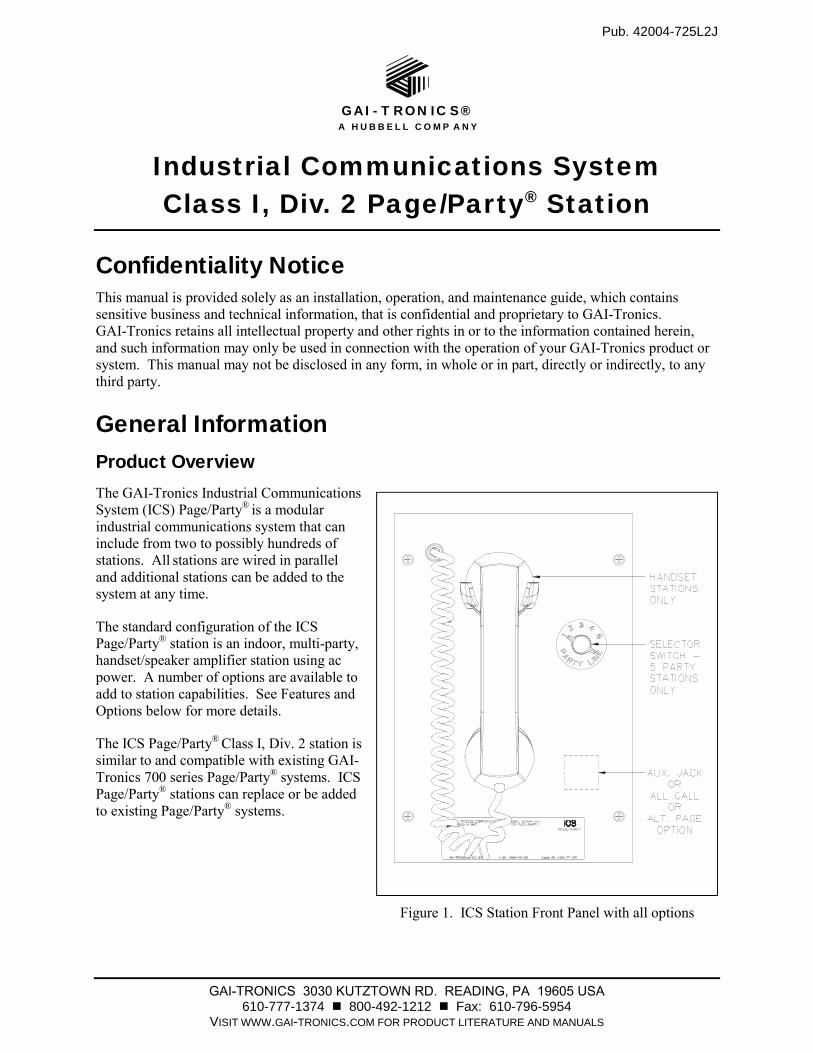
General Information Product Overview The GAI-Tronics Industrial Communications System (ICS) Page/Party®
is a modular industrial communications system that can include from two to possibly hundreds of stations. All stations are wired in parallel and additional stations can be added to the system at any time.
The standard configuration of the ICS Page/Party® station is an indoor, multi-party, handset/speaker amplifier station using ac power. A number of options are available to add to station capabilities. See Features and Options below for more details.
The ICS Page/Party® Class I, Div. 2 station is
similar to and compatible with existing GAI-Tronics 700 series Page/Party® systems. ICS Page/Party® stations can replace or be added to existing Page/Party® systems.
Figure 1. ICS Station Front Panel with all options
Pub. 42004-725L2J ICS Class I, Div. 2 Page/Party
® Station Page 2 of 34
P:\Standard IOMs - Current Release\42004 Instr. Manuals\42004-725L2J.docx 07/16
Features
Provides one-way page announcements over system speakers
Includes a high efficiency (>80%) Class D paging amplifier to provide up to 30 watts of speaker
output
Provides full-duplex party line communication
Includes universal ac power supply with power factor correction
Field upgradeable options
Durable, high visibility safety orange powder coat finish on indoor stations
Options
Single party line operation
Speaker amplifier only (no handset)
Alternate page destination
Emergency party line (EPL)
Weatherproof and desktop stations
Auxiliary jack for headset operation
Hazardous area approvals
PVC or Hytrel handset cords in 6-, 15-, or 25-foot lengths
Conformal coating for PCBA
24 V dc power
Volume Level Control (VLC) technology for alternate page volume
SmartSeries technology featuring Ambient Level Sensing (ALS) and available remote monitoring
Remote Terminal Unit (RTU) operation
70V/100V speaker output
All Call
RF hookswitch
Pub. 42004-725L2J ICS Class I, Div. 2 Page/Party
® Station Page 3 of 34
P:\Standard IOMs - Current Release\42004 Instr. Manuals\42004-725L2J.docx 07/16
Installation
Important Safety Instructions
This equipment is suitable for use in Class I, Division 2, Groups A, B, C and D, Class II Division 2,
Groups F, and G, Class III OR non-hazardous locations only. Combinations of equipment in your system
are subject to investigation by the local Authority Having Jurisdiction at the time of installation.
Read, follow, and retain instructions – All safety and operating instructions should be read and followed
before operating the unit. Retain instructions for future reference.
Heed warnings – Adhere to all warnings on the unit and in the operating instructions.
Attachments – Attachments not recommended by the product manufacturer should not be used, as they
may cause hazards. Maximum system cable length not to exceed two miles.
Servicing – Do not attempt to service this unit by yourself. Opening or removing covers may expose you
to dangerous voltage or other hazards. Refer all servicing to qualified service personnel.
This permanently connected apparatus must have a UL Listed 15-amp circuit breaker incorporated in the
electrical installation of the building.
WARNING – EXPLOSION HAZARD – Do not disconnect equipment unless power has been removed
or the area is known to be non-hazardous. Averttissement – Risque d’explosion – avant de déconnector
l’equipment, couper le courant ou s’assurer que l’emplacement est désigné non dangereux.
USA and Canada Consult the National Electrical Code (NFPA 70), Canadian Standards Association
(CSA 22.1), and local codes for specific requirements regarding your installation. Class 2 circuit wiring
must be performed in accordance with NEC 725.55.
WARNING In 24 V dc systems: Under NO condition should this equipment be operated
from a battery charger without the batteries connected.
In 24 V dc systems, most chargers have an unloaded output of 35 to 45 volts that can quickly damage the
equipment designed for nominal 24 volts. The maximum battery voltage should never exceed the
maximum specified input voltage.
Pub. 42004-725L2J ICS Class I, Div. 2 Page/Party
® Station Page 4 of 34
P:\Standard IOMs - Current Release\42004 Instr. Manuals\42004-725L2J.docx 07/16
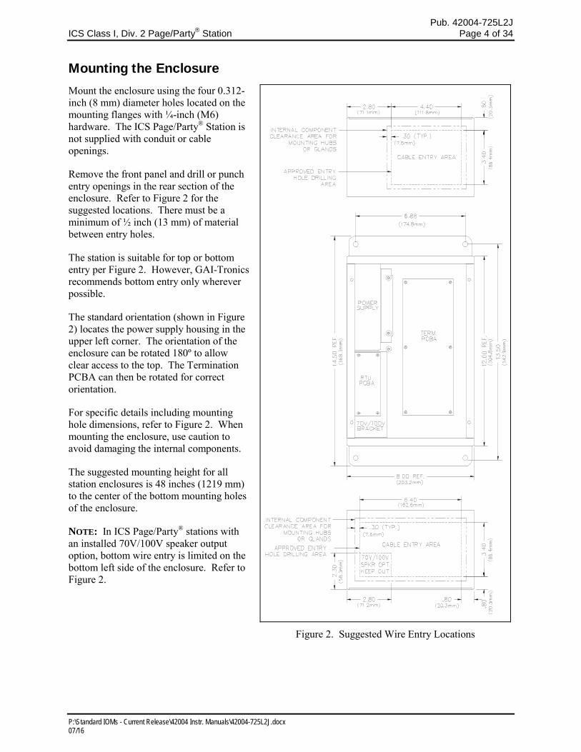
Mounting the Enclosure Mount the enclosure using the four 0.312-inch (8 mm) diameter holes located on the mounting flanges with ¼-inch (M6) hardware. The ICS Page/Party® Station is not supplied with conduit or cable openings.
Remove the front panel and drill or punch entry openings in the rear section of the enclosure. Refer to Figure 2 for the suggested locations. There must be a minimum of ½ inch (13 mm) of material between entry holes.
The station is suitable for top or bottom entry per Figure 2. However, GAI-Tronics recommends bottom entry only wherever possible.
The standard orientation (shown in Figure 2) locates the power supply housing in the upper left corner. The orientation of the enclosure can be rotated 180º to allow clear access to the top. The Termination PCBA can then be rotated for correct orientation.
For specific details including mounting hole dimensions, refer to Figure 2. When mounting the enclosure, use caution to avoid damaging the internal components.
The suggested mounting height for all station enclosures is 48 inches (1219 mm) to the center of the bottom mounting holes of the enclosure.
NOTE: In ICS Page/Party® stations with an installed 70V/100V speaker output option, bottom wire entry is limited on the bottom left side of the enclosure. Refer to Figure 2.
Figure 2. Suggested Wire Entry Locations
Pub. 42004-725L2J ICS Class I, Div. 2 Page/Party
® Station Page 5 of 34
P:\Standard IOMs - Current Release\42004 Instr. Manuals\42004-725L2J.docx 07/16
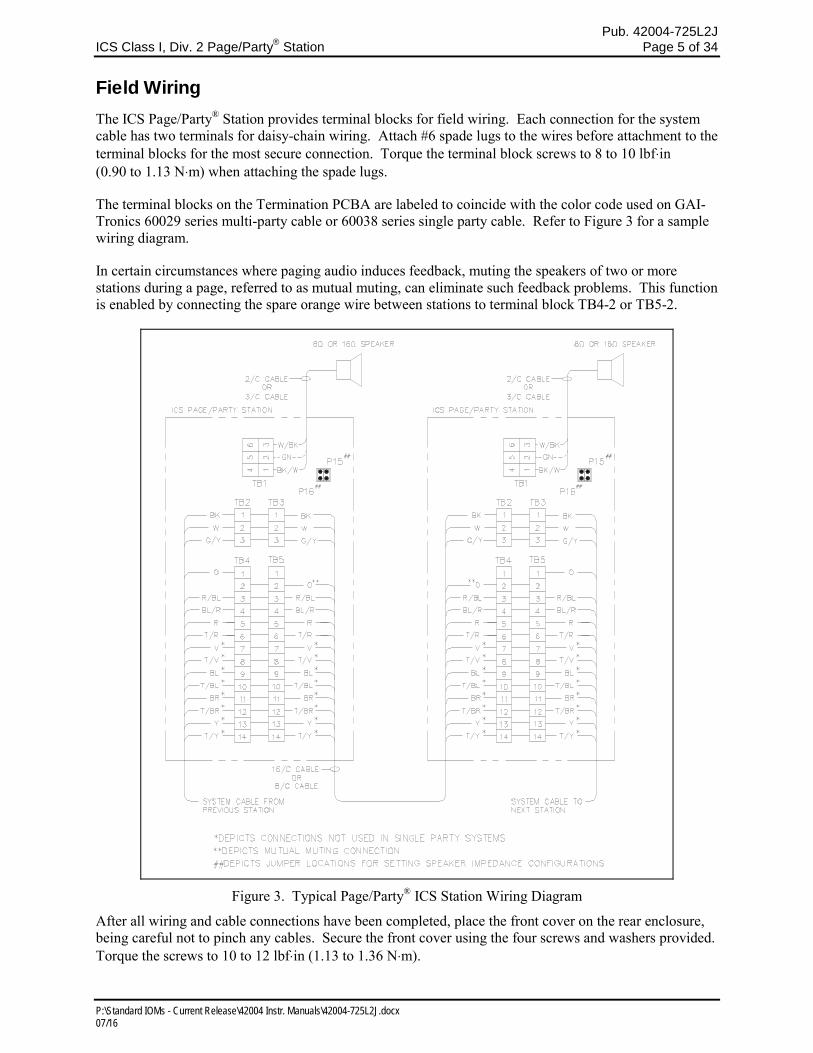
Field Wiring The ICS Page/Party® Station provides terminal blocks for field wiring. Each connection for the system cable has two terminals for daisy-chain wiring. Attach #6 spade lugs to the wires before attachment to the terminal blocks for the most secure connection. Torque the terminal block screws to 8 to 10 lbf⋅in (0.90 to 1.13 N⋅m) when attaching the spade lugs.
The terminal blocks on the Termination PCBA are labeled to coincide with the color code used on GAI-Tronics 60029 series multi-party cable or 60038 series single party cable. Refer to Figure 3 for a sample wiring diagram.
In certain circumstances where paging audio induces feedback, muting the speakers of two or more stations during a page, referred to as mutual muting, can eliminate such feedback problems. This function is enabled by connecting the spare orange wire between stations to terminal block TB4-2 or TB5-2.
Figure 3. Typical Page/Party® ICS Station Wiring Diagram
After all wiring and cable connections have been completed, place the front cover on the rear enclosure, being careful not to pinch any cables. Secure the front cover using the four screws and washers provided. Torque the screws to 10 to 12 lbf⋅in (1.13 to 1.36 N⋅m).
Pub. 42004-725L2J ICS Class I, Div. 2 Page/Party
® Station Page 6 of 34
P:\Standard IOMs - Current Release\42004 Instr. Manuals\42004-725L2J.docx 07/16
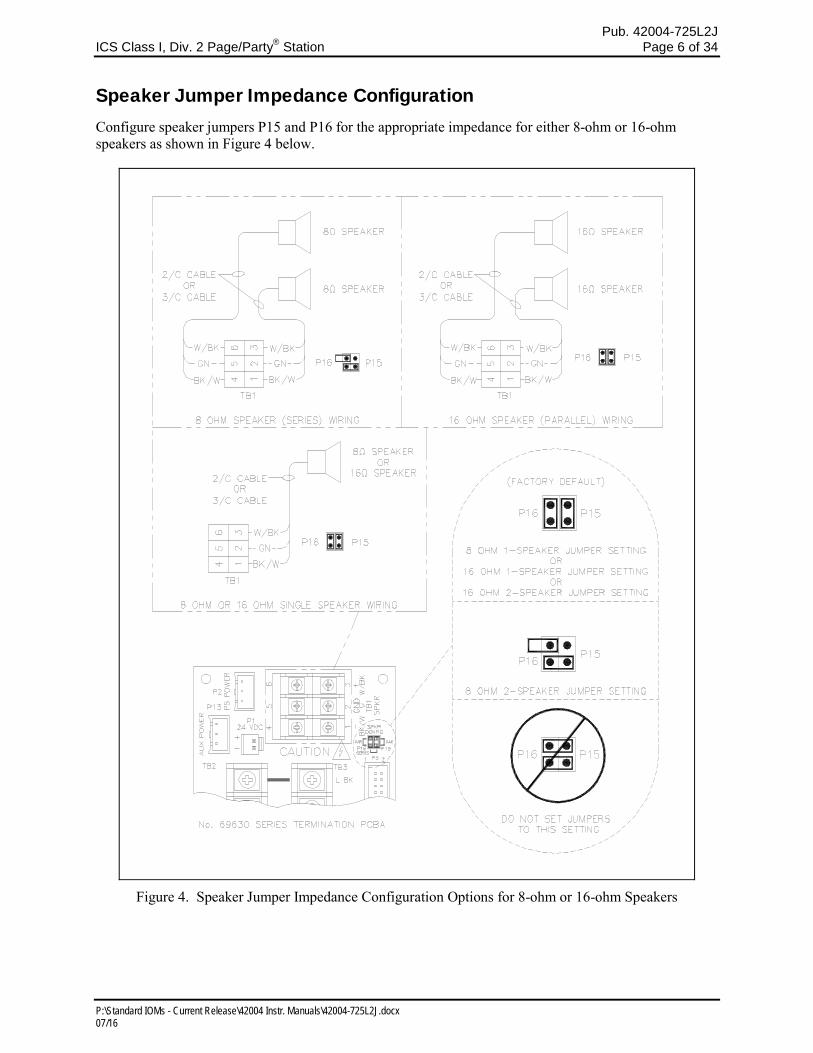
Speaker Jumper Impedance Configuration Configure speaker jumpers P15 and P16 for the appropriate impedance for either 8-ohm or 16-ohm speakers as shown in Figure 4 below.
Figure 4. Speaker Jumper Impedance Configuration Options for 8-ohm or 16-ohm Speakers
Pub. 42004-725L2J ICS Class I, Div. 2 Page/Party
® Station Page 7 of 34
P:\Standard IOMs - Current Release\42004 Instr. Manuals\42004-725L2J.docx 07/16
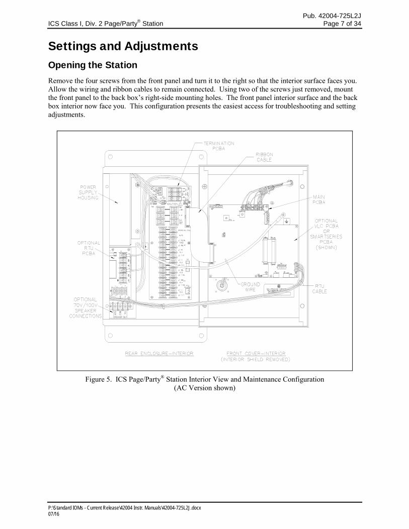
Settings and Adjustments Opening the Station Remove the four screws from the front panel and turn it to the right so that the interior surface faces you. Allow the wiring and ribbon cables to remain connected. Using two of the screws just removed, mount the front panel to the back box’s right-side mounting holes. The front panel interior surface and the back box interior now face you. This configuration presents the easiest access for troubleshooting and setting adjustments.
Figure 5. ICS Page/Party® Station Interior View and Maintenance Configuration (AC Version shown)
Pub. 42004-725L2J ICS Class I, Div. 2 Page/Party
® Station Page 8 of 34
P:\Standard IOMs - Current Release\42004 Instr. Manuals\42004-725L2J.docx 07/16
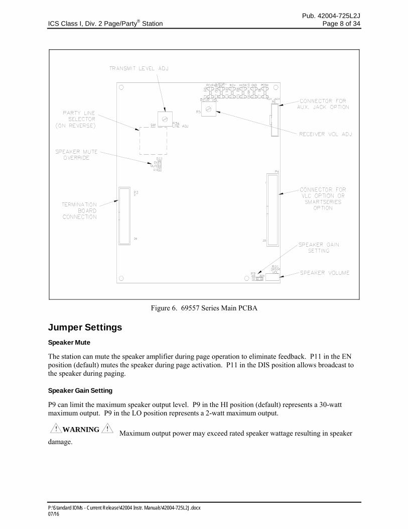
Figure 6. 69557 Series Main PCBA
Jumper Settings Speaker Mute
The station can mute the speaker amplifier during page operation to eliminate feedback. P11 in the EN position (default) mutes the speaker during page activation. P11 in the DIS position allows broadcast to the speaker during paging.
Speaker Gain Setting
P9 can limit the maximum speaker output level. P9 in the HI position (default) represents a 30-watt maximum output. P9 in the LO position represents a 2-watt maximum output.
WARNING Maximum output power may exceed rated speaker wattage resulting in speaker damage.
Pub. 42004-725L2J ICS Class I, Div. 2 Page/Party
® Station Page 9 of 34
P:\Standard IOMs - Current Release\42004 Instr. Manuals\42004-725L2J.docx 07/16
Level Adjustments
Transmit Level
The Transmit Level potentiometer, R34, adjusts the signal level from the handset or optional auxiliary
headset microphone to the page or party lines.
Receiver Volume
The Receiver Volume potentiometer, R5, adjusts the signal level to the handset receiver from the page or
party lines. It does not adjust the signal level to the optional auxiliary headset.
Speaker Volume
The Speaker Volume potentiometer, R91, adjusts the signal level to the speaker from the page line. The
default setting is 4 watts for an 8-ohm speaker and 2 watts for a 16-ohm speaker.
Warning – Maximum output power may exceed rated speaker wattage resulting in speaker damage.
Attach the Front Panel
After all adjustments have been completed, place the front cover on the rear enclosure, being careful not
to pinch any cables. Secure the front cover using the four screws and washers provided. Torque the
screws to 10 to 12 lbfin (1.13 to 1.36 Nm).
Operation
For paging and subsequent party line conversation, the station operator lifts the handset or connects the
optional headset, selects a free party line using the five-position rotary selector switch (if equipped), and
presses the handset pressbar or headset page switch. The station operator pages the desired individual and
designates the party line on which that individual should respond. The individual then responds by
approaching the nearest ICS Page/Party® station, selecting the appropriate party line and lifting the
handset or connecting a headset. Full-duplex communication can then be held on the party line without
broadcasting over the speakers. After the conversation is complete, all parties should place the handset
back on hook or disconnect the headset.
NOTES:
1. For stations with an auxiliary jack, the Model 10401-201 Headset and 10416-103 Extension Cord
allows the user to be hands-free and mobile while maintaining communication. When connected, the
handset microphone is disabled.
2. The ICS Page/Party® station incorporates a noise-canceling microphone to reduce transmitted
ambient noise. This requires the user to place the microphone as close as possible to their mouth.
Pub. 42004-725L2J ICS Class I, Div. 2 Page/Party
® Station Page 10 of 34
P:\Standard IOMs - Current Release\42004 Instr. Manuals\42004-725L2J.docx 07/16
Options The ICS Page/Party® Station options can be factory installed or field installed in some cases. The field installable options include ICS SmartSeries, VLC, and RTU.
ICS SmartSeries General
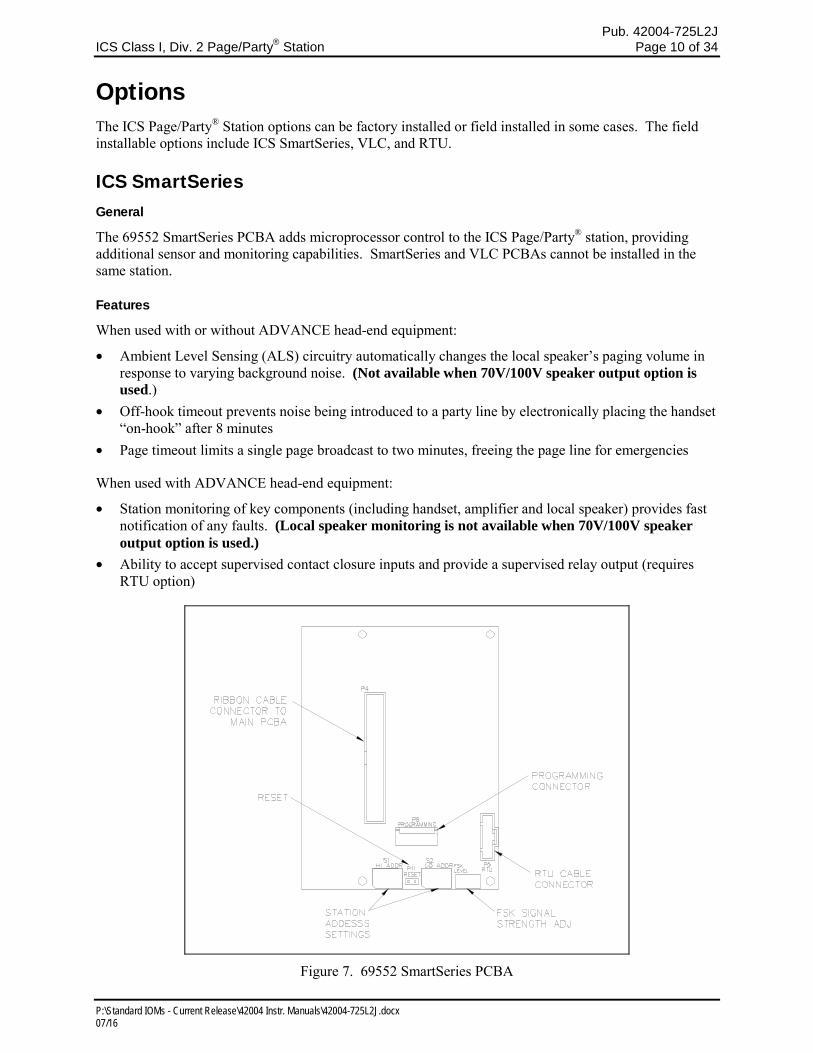
The 69552 SmartSeries PCBA adds microprocessor control to the ICS Page/Party® station, providing additional sensor and monitoring capabilities. SmartSeries and VLC PCBAs cannot be installed in the same station.
Features
When used with or without ADVANCE head-end equipment:
• Ambient Level Sensing (ALS) circuitry automatically changes the local speaker’s paging volume in response to varying background noise. (Not available when 70V/100V speaker output option is used.)
• Off-hook timeout prevents noise being introduced to a party line by electronically placing the handset “on-hook” after 8 minutes
• Page timeout limits a single page broadcast to two minutes, freeing the page line for emergencies
When used with ADVANCE head-end equipment:
• Station monitoring of key components (including handset, amplifier and local speaker) provides fast notification of any faults. (Local speaker monitoring is not available when 70V/100V speaker output option is used.)
• Ability to accept supervised contact closure inputs and provide a supervised relay output (requires RTU option)
Figure 7. 69552 SmartSeries PCBA
Pub. 42004-725L2J ICS Class I, Div. 2 Page/Party
® Station Page 11 of 34
P:\Standard IOMs - Current Release\42004 Instr. Manuals\42004-725L2J.docx 07/16
Installation and Adjustments
Opening the Station
Remove the four screws from the front panel and turn it to the right so that the interior surface faces you.
Allow the wiring and ribbon cables to remain connected. Using two of the screws just removed, mount
the front panel to the back box’s right-side mounting holes. The front panel interior surface and the back
box interior now face you. This configuration presents the easiest access for troubleshooting and setting
adjustments.
Installing the SmartSeries PCBA
Remove power from the station.
Remove all jumpers on the Main PCBA P4 connector.
Align the SmartSeries PCBA with four mounting holes to the right of the Main PCBA with the edge of
the SmartSeries board under the Main PCBA. Secure the SmartSeries PCBA with the four screws
provided.
Install the provided 34-pin ribbon cable from P4 of Main PCBA to P4 of SmartSeries PCBA.
Reapply power to the station.
Setting the Address
For the SmartSeries option to function properly, each station in an ADVANCE system zone must be
given a unique address using the hexadecimal switches, S1 (Hi Address) and S2 (Lo Address). Each
switch contains 16 settings, labeled 0–F. A small arrow on each switch indicates the setting.
The station address is determined by the high address setting followed by the low address setting. For
example, to assign an address of 05, the high station address is set to 0 and the low address is set to 5.
Valid address settings are 05 to FE. Record the address assigned for each station in the system for your
records. If the SmartSeries PCBA is installed in a system without an ADVANCE head end, set the
address to 04 (default).
ALS Minimum Level
The ALS minimum level is the lowest speaker output level that the station will maintain. To set the ALS
minimum level, turn R91 fully counterclockwise. Listen for a single beep from the speaker indicating the
speaker amplifier is in the Minimum Level Adjustment mode. If the page line is in use immediately after
the beep tone, the page signal should be used to make the minimum level adjustment. If the page line is
inactive following the beep tone, a continuous tone is activated to make the minimum level adjustment.
After the tone is activated, all page line activity is ignored until completion of the adjustment.
This test tone is used as a reference to adjust the speaker amplifier output level to the desired volume.
Adjust R91 to the desired output. The test tone automatically shuts off 5 seconds after the last
adjustment. The factory default setting for minimum level is 4.0 watts nominal into an 8-ohm load.
Pub. 42004-725L2J ICS Class I, Div. 2 Page/Party
® Station Page 12 of 34
P:\Standard IOMs - Current Release\42004 Instr. Manuals\42004-725L2J.docx 07/16
ALS Offset Level
The ALS offset level allows the output of the speaker amplifier to maintain a set difference or “offset”
between the ambient noise level and the speaker output level. To set the ALS offset level, turn R91 fully
clockwise and listen for the two beep tones indicating that the station is in the Offset Adjustment mode.
If the page line is in use immediately after the two beep tones are heard, the page signal should be used to
make the offset level adjustment. If the page line is inactive immediately following the beep tones, a
continuous tone is activated to make the offset level adjustment. After the tone is activated, all page line
activity is ignored until completion of the adjustment. Adjust R91 to the desired offset level.
NOTE: This adjustment should be made under maximum ambient noise level. The ALS offset level must
always be set higher than the ALS minimum level setting.
SmartSeries VLC Level
When activated, the VLC overrides the ALS minimum level setting allowing the speaker volume to
change to a preset level during an emergency page. To adjust the VLC Level, force the station into the
VLC mode by having someone execute a page from a station programmed by the MCU to activate the
VLC function. During the page, turn the R91 control fully counterclockwise, and listen for two beep
tones through the page speaker indicating the VLC Adjustment mode has been activated. After the two
beep tones, turn the R91 control to the desired speaker level using the live paging signal to adjust the
level. The station automatically exits the VLC Adjustment mode and reverts to normal operation 5
seconds after the last pot adjustment.
NOTE: The system must be equipped with an ADVANCE head end to activate the VLC function.
Speaker Impedance Supervision
When this feature is configured, the station will supervise the speaker line for changes in the speaker line
impedance. To perform this function the station must be calibrated for the impedance of the speaker(s)
attached. If the station has never been previously calibrated, the station will report a speaker fault within
15 minutes of being configured for this feature. The station may be calibrated either “locally” at the
station or “remotely” by a system command from the ADVANCE head end. See the ADVANCE System
Programming Manual for details of “remote” calibration.
To perform a “local” calibration, first ensure that the station is configured for speaker impedance
supervision. Next, set the station's address to 0x02. Wait until you hear a single-beep tone at the attached
speaker. This should occur within 20 seconds. This tone indicates that a successful calibration was
performed.
If instead a double-beep tone is heard, this indicates that the station attempted to calibrate but was
unsuccessful (the attached impedance is out-of-range). If a tone is not heard, the station may not be
configured for speaker impedance supervision or there is an open connection to the speaker.
After hearing the single beep tone, set the address back to its original value to resume normal station
operation with the new calibration value.
NOTE: If this feature is used, then jumper P9 of the Main PCBA must be in the HI (default) position.

Pub. 42004-725L2J ICS Class I, Div. 2 Page/Party
® Station Page 13 of 34
P:\Standard IOMs - Current Release\42004 Instr. Manuals\42004-725L2J.docx 07/16
FSK Signal Gain
The FSK Signal Gain, R13, adjusts the FSK transmit signal strength. It is set at the factory and should
not be adjusted by the installer.
Attaching the Front Panel
After all adjustments have been completed, place the front cover on the rear enclosure, being careful not
to pinch any cables. Secure the front cover using the four screws and washers provided. Torque the
screws to 10 to 12 lbfin (1.13 to 1.36 Nm).
Operation
Paging with ADVANCE Head End
Paging and party line operation with the ICS SmartSeries option is similar to standard station operation.
The main differences are that when the handset pressbar or the headset page switch is pressed, a steady
“wait” tone will be heard in the handset/headset earpiece. When the “wait” tone ends, a pre-
announcement tone, if programmed, will sound, and the operator may place their page. If the system is
busy and the page is denied, the user will hear a busy tone in the handset/headset earpiece.
Paging without ADVANCE Head End
Paging and party line operation will be similar to standard station operation.
Station Time-out Features
The ICS SmartSeries option supports a page duration limit that sets the maximum duration of each page.
If the page is still active when the page duration limit is reached, the page will be terminated. When used
without an ADVANCE head end, the page duration limit is fixed at 2 minutes.
The ICS SmartSeries option supports an off-hook limit that sets the maximum duration that the station
may be kept off hook. If the off-hook limit is reached, the station will be placed electrically on hook. To
reset the timeout condition, the handset must be physically placed on hook momentarily. When used
without an ADVANCE head end, the off-hook limit is fixed at 8 minutes.
Pub. 42004-725L2J ICS Class I, Div. 2 Page/Party
® Station Page 14 of 34
P:\Standard IOMs - Current Release\42004 Instr. Manuals\42004-725L2J.docx 07/16
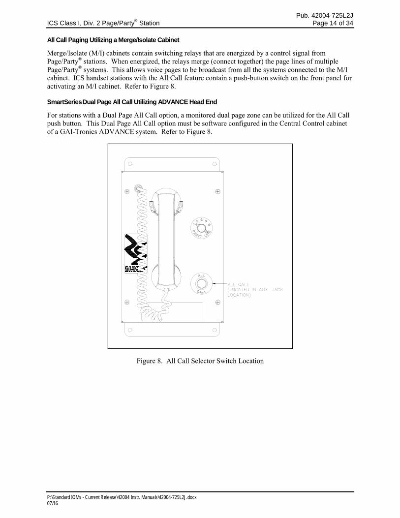
All Call Paging Utilizing a Merge/Isolate Cabinet
Merge/Isolate (M/I) cabinets contain switching relays that are energized by a control signal from Page/Party® stations. When energized, the relays merge (connect together) the page lines of multiple Page/Party® systems. This allows voice pages to be broadcast from all the systems connected to the M/I cabinet. ICS handset stations with the All Call feature contain a push-button switch on the front panel for activating an M/I cabinet. Refer to Figure 8.
SmartSeries Dual Page All Call Utilizing ADVANCE Head End
For stations with a Dual Page All Call option, a monitored dual page zone can be utilized for the All Call push button. This Dual Page All Call option must be software configured in the Central Control cabinet of a GAI-Tronics ADVANCE system. Refer to Figure 8.
Figure 8. All Call Selector Switch Location
Pub. 42004-725L2J ICS Class I, Div. 2 Page/Party
® Station Page 15 of 34
P:\Standard IOMs - Current Release\42004 Instr. Manuals\42004-725L2J.docx 07/16
Emergency Party Line (EPL)
When connected to an ADVANCE control cabinet, the EPL option enables the ICS SmartSeries Station to automatically report the following information when the handset is taken off-hook.
• Zone number
• Station address
• Party line (1 or 2)
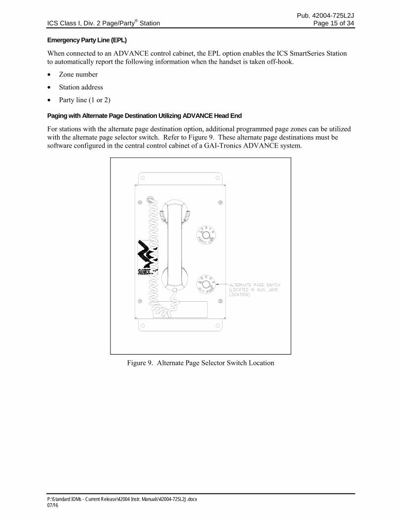
Paging with Alternate Page Destination Utilizing ADVANCE Head End
For stations with the alternate page destination option, additional programmed page zones can be utilized with the alternate page selector switch. Refer to Figure 9. These alternate page destinations must be software configured in the central control cabinet of a GAI-Tronics ADVANCE system.
Figure 9. Alternate Page Selector Switch Location
Pub. 42004-725L2J ICS Class I, Div. 2 Page/Party
® Station Page 16 of 34
P:\Standard IOMs - Current Release\42004 Instr. Manuals\42004-725L2J.docx 07/16
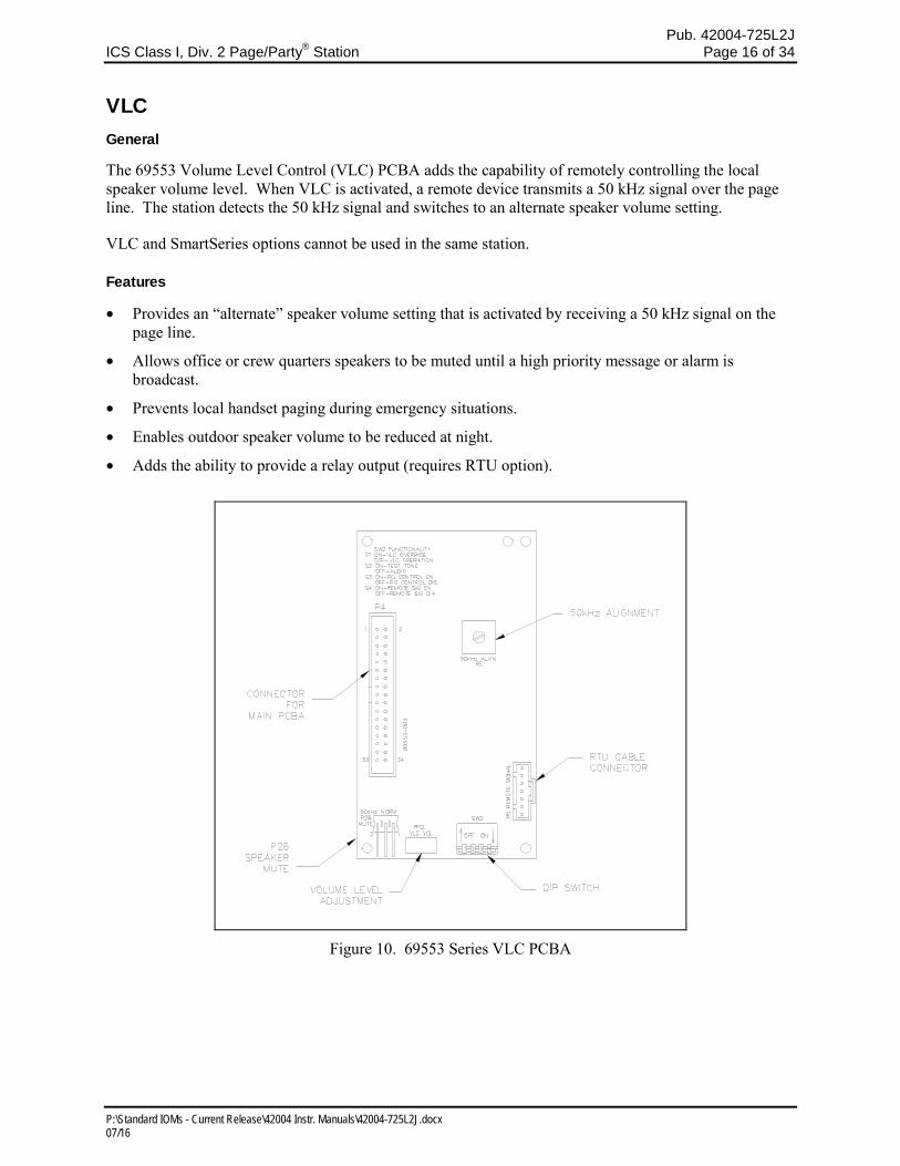
VLC General
The 69553 Volume Level Control (VLC) PCBA adds the capability of remotely controlling the local speaker volume level. When VLC is activated, a remote device transmits a 50 kHz signal over the page line. The station detects the 50 kHz signal and switches to an alternate speaker volume setting.
VLC and SmartSeries options cannot be used in the same station.
Features
• Provides an “alternate” speaker volume setting that is activated by receiving a 50 kHz signal on the page line.
• Allows office or crew quarters speakers to be muted until a high priority message or alarm is broadcast.
• Prevents local handset paging during emergency situations.
• Enables outdoor speaker volume to be reduced at night.
• Adds the ability to provide a relay output (requires RTU option).
Figure 10. 69553 Series VLC PCBA
Pub. 42004-725L2J ICS Class I, Div. 2 Page/Party
® Station Page 17 of 34
P:\Standard IOMs - Current Release\42004 Instr. Manuals\42004-725L2J.docx 07/16
Installation and Adjustments
Opening the Station
Remove the four screws from the front panel and turn it to the right so that the interior surface faces you.
Allow the wiring and ribbon cables to remain connected. Using two of the screws just removed, mount
the front panel to the back box’s right-side mounting holes. The front panel interior surface and the back
box interior now face you. This configuration presents the easiest access for troubleshooting and setting
adjustments.
Installing the VLC PCBA
Remove power from the station.
Remove all jumpers on the Main PCBA P4 connector.
Align the VLC PCBA with four mounting holes to the right of the Main PCBA. Secure the VLC PCBA
with the four screws provided. Install the provided 34-pin ribbon cable from P4 of Main PCBA to P4 of
VLC PCBA.
Reapply power to the station.
50 kHz Alignment
The 50 kHz alignment, R5, adjusts the receiver’s frequency for VLC operation. It is set at the factory and
should not be adjusted by the installer.
Speaker Mute
P26 allows for the installer to mute the speaker audio during VLC operation or normal operation. In the
“50kHz” position, the audio is muted during a VLC broadcast. In the “NORM” position, the audio is
muted during normal operation. To operate the unit without the muting feature, remove P26.
Audio Alignment
To set the normal speaker output level, set DIP switch SW2-1 to the “off” position. Set SW2-2 to the
“on” position to enable a reference test tone. Adjust R91 on the Main PCBA (refer to Figure 6 for
location) to the desired audio level. To mute the audio, turn R91 fully counterclockwise and put P26,
MUTE, in the “NORM” position.
NOTE: If LED2 on the VLC PCBA is on, indicating the system VLC tone is present, this adjustment
cannot be made.
To set the VLC controlled speaker output level, set SW2-1 to the “on” position. Set SW2-2 to the “on”
position to enable a reference test tone. Adjust R12 on the VLC PCBA to the desired audio level. To
mute the audio, turn R91 fully counterclockwise and put P26, MUTE, in the “50KHz” position.
Set SW2-1 and SW2-2 to the “off” position to return to normal system operation.
Page Disable Control
To disable local paging when the system VLC tone is present, set SW2-3 to the “on” position.
Remote Output Switching (Available with RTU Only)
To activate the RTU relay when the system VLC tone is present, set SW2-4 to the “on” position.
Attaching the Front Panel
After all adjustments have been completed, place the front cover on the rear enclosure, being careful not
to pinch any cables. Secure the front cover using the four screws and washers provided. Torque the
screws to 10 to 12 lbfin (1.13 to 1.36 Nm).
Pub. 42004-725L2J ICS Class I, Div. 2 Page/Party
® Station Page 18 of 34
P:\Standard IOMs - Current Release\42004 Instr. Manuals\42004-725L2J.docx 07/16
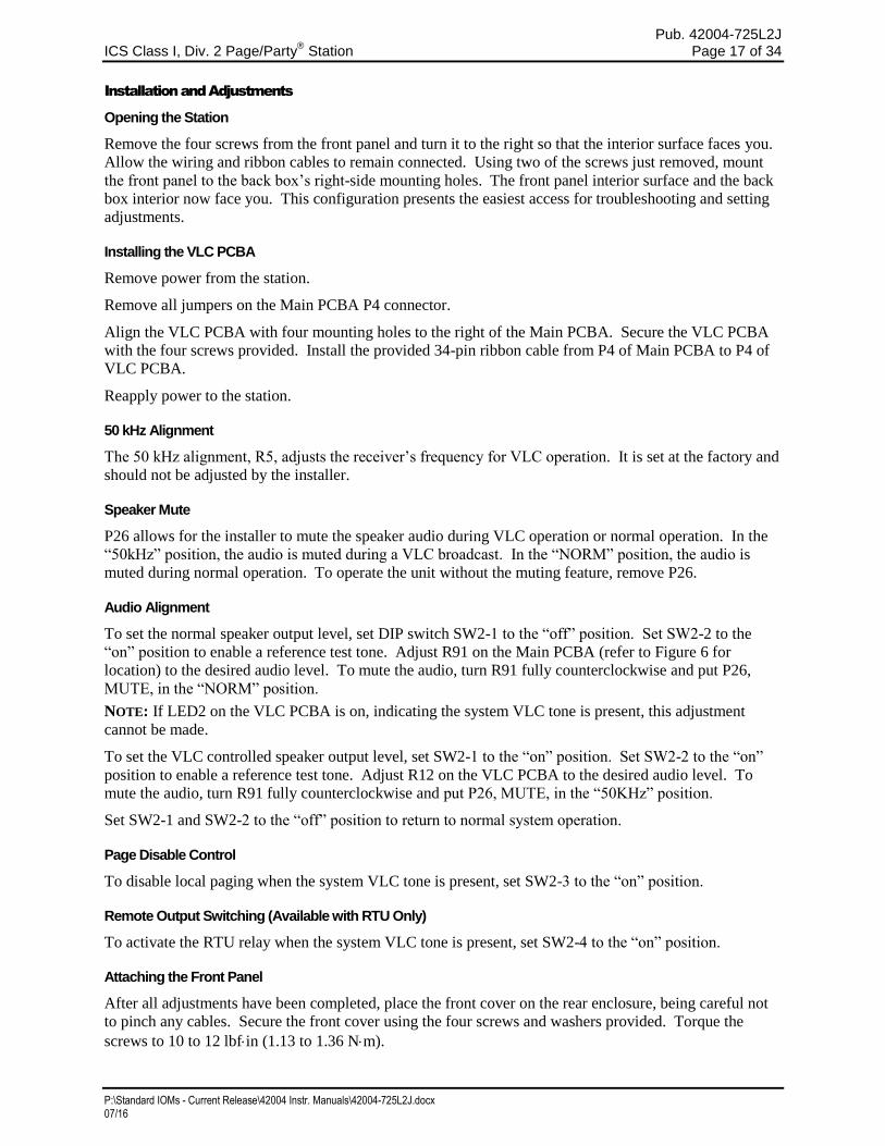
RTU General
The 69627 Remote Terminal Unit (RTU) PCBA adds remotely controlled dry relay contacts to an ICS Page/Party® station equipped with either a VLC PCBA or a SmartSeries PCBA in conjunction with an ADVANCE head end. When used with the SmartSeries PCBA in conjunction with ADVANCE head end, two supervised inputs are also available.
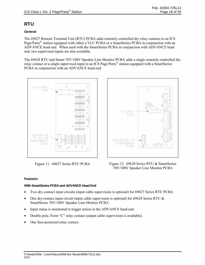
The 69628 RTU and Smart 70V/100V Speaker Line Monitor PCBA adds a single remotely controlled dry relay contact or a single supervised input to an ICS Page/Party® station equipped with a SmartSeries PCBA in conjunction with an ADVANCE head end.
Figure 11. 69627 Series RTU PCBA
Figure 12. 69628 Series RTU & SmartSeries 70V/100V Speaker Line Monitor PCBA
Features
With SmartSeries PCBA and ADVANCE Head End
• Two dry-contact input circuits (input cable supervision is optional) for 69627 Series RTU PCBA
• One dry-contact input circuit (input cable supervision is optional) for 69628 Series RTU & SmartSeries 70V/100V Speaker Line Monitor PCBA
• Input status is monitored to trigger action in the ADVANCE head end.
• Double pole, Form “C” relay contact (output cable supervision is available).
• One fuse-protected relay contact.
Pub. 42004-725L2J ICS Class I, Div. 2 Page/Party
® Station Page 19 of 34
P:\Standard IOMs - Current Release\42004 Instr. Manuals\42004-725L2J.docx 07/16
With VLC PCBA
• Double-pole, Form “C” relay contacts.
• One fuse-protected relay contact.
With SmartSeries PCBA and Dual Page All Call with ADVANCE Head End
• One dry-contact input circuit
• Input status is monitored to trigger action in the ADVANCE head end.
• Double pole, Form “C” relay contact (output cable supervision is available).
• One fuse-protected relay contact.
Installation
Opening the Station
Remove the four screws from the front panel and turn it to the right so that the interior surface faces you. Allow the wiring and ribbon cables to remain connected. Using two of the screws just removed, mount the front panel to the back box’s right-side mounting holes. The front panel interior surface and the back box interior now face you. This configuration presents the easiest access for troubleshooting and setting adjustments.
Installing the RTU PCBA
Remove power from the station.
Install the four provided standoffs onto the four studs located adjacent to the power supply.
Align the RTU PCBA with the four standoffs with TB7 oriented toward the Termination PCBA. See Figure 5. Secure the RTU PCBA with the four screws provided.
Install the provided 6-conductor harness from P5 of the SmartSeries or VLC PCBA to P5 of RTU PCBA.
Reapply power to the station.
Pub. 42004-725L2J ICS Class I, Div. 2 Page/Party
® Station Page 20 of 34
P:\Standard IOMs - Current Release\42004 Instr. Manuals\42004-725L2J.docx 07/16
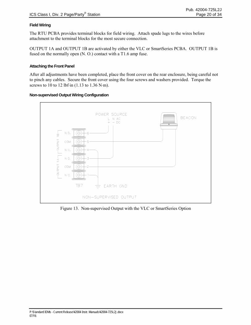
Field Wiring
The RTU PCBA provides terminal blocks for field wiring. Attach spade lugs to the wires before attachment to the terminal blocks for the most secure connection.
OUTPUT 1A and OUTPUT 1B are activated by either the VLC or SmartSeries PCBA. OUTPUT 1B is fused on the normally open (N. O.) contact with a T1.6 amp fuse.
Attaching the Front Panel
After all adjustments have been completed, place the front cover on the rear enclosure, being careful not to pinch any cables. Secure the front cover using the four screws and washers provided. Torque the screws to 10 to 12 lbf⋅in (1.13 to 1.36 N⋅m).
Non-supervised Output Wiring Configuration
Figure 13. Non-supervised Output with the VLC or SmartSeries Option
Pub. 42004-725L2J ICS Class I, Div. 2 Page/Party
® Station Page 21 of 34
P:\Standard IOMs - Current Release\42004 Instr. Manuals\42004-725L2J.docx 07/16
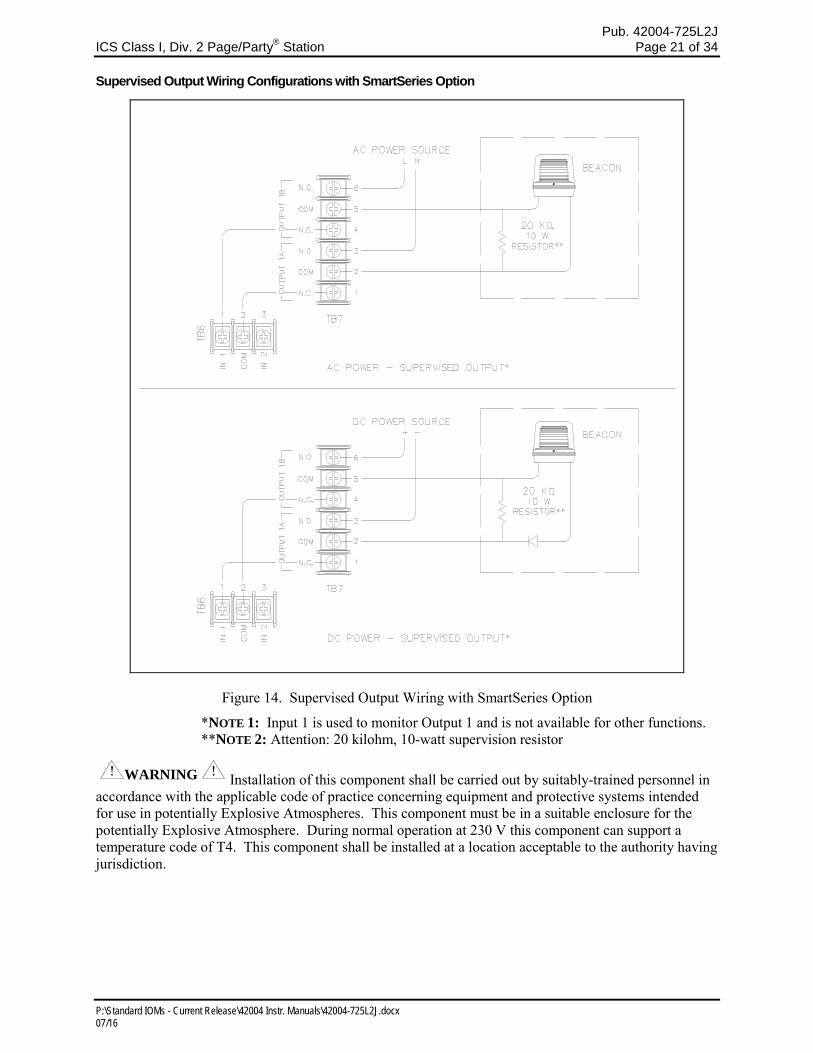
Supervised Output Wiring Configurations with SmartSeries Option
Figure 14. Supervised Output Wiring with SmartSeries Option
*NOTE 1: Input 1 is used to monitor Output 1 and is not available for other functions. **NOTE 2: Attention: 20 kilohm, 10-watt supervision resistor
WARNING Installation of this component shall be carried out by suitably-trained personnel in accordance with the applicable code of practice concerning equipment and protective systems intended for use in potentially Explosive Atmospheres. This component must be in a suitable enclosure for the potentially Explosive Atmosphere. During normal operation at 230 V this component can support a temperature code of T4. This component shall be installed at a location acceptable to the authority having jurisdiction.
Pub. 42004-725L2J ICS Class I, Div. 2 Page/Party
® Station Page 22 of 34
P:\Standard IOMs - Current Release\42004 Instr. Manuals\42004-725L2J.docx 07/16
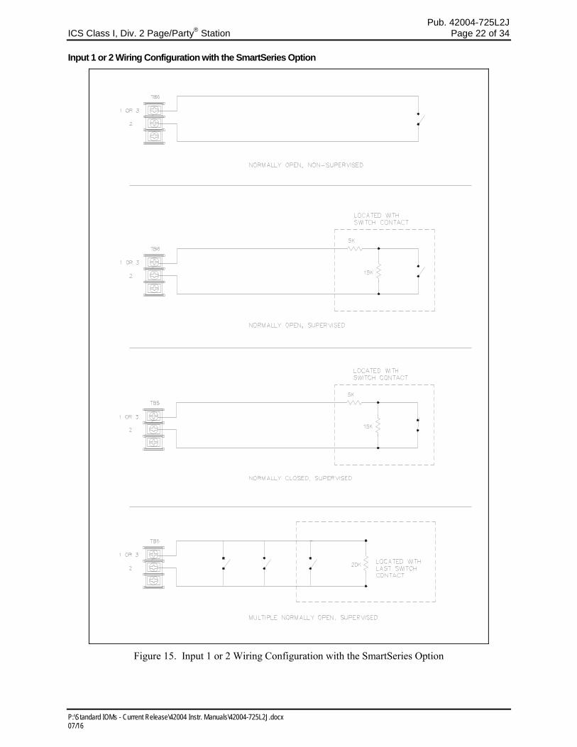
Input 1 or 2 Wiring Configuration with the SmartSeries Option
Figure 15. Input 1 or 2 Wiring Configuration with the SmartSeries Option

Pub. 42004-725L2J ICS Class I, Div. 2 Page/Party
® Station Page 23 of 34
P:\Standard IOMs - Current Release\42004 Instr. Manuals\42004-725L2J.docx 07/16
Standard Station 70V/100V Speaker Output General
The 70V/100V speaker output assembly provides the ability to connect several 70-volt or 100-volt speakers to a single ICS Page/Party® station. Speakers are wired in parallel to the station. Refer to Figure 16 below and Figure 18 on Page 24.
Field Wiring
For 100 V speakers, connect wires to the terminal block TB8 - 100V and COM. For 70 V speakers, connect wires to the terminal block TB8 - 70V and COM.
Figure 16. Standard Station 70V/100V Speaker Output Assembly
Figure 17. SmartSeries Station 70V/100V Speaker Line Monitor Assembly
Pub. 42004-725L2J ICS Class I, Div. 2 Page/Party
® Station Page 24 of 34
P:\Standard IOMs - Current Release\42004 Instr. Manuals\42004-725L2J.docx 07/16
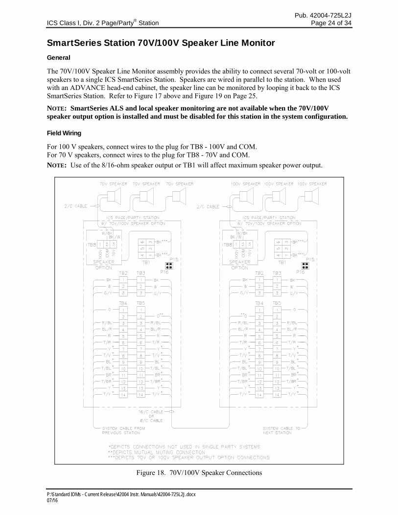
SmartSeries Station 70V/100V Speaker Line Monitor General
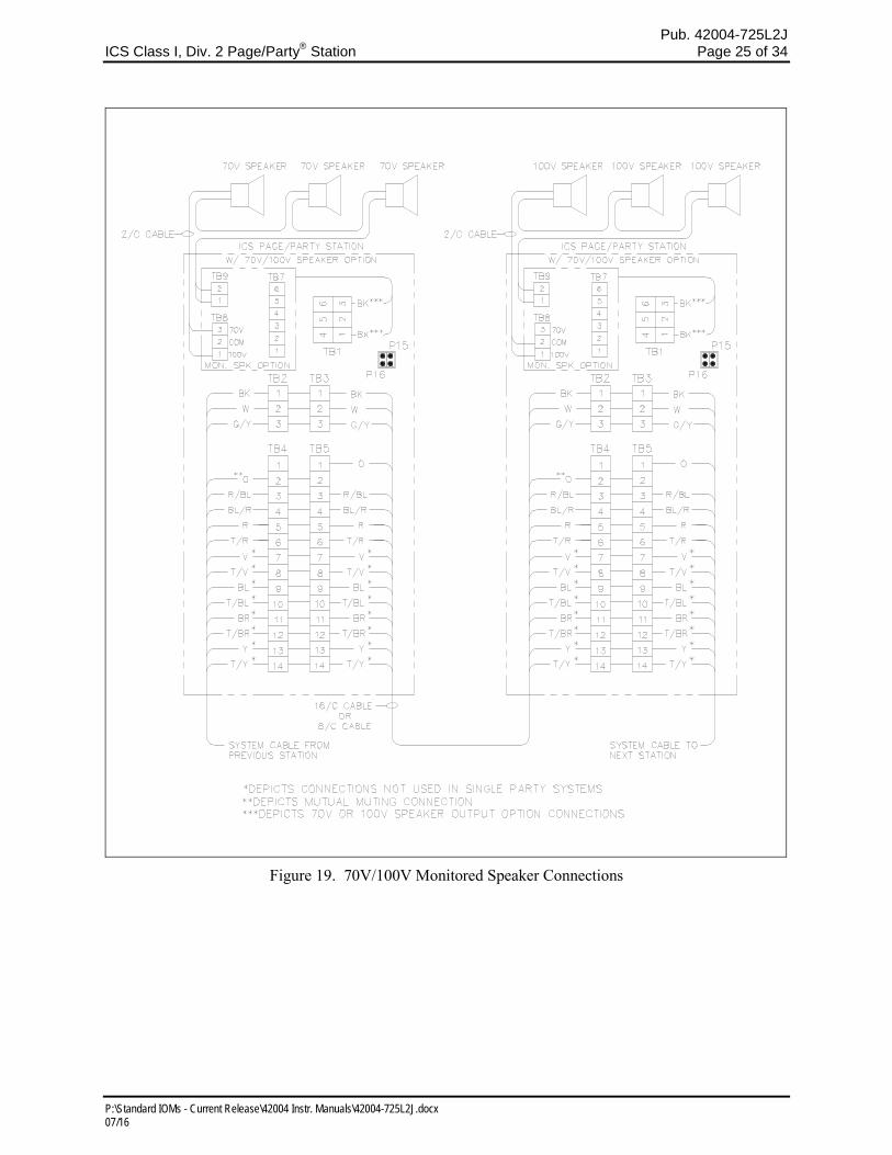
The 70V/100V Speaker Line Monitor assembly provides the ability to connect several 70-volt or 100-volt speakers to a single ICS SmartSeries Station. Speakers are wired in parallel to the station. When used with an ADVANCE head-end cabinet, the speaker line can be monitored by looping it back to the ICS SmartSeries Station. Refer to Figure 17 above and Figure 19 on Page 25.
NOTE: SmartSeries ALS and local speaker monitoring are not available when the 70V/100V speaker output option is installed and must be disabled for this station in the system configuration.
Field Wiring
For 100 V speakers, connect wires to the plug for TB8 - 100V and COM. For 70 V speakers, connect wires to the plug for TB8 - 70V and COM.
NOTE: Use of the 8/16-ohm speaker output or TB1 will affect maximum speaker power output.
Figure 18. 70V/100V Speaker Connections
Pub. 42004-725L2J ICS Class I, Div. 2 Page/Party
® Station Page 25 of 34
P:\Standard IOMs - Current Release\42004 Instr. Manuals\42004-725L2J.docx 07/16
Figure 19. 70V/100V Monitored Speaker Connections
Pub. 42004-725L2J ICS Class I, Div. 2 Page/Party
® Station Page 26 of 34
P:\Standard IOMs - Current Release\42004 Instr. Manuals\42004-725L2J.docx 07/16
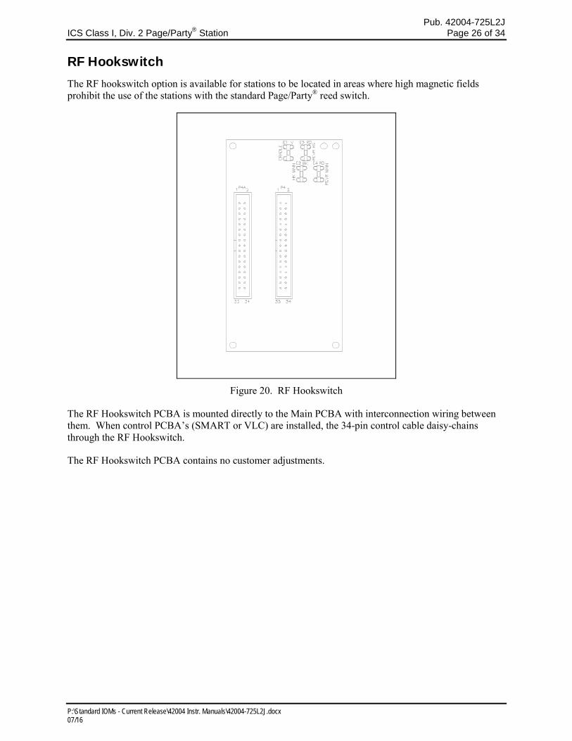
RF Hookswitch The RF hookswitch option is available for stations to be located in areas where high magnetic fields prohibit the use of the stations with the standard Page/Party® reed switch.
Figure 20. RF Hookswitch
The RF Hookswitch PCBA is mounted directly to the Main PCBA with interconnection wiring between them. When control PCBA’s (SMART or VLC) are installed, the 34-pin control cable daisy-chains through the RF Hookswitch.
The RF Hookswitch PCBA contains no customer adjustments.
Pub. 42004-725L2J ICS Class I, Div. 2 Page/Party
® Station Page 27 of 34
P:\Standard IOMs - Current Release\42004 Instr. Manuals\42004-725L2J.docx 07/16
Troubleshooting Opening the Station Remove the four screws from the front panel and turn it to the right so that the interior surface faces you. Allow the wiring and ribbon cables to remain connected. Using two of the screws just removed, mount the front panel to the back box’s right-side mounting holes. The front panel interior surface and the back box interior now face you. This configuration presents the easiest access for troubleshooting and setting adjustments.
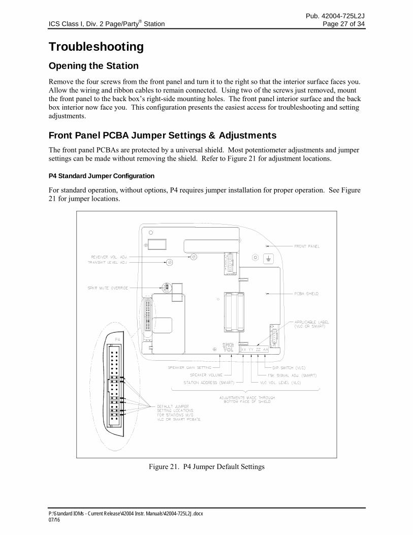
Front Panel PCBA Jumper Settings & Adjustments The front panel PCBAs are protected by a universal shield. Most potentiometer adjustments and jumper settings can be made without removing the shield. Refer to Figure 21 for adjustment locations.
P4 Standard Jumper Configuration
For standard operation, without options, P4 requires jumper installation for proper operation. See Figure 21 for jumper locations.
Figure 21. P4 Jumper Default Settings
Pub. 42004-725L2J ICS Class I, Div. 2 Page/Party
® Station Page 28 of 34
P:\Standard IOMs - Current Release\42004 Instr. Manuals\42004-725L2J.docx 07/16
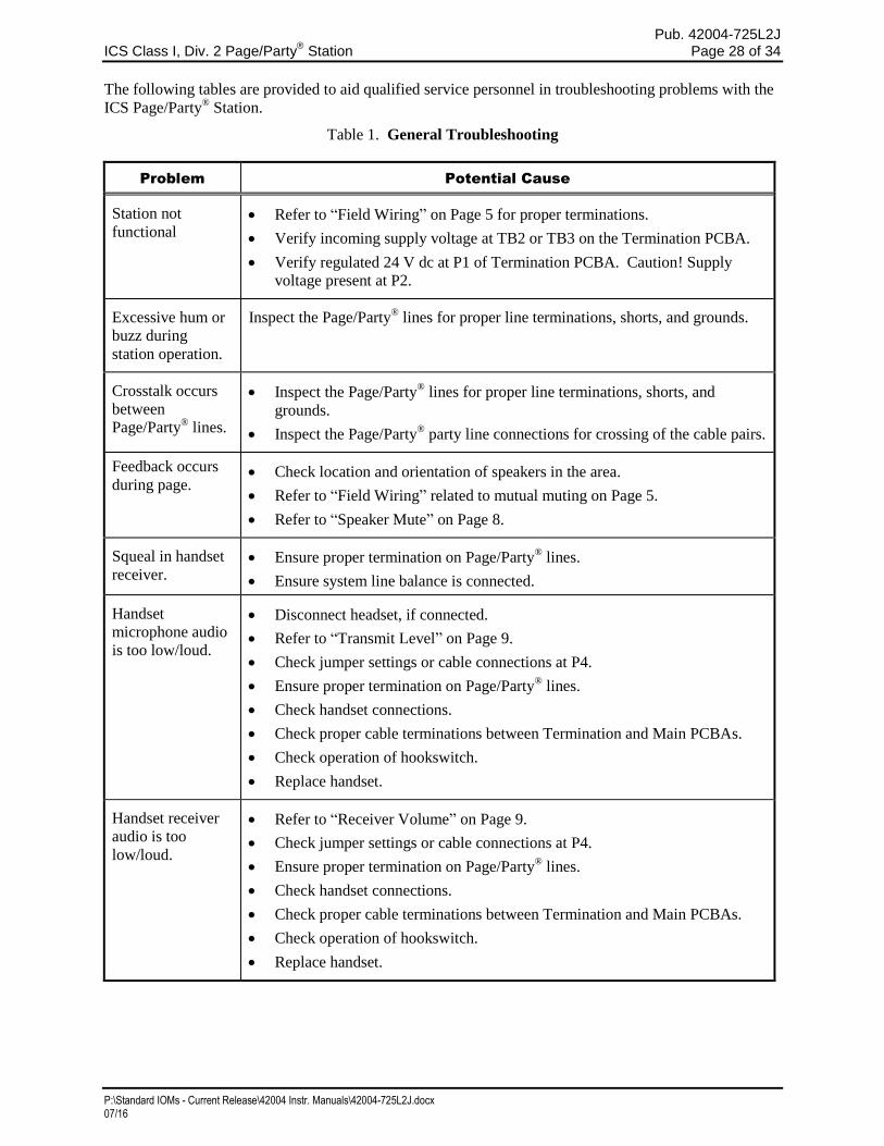
The following tables are provided to aid qualified service personnel in troubleshooting problems with the
ICS Page/Party® Station.
Table 1. General Troubleshooting
Problem Potential Cause
Station not
functional Refer to “Field Wiring” on Page 5 for proper terminations.
Verify incoming supply voltage at TB2 or TB3 on the Termination PCBA.
Verify regulated 24 V dc at P1 of Termination PCBA. Caution! Supply
voltage present at P2.
Excessive hum or
buzz during
station operation.
Inspect the Page/Party® lines for proper line terminations, shorts, and grounds.
Crosstalk occurs
between
Page/Party® lines.
Inspect the Page/Party® lines for proper line terminations, shorts, and
grounds.
Inspect the Page/Party® party line connections for crossing of the cable pairs.
Feedback occurs
during page. Check location and orientation of speakers in the area.
Refer to “Field Wiring” related to mutual muting on Page 5.
Refer to “Speaker Mute” on Page 8.
Squeal in handset
receiver. Ensure proper termination on Page/Party
® lines.
Ensure system line balance is connected.
Handset
microphone audio
is too low/loud.
Disconnect headset, if connected.
Refer to “Transmit Level” on Page 9.
Check jumper settings or cable connections at P4.
Ensure proper termination on Page/Party® lines.
Check handset connections.
Check proper cable terminations between Termination and Main PCBAs.
Check operation of hookswitch.
Replace handset.
Handset receiver
audio is too
low/loud.
Refer to “Receiver Volume” on Page 9.
Check jumper settings or cable connections at P4.
Ensure proper termination on Page/Party® lines.
Check handset connections.
Check proper cable terminations between Termination and Main PCBAs.
Check operation of hookswitch.
Replace handset.
Pub. 42004-725L2J ICS Class I, Div. 2 Page/Party
® Station Page 29 of 34
P:\Standard IOMs - Current Release\42004 Instr. Manuals\42004-725L2J.docx 07/16
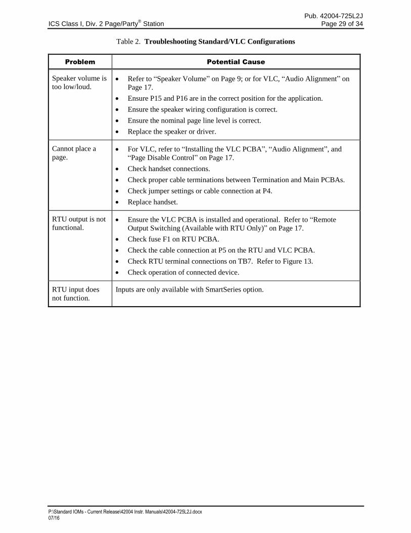
Table 2. Troubleshooting Standard/VLC Configurations
Problem Potential Cause
Speaker volume is
too low/loud. Refer to “Speaker Volume” on Page 9; or for VLC, “Audio Alignment” on
Page 17.
Ensure P15 and P16 are in the correct position for the application.
Ensure the speaker wiring configuration is correct.
Ensure the nominal page line level is correct.
Replace the speaker or driver.
Cannot place a
page. For VLC, refer to “Installing the VLC PCBA”, “Audio Alignment”, and
“Page Disable Control” on Page 17.
Check handset connections.
Check proper cable terminations between Termination and Main PCBAs.
Check jumper settings or cable connection at P4.
Replace handset.
RTU output is not
functional. Ensure the VLC PCBA is installed and operational. Refer to “Remote
Output Switching (Available with RTU Only)” on Page 17.
Check fuse F1 on RTU PCBA.
Check the cable connection at P5 on the RTU and VLC PCBA.
Check RTU terminal connections on TB7. Refer to Figure 13.
Check operation of connected device.
RTU input does
not function.
Inputs are only available with SmartSeries option.
Pub. 42004-725L2J ICS Class I, Div. 2 Page/Party
® Station Page 30 of 34
P:\Standard IOMs - Current Release\42004 Instr. Manuals\42004-725L2J.docx 07/16
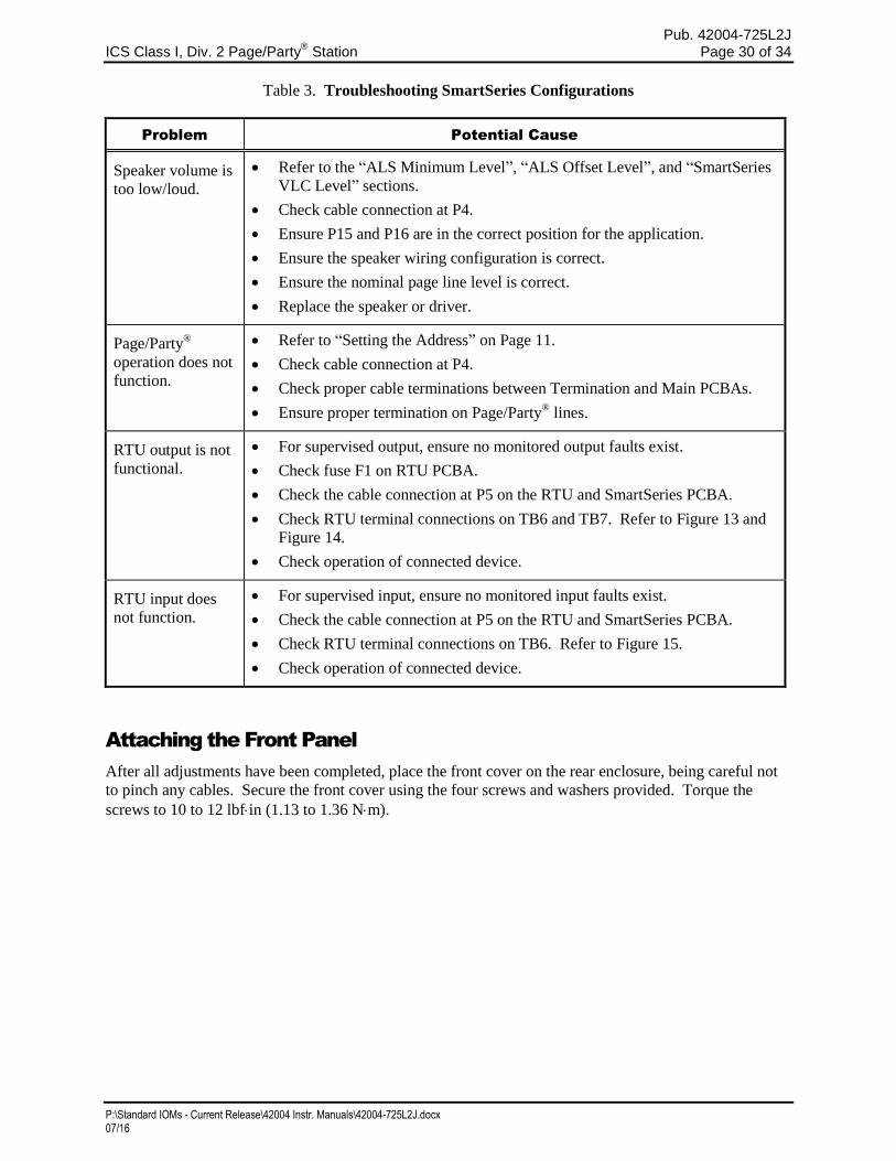
Table 3. Troubleshooting SmartSeries Configurations
Problem Potential Cause
Speaker volume is
too low/loud.
Refer to the “ALS Minimum Level”, “ALS Offset Level”, and “SmartSeries
VLC Level” sections.
Check cable connection at P4.
Ensure P15 and P16 are in the correct position for the application.
Ensure the speaker wiring configuration is correct.
Ensure the nominal page line level is correct.
Replace the speaker or driver.
Page/Party®
operation does not
function.
Refer to “Setting the Address” on Page 11.
Check cable connection at P4.
Check proper cable terminations between Termination and Main PCBAs.
Ensure proper termination on Page/Party® lines.
RTU output is not
functional.
For supervised output, ensure no monitored output faults exist.
Check fuse F1 on RTU PCBA.
Check the cable connection at P5 on the RTU and SmartSeries PCBA.
Check RTU terminal connections on TB6 and TB7. Refer to Figure 13 and
Figure 14.
Check operation of connected device.
RTU input does
not function.
For supervised input, ensure no monitored input faults exist.
Check the cable connection at P5 on the RTU and SmartSeries PCBA.
Check RTU terminal connections on TB6. Refer to Figure 15.
Check operation of connected device.
Attaching the Front Panel
After all adjustments have been completed, place the front cover on the rear enclosure, being careful not
to pinch any cables. Secure the front cover using the four screws and washers provided. Torque the
screws to 10 to 12 lbfin (1.13 to 1.36 Nm).
Pub. 42004-725L2J ICS Class I, Div. 2 Page/Party
® Station Page 31 of 34
P:\Standard IOMs - Current Release\42004 Instr. Manuals\42004-725L2J.docx 07/16
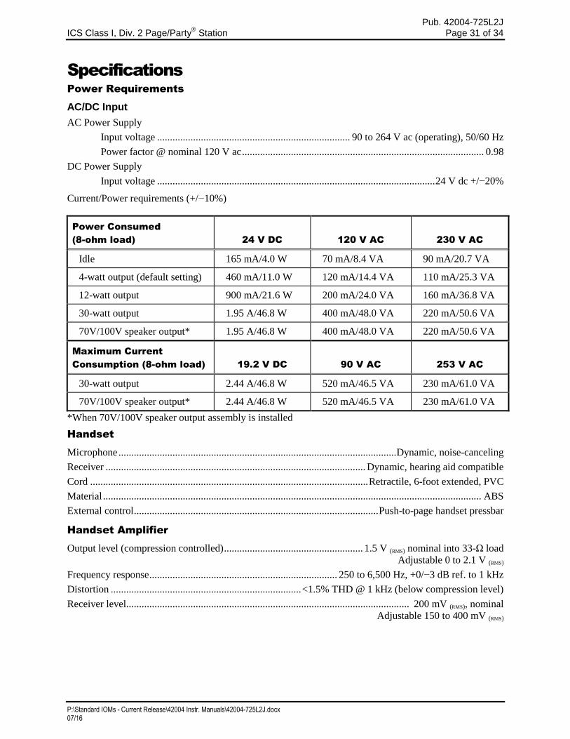
Specifications
Power Requirements
AC/DC Input
AC Power Supply
Input voltage ........................................................................... 90 to 264 V ac (operating), 50/60 Hz
Power factor @ nominal 120 V ac .............................................................................................. 0.98
DC Power Supply
Input voltage ............................................................................................................ 24 V dc +/−20%
Current/Power requirements (+/−10%)
Power Consumed
(8-ohm load) 24 V DC 120 V AC 230 V AC
Idle 165 mA/4.0 W 70 mA/8.4 VA 90 mA/20.7 VA
4-watt output (default setting) 460 mA/11.0 W 120 mA/14.4 VA 110 mA/25.3 VA
12-watt output 900 mA/21.6 W 200 mA/24.0 VA 160 mA/36.8 VA
30-watt output 1.95 A/46.8 W 400 mA/48.0 VA 220 mA/50.6 VA
70V/100V speaker output* 1.95 A/46.8 W 400 mA/48.0 VA 220 mA/50.6 VA
Maximum Current
Consumption (8-ohm load) 19.2 V DC 90 V AC 253 V AC
30-watt output 2.44 A/46.8 W 520 mA/46.5 VA 230 mA/61.0 VA
70V/100V speaker output* 2.44 A/46.8 W 520 mA/46.5 VA 230 mA/61.0 VA
*When 70V/100V speaker output assembly is installed
Handset
Microphone ............................................................................................................ Dynamic, noise-canceling
Receiver ..................................................................................................... Dynamic, hearing aid compatible
Cord ............................................................................................................ Retractile, 6-foot extended, PVC
Material ................................................................................................................................................... ABS
External control ............................................................................................... Push-to-page handset pressbar
Handset Amplifier
Output level (compression controlled) ...................................................... 1.5 V (RMS) nominal into 33-Ω load
Adjustable 0 to 2.1 V (RMS)
Frequency response ......................................................................... 250 to 6,500 Hz, +0/−3 dB ref. to 1 kHz
Distortion .......................................................................... <1.5% THD @ 1 kHz (below compression level)
Receiver level.............................................................................................................. 200 mV (RMS), nominal
Adjustable 150 to 400 mV (RMS)
Pub. 42004-725L2J ICS Class I, Div. 2 Page/Party
® Station Page 32 of 34
P:\Standard IOMs - Current Release\42004 Instr. Manuals\42004-725L2J.docx 07/16
Speaker Amplifier
Maximum output:
8-ohm speaker* ............................................................. 30 W into 8-Ω load with 1.5 V (RMS) input page level
Adjustable to 30 W; default: 4 W @ 8 Ω
16-ohm speaker ........................................................... 15 W into 16-Ω load with 1.5 V (RMS) input page level
Adjustable to 15 W; default: 2 W @ 16 Ω
Frequency response ......................................................................... 250 to 6,500 Hz, +0/−3 dB ref. to 1 kHz
Distortion ........................................................................................................... <1% THD @1 kHz to 24 W
<3% THD @ 1 kHz to 30 W
Input impedance ............................................................................................................................... 50,000 Ω
16 kΩ with SmartSeries option
SmartSeries offset level adjustment range ..................................................................................... 0 to 30 dB
*See Figure 22 on Page 33 and Figure 23 on Page 34.
Enclosure Specifications
Construction/finish .................................................... 16-gauge cold-rolled steel; safety orange powder coat
Mounting .................................................................. Wall or column, four 0.31-in (7.8 mm) mounting holes
Termination connections .......................................................................... Screw-type barrier terminal blocks
Dimensions
Enclosure ................................................... 12.0 H × 8.0 W × 5.0 D in (304.8 × 203.2 × 127.0 mm)
Overall ....................................................... 14.5 H × 8.0 W × 8.2 D in (368.3 × 203.2 × 208.3 mm)
External control .......................... Handset hookswitch and party line selector switch on multi-party stations
Shipping weight ...................................................................................................................... 12 lb (5.44 kg)
Net weight ............................................................................................................................... 11 lb (4.99 kg)
VLC Option Specifications
VLC minimum input level ............................................................................................................ 50 mV (RMS)
VLC tolerance .......................................................................................................................... 50 kHz +/−4%
All Call Option Specifications
All Call control output ..................................................................Sink 50 mA maximum to circuit common
pulled up to 24 V dc maximum
RTU Option Specifications
Output Relay
Maximum load current ....................................................................................... 8 A OUTPUT 1A (unfused)
1.6 A OUTPUT 1B (fused)
Maximum in-rush current ....................................................................................................................... 15 A
Maximum voltage ............................................................................................................................. 250 V ac
RTU Input Control (with SmartSeries Option)
Switch type.................................................... Normally open (N.O.) or normally closed (N.C.) dry contacts
End-of-line termination .......................................................................................... 20 kΩ, or 15 kΩ + 5.1 kΩ
Cable resistance .......................................................................................... 100 Ω maximum loop resistance
Contact closure resistance ...................................................................................................... 1 kΩ maximum
Open fault detection ............................................................................................................................ >65 kΩ
Short fault detection ............................................................................................................................ <200 Ω
Pub. 42004-725L2J ICS Class I, Div. 2 Page/Party
® Station Page 33 of 34
P:\Standard IOMs - Current Release\42004 Instr. Manuals\42004-725L2J.docx 07/16
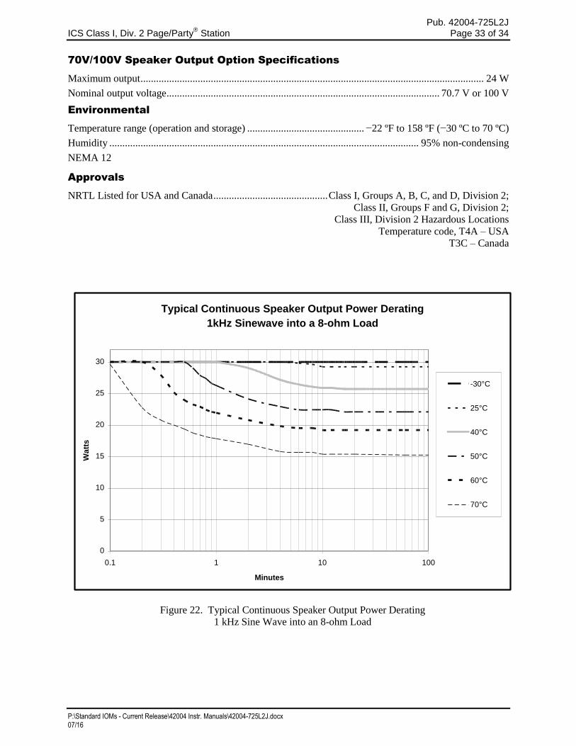
70V/100V Speaker Output Option Specifications
Maximum output .................................................................................................................................... 24 W
Nominal output voltage ......................................................................................................... 70.7 V or 100 V
Environmental
Temperature range (operation and storage) ............................................. −22 ºF to 158 ºF (−30 ºC to 70 ºC)
Humidity ....................................................................................................................... 95% non-condensing
NEMA 12
Approvals
NRTL Listed for USA and Canada ............................................ Class I, Groups A, B, C, and D, Division 2;
Class II, Groups F and G, Division 2;
Class III, Division 2 Hazardous Locations
Temperature code, T4A – USA
T3C – Canada
Figure 22. Typical Continuous Speaker Output Power Derating
1 kHz Sine Wave into an 8-ohm Load
Typical Continuous Speaker Output Power Derating
1kHz Sinewave into a 8-ohm Load
0
5
10
15
20
25
30
0.1 1 10 100
Minutes
Wa
tts
-30°C
25°C
40°C
50°C
60°C
70°C
Pub. 42004-725L2J ICS Class I, Div. 2 Page/Party
® Station Page 34 of 34
P:\Standard IOMs - Current Release\42004 Instr. Manuals\42004-725L2J.docx 07/16
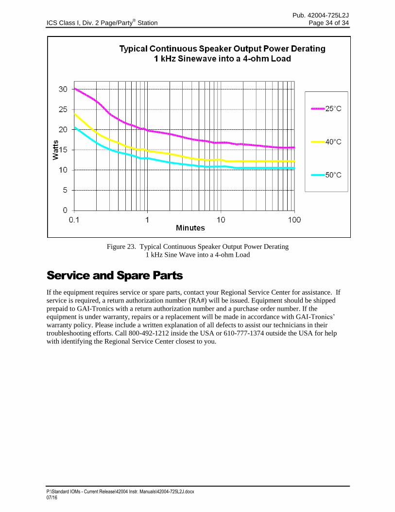
Figure 23. Typical Continuous Speaker Output Power Derating
1 kHz Sine Wave into a 4-ohm Load
Service and Spare Parts
If the equipment requires service or spare parts, contact your Regional Service Center for assistance. If
service is required, a return authorization number (RA#) will be issued. Equipment should be shipped
prepaid to GAI-Tronics with a return authorization number and a purchase order number. If the
equipment is under warranty, repairs or a replacement will be made in accordance with GAI-Tronics’
warranty policy. Please include a written explanation of all defects to assist our technicians in their
troubleshooting efforts. Call 800-492-1212 inside the USA or 610-777-1374 outside the USA for help
with identifying the Regional Service Center closest to you.
(Rev. 10/06)
WarrantyEquipment. GAI-Tronics warrants for a period of one (1) year from the date of shipment, that anyGAI-Tronics equipment supplied hereunder shall be free of defects in material and workmanship, shallcomply with the then-current product specifications and product literature, and if applicable, shall be fitfor the purpose specified in the agreed-upon quotation or proposal document. If (a) Seller’s goods proveto be defective in workmanship and/or material under normal and proper usage, or unfit for the purposespecified and agreed upon, and (b) Buyer’s claim is made within the warranty period set forth above,Buyer may return such goods to GAI-Tronics’ nearest depot repair facility, freight prepaid, at which timethey will be repaired or replaced, at Seller’s option, without charge to Buyer. Repair or replacement shallbe Buyer’s sole and exclusive remedy. The warranty period on any repaired or replacement equipmentshall be the greater of the ninety (90) day repair warranty or one (1) year from the date the originalequipment was shipped. In no event shall GAI-Tronics warranty obligations with respect to equipmentexceed 100% of the total cost of the equipment supplied hereunder. Buyer may also be entitled to themanufacturer’s warranty on any third-party goods supplied by GAI-Tronics hereunder. The applicabilityof any such third-party warranty will be determined by GAI-Tronics.
Services. Any services GAI-Tronics provides hereunder, whether directly or through subcontractors,shall be performed in accordance with the standard of care with which such services are normallyprovided in the industry. If the services fail to meet the applicable industry standard, GAI-Tronics willre-perform such services at no cost to buyer to correct said deficiency to Company's satisfaction providedany and all issues are identified prior to the demobilization of the Contractor’s personnel from the worksite. Re-performance of services shall be Buyer’s sole and exclusive remedy, and in no event shall GAI-Tronics warranty obligations with respect to services exceed 100% of the total cost of the servicesprovided hereunder.
Warranty Periods. Every claim by Buyer alleging a defect in the goods and/or services providedhereunder shall be deemed waived unless such claim is made in writing within the applicable warrantyperiods as set forth above. Provided, however, that if the defect complained of is latent and notdiscoverable within the above warranty periods, every claim arising on account of such latent defect shallbe deemed waived unless it is made in writing within a reasonable time after such latent defect is orshould have been discovered by Buyer.
Limitations / Exclusions. The warranties herein shall not apply to, and GAI-Tronics shall not beresponsible for, any damage to the goods or failure of the services supplied hereunder, to the extentcaused by Buyer’s neglect, failure to follow operational and maintenance procedures provided with theequipment, or the use of technicians not specifically authorized by GAI-Tronics to maintain or service theequipment. THE WARRANTIES AND REMEDIES CONTAINED HEREIN ARE IN LIEU OF ANDEXCLUDE ALL OTHER WARRANTIES AND REMEDIES, WHETHER EXPRESS OR IMPLIED BYOPERATION OF LAW OR OTHERWISE, INCLUDING ANY WARRANTIES OFMERCHANTABILITY OR FITNESS FOR A PARTICULAR PURPOSE.
Return PolicyIf the equipment requires service, contact your Regional Service Center for a return authorization number(RA#). Equipment should be shipped prepaid to GAI-Tronics with a return authorization number and apurchase order number. If the equipment is under warranty, repairs or a replacement will be made inaccordance with the warranty policy set forth above. Please include a written explanation of all defects toassist our technicians in their troubleshooting efforts.
Call 800-492-1212 (inside the USA) or 610-777-1374 (outside the USA) for help identifying theRegional Service Center closest to you.


![c+za08fsf] !* g+= df plNnlvt lg0f{o g+= **^(/cite>lg0f{o](https://img.pdfslide.tips/doc/110x75/5ac3e86e7f8b9ae06c8cbb58/cza08fsf-g-df-plnnlvt-lg0fo-g-.jpg)