Embed Size (px)
Citation preview

7/25/2019 iecpas62544ed1.0en.pdf
http://slidepdf.com/reader/full/iecpas62544ed10enpdf 1/58
IEC/PAS 62544
Edition 1.0
2008-02
PUBLICLY AVAILABLESPECIFICATION
PRE-STANDARD
Active filters in HVDC applications
I E C / P A S
6 2 5 4 4 : 2 0 0 8
( E )
C o p y r i gh
t e d m
a t er i al l i c
en
s e d t oE l e
c t r i c i t y of V i e
t n am b
y T h
om
s on
S c i en
t i f i c ,I n
c
. ( www. t e
c h
s t r e e t . c om
) .T h i s
c o p y d ownl o
a d e d on2
0 1 4 - 0 1 - 0
6 0 8 : 2
6 : 3
0 - 0
6 0 0 b y a u t h or i z
e d u s er P h
am V
an
c h i .
N of ur t h
er r e
pr o
d u c t i on
or
d i s
t r i b u t i oni
s p er mi t t e
d .

7/25/2019 iecpas62544ed1.0en.pdf
http://slidepdf.com/reader/full/iecpas62544ed10enpdf 2/58
THIS PUBLICATION IS COPYRIGHT PROTECTED
Copyright © 2008 IEC, Geneva, Switzerland
All rights reserved. Unless otherwise spec ified, no part of this publi cation may be reproduced or util ized in any formor by any means, electronic or mechanical, including photocopying and microfilm, without permission in writing from
either IEC or IEC's member National Committee in the country of the requester.If you have any questions about IEC copyright or have an enquiry about obtaining additional rights to this publication,please contact the address below or your local IEC member National Committee for further information.
IEC Central Office3, rue de VarembéCH-1211 Geneva 20SwitzerlandEmail: [email protected] Web: www.iec.ch
About the IEC
The International Electrotechnical Commission (IEC) is the leading global organization that prepares and publishesInternational Standards for all electrical, electronic and related technologies.
About IEC publications
The technical content of IEC publications is kept under constant review by the IEC. Please make sure that you have thelatest edition, a corrigenda or an amendment might have been published.
Catalogue of IEC publications: www.iec.ch/searchpub The IEC on-line Catalogue enables you to search by a variety of criteria (reference number, text, technical committee,…).It also gives information on projects, withdrawn and replaced publications.
IEC Just Published: www.iec.ch/online_news/justpub Stay up to date on all new IEC publications. Just Published details twice a month all new publications released. Availableon-line and also by email.
Electropedia: www.electropedia.org The world's leading online dictionary of electronic and electrical terms containing more than 20 000 terms and definitionsin English and French, with equivalent terms in additional languages. Also known as the International ElectrotechnicalVocabulary online.
Customer Service Centre: www.iec.ch/webstore/custserv If you wish to give us your feedback on this publication or need further assistance, please visit the Customer ServiceCentre FAQ or contact us:
Email: [email protected] Tel.: +41 22 919 02 11Fax: +41 22 919 03 00
C o p y r i gh
t e d m
a t er i al l i c
en
s e d t oE l e
c t r i c i t y of V i e
t n am b
y T h
om
s on
S c i en
t i f i c ,I n
c
. ( www. t e
c h
s t r e e t . c om
) .T h i s
c o p y d ownl o
a d e d on2
0 1 4 - 0 1 - 0
6 0 8 : 2
6 : 3
0 - 0
6 0 0 b y a u t h or i z
e d u s er P h
am V
an
c h i .
N of ur t h
er r e
pr o
d u c t i on
or
d i s
t r i b u t i oni
s p er mi t t e
d .

7/25/2019 iecpas62544ed1.0en.pdf
http://slidepdf.com/reader/full/iecpas62544ed10enpdf 3/58
IEC/PAS 62544
Edition 1.0 2008-02
PUBLICLY AVAILABLESPECIFICATION
PRE-STANDARD
Active filters in HVDC applications
INTERNATIONAL
ELECTROTECHNICAL
COMMISSION XAICS 29.240.99
PRICE CODE
ISBN 2-8318-9595-2
C o p y r i gh
t e d m
a t er i al l i c
en
s e d t oE l e
c t r i c i t y of V i e
t n am b
y T h
om
s on
S c i en
t i f i c ,I n
c
. ( www. t e
c h
s t r e e t . c om
) .T h i s
c o p y d ownl o
a d e d on2
0 1 4 - 0 1 - 0
6 0 8 : 2
6 : 3
0 - 0
6 0 0 b y a u t h or i z
e d u s er P h
am V
an
c h i .
N of ur t h
er r e
pr o
d u c t i on
or
d i s
t r i b u t i oni
s p er mi t t e
d .

7/25/2019 iecpas62544ed1.0en.pdf
http://slidepdf.com/reader/full/iecpas62544ed10enpdf 4/58
– 2 – PAS 62544 © IEC:2008(E)
CONTENTS
FOREWORD......................................................................................................................................... 4
0.1 INTRODUCTION.............................................................................................................. 50.2 SCOPE................................................................................................................................ 5
1 ACTIVE DC FILTERS IN HVDC APPLICATIONS ............................................................. 6
1.1 INTRODUCING ACTIVE DC FILTERS ...............................................................................6
1.2 TECHNICAL DEMANDS TO DISTURBANCES ON THE DC SIDE .............................. 7
1.3 DESCRIPTION OF ACTIVE DC FILTERS ....................................................................... 7
1.3.1 Semiconductors available for a power stage .......................................................... 8
1.3.2 Types of converters available ................................................................................. 8
1.3.3 Connections of the active DC filter ........................................................................ 91.3.4 Characteristics of installed active DC filters ........................................................ 11
1.4 MAIN COMPONENTS IN AN ACTIVE DC FILTER ..................................................... 11
1.4.1 The Passive Part ....................................................................................................12
1.4.2 The current transducer ...........................................................................................13
1.4.3 The control system ............................................................................................... 14
1.4.4 The amplifier ........................................................................................................ 14
1.4.5 The Transformer .................................................................................................. 14
1.4.6 Protection circuit and arrester .............................................................................. 14
1.4.7 Bypass switch and disconnectors...............................................................................15
1.5 ACTIVE DC FILTER CONTROL .................................................................................... 15
1.5.1 Active DC Filter Control methods ........................................................................ 15
1.6 PROJECT DESCRIPTIONS AND DC FILTER SOLUTIONS ........................................ 18
1.6.1 Skagerrak 3 HVDC Intertie .................................................................................. 18
1.6.2 Baltic Cable HVDC Link ...................................................................................... 19
1.6.3 Chandrapur-Padghe HVDC power transmission project ...................................... 20
1.6.4 Tian - Guang long distance HVDC project .......................................................... 21
1.6.5 EGAT-TNB (Thailand-Malaysia) HVDC Interconnection ................................... 21
1.7 PERFORMANCE OF THE SKAGERRAK 3 HVDC INTERTIE ACTIVE DC
FILTER ............................................................................................................................. 22
1.8 CONCLUSIONS ON ACTIVE DC FILTERS .................................................................. 24
2 ACTIVE AC FILTERS IN HVDC APPLICATIONS ........................................................... 25
2.1 INTRODUCING ACTIVE AC FILTERS ......................................................................... 25
2.2 TECHNICAL DEMANDS TO HARMONIC DISTURBANCES ON THE AC SIDE .... 25
2.3 PASSIVE FILTERS ......................................................................................................... 26
2.3.1 Conventional passive filters ................................................................................. 26
2.3.2 Continuously tuned passive filters ........................................................................ 27
C o p y r i gh
t e d m
a t er i al l i c
en
s e d t oE l e
c t r i c i t y of V i e
t n am b
y T h
om
s on
S c i en
t i f i c ,I n
c
. ( www. t e
c h
s t r e e t . c om
) .T h i s
c o p y d ownl o
a d e d on2
0 1 4 - 0 1 - 0
6 0 8 : 2
6 : 3
0 - 0
6 0 0 b y a u t h or i z
e d u s er P h
am V
an
c h i .
N of ur t h
er r e
pr o
d u c t i on
or
d i s
t r i b u t i oni
s p er mi t t e
d .

7/25/2019 iecpas62544ed1.0en.pdf
http://slidepdf.com/reader/full/iecpas62544ed10enpdf 5/58
PAS 62544 © IEC:2008(E) – 3 –
2.4 REASONS FOR USING ACTIVE FILTERS IN HVDC SCHEMES ............................... 28
2.5 OPERATION PRINCIPLES OF ACTIVE FILTERS ....................................................... 29
2.5.1 Shunt connected active filter .................................................................................... 29
2.5.2 Series connected active filter .................................................................................... 302.6 PARALLEL AND SERIES CONFIGURATION .................................................................. 31
2.6.1 Hybrid filter schemes ................................................................................................ 32
2.7 CONVERTER CONFIGURATIONS .................................................................................... 33
2.7.1 Converters ................................................................................................................ 33
2.7.2 STATCOM ............................................................................................................... 35
2.8 ACTIVE AC FILTER CONFIGURATIONS ........................................................................ 37
2.8.1 Active ac filters for low voltage application ............................................................. 37
2.8.2 Active ac filters for medium voltage application ...................................................... 37
2.8.3 Active ac filters for HVDC applications ................................................................... 37
2.9 SERIES CONNECTED ACTIVE FILTERS ......................................................................... 38
2.10 CONTROL SYSTEM ........................................................................................................... 39
2.10.1 Introduction .............................................................................................................. 39
2.10.2 Description of a Generic Active Power Filter Controller .......................................... 39
2.10.3 Calculation of Reference Current ............................................................................. 40
2.10.4 Synchronous Reference Frame (SRF) ....................................................................... 41
2.10.5 Other Control Approaches ....................................................................................... 42
2.10.6 HVDC AC Active Filter Control Approach .............................................................. 43
2.11 EXISTING ACTIVE AC FILTER APPLICATIONS ............................................................ 43
2.11.1 Low and medium voltage .......................................................................................... 43
2.11.2 High voltage applications ......................................................................................... 43
2.12 OVERVIEW ON FILTER SOLUTIONS FOR HVDC SYSTEMS ....................................... 46
2.12.1 Solution with conventional passive filters ................................................................ 46
2.12.2 Solution with continuously tuned passive filters ...................................................... 47
2.12.3 Solution with active filters ....................................................................................... 47
2.12.4 Solution with continuously tuned passive filters and active filters ........................... 48
2.12.5 Study cases with the Cigré HVDC model ................................................................. 48
2.13 FUTURE TECHNOLOGIES ................................................................................................. 50
2.14 CONCLUSIONS ON ACTIVE AC FILTERS ...................................................................... 50
3 BIBLIOGRAPHY ........................................................................................................................ 51
C o p y r i gh
t e d m
a t er i al l i c
en
s e d t oE l e
c t r i c i t y of V i e
t n am b
y T h
om
s on
S c i en
t i f i c ,I n
c
. ( www. t e
c h
s t r e e t . c om
) .T h i s
c o p y d ownl o
a d e d on2
0 1 4 - 0 1 - 0
6 0 8 : 2
6 : 3
0 - 0
6 0 0 b y a u t h or i z
e d u s er P h
am V
an
c h i .
N of ur t h
er r e
pr o
d u c t i on
or
d i s
t r i b u t i oni
s p er mi t t e
d .

7/25/2019 iecpas62544ed1.0en.pdf
http://slidepdf.com/reader/full/iecpas62544ed10enpdf 6/58
– 4 – PAS 62544 © IEC:2008(E)
INTERNATIONAL ELECTROTECHNICAL COMMISSION ____________
ACTIVE FILTERS IN HVDC APPLICATIONS
FOREWORD
1) The International Electrotechnical Commission (IEC) is a worldwide organization for standardization comprising allnational electrotechnical committees (IEC National C ommittees). The object of IEC is to promote international co-operation on all questions concerning standardization in the electrical and electronic fields. To this end and inaddition to other activities, IEC publishes International Standards, Technical Specifications, Technical Reports,Publicly Available Specifications (PAS) and Guides (hereafter referred to as “IEC Publication(s)”). Theirpreparation is entrusted to technical committees; any IEC National Committee interested in the subject dealt withmay participate in this preparatory work. International, governmental and non-governmental organizations liaisingwith the IEC also participate in this preparation. IEC collaborates closely with the International Organization forStandardization (ISO) in accordance with conditions determined by agreement between the two o rganizations.
2) The formal decisions or agreements of IEC on technical matters express, as nearly as possible, an internationalconsensus of opinion on the relevant subjects since each technical committee has representation from all
interested IEC National Committees.3) IEC Publications have the form of recommendations for international use and are accepted by IEC National
Committees in that sense. While all reasonable efforts are made to ensure that the technical content of IECPublications is accurate, IEC cannot be held responsible for the way in which they are used or for anymisinterpretation by any end user.
4) In order to promote international uniformity, IEC National Committees undertake to apply IEC Publicationstransparently to the maximum extent possible in their national and regional publications. Any divergence betweenany IEC Publication and the corresponding national or regional publication shall be clearly indicated in the latter.
5) IEC provides no marking procedure to indicate its approval and cannot be rendered responsible for any equipmentdeclared to be in conformity with an IEC Publication.
6) All users should ensure that they have the latest edition of this publication.
7) No liability shall attach to IEC or its directors, employees, servants or agents including individual experts andmembers of its technical committees and IEC National Committees for any personal injury, property damage orother damage of any nature whatsoever, whether direct or indirect, or for costs (including legal fees) and
expenses arising out of the publication, use of, or reliance upon, this IEC Publication or any other IECPublications.
8) Attention is drawn to the Normative references cited in this publication. Use of the referenced publications isindispensable for the correct application of this publication.
9) Attention is drawn to the possibility that some of the elements of this IEC Publication may be the subject of patentrights. IEC shall not be held responsible for identifying any or all such patent rights.
A PAS is a technical specifica tion not fulfi lling the requirements for a standard, but madeavailable to the public and established in an organization operating under given procedures.
IEC-PAS 62544 was submitted by the CIGRÉ (International Council on Large Electric Systems)and has been processed by subcommittee 22F: Power electronics for electrical transmission anddistr ibution systems, of IEC technical committee 22: Power electronic systems and equipment.
The text of this PAS is based on thefollowing document:
This PAS was approved forpublication by the P-members of thecommittee concerned as indicated in
the following document
Draft PAS Report on voting
22F/130/NP 22F/147/RVN
Following publication of this PAS, which is a pre-standard publication, the technical committeeor subcommittee concerned will transform it into an International Standard.
An IEC-PAS l icence of copyright and assignment of copyright has been signed by the IEC andCIGRÉ and is recorded at the Central Office.
This PAS shall remain valid for an initial maximum period of three years starting from thepublication date. The validity may be extended for a single three-year period, following which itshall be revised to become another type of normative document or shall be withdrawn.
C o p y r i gh
t e d m
a t er i al l i c
en
s e d t oE l e
c t r i c i t y of V i e
t n am b
y T h
om
s on
S c i en
t i f i c ,I n
c
. ( www. t e
c h
s t r e e t . c om
) .T h i s
c o p y d ownl o
a d e d on2
0 1 4 - 0 1 - 0
6 0 8 : 2
6 : 3
0 - 0
6 0 0 b y a u t h or i z
e d u s er P h
am V
an
c h i .
N of ur t h
er r e
pr o
d u c t i on
or
d i s
t r i b u t i oni
s p er mi t t e
d .

7/25/2019 iecpas62544ed1.0en.pdf
http://slidepdf.com/reader/full/iecpas62544ed10enpdf 7/58
PAS 62544 © IEC:2008(E) – 5 –
ACTIVE FILTERS IN HVDC APPLICATIONS
By Cigré Working Group 14.28
0.1 INTRODUCTION
Fourteen active DC filters and one active AC filter exist already in HVDC converter stations. Theinterest in active filters for HVDC systems is mainly due the fact that a single active filter is able tomitigate effectively diverse harmonics simultaneously, which otherwise would require several passivefilters to achieve a comparable result. They can also contribute to reducing the size of the smoothingreactors used at the DC side and to reducing losses. They are also able to cope with harmonic resonance problems and to adapt themselves to changes in the harmonic impedance of the system, which areimportant characteristics, especially for the connection to the AC side.
0.2 SCOPE
This report prepared by Working Group 14.28 presents both DC and AC active filters, including theexisting installations. The items of the report are basically arranged in two consecutive parts, the first onetreating the DC application, and the second covering the AC filters. As active DC and AC filters sharemany concepts, the reader interested in such a subject is encouraged to search for it in both parts.
C o p y r i gh
t e d m
a t er i al l i c
en
s e d t oE l e
c t r i c i t y of V i e
t n am b
y T h
om
s on
S c i en
t i f i c ,I n
c
. ( www. t e
c h
s t r e e t . c om
) .T h i s
c o p y d ownl o
a d e d on2
0 1 4 - 0 1 - 0
6 0 8 : 2
6 : 3
0 - 0
6 0 0 b y a u t h or i z
e d u s er P h
am V
an
c h i .
N of ur t h
er r e
pr o
d u c t i on
or
d i s
t r i b u t i oni
s p er mi t t e
d .

7/25/2019 iecpas62544ed1.0en.pdf
http://slidepdf.com/reader/full/iecpas62544ed10enpdf 8/58
– 6 – PAS 62544 © IEC:2008(E)
1 ACTIVE DC FILTERS IN HVDC APPLICATIONS
1.1 INTRODUCING ACTIVE DC FILTERS
The conversion process in an HVDC transmission system introduces harmonic currents into the DCtransmission lines and the AC grid connected to the HVDC converters. These harmonic currents maycause interference in the adjacent systems, such as telecommunication equipment. The conventionalsolution to reduce the harmonics has been to install passive filters in HVDC converter stations [1]1).When the power line consists of cables, this filtering is normally not necessary. The development of power electronics devices and digital computers has made it possible to achieve a powerful new way forfurther reduction of harmonic levels, namely, active filters.
The active filters can be divided into two groups,active AC and DC filters. Active DC filterinstallations are in operation in several HVDC linksand have been economically competitive due to
increased demand on telephone interference levels onthe DC overhead lines (Figure 1.1.1). An active ACfilter is already in operation as well. In addition tothe active DC filter function of mitigating theharmonic currents on the DC overhead lines, theactive AC filters may be part of several solutions inthe HVDC scheme to improve reactive powerexchange with the AC grid and to improve thedynamic stability. Already in the 1960s there were attempts to develop and install an active filter in a HVDC
converter station in Sweden, but the project turned out unsuccessfully. In the middle of the 1980s the technological development of the presently installed active filters was initiated. Mainly two reasons make the projects successful. Primarily, the prices on semiconductors have decreased dramatically and secondly, digital computers are getting more powerful.
The reasons to develop first the active DC Filter and subsequently the active AC filter, were:
• Active AC and DC filters consist of two parts, a passive part and a corresponding active part, which areloaded with the same currents. Due to the fact that the passive AC filter is used to supply the HVDCconverter demand of reactive power and thereby loaded with the fundamental current, the required
rating of the DC filter active part is lower than that of the AC filter active part. • The control philosophy for the active DC filter is less complex than for the AC one.
• The present HVDC applications where active AC filters are feasible will be limited, due to the factthat AC filters are also required to supply the HVDC converter demand of reactive power. The filtersize is therefore often well above the filtering demand.
In future HVDC projects a new converter technology may be applied, implying that the reactive powercan be separated from the AC filters and thereby make the active AC filter more feasible. The most promising technologies are the Capacitor Commutated Converters (CCC) and the Controlled SeriesCapacitor Converter (CSCC), but GTO controlled converters are also able to keep the reactive power balance from the converter within a minimum.
1) Figures in square brackets refer to the Bibliography.
Figure 1.1.1 Conceptual diagram of allowableinterference level and DC filter cost
C o p y r i gh
t e d m
a t er i al l i c
en
s e d t oE l e
c t r i c i t y of V i e
t n am b
y T h
om
s on
S c i en
t i f i c ,I n
c
. ( www. t e
c h
s t r e e t . c om
) .T h i s
c o p y d ownl o
a d e d on2
0 1 4 - 0 1 - 0
6 0 8 : 2
6 : 3
0 - 0
6 0 0 b y a u t h or i z
e d u s er P h
am V
an
c h i .
N of ur t h
er r e
pr o
d u c t i on
or
d i s
t r i b u t i oni
s p er mi t t e
d .
7/25/2019 iecpas62544ed1.0en.pdf
http://slidepdf.com/reader/full/iecpas62544ed10enpdf 9/58
PAS 62544 © IEC:2008(E) – 7 –
1.2 TECHNICAL DEMANDS TO DISTURBANCES ON THE DC SIDE
The main reason for specifying demands on the DC circuit is to keep disturbances in nearby telephonelines within an acceptable limit, which will vary depending on whether the telephone system consists ofoverhead lines or underground cables, which are generally shielded and therefore have a better immunity[2]. A summary is given below to illustrate the demands which made it feasible to install the activefilters. As described, the demand on disturbances can appear as an harmonic current on the DC line or asan induced voltage “Uind” in a fictive telephone line. The reader should keep in mind that the harmonicdemand, the specific HVDC system and surroundings (earth resistivity, telephone system etc.) alltogether define the DC filter solution.
The specified demand:
• The induced voltage “Uind” in a theoretically 1 km telephone line situated 1 km from the DC overheadline shall be below 10 mV for monopolar operation.
• A one-minute mean value of the equivalent psophometric current “I pe” fed into the DC pole overheadline shall be below 400 mA.
The mentioned induced voltage and the equivalent psophometric current are defined as:
where f n is the frequency of the n-th harmonic, M is the mutual inductance between the telephone line and
the power line, k n =f180
*0
n , In is the vectorial sum of the n-th harmonic current flowing in the line
conductors (Common mode/earth mode current). pn is the n-th psophometric weighting factor defined by
CCITT Directives 1963 [3] (see also Table 1.2.1) and p16 is the 16th psophometric weighting factor. The
characteristic harmonics n=12, 24, 36, 48 as well as the non-characteristic harmonics up to n = 50 shall
be considered.
Table 1.2.1 The psophometric weighting factor at selected frequencies.
Frequency/Hz 50
n 1
pn Factor 0.0007
pn*k n 0.00004
100
2
0.009
0.001
300
6
0.295
0.111
600
12
0.7940.595
800
16
1.000
1.000
1000
20
1.122
1.403
1200
24
1.000
1.500
1800
36
0.760
1.710
2400
48
0.634
1.902
3000
60
0.525
1.969
1.3 DESCRIPTION OF ACTIVE DC FILTER
Active DC filters use a controllable converter to introduce currents in the network, presenting a
waveform which counteracts the harmonics. This clause describes types of power stages, converters to be
C o p y r i gh
t e d m
a t er i al l i c
en
s e d t oE l e
c t r i c i t y of V i e
t n am b
y T h
om
s on
S c i en
t i f i c ,I n
c
. ( www. t e
c h
s t r e e t . c om
) .T h i s
c o p y d ownl o
a d e d on2
0 1 4 - 0 1 - 0
6 0 8 : 2
6 : 3
0 - 0
6 0 0 b y a u t h or i z
e d u s er P h
am V
an
c h i .
N of ur t h
er r e
pr o
d u c t i on
or
d i s
t r i b u t i oni
s p er mi t t e
d .

7/25/2019 iecpas62544ed1.0en.pdf
http://slidepdf.com/reader/full/iecpas62544ed10enpdf 10/58
– 8 – PAS 62544 © IEC:2008(E)
used in active filters and the possible connections in HVDC schemes.
1.3.1 Semiconductors available for a power stage
Three types of semiconductors, suitable for use in an active filter, are available at present:
• The MosFET
• The IGBT
• The GTO
The MosFET is an excellent switching device capable of switching at very high frequencies withrelatively low losses, but with limited power handling capability.
The IGBT has a switching frequency capability which, although very good and sufficient to handle thefrequencies within the active DC filter range, is inferior to the MosFET. However the IGBT powerhandling is significantly higher than the MosFET.
The GTO has the highest power handling capacity, but with a relatively limited switching speed far belowthe required frequency range for active DC filter. The use of GTO will probably be limited to handling
frequencies below a few hundred of Hertz.
The relatively high frequency band for active DC filtering excludes the use of thyristors and GTO. Eventhough the MosFET and IGBT are suited as switching elements in a power stage, the limited powerhandling capacity on MosFET and the installed cost evaluations tend to point to the use of IGBT in future power stages.
1.3.2 Types of converters available
Two basic types of switching converters are possible in an active DC filter; the current-source converter(CSC) using inductive energy storage and the voltage-source converter (VSC) using capacitive energystorage.
In a CSC the DC element is a current source, which normallyconsists of a DC voltage source power supply in series with aninductor. For correct operation the current should flowcontinuously in the inductor. Hence, if AC current is notrequired, current must be by-passed within the converter. Thisfact restricts the switching actions. A simple CSC is shown inFigure 1.3.1.
1.3.2.2 Voltages source converters (VSC)
In the VSC the DC element is a voltage source. This may be aDC power supply or, in the case of an active DC filterapplication, an energy storage unit. In practice, the voltagesource for an active DC filter power stage is usually a capacitorwith a small power supply to offset the power stage losses. AVSC also has the property that its AC output appears as avoltage source.
A circuit of simple VSC is shown in Figure 1.3.2.
Figure 1.3.1 Simple current source converter
Figure 1.3.2 Simple voltage source converter
C o p y r i gh
t e d m
a t er i al l i c
en
s e d t oE l e
c t r i c i t y of V i e
t n am b
y T h
om
s on
S c i en
t i f i c ,I n
c
. ( www. t e
c h
s t r e e t . c om
) .T h i s
c o p y d ownl o
a d e d on2
0 1 4 - 0 1 - 0
6 0 8 : 2
6 : 3
0 - 0
6 0 0 b y a u t h or i z
e d u s er P h
am V
an
c h i .
N of ur t h
er r e
pr o
d u c t i on
or
d i s
t r i b u t i oni
s p er mi t t e
d .

7/25/2019 iecpas62544ed1.0en.pdf
http://slidepdf.com/reader/full/iecpas62544ed10enpdf 11/58
PAS 62544 © IEC:2008(E) – 9 –
1.3.2.3 Comparison between current and voltage source converters
The CSC has a high internal impedance for currents through the converter, while the VSC has a lowimpedance. The VSC has no constraints on the switching pattern that can be employed, while the CSC isrestricted as described above. The necessity for continuous current in the CSC, combined with the factthat (neglecting superconductivity) an inductor has higher losses than a capacitor, ensures that the losses
in the CSC are higher than those in the VSC. Another parameter influencing losses is that a CSC needsswitching devices which can block reverse voltage. Most of the operating semiconductors do not fulfilthis requirement. In this case an extra diode in series with each device is necessary and this againincreases the losses. Some GTOs are able to support reverse voltage, but these are less common than theGTOs which do not support reverse voltage. The former have higher losses than the more commondevices.
Conclusion: Considering the above properties of CSC and VSC, the type most suited for power stageapplications, particularly high power, is the VSC. The VSC has been preferred in all HVDC projectsapplicable today.
1.3.3 Connections of the active DC filter
Advantages and disadvantage of connecting the active filters at locations shown in Figure 1.3.3 have beendiscussed in several papers [4,5,6,7,8,9,10]. The active filters can be connected either as shunt activefilters or as series active filters.
Figure 1.3.3 Possible connections of active DC filters
1.3.3.1 The "active filter 1" connection
The active DC filter realised in HVDC schemes today is connected as the shunt “active filter 1” in Figure1.3.3. By connecting the active filter in series with the passive DC filter, usually a 12/24th double tuned
C o p y r i gh
t e d m
a t er i al l i c
en
s e d t oE l e
c t r i c i t y of V i e
t n am b
y T h
om
s on
S c i en
t i f i c ,I n
c
. ( www. t e
c h
s t r e e t . c om
) .T h i s
c o p y d ownl o
a d e d on2
0 1 4 - 0 1 - 0
6 0 8 : 2
6 : 3
0 - 0
6 0 0 b y a u t h or i z
e d u s er P h
am V
an
c h i .
N of ur t h
er r e
pr o
d u c t i on
or
d i s
t r i b u t i oni
s p er mi t t e
d .

7/25/2019 iecpas62544ed1.0en.pdf
http://slidepdf.com/reader/full/iecpas62544ed10enpdf 12/58
– 10 – PAS 62544 © IEC:2008(E)
filter, the active filter rating can be reduced. A VSC is chosen in order to make the smallest influence onthe original function of the passive filter, especially on frequencies where the control algorithm is notactive.
1.3.3.2 The "active filter 2" connection
The “active filter 2” in Figure 1.3.3 is similar to the shunt “active filter 1” solution. The powerconsumption of the tuning circuit in the passive filter will probably reduce the efficiency for injectingharmonic currents to counteract the disturbance current and thereby increase the rating of the converter.There may be an additional inductance inserted in series with the active part.
1.3.3.3 The "active filter 3" connection
The “active filter 3” in Figure 1.3.3 is a series active filter described in [11], but there is a lack ofknowledge of such a system. The active filter converter must be connected to the HVDC system by acoupling transformer “Tc”. To prevent saturation of the coupling transformer “Tc” by the DC load currentof the HVDC converter “Idconv”, the core must have an air gap.
In this way, the coupling transformer “Tc” is a DC reactor with a galvanic insulated auxiliary winding toconnect the active filter (converter). To achieve no ripple voltage at the point of connection of the passiveDC filter and therefor no ripple current in the DC pole line, the active filter must generate across the mainwinding “Tc” a voltage which compensates the ripple voltage “Ur ” of the DC side of the HVDCconverter.
The AC load current “Ir ” of the main winding of “Tc” is determined by “Ur ” and its inductance value “Lr ”,the converter transformer inductance and the smoothing reactor inductance. The rating of “T c” isdetermined by “(Idconv + Ir )
2*Lr . The rating of the active filter (converter) is determined by “Udr 2/Lr ”. Hence
the economical optimisation between the active and passive part of the active filter can be adjusted byincreasing “Lr ”. The rating of “Tc” will be increased and the rating of the active filter part will bedecreased or vice versa.
The smoothing reactor (which is already designed for “Udr ”) is eventually an alternative for “Tc”,although is must be relocated to the neutral side of the HVDC converter valve and provided with anauxiliary winding.
The advantages of this connection are:
• there are no harmonics in the HVDC converter DC current;
• the control algorithm of a series filter will probably be simplified compared to the shunt filter control.
The disadvantages are:
• Even by an optimal design, the rating of “Tc” and the active filter part will be considerable.
• The “Tc” side of the HVDC converter has no earth potential, which should be considered in the designof the HVDC converter and the transformer “Tc”.
1.3.3.4 The "active filter 4" connection
The “active filter 4” in Figure 1.3.3 is a series active filter fundamentally with the same configuration and problems as the “active filter 3”. The filter is connected at the pole bus on the line side of the DC filtercapacitor. The major advantage of this arrangement is that the active filter rating (due to the fact that theHVDC converter output ripple voltage is attenuated already by the passive filter) will be considerably lessthan the “active filter 3” connection. The disadvantage of this arrangement is that the filter is situated atline potential and that the filter must conduct the whole DC current.
C o p y r i gh
t e d m
a t er i al l i c
en
s e d t oE l e
c t r i c i t y of V i e
t n am b
y T h
om
s on
S c i en
t i f i c ,I n
c
. ( www. t e
c h
s t r e e t . c om
) .T h i s
c o p y d ownl o
a d e d on2
0 1 4 - 0 1 - 0
6 0 8 : 2
6 : 3
0 - 0
6 0 0 b y a u t h or i z
e d u s er P h
am V
an
c h i .
N of ur t h
er r e
pr o
d u c t i on
or
d i s
t r i b u t i oni
s p er mi t t e
d .

7/25/2019 iecpas62544ed1.0en.pdf
http://slidepdf.com/reader/full/iecpas62544ed10enpdf 13/58
PAS 62544 © IEC:2008(E) – 11 –
1.3.3.5 The "active filter 5" connection
There has not been any article describing “active filter 5a and 5b” in Figure 1.3.3. The application of sucha filter is expected to be limited to either higher frequencies or lower frequencies and not the wholefrequency range as the “active filter 1 and 2”.
1.3.3.6 Conclusion on active filter connections The advantages and disadvantages of the most possible connections of the active part of the DC filterhave been described above. The main conclusion is that series connections of active filters on the DC sideare possible, but in light of the facts available today are not recommendable.
The injected power for active filtering can be reduced by choosing the optimum line injection point on the passive circuit or the DC line. All active DC filter applications implemented today and in the near futurewill use the “active filter 1” solution in Figure 1.3.3. The remaining part of this document thereforediscusses the “active filter 1” solution.
1.3.4 Characteristics of installed active DC filters
The active DC filters today (Figure 1.4.1), are connected in feedback control loop. The line current ismeasured by a current transducer. The current signal is passed through a light guide into a computer. Thecomputer calculates a signal to feed a VSC, so that the current injected at the pole line is in opposition tothe measured line current.
Characteristics of the active DC filters:
• frequency range 300 Hz -3000 Hz;
• the achieved harmonic current attenuation is high, at least 10 times more attenuation than thatachievements with the passive part alone, at all chosen frequencies in the whole frequency range(Figure 1.7.1);
• adaptable to variations of network frequency;
• compensate detuning effects of the passive DC filter;
• comparatively small size: the active part of the active DC filter can be fully assembled and tested at thefactory and then transported to site;
• significant changes in characteristics of the active DC filter can be achieved any time aftercommissioning within the active filter ratings by software changes without hardware modification.
1.4 MAIN COMPONENTS IN AN ACTIVE DC FILTER
The active DC filter is a hybrid filter consisting of a passive and an active part. The passive part canusually be defined as a double tuned passive filter which connects the active part with the DC line. Theactive part in the DC filter is defined as the components within the box shown in Figure 1.4.1. All thecomponents in the active part shall ensure proper function of the active filter in steady state conditionsand during faults.
Figure 1.4.1 shows the active filter components in the filters today.
C o p y r i gh
t e d m
a t er i al l i c
en
s e d t oE l e
c t r i c i t y of V i e
t n am b
y T h
om
s on
S c i en
t i f i c ,I n
c
. ( www. t e
c h
s t r e e t . c om
) .T h i s
c o p y d ownl o
a d e d on2
0 1 4 - 0 1 - 0
6 0 8 : 2
6 : 3
0 - 0
6 0 0 b y a u t h or i z
e d u s er P h
am V
an
c h i .
N of ur t h
er r e
pr o
d u c t i on
or
d i s
t r i b u t i oni
s p er mi t t e
d .

7/25/2019 iecpas62544ed1.0en.pdf
http://slidepdf.com/reader/full/iecpas62544ed10enpdf 14/58
– 12 – PAS 62544 © IEC:2008(E)
Figure 1.4.1 Filter components in the active filter
1.4.1 The Passive Part The main function of the passive part is to connect the active part with the high voltage DC line. Thereasons for choosing a double tuned filter are both an optimisation of the VSC cost compared with thedouble tuned circuit and to ensure a reasonable performance if the active part is not in operation.
The choice of the characteristics for the passive part, together with the size of the smoothing reactor, willinfluence the rating of the active part. The following example illustrates the rating requirements of theactive part with a fixed size smoothing reator when
• only a capacitor is used;
• a single tuned 12 harmonic filter is used;
• a double tuned 12/24 harmonic filter is used. Table 1.4.1 shows a scheme calculated from some typical measured current values from a 600 MW, 400kV HVDC converter connected to a 400 kV 50 Hz AC grid. The smoothing reactor has 200 mH, the maincapacitor has 1 µF. The root sum of squares of a typical measured current spectrum through thesmoothing reactor gives 15.7 Arms. The current spectrum is used to calculate the assumed voltage which isrequired for the active part to compensate the harmonics for the three mentioned filter configurationsshown in Figure 1.4.2.
The reader should pay attention to the fact that the calculated case in Table 1.4.1 is a simplified case, witha short overhead line connected to a long HVDC cable. The HVDC cable mitigates the influence from theother HVDC converter. The calculated example will only illustrate the impact of rating on the active partwith selection of different passive parts. In the “real” rating of the DC filter design, the designer has to
include various other parameters.
C o p y r i gh
t e d m
a t er i al l i c
en
s e d t oE l e
c t r i c i t y of V i e
t n am b
y T h
om
s on
S c i en
t i f i c ,I n
c
. ( www. t e
c h
s t r e e t . c om
) .T h i s
c o p y d ownl o
a d e d on2
0 1 4 - 0 1 - 0
6 0 8 : 2
6 : 3
0 - 0
6 0 0 b y a u t h or i z
e d u s er P h
am V
an
c h i .
N of ur t h
er r e
pr o
d u c t i on
or
d i s
t r i b u t i oni
s p er mi t t e
d .
7/25/2019 iecpas62544ed1.0en.pdf
http://slidepdf.com/reader/full/iecpas62544ed10enpdf 15/58
PAS 62544 © IEC:2008(E) – 13 –
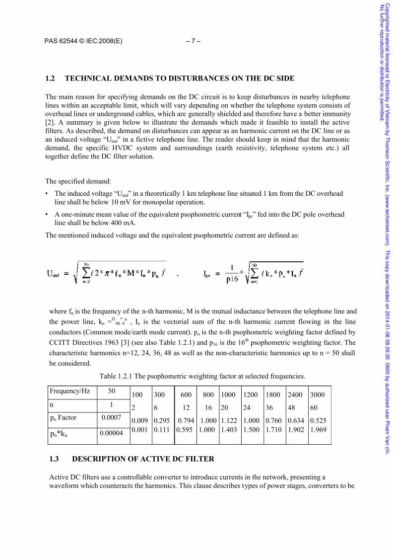
Figure 1.4.2 Impedance Characteristic of different passive filters
Assumedfrequencydeviation
SingleCapacitor
SingleTuned Filter
DoubleTuned Filter
0,0 Hz 6,7 kV 4,4 kV 2,8 kV
±0,1 Hz 6,7 kV 4,4 kV 2,8 kV
±1,0 Hz 6,8 kV 4,6 kV 3,1 kV
Table 1.4.1 Voltage to be supplied by the active partwith different selections of passive parts
The primary costs in the design of aconventional DC filter are the smoothing reactorand the main DC filter capacitor connected to theDC line. If one disregards the smoothing reactor,which costs the same or more than the maincapacitor, the cost of the main capacitor is
approximately 90 % of the totals, while thereactors, the low voltage capacitor and resistorshave small influence on the total cost.
The main difference between a conventional passive DC filter and the passive part in theactive filter is the lack of resistive elements inthe filter. The reason is that the control algorithmand VSC are able to compensate the frequencydeviation on the AC side of the HVDC converterand the component deviation. Hence it is notnecessary for the filter designer to optimise the
filter in that respect. When an active DC filter isused, the frequency deviation will change from a performance issue to a rating question on theVSC. In a recent project with long HVDC lines,resistive elements in the passive part of the DCfilter were inserted to reduce the resonance in theoverall system.
The DC capacitor will always be a part of theactive DC filter, connecting the active part withhigh voltage DC line. In future active DC filters, parts of the resonance circuit or the additional
components in the passive filter are expected to be replaced by larger power stages, since the price of the power stages decrease rapidly.
1.4.2 The current transducer
The function of the current transducer is to measure the line current. The Rogowski coil has been chosenas the current transducer in all known projects [12],[13]. To get a correct functioning of the active DCfilter, it is required to have at least one current transducer at each pole line in the station where the activeDC filter(s) is/are installed. The current transducer may be connected to the control through a light guide
(Figure 1.4.1) and is fed from a power supply which utilizes the harmonic current flowing in the filter, or by a photocell array at the sensor and a second light guide connected to the control equipment. Thefollowing data has to be taken into account when designing the transducer.
• A very high DC current through the current transducer. The DC current makes it difficult to use an ironcore transformer.
• The second harmonic current can be of considerable size (more than 10 Arms), where the harmonics atother frequencies is in the size of 10 mA, when the control is active.
• Some current transducers may need a power supply at the high voltage DC transmission level. Thecurrent transducer can be equipped with an electronic unit to communicate with ground levelequipment.
C o p y r i gh
t e d m
a t er i al l i c
en
s e d t oE l e
c t r i c i t y of V i e
t n am b
y T h
om
s on
S c i en
t i f i c ,I n
c
. ( www. t e
c h
s t r e e t . c om
) .T h i s
c o p y d ownl o
a d e d on2
0 1 4 - 0 1 - 0
6 0 8 : 2
6 : 3
0 - 0
6 0 0 b y a u t h or i z
e d u s er P h
am V
an
c h i .
N of ur t h
er r e
pr o
d u c t i on
or
d i s
t r i b u t i oni
s p er mi t t e
d .

7/25/2019 iecpas62544ed1.0en.pdf
http://slidepdf.com/reader/full/iecpas62544ed10enpdf 16/58
– 14 – PAS 62544 © IEC:2008(E)
• The current measurement with the analogue/digital conversion must be accurate within a largetemperature range from minimum ambient temperature with minimum load in the winter to maximumambient temperature with sun and a maximum load in the summer.
• The current transducer shall be able to measure the current with sufficient bandwidth (typically 1,5 to2 times the selected active range for the control) to secure a well-performing control in the activefrequency range (normally in the range 300 Hz to 3 000 Hz).
1.4.3 The control system
An A/D conversion is necessary before the signal from the current transducer enters the digital signal processors (DSP) and, in some installations, also a D/A conversion before the calculated signal from thecomputer enters the VSC. The duration of the control process from measured current on line to injectedcurrent on line adds a delay, which the control algorithm shall be able to handle. At high frequencies the phase shift will be considerable. The control will be further described in clause 1.5. To be able to controlthe VSC at frequencies up to 3,0 kHz, the computer or parts of the computer shall process complex taskswith a sample rate of at least 10 kHz. The control sample rate can be less, if the demand to the frequencyrange to control is reduced.
Although analog control circuits are theoretically possible, preference is given to digital computerassisted controls. The main reasons to choose digital computers are that they can supply the neededflexibility to the complexity of the overall system of control and easy adaptability to new controlalgorithms.
1.4.4 The amplifier
The voltage source converters in the first installed filters comprised a transformer and MosFET PWMamplifiers with a switching frequency at 66 kHz and a voltage of 330 V peak. They are able to maintainfull power (3 dB limit) in the frequency range 100 Hz up to 3 kHz. New water cooled IGBT PWMamplifiers with switching frequencies considerably lower than the MosFET amplifiers are expected to beused in all future projects. The IGBT PWM amplifiers are expected to have sufficient high switchingfrequency (at least 10 kHz), higher voltage and better power handling with lower losses.
When using switching devices, harmonic distortions in the PLC range (30 kHz – 500 kHz) outside theactive control range may be introduced. With the present active DC filter design, including a transformerand a passive filter working as a low-pass filter particularly for frequencies in the PLC range, thisdistortion is normally suppressed.
1.4.5 The Transformer
The transformer is used because the existing amplifiers, providing voltages in the range 300 V to 1 000 V,are not able to deliver the necessary voltage above 3 kV. Because the transformer provides not only thenecessary voltage, but also the galvanic separation between the main circuit of the HVDC plant, it will be
still necessary in the future. The transformer is designed to produce the required voltage and to present alow impedance, making a minimum impact on the original passive filter characteristic.
1.4.6 Protection circuit and arrester
The protection circuit measures the currents and voltages and hence ensures that the amplifier is notstressed. The protection circuit consists of two thyristors able to carry the full fault current coming fromthe main circuit. The thyristors can be fired from the voltage/current supervision as well as the ownsupervision of the amplifiers. The arrester limits the voltage across the transformer and amplifier.
Adequate protection of the amplifier or power stage is essential for active DC filter schemes and has toinclude a protection circuit to conduct the fault current past the amplifier.
C o p y r i gh
t e d m
a t er i al l i c
en
s e d t oE l e
c t r i c i t y of V i e
t n am b
y T h
om
s on
S c i en
t i f i c ,I n
c
. ( www. t e
c h
s t r e e t . c om
) .T h i s
c o p y d ownl o
a d e d on2
0 1 4 - 0 1 - 0
6 0 8 : 2
6 : 3
0 - 0
6 0 0 b y a u t h or i z
e d u s er P h
am V
an
c h i .
N of ur t h
er r e
pr o
d u c t i on
or
d i s
t r i b u t i oni
s p er mi t t e
d .

7/25/2019 iecpas62544ed1.0en.pdf
http://slidepdf.com/reader/full/iecpas62544ed10enpdf 17/58
PAS 62544 © IEC:2008(E) – 15 –
1.4.7 Bypass switch and disconnectors
The bypass switch and disconnectors are installed in all active DC filters and enable the operation of theHVDC link without using the active part. This feature makes it possible to work on the active partwithout taking the HVDC link out of operation.
1.5 ACTIVE DC FILTER CONTROL
The aim of an active DC filter control is to mitigate the harmonic currents on the pole line and/or theelectrode line current which are originated at the local HVDC converter station, so that the interferenceon telephone lines, adjacent to the HVDC lines may be brought within allowable limits. The active DCfilter creates virtually a low impedance path between the pole and electrode lines (or ground, dependingon the configuration of the system) at the chosen harmonic frequencies. In this way, the harmonics areguided through the DC filter and thereby prevented from entering the HVDC line, so that the disturbanceon the line is diminished.
Below are some of the items that meet an important part of the design specification of the active filter
control: • the required distortion level;
• the modes of operation of the HVDC transmission;
• the type of HVDC transmission;
• the number of terminals in the HVDC system;
• single active DC filter / multiple active DC filters;
• the control system must be able to recover from abnormal system conditions.
1.5.1 Active DC Filter Control methods Three basic different control principles are discussed in this section, namely, feedback control,feedforward control or a combination of the two methods.
1.5.1.1 Feedback control
Feedback control forms the core of existing active DC filters in HVDC applications [14, 15] - such asshown in Figure 1.5.1. This controller is not only able to practically eliminate the harmonic currents, butit also compensates for inaccuracies of both the current measuring device and the control parameters.
The basic feedback control scheme is illustrated as a block diagram in Figure 1.5.1. The functionality ofthe control has been proven, but the compromise between stability and response has to be considered.
The quantity Il is the measured harmonic current in the transmission line, Iconv is the disturbance currentfrom the HVDC converter and Ifilt is the compensation current from the active DC filter. The total linecurrent Iline is the sum of Iconv and Ifilt. The external process is the transfer function between the outputvoltage from the active DC filter control, ua, and the current Ifilt.
The controller of Figure 1.5.1 consists of four blocks. The first block filters the input signal, to limit itsfrequency contents to within the operational range of the active filter (typically 300 Hz – 3 000 Hz).
The second block identifies each individual harmonic and then refers it to a set of two orthogonal vectors(cos n*C0*t, sin n*C0*t - where the integer n corresponds to the harmonic order and CO to 2-7rf 0, and f 0represents the fundamental frequency). The block receives a synchronising signal derived from theconverter AC voltage to enable the controller to adapt to changes in the network frequency. Notch filters,
usually connected in parallel [4], may be used to isolate the individual harmonics.
C o p y r i gh
t e d m
a t er i al l i c
en
s e d t oE l e
c t r i c i t y of V i e
t n am b
y T h
om
s on
S c i en
t i f i c ,I n
c
. ( www. t e
c h
s t r e e t . c om
) .T h i s
c o p y d ownl o
a d e d on2
0 1 4 - 0 1 - 0
6 0 8 : 2
6 : 3
0 - 0
6 0 0 b y a u t h or i z
e d u s er P h
am V
an
c h i .
N of ur t h
er r e
pr o
d u c t i on
or
d i s
t r i b u t i oni
s p er mi t t e
d .

7/25/2019 iecpas62544ed1.0en.pdf
http://slidepdf.com/reader/full/iecpas62544ed10enpdf 18/58
– 16 – PAS 62544 © IEC:2008(E)
Figure 1.5.1 Basic control loop of an active DC filter
The third block performs the function of filter and PI controller. The block also compensates the external process at the harmonic frequency n*f 0. An example of a measured transfer function of the external process is shown in Figure 1.5.2.
The fourth block combines the output of the previous blocks into a signal with suitable amplitude, phaseand harmonic contents to form the compensating signal.
Figure 1.5.2 Measured transfer function of external system, Baltic Cable HVDC link
1.5.1.2 Feedforward control
Active filters are designed for the normal stable harmonic load currents and voltages generated in the
HVDC power circuit. In case of disturbance (voltage breakdown, AC filter switching, transformer
C o p y r i gh
t e d m
a t er i al l i c
en
s e d t oE l e
c t r i c i t y of V i e
t n am b
y T h
om
s on
S c i en
t i f i c ,I n
c
. ( www. t e
c h
s t r e e t . c om
) .T h i s
c o p y d ownl o
a d e d on2
0 1 4 - 0 1 - 0
6 0 8 : 2
6 : 3
0 - 0
6 0 0 b y a u t h or i z
e d u s er P h
am V
an
c h i .
N of ur t h
er r e
pr o
d u c t i on
or
d i s
t r i b u t i oni
s p er mi t t e
d .

7/25/2019 iecpas62544ed1.0en.pdf
http://slidepdf.com/reader/full/iecpas62544ed10enpdf 19/58
PAS 62544 © IEC:2008(E) – 17 –
energising, overload conditions, etc.) in the HVDC scheme, the load conditions can be too extreme for theactive filter; therefore the operation of the active filter has to be adapted or even blocked temporarily.Feedforward information (for example, the DC output voltage of the HVDC converter) to correct theactive filter control loops during and after the disturbance, is a great help to achieve optimal active filteroperation with a minimum of delay.
Contrary to the feedback control, the feedforward control is an open loop control system and does not
require a high gain as the feedback controller (Figure 1.5.3). Compared to feedback control, feedforwardcontrol results in a quicker corrective action and thus reduces the controller’s response time, but the useof feedforward alone is not sufficient to compensate the disturbances to required level. The feedforwardcontrol has not been used in any HVDC systems.
Figure 1.5.3 Feed Forward Control for the active DC filter
1.5.1.3 The combined control system using feedforward and feedback control
In the combined control system, the major control (feedforward control) mitigates the harmonics. Thefeedback controller then plays a supporting role by correcting loop errors that result from measurementsand changing networks. The stability of the active DC filter control, the dynamic specifications of theactive filter and the cost/availability of high bandwidth voltage measurement equipment are some of thefactors that will determine whether the combined controller will be used. It should be mentioned that the
combined feedback and feedforward control system will be considerably more complex than theconventional feedback control system and has not yet been used in any HVDC systems.
1.5.1.4 Control and supervision for the active DC filter
The active filter needs different control and supervision loops to ensure its proper function. The following points consider an outline of a possible controller that consists of two control/supervision loops.
• Primary controller. The harmonic contents of the line current are diminished using the injectionsource. In a HVDC system that has the active DC filters, one control algorithm for each pole in eachstation should be sufficient to mitigate the pole line harmonic currents.
• Harmonic supervision. A relevant criterion, for instance the severity of the interference caused by
C o p y r i gh
t e d m
a t er i al l i c
en
s e d t oE l e
c t r i c i t y of V i e
t n am b
y T h
om
s on
S c i en
t i f i c ,I n
c
. ( www. t e
c h
s t r e e t . c om
) .T h i s
c o p y d ownl o
a d e d on2
0 1 4 - 0 1 - 0
6 0 8 : 2
6 : 3
0 - 0
6 0 0 b y a u t h or i z
e d u s er P h
am V
an
c h i .
N of ur t h
er r e
pr o
d u c t i on
or
d i s
t r i b u t i oni
s p er mi t t e
d .

7/25/2019 iecpas62544ed1.0en.pdf
http://slidepdf.com/reader/full/iecpas62544ed10enpdf 20/58
– 18 – PAS 62544 © IEC:2008(E)
the harmonic, is used to identify the most troublesome harmonics. This is done at an interval ofapproximately 1 min. The harmonic supervision verifies if the primary control is workingsatisfactory.
1.5.1.5 Measurement systems
The following quantities can be measured for either control or supervising functions: • the pole line Iline and/or the electrode current Ielec, using a Rogowski coil or a DC current
transformer;
• the filter current (Ifilt);
• the HVDC converter current (Iconv);
• the HVDC converter voltage (Uconv);
• the active DC filter output voltage (Uactive);
• AC side frequencies.
1.6 PROJECT DESCRIPTIONS AND DC FILTER SOLUTIONS
Several active DC filters are in operation in HVDC schemes today. All of the installed active DC filtersfor HVDC applications have been manufactured by ABB Power Systems AB and by Siemens AG. Thisclause will describe the background of the installed active filters.
In 1991 a test installation of an active DC filter was in operation at the Lindome Converter Station [16].The first commercial active DC filter was installed at the Tjele Converter Station in the Skagerrak 3HVDC Intertie commissioned in 1993, the second active DC filter was installed at the Baltic CableHVDC Link commissioned in 1994. In the Chandrapur-Padghe HVDC Bipole Project two active DCfilters in each station were commissioned in 2001. In the Tian-Guang long distance HVDC project twoactive filters plus one spare active filter in each station were installed in 2001. One active filter each at both the Thailand and Malaysia sides of the EGAT-TNB HVDC Interconnector project were alsocommissioned in 2001.
1.6.1 Skagerrak 3 HVDC Intertie
The new pole 3 has approximately the capacity of the two existing poles. The design was not a single polesolution. To minimise the losses and the electrode current, the current on one of the existing poles wasreversed and the link with the three poles was operated as a hybrid bipole (Figure 1.6.1).
The Pole 1 and Pole 2 DC filters have been extended from just a capacitor to tuned filters to meet thechanges in the old poles and to be able to fulfil the demands in the specification. Active DC filter on Pole
3 is a passive double tuned 12/36 filter with an active part. The passive filter has two functions: To couplethe VSC to the 350 kV pole line and to work as a passive filter when the active part is not in operation.The pole 3 DC filter is coupled between the pole line and neutral bus.
The overall control strategy is to minimise the earth mode current, thus three current transducers areinstalled, one at each pole. Consequently the harmonic current on the pole 3 line shall only be zero when pole 3 is operated as a monopole.
The control algorithm of the active DC filter will work on whole multiples of the fundamental frequencyin the frequency domain 300 Hz – 3 000 Hz. The reason not to control lower frequencies is that the ratingof the VSC will increase manifold times. Furthermore when considering the psophometric weightingfactor in the overall disturbance, the contribution from lower harmonics is negligible.
C o p y r i gh
t e d m
a t er i al l i c
en
s e d t oE l e
c t r i c i t y of V i e
t n am b
y T h
om
s on
S c i en
t i f i c ,I n
c
. ( www. t e
c h
s t r e e t . c om
) .T h i s
c o p y d ownl o
a d e d on2
0 1 4 - 0 1 - 0
6 0 8 : 2
6 : 3
0 - 0
6 0 0 b y a u t h or i z
e d u s er P h
am V
an
c h i .
N of ur t h
er r e
pr o
d u c t i on
or
d i s
t r i b u t i oni
s p er mi t t e
d .

7/25/2019 iecpas62544ed1.0en.pdf
http://slidepdf.com/reader/full/iecpas62544ed10enpdf 21/58
PAS 62544 © IEC:2008(E) – 19 –
Figure 1.6.1 Simplified diagram, showing active filter connection
The active DC filter in Skagerrak replaces one additional passive filter branch compared to a purely
passive solution.
1.6.2 Baltic Cable HVDC Link
The active DC filter is a passive double tuned 12/24 filter with an active part, located at the Krusebergstation at the Swedish side. Since no overhead line is present at the German side, no DC filter wasinstalled in Germany. The passive filter couples the active part to the 450 kV DC pole line. The tuning ofthe passive filter is chosen to minimise the rating of the active part. The active DC filter is coupled fromthe pole line to earth (Figure 1.6.2).
The control strategy is to minimise the DC pole line current harmonics coming from Kruseberg (theSwedish station) and from Herrenwyck (the German station). The control algorithm of the active DCfilter works on whole multiples of the fundamental frequency in the frequency domain 300 Hz –3 000 Hz. Since no DC filter is installed in Herrenwyck, the harmonics 600 Hz and 1 200 Hz currentscoming through the cable are especially significant, therefore the controller has to mitigate these currentsas well.
The active filter solution in Baltic cable replaces one additional passive filter branch and one smoothingreactor placed on the line side of the passive filter branches in Kruseberg. If only shunt filters were used,filters in both stations had to be installed. Due to the low impedance of the DC line and cable seen fromKruseberg the number of filter branches would be impractical and definitely not economical.
C o p y r i gh
t e d m
a t er i al l i c
en
s e d t oE l e
c t r i c i t y of V i e
t n am b
y T h
om
s on
S c i en
t i f i c ,I n
c
. ( www. t e
c h
s t r e e t . c om
) .T h i s
c o p y d ownl o
a d e d on2
0 1 4 - 0 1 - 0
6 0 8 : 2
6 : 3
0 - 0
6 0 0 b y a u t h or i z
e d u s er P h
am V
an
c h i .
N of ur t h
er r e
pr o
d u c t i on
or
d i s
t r i b u t i oni
s p er mi t t e
d .

7/25/2019 iecpas62544ed1.0en.pdf
http://slidepdf.com/reader/full/iecpas62544ed10enpdf 22/58
– 20 – PAS 62544 © IEC:2008(E)
Figure 1.6.2 Simplified diagram, showing active filter connection
1.6.3 Chandrapur-Padghe HVDC power transmission project
The DC filter is a passive double tuned 2/6 filter and passive double tuned high-pass 12/24 filter with anactive part. The 2/6 filter is necessary due to resonance with the DC line. Four active filters will beinstalled and each active DC filter is connected from the pole line to neutral bus (Figure 1.6.3).
The control strategy is to minimise earth mode current. The active DC filters works on whole multiples ofthe fundamental frequency in the frequency range 350 Hz – 2 500 Hz. The project was the first projectwith four active filters co-operating in one transmission.
The active filter solution in Chandrapur-Padghe replaces one additional passive filter branch in each poleand station compared to a purely passive solution.
Figure 1.6.3 Simplified diagram, showing active filter connection
C o p y r i gh
t e d m
a t er i al l i c
en
s e d t oE l e
c t r i c i t y of V i e
t n am b
y T h
om
s on
S c i en
t i f i c ,I n
c
. ( www. t e
c h
s t r e e t . c om
) .T h i s
c o p y d ownl o
a d e d on2
0 1 4 - 0 1 - 0
6 0 8 : 2
6 : 3
0 - 0
6 0 0 b y a u t h or i z
e d u s er P h
am V
an
c h i .
N of ur t h
er r e
pr o
d u c t i on
or
d i s
t r i b u t i oni
s p er mi t t e
d .

7/25/2019 iecpas62544ed1.0en.pdf
http://slidepdf.com/reader/full/iecpas62544ed10enpdf 23/58
PAS 62544 © IEC:2008(E) – 21 –
1.6.4 Tian - Guang long distance HVDC project
Each terminal station is provided with a DC filter scheme as shown in Figure 1.6.4. The DC filterconsists of a passive part with a double tuned 12/24 filter with damping resistor and an active part. Ateach station a spare DC filter is installed, able by means of disconnectors to replace the DC filter ateither pole. Six active filters are thus installed with four DC filter in continuous operation.
The control objective is to mitigate the harmonics in both lines.
The current transducers are Rogowski coils, but contrary to the previous current transducers, theelectronics are powered by light guides directly from the control equipment.
The active filter solution in the Tian - Guang HVDC project replaces one additional passive filter branch in each pole and station and reduces the size of the smoothing reactor compared to a purely passive solution.
Figure 1.6.4 Simplified diagram, showing active filter connection
1.6.5 EGAT-TNB (Thailand-Malaysia) HVDC Interconnection
Each terminal station is provided with a DC filter scheme as shown in Figure 1.6.5. The DC filterconsists of a passive part with a double tuned 12/24 filter without damping resistors and an active part.The control objective is to mitigate the harmonics in the line conductor connected to the smoothingreactor.
At its first stage, the interconnection operates as a monopolar metallic return scheme, where either line pole 1 or 2 can be used as an HV conductor. The current transducers are Rogowski coils with lightguide powered electronics. The proper current signal is automatically selected according to the
operation mode of the line.
C o p y r i gh
t e d m
a t er i al l i c
en
s e d t oE l e
c t r i c i t y of V i e
t n am b
y T h
om
s on
S c i en
t i f i c ,I n
c
. ( www. t e
c h
s t r e e t . c om
) .T h i s
c o p y d ownl o
a d e d on2
0 1 4 - 0 1 - 0
6 0 8 : 2
6 : 3
0 - 0
6 0 0 b y a u t h or i z
e d u s er P h
am V
an
c h i .
N of ur t h
er r e
pr o
d u c t i on
or
d i s
t r i b u t i oni
s p er mi t t e
d .

7/25/2019 iecpas62544ed1.0en.pdf
http://slidepdf.com/reader/full/iecpas62544ed10enpdf 24/58
– 22 – PAS 62544 © IEC:2008(E)
The active filter solution in the EGAT-TNB HVDC Interconnection replaces one additional passivefilter branch in each station and reduces the size of the smoothing reactor compared to a purely passivesolution.
Figure 1.6.5 Simplified diagram, showing active filter connection
1.7 PERFORMANCE OF THE SKAGERRAK 3 HVDC INTERTIE ACTIVE DC
FILTER
To illustrate the performance of the active DC filter, a pole line current was measured in the Skagerrak 3HVDC Intertie. Pole 3 was operated as monopole and the transmitted power level was 240 MW. The
pole line current with and without the active part is shown in Figure 1.7.1. The first current spectrumshows the line current with the active part not in operation and the second spectrum shows the linecurrent with the active part in operation.
C o p y r i gh
t e d m
a t er i al l i c
en
s e d t oE l e
c t r i c i t y of V i e
t n am b
y T h
om
s on
S c i en
t i f i c ,I n
c
. ( www. t e
c h
s t r e e t . c om
) .T h i s
c o p y d ownl o
a d e d on2
0 1 4 - 0 1 - 0
6 0 8 : 2
6 : 3
0 - 0
6 0 0 b y a u t h or i z
e d u s er P h
am V
an
c h i .
N of ur t h
er r e
pr o
d u c t i on
or
d i s
t r i b u t i oni
s p er mi t t e
d .

7/25/2019 iecpas62544ed1.0en.pdf
http://slidepdf.com/reader/full/iecpas62544ed10enpdf 25/58
PAS 62544 © IEC:2008(E) – 23 –
Figure 1.7.1 Measured line current spectra, pole 3 operated as monopole.
The psophometric current (see Clause 2)
Figure 1.7.1, was reduced from 4780 mA to 255 mA. The major harmonic line currents are shown in
Table 1.7.1.
Table 1.7.1 Major harmonic line currents, pole 3 operated as monopole
Frequency No active filtering Active filtering
[Hz]
Weight factor pn*k n
Current
[Arms]
WeightedCurrent [Arms]
Current
[Arms]
WeightedCurrent [Arms]
300 0.111 3.668 0.406 0.0881 0.0097
600 0.595 0.844 0.503 0.0180 0.0107
1200 1.500 0.836 1.253 0.0245 0.0368
1800 1.710 2.216 3.788 0.0436 0.0746
2400 1.902 0.350 0.675 0.0253 0.0488
2700 1.957 0.338 0.662 0.0217 0.0424
3000 1.969 1.164 2.292 0.0242 0.0477
C o p y r i gh
t e d m
a t er i al l i c
en
s e d t oE l e
c t r i c i t y of V i e
t n am b
y T h
om
s on
S c i en
t i f i c ,I n
c
. ( www. t e
c h
s t r e e t . c om
) .T h i s
c o p y d ownl o
a d e d on2
0 1 4 - 0 1 - 0
6 0 8 : 2
6 : 3
0 - 0
6 0 0 b y a u t h or i z
e d u s er P h
am V
an
c h i .
N of ur t h
er r e
pr o
d u c t i on
or
d i s
t r i b u t i oni
s p er mi t t e
d .

7/25/2019 iecpas62544ed1.0en.pdf
http://slidepdf.com/reader/full/iecpas62544ed10enpdf 26/58
– 24 – PAS 62544 © IEC:2008(E)
1.8 CONCLUSIONS ON ACTIVE DC FILTERS
• The need for active DC filters is a consequence of stringent demand on telephone systems. Furtherintroduction of digital and optical systems can reduce these requirements.
• Series connections of active filters in the main HVDC circuit are conceivable, but some basic problems have to be solved before the solution becomes recommendable.
• All active DC filters implemented today and in the near future will be connected as a hybrid filter,where the passive filter is used to connect the active part with the high voltage DC line.
• The type most suited to power stage applications, particularly high power, is the voltage sourceconverter.
• The relative high frequencies for active filtering exclude thyristors and GTO. Consequently MosFETand IGBT are used in voltage source converters.
• Although analog control circuit in theory is possible, digital computer assisted controls are preferred.
• All control systems in existing and expected systems with active DC filters use feedback control, butfeedforward control or a combination might be a future option.
• Adequate protection of the voltage source converter is essential for active DC filter schemes.
C o p y r i gh
t e d m
a t er i al l i c
en
s e d t oE l e
c t r i c i t y of V i e
t n am b
y T h
om
s on
S c i en
t i f i c ,I n
c
. ( www. t e
c h
s t r e e t . c om
) .T h i s
c o p y d ownl o
a d e d on2
0 1 4 - 0 1 - 0
6 0 8 : 2
6 : 3
0 - 0
6 0 0 b y a u t h or i z
e d u s er P h
am V
an
c h i .
N of ur t h
er r e
pr o
d u c t i on
or
d i s
t r i b u t i oni
s p er mi t t e
d .

7/25/2019 iecpas62544ed1.0en.pdf
http://slidepdf.com/reader/full/iecpas62544ed10enpdf 27/58
PAS 62544 © IEC:2008(E) – 25 –
2 ACTIVE AC FILTERS IN HVDC APPLICATIONS
2.1 INTRODUCING ACTIVE AC FILTERS
Non-linear loads and sources cause voltage distortion of the sine wave in electrical distribution andtransmission networks. The primary sources of electrical energy, synchronous generators or over-synchronous running asynchronous generators, produce nearly undistorted sine waves.
Classical loads such as uncontrolled motors, heaters and incandescent lamps connected to a sinusoidalsource will take nearly undistorted currents. This is in contrast to fluorescent lamps, controlled motordrives, computers and TV sets. Most of the distortion in LV and MV distribution networks is caused bysuch loads, and may even be propagated into HV networks. In particular the 5 th harmonic is of greatconcern for the utilities, particularly during the evening hours. The increasing non-linear loads over thelast ten years are topic of many conferences on power quality.
For larger loads such as traction rectifiers, 12 pulse instead of 6 pulse operation shifts the distortion to the11th and 13th harmonics. Sometimes passive filters in single or double tuned configurations are used. Thesefilters are less effective for distributed loads and non-characteristic harmonics.
HVDC converters feeding into an existing HVAC network are a source of distortion themselves. Fromthe beginning of the HVDC transmission, these problems have been recognised and passive filters for the11/13th and 23/25th harmonics are applied in all existing schemes. The filters also contribute to thecompensation of the inductive character of the rectifier and inverter.
The interest in active power filters has grown over a number of years due to more stringent requirementsand guidelines placed on customers and supply utilities such as the IEEE 519 or IEC 61000 series. These place maximum limits on various current and voltage harmonics generated and drawn at the point ofcommon coupling (PCC). Requirements to develop low-cost and robust active filters with multifunctionalcontrol capabilities, such as sag and dip compensation has emerged from industry. The developments in
active power filters have also motivated their application for HVDC, on the AC, DC or both sides of theHVDC converter [20],[21],[22],[23].
In contrast to passive filters designed to operate at distinct frequencies, active filters can cover a range offrequencies, including non-characteristic harmonics. Active filters for the HVDC side are already inoperation and have been studied by our WG recently [24]. The power requirements for the HVAC sidemay be considerably higher. Only one plant is under operation at the AC side of an HVDC converterstation, as a pilot project, and it is also described in this report.
For tutorial reasons, LV and MV applications of active filters with different control schemes are alsodiscussed briefly .
2.2 TECHNICAL DEMANDS TO HARMONIC DISTURBANCES ON THE AC SIDE
Many loads produce harmonics at low and medium voltage networks. Fluorescent tubes and lamps aswell as computers and other electronic devices generate harmonics. For the low and medium voltage, thegrid owner may need to install filters at the distribution bus if the voltage distortion caused by all smallharmonic sources in the system, is unacceptable. When connecting HVDC converter stations or largeloads to the AC system that generate harmonics, such as industrial rectifiers, large motor drives andelectrical arc furnace plants, AC filters are usually installed as a part of these loads or the HVDC systemin order to ensure that the injection of harmonics into the AC system is limited to acceptable levels.
C o p y r i gh
t e d m
a t er i al l i c
en
s e d t oE l e
c t r i c i t y of V i e
t n am b
y T h
om
s on
S c i en
t i f i c ,I n
c
. ( www. t e
c h
s t r e e t . c om
) .T h i s
c o p y d ownl o
a d e d on2
0 1 4 - 0 1 - 0
6 0 8 : 2
6 : 3
0 - 0
6 0 0 b y a u t h or i z
e d u s er P h
am V
an
c h i .
N of ur t h
er r e
pr o
d u c t i on
or
d i s
t r i b u t i oni
s p er mi t t e
d .

7/25/2019 iecpas62544ed1.0en.pdf
http://slidepdf.com/reader/full/iecpas62544ed10enpdf 28/58
– 26 – PAS 62544 © IEC:2008(E)
Filtering is required due to the following effects of harmonics:
– Additional stresses The waveform distortion causes losses, resulting in additional heating, and stresses in boththe customer's and the utility's equipment.
– Maloperation of electronic equipment
Also the harmonics may cause maloperation of electronic equipment and protective equipment, e.g. protection relays.
– Telecommunication system disturbance In the case of overhead lines with nearby telecommunication lines, the harmonics may interfere withthe telecommunication via inductive couplings between the two systems. Even the induced voltages intelecommunication and other low voltage system caused by harmonics flowing in the AC systemmay result in voltages higher than the regulations permit with respect to human safety.
A discussion on the permissible distortion limits is included in the report "Guide to the Specification andDesign Evaluation of AC Filters for HVDC Systems" by the WG 14.30 [25]. Some typical values areconsidered in the item 1.12.5 of the present report.
2.3 PASSIVE FILTERS
2.3.1 Conventional passive filters
Traditionally, the filters installed in large harmonic generatingloads have been of the passive type, usually designed as shuntelements creating a low impedance path for the harmonics to befiltered. The filter is build up as a resonant circuit consisting ofcapacitor(s) and inductor(s), and in most cases also resistor(s) for
giving the filter a more 'soft' damped characteristic. Usually the passive filters are tuned to one frequency only (single-tuned filter),to two frequencies (double-tuned filter) or even to threefrequencies (triple-tuned filter). Variations in frequency andtemperature, causing impedance variation of the filters (detuning),in most cases result in the need for damping resistors in the filter inorder to make the characteristics more 'soft'. The introduction ofthe damping resistor makes the filtering performance at tuningfrequency less effective, however a wider frequency range can befiltered and hence the frequency variations are coped with.
The reduced filtering efficiency caused by the resistor may lead to a
need for larger filters or installation of more parallel filter banks. The design of passive filters is highlydependent on the connected harmonic impedance of the network. It is vital that critical resonances between network and filter are avoided. In order to obtain an adequate passive filter design, detailedstudies are required to be performed.
A typical double-tuned filter is shown in Figure 1.3.1.
In Cigré technical brochure no. 139 [25], passive AC filters for HVDC systems are described anddiscussed in detail.
Figure 1.3.1: Conventional doubletuned passive filterwith damping resistor
C o p y r i gh
t e d m
a t er i al l i c
en
s e d t oE l e
c t r i c i t y of V i e
t n am b
y T h
om
s on
S c i en
t i f i c ,I n
c
. ( www. t e
c h
s t r e e t . c om
) .T h i s
c o p y d ownl o
a d e d on2
0 1 4 - 0 1 - 0
6 0 8 : 2
6 : 3
0 - 0
6 0 0 b y a u t h or i z
e d u s er P h
am V
an
c h i .
N of ur t h
er r e
pr o
d u c t i on
or
d i s
t r i b u t i oni
s p er mi t t e
d .

7/25/2019 iecpas62544ed1.0en.pdf
http://slidepdf.com/reader/full/iecpas62544ed10enpdf 29/58
PAS 62544 © IEC:2008(E) – 27 –
With high demand on filter efficiency, it may be difficult to maintain the reactive power balance with theAC system and at the same time meet the filtering requirements. In this case more sophisticated solutionsshould be applied, such as continuously tuned filters, active filters or hybrid filters.
2.3.2 Continuously tuned passive filters
2.3.2.1 Introduction
As mentioned above, conventional bandpass filters (forexample, 11th and 13th) have to be equipped withdamping resistors for giving a broad bandcharacteristic to allow them to cope with the frequencyvariations of the AC network and the variations incomponent values due to temperature changes.Consequently, filtering at high harmonic levels mayrequire a number oflarge harmonic filter banks.
Figure 1.3.2 shows a continuously tuned filter. Acontinuously tuned AC filter is always tuned to theharmonic frequency (e.g. 11th or 13th) and has a high Q-factor, thus giving high performance and low losses. Inthe continuously tuned filter, the tuning frequency isautomatically adjusted to provide perfect tuningirrespective of frequency excursions and componentvariations. The filters therefore need no additionaldamping resistor. The perfect tuning is achieved byvariations of the inductance of the filter reactor. Just one
continuously tuned filter is sufficient to provide therequired filtering for a particular harmonic.
2.3.2.2 Filter reactor with variable
inductance
No physically moving parts are needed for changing theinductance. An iron core is placed in the centre of thereactor. Around the iron core there is a control winding,see Figure 1.3.4. By feeding direct current into thecontrol winding, the total magnetic flux in the reactor isinfluenced, thereby changing the inductance. The
linearity of the rate of change of inductance with respectto the control current is high, which simplifies designingto avoid instability in tuning control.
2.3.2.3 Automatic tuning control
The schematic overview of the continuously tuned filter isshown in Figure 1.3.3.
The AC bus harmonic voltage and the filter harmonic current are measured and the phase angle α,
Figure 1.3.2:Continuously tuned filter
Figure 1.3.3:Schematic overview of continuously tuned filter
Figure 1.3.4: Principal overview of a filter reactor
with variable
C o p y r i gh
t e d m
a t er i al l i c
en
s e d t oE l e
c t r i c i t y of V i e
t n am b
y T h
om
s on
S c i en
t i f i c ,I n
c
. ( www. t e
c h
s t r e e t . c om
) .T h i s
c o p y d ownl o
a d e d on2
0 1 4 - 0 1 - 0
6 0 8 : 2
6 : 3
0 - 0
6 0 0 b y a u t h or i z
e d u s er P h
am V
an
c h i .
N of ur t h
er r e
pr o
d u c t i on
or
d i s
t r i b u t i oni
s p er mi t t e
d .

7/25/2019 iecpas62544ed1.0en.pdf
http://slidepdf.com/reader/full/iecpas62544ed10enpdf 30/58
– 28 – PAS 62544 © IEC:2008(E)
calculated. The direct control current fed through the control winding is then adjusted to achieve zero phase shift between the voltage and current of the particular harmonic. This is the criterion for perfecttuning of the filter.
2.3.2.4 Existing continuously tuned filter installations
A prototype 11th harmonic ConTune AC filter (ConTune: is a trade mark for ABB's continuously tunedfilter) has been in operation at the Lindome station of the Konti-Skan HVDC link since December 1993.The operation experience from this has been very good.
A commercial 11th filter is in operation at Celilo station of the Pacific Intertie HVDC transmission.
A filter scheme consisting of 11th and 13th ConTune and 24th and 36th conventional high-pass filters isinstalled for the 600 MW SwePol cable transmission with conventional HVDC converters (see also1.12.2.1). Capacitor banks provide the reactive power balance.
A filter scheme with 11th and 13th ConTune and 24th and 36th conventional high pass filters is installed for2x550 MW Brazil-Argentina Interconnection (Garabi back-to-back station) – see also 1.12.2.2. Thereactive power balance is provided by series capacitors.
2.4 REASONS FOR USING ACTIVE FILTERS IN HVDC SCHEMES
Unlike passive filters, where the harmonic reduction depends on the combination of filter impedance andnetwork impedance, active filters use power electronics to produce a voltage or a current with the properwaveform to mitigate selected harmonics or harmonics inside a given frequency range.
The active filter output has to present all selected harmonics, each one with the amplitude and phase thatare required to counteract the harmonic sources. To get this, voltages and/or currents are measured in theHVDC station and processed by a suitable control equipment using signal processing techniques. AnIGBT converter (see 1.7, "Converter configurations") produces the necessary voltages or currents asdetermined by the control equipment. For HV applications, like HVDC, the active filter will be generallyconnected to the network through a passive filter, thus building a hybrid filter scheme.
Due to its nature, active filters present the following characteristics:
• High effectiveness. The harmonics can be mitigated effectively, even if the network impedance is verylow at the harmonic frequencies.
• One active filter alone can mitigate several harmonics simultaneously. This results in smaller placerequirements and simpler filter arrangements in comparison to passive filter solutions.
• In contrast to passive filters, active filters do not introduce any resonance with the network. Thisresults from the fact that active filters reduce each particular harmonic just by injecting a
controlled voltage or current with the frequency of that harmonic. • Active filters do not add reactive power to the network, by the same reason as in the last point.
• Elimination of existing resonance effects. This is achieved through the cancellation of the harmonic voltage on the filter busbar or harmoniccurrent in the lines. Another control method was presented in [22].
• Flexibility for changing frequency characteristics within derated capability. Changes, such as selection of harmonics to be filtered, can be made just by settings in the software.
• Self-adaptation to changes in the network frequency.
• Self-adaptation to changes in the network harmonic impedance. Self-tuning control algorithms can
C o p y r i gh
t e d m
a t er i al l i c
en
s e d t oE l e
c t r i c i t y of V i e
t n am b
y T h
om
s on
S c i en
t i f i c ,I n
c
. ( www. t e
c h
s t r e e t . c om
) .T h i s
c o p y d ownl o
a d e d on2
0 1 4 - 0 1 - 0
6 0 8 : 2
6 : 3
0 - 0
6 0 0 b y a u t h or i z
e d u s er P h
am V
an
c h i .
N of ur t h
er r e
pr o
d u c t i on
or
d i s
t r i b u t i oni
s p er mi t t e
d .

7/25/2019 iecpas62544ed1.0en.pdf
http://slidepdf.com/reader/full/iecpas62544ed10enpdf 31/58
PAS 62544 © IEC:2008(E) – 29 –
extend this characteristic, so that the necessary performance is reached even though the harmonicimpedance of the network varies over a wide range.
• The characteristic of the same active filter can be optimised for harmonic voltage (e.g. total harmonicdistortion THD, Telephone Harmonic Form Factor THFF, telephone interference factor TIF ) orharmonic current (e.g. IT product, equivalent disturbing current), depending on the measured
magnitudes and control settings. The active filter may be connected to the network through a comparatively small passive filter, which can be switched on before starting the HVDC converter and then stay permanently in service. Thiscombination between active and passive filters is called a hybrid filter. The additional demand on reactive power is than covered by capacitor banks and eventually few passive filters.
The use of hybrid filters in HVDC schemes could be considered due to the above listed reasons. Somecases where these filters should be considered:
• very small harmonic distortion levels are envisaged;
• the reactive power compensation can be performed with less filters than the amount of passivefilters required for harmonic elimination;
• a passive filter solution gets complex due to resonance with the network;
• other harmonic sources in the network have to be regarded and a current-optimised filter solution is preferred (rather than a voltage-optimised solution);
• In the series compensated HVDC schemes (Capacitor Commutated Converter CCC, ControlledSeries Capacitor Converter CSCC);
• When an existing filter installation could be up-graded by adding an active part (due to moreharmonics, resonance problems, etc.).
Important advantages of using such hybrid filters are:
• the performance is not reduced either in case of variation of network frequency or in case ofvariations in the associated passive filter due to temperature or failures in capacitor cells (whichcauses detuning of the passive filter);
• damping resistors can be avoided at the associated passive filter, as the active filter covers the wholespecified frequency range and is not affected by "detuning";
• smaller amount of filters in comparison to a passive filter solution by the above mentioned reason.
2.5 OPERATION PRINCIPLES OF ACTIVE FILTERS
2.5.1 Shunt connected active filter
The most common configuration is the shunt connection, where the active filter is connected in parallelwith the AC network and provided with a current control.
The active filter constantly injects harmonic currents in opposition to the harmonic currents generated bythe load. These harmonic currents compensate each other and the result is that the current supplied by the power source remains sinusoidal.
C o p y r i gh
t e d m
a t er i al l i c
en
s e d t oE l e
c t r i c i t y of V i e
t n am b
y T h
om
s on
S c i en
t i f i c ,I n
c
. ( www. t e
c h
s t r e e t . c om
) .T h i s
c o p y d ownl o
a d e d on2
0 1 4 - 0 1 - 0
6 0 8 : 2
6 : 3
0 - 0
6 0 0 b y a u t h or i z
e d u s er P h
am V
an
c h i .
N of ur t h
er r e
pr o
d u c t i on
or
d i s
t r i b u t i oni
s p er mi t t e
d .

7/25/2019 iecpas62544ed1.0en.pdf
http://slidepdf.com/reader/full/iecpas62544ed10enpdf 32/58
– 30 – PAS 62544 © IEC:2008(E)
Figure 1.5.2: Example of current waves
- top, solid line: Load current current Il - top, dotted line: resulting source current Is - bottom: compensating filter current If
The active filter needs to be sized only for the harmonic currents, generated by the non-linear load and notfor the full load current. For higher voltages than the voltage level of the active part, a couplingtransformer will be used.
2.5.2 Series connected active filter
This type of filter, connected in series with the line, is mainly aimed at reducing the voltage distortionalready present on the AC system and applied to the load. It acts as a "harmonic isolator" device.Associated with a passive filter, it can also reduce the harmonic currents generated by the load (see hybrid
configurations).
Figure 1.5.1: Shunt connection
C o p y r i gh
t e d m
a t er i al l i c
en
s e d t oE l e
c t r i c i t y of V i e
t n am b
y T h
om
s on
S c i en
t i f i c ,I n
c
. ( www. t e
c h
s t r e e t . c om
) .T h i s
c o p y d ownl o
a d e d on2
0 1 4 - 0 1 - 0
6 0 8 : 2
6 : 3
0 - 0
6 0 0 b y a u t h or i z
e d u s er P h
am V
an
c h i .
N of ur t h
er r e
pr o
d u c t i on
or
d i s
t r i b u t i oni
s p er mi t t e
d .

7/25/2019 iecpas62544ed1.0en.pdf
http://slidepdf.com/reader/full/iecpas62544ed10enpdf 33/58
PAS 62544 © IEC:2008(E) – 31 –
The connection of the active filter to the supply is made through a coupling transformer, which must besized for the total load current rating and injected series voltage U f . The current through the active filtershould be designed for the transformed load current as well.
Figure 1.5.3: Series connection
2.6 PARALLEL AND SERIES CONFIGURATION
In some cases, the combined features of parallel and series configurations may be needed at one location.
A DC link between the two active filters may be used for transfer of active power between the activefilters.
Figure 1.6.1: Series and parallel connection
C o p y r i gh
t e d m
a t er i al l i c
en
s e d t oE l e
c t r i c i t y of V i e
t n am b
y T h
om
s on
S c i en
t i f i c ,I n
c
. ( www. t e
c h
s t r e e t . c om
) .T h i s
c o p y d ownl o
a d e d on2
0 1 4 - 0 1 - 0
6 0 8 : 2
6 : 3
0 - 0
6 0 0 b y a u t h or i z
e d u s er P h
am V
an
c h i .
N of ur t h
er r e
pr o
d u c t i on
or
d i s
t r i b u t i oni
s p er mi t t e
d .

7/25/2019 iecpas62544ed1.0en.pdf
http://slidepdf.com/reader/full/iecpas62544ed10enpdf 34/58
– 32 – PAS 62544 © IEC:2008(E)
The following table summarises the preferred configurations depending on the origin of the harmonicdistortion (load or source side) considering common LV and MV applications.
Table 1.6.1: Preferred topologies for common LV and MV applications
Load Source
Non-distorting Distorting
Non-distorted - Shunt
Distorted Series Shunt +
Series
2.6.1 Hybrid filter schemes
This solution, combining an active filter and a passive filter, may be either of the series or parallel type.
An example of parallel combination, which is feasible for low and medium voltage systems, is presentedin Figure 1.6.2. For high voltage applications, a hybrid filter built up by the combination of a passive andan active filter in series is required. Such a hybrid configuration is further discussed in 1.8.3.
In the example of Figure 1.6.2, the passive filter may carry out basic filtering of the predominantharmonic (generally, the 5th in low and medium voltage systems), while the active filter, due to its limitedrating, covers the other harmonics.
This configuration gives better performances than a passive filter alone, at a lower cost than with a purelyactive filter. This association is a technical and economical compromise solution when high performancesare required.
Figure 1.6.2: Hybrid configuration
C o p y r i gh
t e d m
a t er i al l i c
en
s e d t oE l e
c t r i c i t y of V i e
t n am b
y T h
om
s on
S c i en
t i f i c ,I n
c
. ( www. t e
c h
s t r e e t . c om
) .T h i s
c o p y d ownl o
a d e d on2
0 1 4 - 0 1 - 0
6 0 8 : 2
6 : 3
0 - 0
6 0 0 b y a u t h or i z
e d u s er P h
am V
an
c h i .
N of ur t h
er r e
pr o
d u c t i on
or
d i s
t r i b u t i oni
s p er mi t t e
d .

7/25/2019 iecpas62544ed1.0en.pdf
http://slidepdf.com/reader/full/iecpas62544ed10enpdf 35/58
PAS 62544 © IEC:2008(E) – 33 –
2.7 CONVERTER CONFIGURATIONS
2.7.1 Converters
Basically, two types of converters can be used in active AC filters, the voltage-source converter and thecurrent-source converter. In both cases, the converter can present a three-phase (three or four wire type)or a single-phase structure.
2.7.1.1 Current-source converter
This kind of converter has an inductor as the energy storage component. The use of this configuration islimited due to the coil and additional semiconductor losses.
Figure 1.7.1: Three-phase current-source converter
2.7.1.2 Voltage-source converter
This is the preferred configuration, because it is the most cost-effective. Almost all active filters, whichhave been put into operation, have adopted the voltage-fed PWM inverter structure.
Figure 1.7.2: Three-phase 2-level voltage-source converter (three-wire type).
C o p y r i gh
t e d m
a t er i al l i c
en
s e d t oE l e
c t r i c i t y of V i e
t n am b
y T h
om
s on
S c i en
t i f i c ,I n
c
. ( www. t e
c h
s t r e e t . c om
) .T h i s
c o p y d ownl o
a d e d on2
0 1 4 - 0 1 - 0
6 0 8 : 2
6 : 3
0 - 0
6 0 0 b y a u t h or i z
e d u s er P h
am V
an
c h i .
N of ur t h
er r e
pr o
d u c t i on
or
d i s
t r i b u t i oni
s p er mi t t e
d .

7/25/2019 iecpas62544ed1.0en.pdf
http://slidepdf.com/reader/full/iecpas62544ed10enpdf 36/58
– 34 – PAS 62544 © IEC:2008(E)
The neutrally clamped 3-level converter is used to minimize the losses or to increase power handlingcapability. This topology can also compensate unbalanced currents.
Figure 1.7.3: Three-phase 3-level voltage-source converter (three-wire type).
2.7.1.3 Single-phase voltage-source converter Single phase active filters are based on a single phase voltage source bridges shown below. Althoughthree-phase converters have been used for most low and medium voltage applications, three separatesingle-phase converters can be used in the three-phase active filter applications also.
Figure 1.7.4: Single-phase voltage source converter
C o p y r i gh
t e d m
a t er i al l i c
en
s e d t oE l e
c t r i c i t y of V i e
t n am b
y T h
om
s on
S c i en
t i f i c ,I n
c
. ( www. t e
c h
s t r e e t . c om
) .T h i s
c o p y d ownl o
a d e d on2
0 1 4 - 0 1 - 0
6 0 8 : 2
6 : 3
0 - 0
6 0 0 b y a u t h or i z
e d u s er P h
am V
an
c h i .
N of ur t h
er r e
pr o
d u c t i on
or
d i s
t r i b u t i oni
s p er mi t t e
d .

7/25/2019 iecpas62544ed1.0en.pdf
http://slidepdf.com/reader/full/iecpas62544ed10enpdf 37/58
PAS 62544 © IEC:2008(E) – 35 –
2.7.2 STATCOM
The term STATCOM (Static Synchronous Compensator) stands for a device using GTOs , IGCT(Integrated Gate Commutated Thyristor) or IGBT to produce reactive power at the network frequency.WG14-19 has prepared a full document on STATCOM principles and applications [26].
This section presents basic principles of the STATCOM and explains how it can be conceived to
incorporate active filter features. The STATCOM can also be used as active filter, if the device is fastenough (either a high switching frequency or multi-levels or a combination).
2.7.2.1 STATCOM principles
The principle behind the operation of a STATCOM is very simple; it depends on the idea of twogenerators connected together by an inductor. For the case in question one generator is the power system,while the other is the STATCOM. The operation can be divided into five sections:
1 - The system and the STATCOM have the same amplitude and phase, so under this condition no current flows in the inductor and the STATCOM is operating at "float".
2 - The system voltage is higher than the STATCOM voltage, but the phase shift is still zero. A voltage now appears across the inductor, in phase with the system voltage. Since current in an inductor lagsthe voltage by 90o a lagging current is seen by the system and only inductive reactive power istransferred.
3 - The system voltage is lower than the STATCOM voltage, but the phase shift is again zero. A voltage appears across the inductor that is in anti-phase with the system, hence the inductor will passa leading current when viewed from the system and only capacitive reactive power is transferred.
4 - When the system and STATCOM voltages are the same, but the phase of the STATCOM lags by a small amount, a voltage appears across the inductor which leads by 90o and a current will flow whichis in phase with the system voltage, i.e. active power is delivered to the STATCOM
5 - The last case is when the system and STATCOM voltages are the same amplitude and the STATCOM leads the system by a small amount. The inductor voltage now lags the system by 90o
and the current is in anti-phase with the system voltage and active power is returned from theSTATCOM to the system
6 - All operating modes can be performed simultaneously.
In practice, sections no4 and no5 are limited to controlling the DC voltage of the STATCOM. For otherapplications, large energy storage elements are required.
The conditions above are not exclusive, and accordingly combinations of real and reactive current can be
made to flow.
2.7.2.2 The practical STATCOM
In a practical STATCOM the generator is provided by a Voltage-Source Converter (VSC). In general thevoltage source is a capacitor and this is of sufficient size to give a substantially constant voltage over thetime of a mains frequency cycle. Since, as described in points 4 and 5 above, it is possible to cause real power (either positive or negative) to flow into the inverter, the capacitor can be either charged ordischarged at will. The output voltage of the inverter is directly proportional to the capacitor voltage, thus by changing the capacitor voltage the reactive current is also changed and can vary between leading andlagging.
Although a simple inverter can act as a STATCOM it suffers from two main difficulties. The first is that
C o p y r i gh
t e d m
a t er i al l i c
en
s e d t oE l e
c t r i c i t y of V i e
t n am b
y T h
om
s on
S c i en
t i f i c ,I n
c
. ( www. t e
c h
s t r e e t . c om
) .T h i s
c o p y d ownl o
a d e d on2
0 1 4 - 0 1 - 0
6 0 8 : 2
6 : 3
0 - 0
6 0 0 b y a u t h or i z
e d u s er P h
am V
an
c h i .
N of ur t h
er r e
pr o
d u c t i on
or
d i s
t r i b u t i oni
s p er mi t t e
d .

7/25/2019 iecpas62544ed1.0en.pdf
http://slidepdf.com/reader/full/iecpas62544ed10enpdf 38/58
– 36 – PAS 62544 © IEC:2008(E)
for most applications a simple inverter will not provide enough power. The second results from the quasi-square wave shape of the simple inverter, which generates considerable distortion and hence a highharmonic content. Using some form of multi-level inverter can largely solve both of these problems. Twoexamples are shown in Figure 1.7.5.
These types of inverter produce a number of quasi-square pulses superimposed upon each other. Theoutcome is a "staircase" waveform, in which the switching time of every level can be separately
determined. As the number of levels increases, the power rating of the inverter increases at the same rate.
The two examples shown will both result in a waveform of five levels (two positive, two negative and onezero). The power capability will be four times the rating for a simple inverter. When the number of levelshas been increased to obtain a suitable power rating, the output waveform contains sufficient steps to veryclosely approximate to the ideal sinusoid.
Figure 1.7.5: Two STATCOM converter approaches with GTO
2.7.2.3 Deviations from ideal
In a real system, the actual system voltage may not be a pure sinusoid. In this case to enable theSTATCOM to draw a sinusoid of current, the inverter must generate an output voltage which contains anidentical spectrum of harmonics as the system. Since the switching time of each level is individuallyadjustable, a close approximation to this condition is possible.
2.7.2.4 STATCOM as active AC filter As described above it is possible to generate a STATCOM output waveform containing harmonics. Whenacting as a STATCOM, harmonics to oppose those on the system are adequate, but this is not the
C o p y r i gh
t e d m
a t er i al l i c
en
s e d t oE l e
c t r i c i t y of V i e
t n am b
y T h
om
s on
S c i en
t i f i c ,I n
c
. ( www. t e
c h
s t r e e t . c om
) .T h i s
c o p y d ownl o
a d e d on2
0 1 4 - 0 1 - 0
6 0 8 : 2
6 : 3
0 - 0
6 0 0 b y a u t h or i z
e d u s er P h
am V
an
c h i .
N of ur t h
er r e
pr o
d u c t i on
or
d i s
t r i b u t i oni
s p er mi t t e
d .
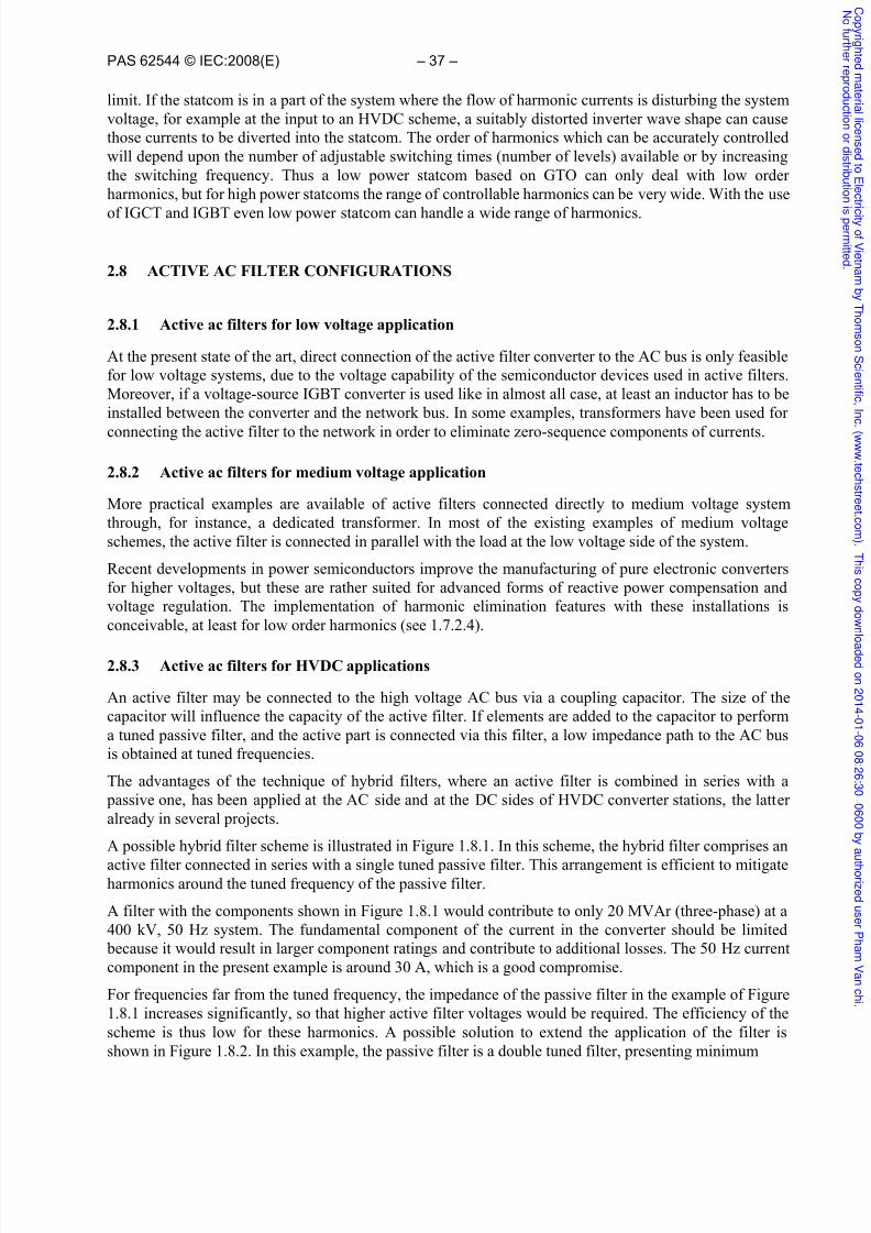
7/25/2019 iecpas62544ed1.0en.pdf
http://slidepdf.com/reader/full/iecpas62544ed10enpdf 39/58
PAS 62544 © IEC:2008(E) – 37 –
limit. If the statcom is in a part of the system where the flow of harmonic currents is disturbing the systemvoltage, for example at the input to an HVDC scheme, a suitably distorted inverter wave shape can causethose currents to be diverted into the statcom. The order of harmonics which can be accurately controlledwill depend upon the number of adjustable switching times (number of levels) available or by increasingthe switching frequency. Thus a low power statcom based on GTO can only deal with low orderharmonics, but for high power statcoms the range of controllable harmonics can be very wide. With the use
of IGCT and IGBT even low power statcom can handle a wide range of harmonics.
2.8 ACTIVE AC FILTER CONFIGURATIONS
2.8.1 Active ac filters for low voltage application
At the present state of the art, direct connection of the active filter converter to the AC bus is only feasiblefor low voltage systems, due to the voltage capability of the semiconductor devices used in active filters.Moreover, if a voltage-source IGBT converter is used like in almost all case, at least an inductor has to beinstalled between the converter and the network bus. In some examples, transformers have been used for
connecting the active filter to the network in order to eliminate zero-sequence components of currents.
2.8.2 Active ac filters for medium voltage application
More practical examples are available of active filters connected directly to medium voltage systemthrough, for instance, a dedicated transformer. In most of the existing examples of medium voltageschemes, the active filter is connected in parallel with the load at the low voltage side of the system.
Recent developments in power semiconductors improve the manufacturing of pure electronic convertersfor higher voltages, but these are rather suited for advanced forms of reactive power compensation andvoltage regulation. The implementation of harmonic elimination features with these installations isconceivable, at least for low order harmonics (see 1.7.2.4).
2.8.3 Active ac filters for HVDC applications
An active filter may be connected to the high voltage AC bus via a coupling capacitor. The size of thecapacitor will influence the capacity of the active filter. If elements are added to the capacitor to performa tuned passive filter, and the active part is connected via this filter, a low impedance path to the AC busis obtained at tuned frequencies.
The advantages of the technique of hybrid filters, where an active filter is combined in series with a passive one, has been applied at the AC side and at the DC sides of HVDC converter stations, the latteralready in several projects.
A possible hybrid filter scheme is illustrated in Figure 1.8.1. In this scheme, the hybrid filter comprises an
active filter connected in series with a single tuned passive filter. This arrangement is efficient to mitigateharmonics around the tuned frequency of the passive filter.
A filter with the components shown in Figure 1.8.1 would contribute to only 20 MVAr (three-phase) at a400 kV, 50 Hz system. The fundamental component of the current in the converter should be limited because it would result in larger component ratings and contribute to additional losses. The 50 Hz currentcomponent in the present example is around 30 A, which is a good compromise.
For frequencies far from the tuned frequency, the impedance of the passive filter in the example of Figure1.8.1 increases significantly, so that higher active filter voltages would be required. The efficiency of thescheme is thus low for these harmonics. A possible solution to extend the application of the filter isshown in Figure 1.8.2. In this example, the passive filter is a double tuned filter, presenting minimum
C o p y r i gh
t e d m
a t er i al l i c
en
s e d t oE l e
c t r i c i t y of V i e
t n am b
y T h
om
s on
S c i en
t i f i c ,I n
c
. ( www. t e
c h
s t r e e t . c om
) .T h i s
c o p y d ownl o
a d e d on2
0 1 4 - 0 1 - 0
6 0 8 : 2
6 : 3
0 - 0
6 0 0 b y a u t h or i z
e d u s er P h
am V
an
c h i .
N of ur t h
er r e
pr o
d u c t i on
or
d i s
t r i b u t i oni
s p er mi t t e
d .

7/25/2019 iecpas62544ed1.0en.pdf
http://slidepdf.com/reader/full/iecpas62544ed10enpdf 40/58
– 38 – PAS 62544 © IEC:2008(E)
impedance at the 19th and 37th harmonics. In thiscase, the active filter can mitigate a wide rangeof harmonics. The reactive power and thefundamental frequency current in the filter arenearly the same as in the previous case.Therefore, this scheme offers a better cost- benefit ratio compared to the previous one.
In some HVDC applications, larger reactive power may be desirable at the active filter branch. Or an active filter may be installed inseries with an existing passive filter, to improvea scheme already in operation. In both cases, thefundamental current in the filter will beconsiderable, which should be disadvantageouscompared with the previous examples, as thefundamental current flows through the active part of the filter as well. Figure 1.8.3 shows asolution that can be used in this case to prevent
the fundamental current from flowing in theactive filter. In this figure, an LC circuit tuned atthe fundamental frequency was introduced in parallel with the active part. The LC path takesover the fundamental component of the current,while the harmonics flow in the active part. Thissolution is used in the active AC filter installedat the Tjele station (Eltra), in Denmark.
During network disturbances or filter switching,high transient currents will flow in the activefilter. To cope with this, the active filter should
be equipped with a fast by-passing device, like athyristor switch. The by-pass should be initiatedif overcurrent is detected and be removed afterthe overcurrent has disappeared, with a delay ofsome hundred milliseconds to match the networktypical disturbance times.
Figure 1.8.1: Active filter connected to the HV systemthrough a single-tuned passive filter
Figure 1.8.2: Active filter connected to the HV systemthrough a double-tuned passive filter
2.9 SERIES CONNECTED ACTIVE
FILTERS
This solution is feasible if the current in theinsertion point is low. However, in most cases, atleast several hundred amperes flow in the line,which makes this arrangement costly withrespect to installation and losses. In addition theequipment must be located at line potential,which increases the cost as well. Due to thesereasons, this solution is not recommended fortransmission systems, however it could befeasible for applications close to end-users in thedistribution systems to improve voltage quality.
Figure 1.8.3: Using an LC circuit to deviate the fundamental current
component
C o p y r i gh
t e d m
a t er i al l i c
en
s e d t oE l e
c t r i c i t y of V i e
t n am b
y T h
om
s on
S c i en
t i f i c ,I n
c
. ( www. t e
c h
s t r e e t . c om
) .T h i s
c o p y d ownl o
a d e d on2
0 1 4 - 0 1 - 0
6 0 8 : 2
6 : 3
0 - 0
6 0 0 b y a u t h or i z
e d u s er P h
am V
an
c h i .
N of ur t h
er r e
pr o
d u c t i on
or
d i s
t r i b u t i oni
s p er mi t t e
d .

7/25/2019 iecpas62544ed1.0en.pdf
http://slidepdf.com/reader/full/iecpas62544ed10enpdf 41/58
PAS 62544 © IEC:2008(E) – 39 –
2.10 CONTROL SYSTEM
2.10.1 Introduction
Various control algorithms exist that are applied to active power filtering. It is not the aim of this
document to discuss the various advantages and disadvantages of each but rather to provide a holistic ideaof the most well-known techniques. Some of these algorithms were evaluated in reference [27].
Some of the most common algorithms that can be used are described below.
2.10.2 Description of a Generic Active Power Filter Controller
A non-linear load generates fundamental frequency and harmonic currents il, as described in the preceding paragraphs. A per phase representation of an active power filter is shown in Figure 1.10.1. Theactive power filter injects a filter current if at the point of common coupling to compensate the non-linearload-current il..
The controller normally has as input the supply voltage us, and the line current il. The active filtercontroller consists normally of a digital outer-loop and analogue or digital inner loop (PWM) controller,imbedded into digital signal processors and gate arrays. The input to the PWM inner loop controller is theinjected current if and the DC-link voltage udc. Based on the generated reference current iref , the convertergenerates a current. This current is filtered with a low-pass filter with at least 1 kHz – 2 kHz cut-offfrequency. Normally a step-up transformer is provided. In order to have a bandwidth of for instance1 kHz – 2 kHz, the required switching frequency of the active filter should be at least 3 kHz – 5 kHz.
Converter
Figure 1.10.1: Per-phase Schematic Diagram of Active Filter and Controller
The injected current if , of an idealised active filter is such that the instantaneous sum of this injectedcurrent and the distorted load current is equal to the active current ia,. In practice the active current is anideal sinusoid with the amplitude proportional to the load conductance G at fundamental frequency, as
C o p y r i gh
t e d m
a t er i al l i c
en
s e d t oE l e
c t r i c i t y of V i e
t n am b
y T h
om
s on
S c i en
t i f i c ,I n
c
. ( www. t e
c h
s t r e e t . c om
) .T h i s
c o p y d ownl o
a d e d on2
0 1 4 - 0 1 - 0
6 0 8 : 2
6 : 3
0 - 0
6 0 0 b y a u t h or i z
e d u s er P h
am V
an
c h i .
N of ur t h
er r e
pr o
d u c t i on
or
d i s
t r i b u t i oni
s p er mi t t e
d .

7/25/2019 iecpas62544ed1.0en.pdf
http://slidepdf.com/reader/full/iecpas62544ed10enpdf 42/58
– 40 – PAS 62544 © IEC:2008(E)
discussed in the following equation (assuming us as the fundamental frequency component of the supplyvoltage) [28],[29]:
External inputs to the active filter controller may also be included to input the set references formaximum harmonic levels, THD, individual harmonic limits, reactive power demands, etc.
2.10.3 Calculation of Reference Current
As indicated in Figure 1.10.1, the reference current iref is an instantaneous current to be generated fromthe measured supply voltage us(t), the load current il(t) and external inputs. Different control algorithmsmay be used to generate this reference current iref . These algorithms are generated from time-domain andfrequency domain approaches. Instantaneous Reactive Power Theory (IRPT)
Fryze [29] is accredited as being the first to calculate fictitious power in the time domain in 1932. He sub-
divided the apparent power into two orthogonal components namely active power and fictitious power.Active power is based on the rate of energy transferred per time unit and is only available after sometime. This means that it is not possible to compensate for fictitious power components in real-time. Thisapproach is recommended by the International Electrotechnical Commission (IEC). Several time-domainimplementations of active filter control have been used in the past [28],[30],[31],[32],[33],[34], [35], [36].
One of the most successfully commercialised algorithms for active filter controllers is based on theInstantaneous Reactive Power Theory (IRPT). Akagi [31] introduced the IRPT, depicted in Figure 2.2. Hedefined a new electrical quantity, the instantaneous reactive power (q) as a unique value determined byusing the instantaneous values of the three-phase voltages and load currents. The related equations arealso
Figure 2.2: Block Diagram of IRPT.
(4)
C o p y r i gh
t e d m
a t er i al l i c
en
s e d t oE l e
c t r i c i t y of V i e
t n am b
y T h
om
s on
S c i en
t i f i c ,I n
c
. ( www. t e
c h
s t r e e t . c om
) .T h i s
c o p y d ownl o
a d e d on2
0 1 4 - 0 1 - 0
6 0 8 : 2
6 : 3
0 - 0
6 0 0 b y a u t h or i z
e d u s er P h
am V
an
c h i .
N of ur t h
er r e
pr o
d u c t i on
or
d i s
t r i b u t i oni
s p er mi t t e
d .

7/25/2019 iecpas62544ed1.0en.pdf
http://slidepdf.com/reader/full/iecpas62544ed10enpdf 43/58
PAS 62544 © IEC:2008(E) – 41 –
(5)
(6)
(7)
(8)
The measured three-phase voltages and currents are converted into a-(3 co-ordinates using (5) and (6).The instantaneous power is defined as the vector sum of the dot products of the a-(3 co-ordinates andreactive power as the vector product of the a-(3 co-ordinates as shown in (7). The fundamental of thesource current is transformed by these calculations to DC components of the instantaneous active andreactive power and harmonic values. A high-pass filter and the conversion back to three phases with (8)
can extract the harmonic components. The theory is also extended to include zero-phase sequencecomponents and instantaneous active power (p). It was implemented in various three-phase topologies[30],[31].
2.10.4 Synchronous Reference Frame (SRF)
Divan [32] implemented the Synchronous Reference Frame (SRF) technique to be used as a controlalgorithm in a compensator as shown in Figure 1.10.3.
The corresponding equations are:(9)
C o p y r i gh
t e d m
a t er i al l i c
en
s e d t oE l e
c t r i c i t y of V i e
t n am b
y T h
om
s on
S c i en
t i f i c ,I n
c
. ( www. t e
c h
s t r e e t . c om
) .T h i s
c o p y d ownl o
a d e d on2
0 1 4 - 0 1 - 0
6 0 8 : 2
6 : 3
0 - 0
6 0 0 b y a u t h or i z
e d u s er P h
am V
an
c h i .
N of ur t h
er r e
pr o
d u c t i on
or
d i s
t r i b u t i oni
s p er mi t t e
d .

7/25/2019 iecpas62544ed1.0en.pdf
http://slidepdf.com/reader/full/iecpas62544ed10enpdf 44/58
– 42 – PAS 62544 © IEC:2008(E)
(10)
(11)
The three-phase currents are converted into the two-phase a-(3 co-ordinates in a similar way as inequation (6), excluding the zero-phase sequence components. By using (9), these two stationary referenceframe quantities (is) are then converted into two synchronous rotating reference frame quantities (ie). Thefundamental frequency components are now transformed into a DC quantity and the harmonics to ACcomponents which are separated using a low pass filter . A PI controller ensures zero steady state controlerror. The resulting DC components are then converted back to the stationary reference frame with (10).The three active current components of the load current are calculated by using (11).
2.10.5 Other Control Approaches
Bhattacharya [36] introduced a method to control an active filter based on the synchronous reference
frame technique [32] extended into the flux domain by integrating the voltage. Several other approachesare developed which differs somewhat from these original approaches. Some implementations estimatorsused Neural Networks and Kalman filters in electrical networks with highly dynamic characteristics, withvaried success [34]. In some cases the harmonic current reference is provided in an open-loop or feed-forward way and injected without any line current feed-back.
Figure 1.10.3 :Block Diagram of SRF.
C o p y r i gh
t e d m
a t er i al l i c
en
s e d t oE l e
c t r i c i t y of V i e
t n am b
y T h
om
s on
S c i en
t i f i c ,I n
c
. ( www. t e
c h
s t r e e t . c om
) .T h i s
c o p y d ownl o
a d e d on2
0 1 4 - 0 1 - 0
6 0 8 : 2
6 : 3
0 - 0
6 0 0 b y a u t h or i z
e d u s er P h
am V
an
c h i .
N of ur t h
er r e
pr o
d u c t i on
or
d i s
t r i b u t i oni
s p er mi t t e
d .
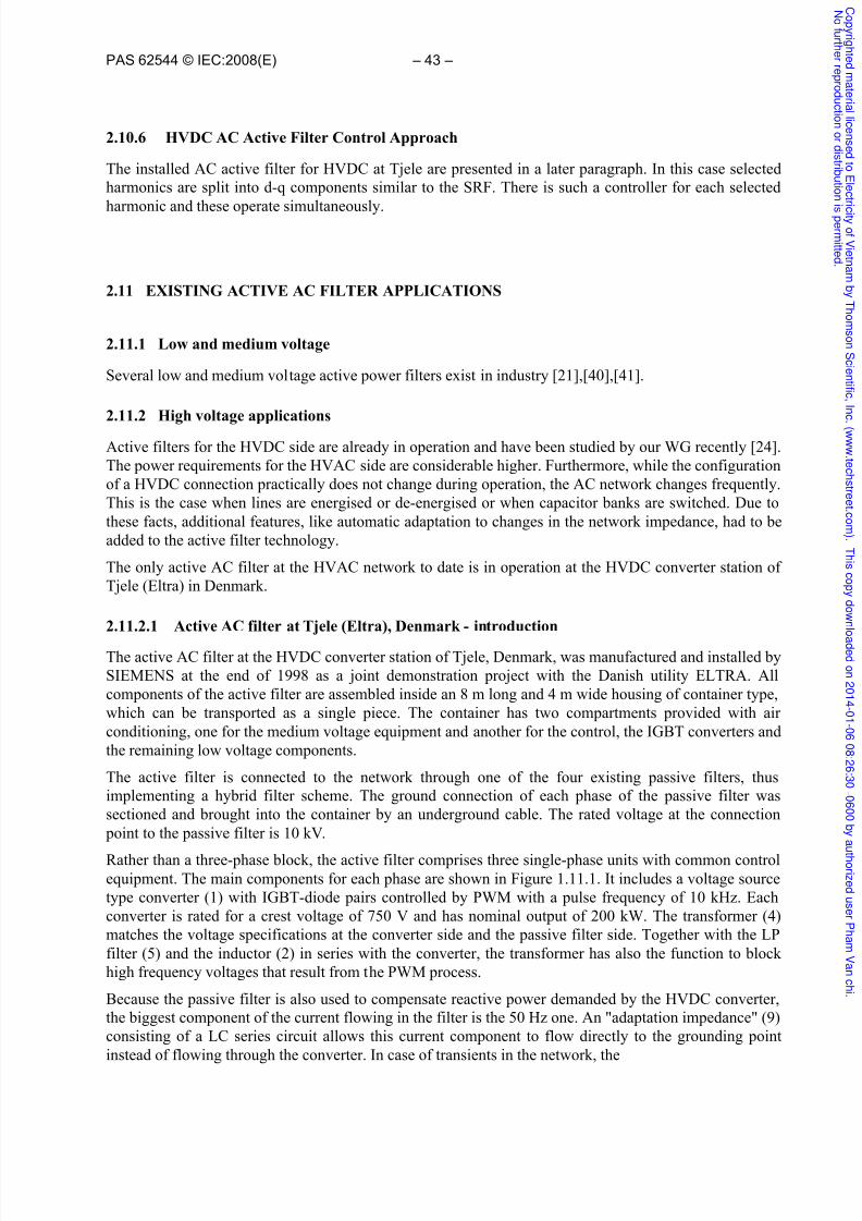
7/25/2019 iecpas62544ed1.0en.pdf
http://slidepdf.com/reader/full/iecpas62544ed10enpdf 45/58
PAS 62544 © IEC:2008(E) – 43 –
2.10.6 HVDC AC Active Filter Control Approach
The installed AC active filter for HVDC at Tjele are presented in a later paragraph. In this case selectedharmonics are split into d-q components similar to the SRF. There is such a controller for each selected
harmonic and these operate simultaneously.
2.11 EXISTING ACTIVE AC FILTER APPLICATIONS
2.11.1 Low and medium voltage
Several low and medium voltage active power filters exist in industry [21],[40],[41].
2.11.2 High voltage applications
Active filters for the HVDC side are already in operation and have been studied by our WG recently [24].The power requirements for the HVAC side are considerable higher. Furthermore, while the configurationof a HVDC connection practically does not change during operation, the AC network changes frequently.This is the case when lines are energised or de-energised or when capacitor banks are switched. Due tothese facts, additional features, like automatic adaptation to changes in the network impedance, had to beadded to the active filter technology.
The only active AC filter at the HVAC network to date is in operation at the HVDC converter station ofTjele (Eltra) in Denmark.
2.11.2.1 Active AC filter at Tjele (Eltra), Denmark - introduction
The active AC filter at the HVDC converter station of Tjele, Denmark, was manufactured and installed bySIEMENS at the end of 1998 as a joint demonstration project with the Danish utility ELTRA. Allcomponents of the active filter are assembled inside an 8 m long and 4 m wide housing of container type,which can be transported as a single piece. The container has two compartments provided with airconditioning, one for the medium voltage equipment and another for the control, the IGBT converters andthe remaining low voltage components.
The active filter is connected to the network through one of the four existing passive filters, thusimplementing a hybrid filter scheme. The ground connection of each phase of the passive filter wassectioned and brought into the container by an underground cable. The rated voltage at the connection point to the passive filter is 10 kV.
Rather than a three-phase block, the active filter comprises three single-phase units with common controlequipment. The main components for each phase are shown in Figure 1.11.1. It includes a voltage sourcetype converter (1) with IGBT-diode pairs controlled by PWM with a pulse frequency of 10 kHz. Eachconverter is rated for a crest voltage of 750 V and has nominal output of 200 kW. The transformer (4)matches the voltage specifications at the converter side and the passive filter side. Together with the LPfilter (5) and the inductor (2) in series with the converter, the transformer has also the function to blockhigh frequency voltages that result from the PWM process.
Because the passive filter is also used to compensate reactive power demanded by the HVDC converter,the biggest component of the current flowing in the filter is the 50 Hz one. An "adaptation impedance" (9)consisting of a LC series circuit allows this current component to flow directly to the grounding pointinstead of flowing through the converter. In case of transients in the network, the
C o p y r i gh
t e d m
a t er i al l i c
en
s e d t oE l e
c t r i c i t y of V i e
t n am b
y T h
om
s on
S c i en
t i f i c ,I n
c
. ( www. t e
c h
s t r e e t . c om
) .T h i s
c o p y d ownl o
a d e d on2
0 1 4 - 0 1 - 0
6 0 8 : 2
6 : 3
0 - 0
6 0 0 b y a u t h or i z
e d u s er P h
am V
an
c h i .
N of ur t h
er r e
pr o
d u c t i on
or
d i s
t r i b u t i oni
s p er mi t t e
d .

7/25/2019 iecpas62544ed1.0en.pdf
http://slidepdf.com/reader/full/iecpas62544ed10enpdf 46/58
– 44 – PAS 62544 © IEC:2008(E)
Figure 1.11.1: Structure of the active AC filter at the HVDC station of Tjele (ELTRA), Denmark
C o p y r i gh
t e d m
a t er i al l i c
en
s e d t oE l e
c t r i c i t y of V i e
t n am b
y T h
om
s on
S c i en
t i f i c ,I n
c
. ( www. t e
c h
s t r e e t . c om
) .T h i s
c o p y d ownl o
a d e d on2
0 1 4 - 0 1 - 0
6 0 8 : 2
6 : 3
0 - 0
6 0 0 b y a u t h or i z
e d u s er P h
am V
an
c h i .
N of ur t h
er r e
pr o
d u c t i on
or
d i s
t r i b u t i oni
s p er mi t t e
d .

7/25/2019 iecpas62544ed1.0en.pdf
http://slidepdf.com/reader/full/iecpas62544ed10enpdf 47/58
PAS 62544 © IEC:2008(E) – 45 –
thyristor switch (3) provides fast short-circuiting of the transformer LV winding, limiting the current inthe converter during the time of the disturbance. The vacuum switch (6) and a set of switches (8) perform by-pass and isolation of the active filter, if required.
The function of the active filter is the elimination or reduction of several harmonics simultaneously at the400 kV bus voltage. The following operation modes are possible:
• simultaneous elimination of the 23rd
, 25th
, 35th
, 37th
, 47th
and 49th
harmonics • mitigation of the 5th harmonic (mainly coming from the network)
• simultaneous reduction of the 5th harmonics and one or more harmonics of the 1st case.
2.11.2.2 Harmonic control system
The principle of the harmonic control is illustrated in Figure 1.11.2. The voltage at the 400 kV bus issensed by a voltage transformer and transmitted to the active filter through optical fibres ending directlyin the control equipment. Each selected harmonic present in the input signal is split into two componentsin the frequency domain and separated by the block (3). This one feeds a complex controller (4), whichhas essentially a PI characteristic. The output of the controller is than shifted back to the time domain by
multiplication by cos(hωt) and sin(hωt), where h is the order of the harmonic, ωis the network angularfrequency and t is the time. There is such a controller for each selected harmonic and these operatesimultaneously.
The PWM amplifier block (8) embodies the IGBT converter and other above listed components of theactive filter. The output voltage Uactive of the active filter influences the filter current I flt, which iscombined with the harmonic current Iharm in the network (essentially due to the HVDC converter), in
Figure 1.11.2: Basic harmonic control loop of the active AC filter at Tjele, Denmark
C o p y r i gh
t e d m
a t er i al l i c
en
s e d t oE l e
c t r i c i t y of V i e
t n am b
y T h
om
s on
S c i en
t i f i c ,I n
c
. ( www. t e
c h
s t r e e t . c om
) .T h i s
c o p y d ownl o
a d e d on2
0 1 4 - 0 1 - 0
6 0 8 : 2
6 : 3
0 - 0
6 0 0 b y a u t h or i z
e d u s er P h
am V
an
c h i .
N of ur t h
er r e
pr o
d u c t i on
or
d i s
t r i b u t i oni
s p er mi t t e
d .

7/25/2019 iecpas62544ed1.0en.pdf
http://slidepdf.com/reader/full/iecpas62544ed10enpdf 48/58
– 46 – PAS 62544 © IEC:2008(E)
order to eliminate the harmonics in the 400 kV voltage bus, U bus. Because the harmonic impedance at theAC bus changes with the network configuration, a self-tuning system (7) follows up these changes andadapts the harmonic controllers accordingly.
2.11.2.3 Field measurements
The graphics in Figure 1.11.3 shows results of sitemeasurements.
The figure shows plots from a measurements of the400 kV busbar voltage at the of the Eltra's Tjelesubstation, Denmark without (top) and with (bottom)active filter control. It can be seen that the activefilter causes a strong reduction of the selectedharmonics. A reduction of more than 30 dBV isshown (Figure 1.11.3) for the 23rd harmonic in thiscase.
The measurement was performed using a frequency
analyser connected to the input of the active filtercontrol equipment through D/A converter (opticalinput, block 2 on the block diagram in Figure1.11.2).
Measurements were also performed for the current inthe parallel filters of the station. These measurementsshow that when the active filter is in operation,eliminating the voltage on the 400 kV bus for theselected harmonics, no current of these harmonicsflows in the parallel filters. This result is interesting, because it means that no other filters are required at
the station for the harmonics controlled by the activefilter.
Figure 1.11.3: Plots from site measurements.Top, without; bottom, with active filter control.
2.12 OVERVIEW ON FILTER SOLUTIONS FOR HVDC SYSTEMS
This section gives an overview on the application of the previously discussed filter technologies in HVDCstations. A comparison using study cases based on the Cigré benchmark model is also included.
2.12.1 Solution with conventional passive filters
In the Cigré technical brochure No 139 [25], passive AC filters for HVDC systems are described anddiscussed in detail. For a typical HVDC converter station, a reactive power installation of 50% - 60% ofthe active power rating is required in order to obtain reactive power balance with the AC system. Thereactive power installation will be divided into shunt capacitor banks, and a part of these banks will bedesigned as filters. In this way the demands of fundamental frequency reactive power and harmonicdistortion will be achieved. The AC filters, including their switchyard equipment can occupy over half thetotal land required by a typical converter station. Where the land is expensive, this could lead to a
C o p y r i gh
t e d m
a t er i al l i c
en
s e d t oE l e
c t r i c i t y of V i e
t n am b
y T h
om
s on
S c i en
t i f i c ,I n
c
. ( www. t e
c h
s t r e e t . c om
) .T h i s
c o p y d ownl o
a d e d on2
0 1 4 - 0 1 - 0
6 0 8 : 2
6 : 3
0 - 0
6 0 0 b y a u t h or i z
e d u s er P h
am V
an
c h i .
N of ur t h
er r e
pr o
d u c t i on
or
d i s
t r i b u t i oni
s p er mi t t e
d .
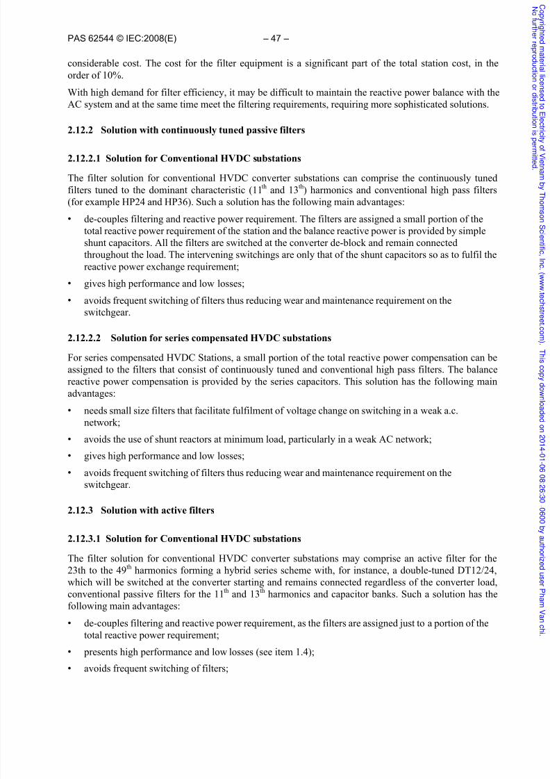
7/25/2019 iecpas62544ed1.0en.pdf
http://slidepdf.com/reader/full/iecpas62544ed10enpdf 49/58
PAS 62544 © IEC:2008(E) – 47 –
considerable cost. The cost for the filter equipment is a significant part of the total station cost, in theorder of 10%.
With high demand for filter efficiency, it may be difficult to maintain the reactive power balance with theAC system and at the same time meet the filtering requirements, requiring more sophisticated solutions.
2.12.2 Solution with continuously tuned passive filters
2.12.2.1 Solution for Conventional HVDC substations
The filter solution for conventional HVDC converter substations can comprise the continuously tunedfilters tuned to the dominant characteristic (11th and 13th) harmonics and conventional high pass filters(for example HP24 and HP36). Such a solution has the following main advantages:
• de-couples filtering and reactive power requirement. The filters are assigned a small portion of thetotal reactive power requirement of the station and the balance reactive power is provided by simpleshunt capacitors. All the filters are switched at the converter de-block and remain connectedthroughout the load. The intervening switchings are only that of the shunt capacitors so as to fulfil thereactive power exchange requirement;
• gives high performance and low losses;
• avoids frequent switching of filters thus reducing wear and maintenance requirement on theswitchgear.
2.12.2.2 Solution for series compensated HVDC substations
For series compensated HVDC Stations, a small portion of the total reactive power compensation can beassigned to the filters that consist of continuously tuned and conventional high pass filters. The balancereactive power compensation is provided by the series capacitors. This solution has the following mainadvantages:
• needs small size filters that facilitate fulfilment of voltage change on switching in a weak a.c.network;
• avoids the use of shunt reactors at minimum load, particularly in a weak AC network;
• gives high performance and low losses;
• avoids frequent switching of filters thus reducing wear and maintenance requirement on theswitchgear.
2.12.3 Solution with active filters
2.12.3.1 Solution for Conventional HVDC substations
The filter solution for conventional HVDC converter substations may comprise an active filter for the23th to the 49th harmonics forming a hybrid series scheme with, for instance, a double-tuned DT12/24,which will be switched at the converter starting and remains connected regardless of the converter load,conventional passive filters for the 11th and 13th harmonics and capacitor banks. Such a solution has thefollowing main advantages:
• de-couples filtering and reactive power requirement, as the filters are assigned just to a portion of thetotal reactive power requirement;
• presents high performance and low losses (see item 1.4);
• avoids frequent switching of filters;
C o p y r i gh
t e d m
a t er i al l i c
en
s e d t oE l e
c t r i c i t y of V i e
t n am b
y T h
om
s on
S c i en
t i f i c ,I n
c
. ( www. t e
c h
s t r e e t . c om
) .T h i s
c o p y d ownl o
a d e d on2
0 1 4 - 0 1 - 0
6 0 8 : 2
6 : 3
0 - 0
6 0 0 b y a u t h or i z
e d u s er P h
am V
an
c h i .
N of ur t h
er r e
pr o
d u c t i on
or
d i s
t r i b u t i oni
s p er mi t t e
d .

7/25/2019 iecpas62544ed1.0en.pdf
http://slidepdf.com/reader/full/iecpas62544ed10enpdf 50/58
– 48 – PAS 62544 © IEC:2008(E)
• coverage of non-characteristic harmonics without additional filter hardware.
2.12.3.2 Solution for series compensated HVDC substations
For series compensated HVDC Stations, a small portion of the total reactive power compensation can beassigned to the filters that consist of active (hybrid) filters. The balance reactive power compensation is
provided by the series capacitors. This solution has the following main advantages: • needs small size filters that facilitate fulfilment of voltage change on switching in a weak a.c.
network;
• avoids the use of shunt reactors or Static Var Compensators (SVC) at minimum load, particularly in aweak a.c. network;
• gives high performance (see item 1.4) and low losses;
• avoids frequent switching of filters thus reducing wear and maintenance requirement on theswitchgear.
2.12.4 Solution with continuously tuned passive filters and active filters
This solution may comprise active ac filters with moderate amplifier rating and continuously tuned passive filters, providing high efficiency with both series compensated and conventional HVDC converterstations. In this solution continuously tuned 11 th and 13th filters can be combined with an active filter forhigher harmonics (for example, 23rd to 49th).
2.12.5 Study cases with the Cigré HVDC model
This section presents results obtained using three AC filter solutions for the Cigré HVDC model. Themodel is a 1 000 MW, 500 kV monopolar HVDC transmission system with a DC cable.
A system frequency range of 50 Hz ± 0.5 Hz was considered.
The three filter configurations that satisfy the specified performance are
1 - conventional 11/13th, 24/36th and high pass third harmonic tuned filters (HP3 filters);
2 - continuously tuned 11th and 13th filters, with conventional HP24, HP36 and HP3 passive filters;
3 - continuously tuned 11th and 13th filters, a conventional HP3 passive filter for the 3rd harmonic and
an active (hybrid) filter for higher order harmonics supplying 75 MVAR reactive power.
The used filter and system impedance data are presented in Figure 1.12.1 . The
performance requirements are defined in terms of the following parameters:
Table 1.12.1: Performance Requirements
Parameter Limit
Dn, (Individual Harmonic Distortion) 1.0 % for all odd harmonics
0.5 % for all even harmonics
THD 1.5 %
THFF 1.0 %
C o p y r i gh
t e d m
a t er i al l i c
en
s e d t oE l e
c t r i c i t y of V i e
t n am b
y T h
om
s on
S c i en
t i f i c ,I n
c
. ( www. t e
c h
s t r e e t . c om
) .T h i s
c o p y d ownl o
a d e d on2
0 1 4 - 0 1 - 0
6 0 8 : 2
6 : 3
0 - 0
6 0 0 b y a u t h or i z
e d u s er P h
am V
an
c h i .
N of ur t h
er r e
pr o
d u c t i on
or
d i s
t r i b u t i oni
s p er mi t t e
d .

7/25/2019 iecpas62544ed1.0en.pdf
http://slidepdf.com/reader/full/iecpas62544ed10enpdf 51/58
PAS 62544 © IEC:2008(E) – 49 –
AC Filter data at station A (375 kV): Filter Type→ 11th 13th HP3 3-phase Mvar at nominal ac voltage 43.8 31.2 60 C1, µF 1.16 0.84 1.61 L1, mH 72.17 72.17 789.31 C2, µF - - 12.84 L2, mH - - - R1, Ω - - 1800 R2, Ω - - -
AC Filter data at station B (230 kV) Filter Type→ 11th 13th HP3 3-phase Mvar at nominal ac voltage 43.8 31.2 60 C1, µF 2.61 1.87 3.61 L1, mH 32.07 32.07 350.8 C2, µF - - 28.88 L2, mH - - - R1, Ω - - 850 R2, Ω - - -
HP36 11/13th 37.5 90 1.00 2.39 7.80 29.65
- 85.44 - 0.83
350 - - 65
HP36 11/13th 37.5 90 2.26 5.378 3.47 13.18
- 192.25 - 0.37
170 - - 30
Figure 1.12.1: Filter and system data
C o p y r i gh
t e d m
a t er i al l i c
en
s e d t oE l e
c t r i c i t y of V i e
t n am b
y T h
om
s on
S c i en
t i f i c ,I n
c
. ( www. t e
c h
s t r e e t . c om
) .T h i s
c o p y d ownl o
a d e d on2
0 1 4 - 0 1 - 0
6 0 8 : 2
6 : 3
0 - 0
6 0 0 b y a u t h or i z
e d u s er P h
am V
an
c h i .
N of ur t h
er r e
pr o
d u c t i on
or
d i s
t r i b u t i oni
s p er mi t t e
d .

7/25/2019 iecpas62544ed1.0en.pdf
http://slidepdf.com/reader/full/iecpas62544ed10enpdf 52/58
– 50 – PAS 62544 © IEC:2008(E)
The highest values of each of the performance parameters at rated (1 000 MW) power are:
Table 1.12.2: Performance Results of Filter
Performance parameter value Filter
configuration Dn/n (%) THD (%) THFF (%) 1 0.90/5 1.41 0.97
2 0.91/5 1.34 0.83
3 0.91/5 1.28 0.64
The configurations with the continuously tuned filter and active filters (configuration 3) give better performance as compared to that with the conventional passive filters.
These results cannot be generalised. For drawing conclusions for specific projects, the calculations need
to consider realistic input data regarding the AC system, e.g. harmonic impedance and reactivecompensation requirements. Also filter detuning (important for passive filters) has to be considered.
2.13 FUTURE TECHNOLOGIES
Voltage Source Converters (VSC) are expected for DC interconnections in the future. By this reason lessrequirements for external reactive power demand and low frequency harmonic distortion compensationwould be required in the future. In such a case at large power ratings, passive or small active filters may be included to compensate non-characteristics harmonics at higher frequencies than the PWM switchingfrequency of the main VSC. By this method of operation, the VSC can compensate lower order
harmonics internally. At this moment voltage source DC-link converters are available at the 100 MVA –350 MVA power range at DC-links of 100 kV – 150 kV DC.
The application on the LV and MV range in Custom power, active power and power quality mitigatingdevices are expected to accelerate in the future, increasing both in power rating and performance.
2.14 CONCLUSIONS ON ACTIVE AC FILTERS
• For HVDC solutions a hybrid active power filter would be required in order to minimize the powerrating of the active power filter and maximize the performance of the full filter.
• For retrofitting existing HVDC links with increased power quality problems in networks, it is
expected that active filter configurations will be added to existing passive filter solutions.
• For series compensated converter HVDC systems, hybrid active power filters or tuneable passivesolutions may be more cost effective than a pure passive solution.
• Active filters using multi-level topologies may be connected directly to the MV and LV networkswithout the use of transformers.
• It may be advantageous to connect active filters for HV networks via an existing or special couplingtransformer. In such a case the current regulating reactor may be included into the design of the seriesimpedance of the transformer. For protection purposes it is unlikely to connect the active filter on HVnetworks directly onto the supply voltage.
• In the future, voltage source converter DC links may combine the harmonic filter and reactive powerdemand into a single power solution for HV networks.
C o p y r i gh
t e d m
a t er i al l i c
en
s e d t oE l e
c t r i c i t y of V i e
t n am b
y T h
om
s on
S c i en
t i f i c ,I n
c
. ( www. t e
c h
s t r e e t . c om
) .T h i s
c o p y d ownl o
a d e d on2
0 1 4 - 0 1 - 0
6 0 8 : 2
6 : 3
0 - 0
6 0 0 b y a u t h or i z
e d u s er P h
am V
an
c h i .
N of ur t h
er r e
pr o
d u c t i on
or
d i s
t r i b u t i oni
s p er mi t t e
d .

7/25/2019 iecpas62544ed1.0en.pdf
http://slidepdf.com/reader/full/iecpas62544ed10enpdf 53/58
PAS 62544 © IEC:2008(E) – 51 –
3 BIBLIOGRAPHY
[I] CIGRÉ WG 14-30. “Guide to the Specification and Design Evaluation of AC Filters for HVDCSystems.”, Technical Brochure 139, April 1999.
[2] CIGRÉ Task Force 14.03.02, "DC Side Harmonics and Filtering in HVDC Transmission Systems."Technical Brochure Ref. 92 , April 1995.
[3] “Directives concerning the protection of telecommunication lines against harmful effects fromelectricity lines”, by The International Telecommunication Union, New Dehli-1960, edition 1963.
[4] Zhang W., “On feedback Control of Active DC Filters in HVDC Cable links with coastal lines”.Royal Institute of Technology, Stockholm 1995.
[5] Mohan N., Peterson H.A., Long W.F, Dreifuerst G.R., Vithayathil J.J., “Active filters for ac harmonicsuppression” ,A 77 026-8, IEEE 1977.
[6] Mohan N., “Modified high pass filters for HVDC converter terminals”, A 79 423-5, CH1458-
9/79/0000-4235, IEEE 1979. [7] Wong C., “Feasibility Study of AC- and DC-side Active Filters for HVDC Converter Terminals”,
IEEE Trans. on Power Delivery, vol 4, no. 4, pp. 2067-2075, Oct 1989.
[8] Broche C, “Harmonic reduction in dc link current of a PWM induction motor drive by activefiltering”, IEEE Trans. Power Electronics, vol. 7, no. 4, pp 633-643, Oct. 1992.
[9] Peng F.Z., “A new approach to harmonic compensation in power systems-series connection of passiveand active filters”, IEEE Trans. on industry Applications, Vol. 27, No.6, pp. 1020-1025, Nov./Dic.1991.
[10] Vaupel G., “Wide-band filter with actively reduced losses for power systems”, EPE ’95, Sevilla,Vol. 0. Pp. 1-16.
[II] Watanabe E.H., “Series active filter for the DC side of the HVDC transmission systems”, Proc.IPEC-Tokyo, Japan, pp 1024-1030, Apr. 1990.
[12] W. Stygar and G. Gerdin, “High Frequency Rogowski Coil Response Characteristics,” IEEE Trans.on Plasma Science, vol. PS-10, no. 1, March 1982, pp. 40-44.
[13] H.P. Mercure, P. Bard, “Direct measurement of residual harmonic currents on a + and - 450kV DCline using Rogowski coils,” 7th International Symposium on High Voltage Engineering, Dresden,August 1991.
[14] Nyman et al, “Baltic Cable,” Cigre Colloquium Paper 1.4, 1995.
[15] Nyman et al, “The Baltic Cable HVDC project” Cigre Session, 1996.
[16] Zhang et al, “Active DC filter for HVDC system- A Test Installation in the Konti-Skan dc Link atLindome Converter Station,” IEEE Trans. on Power Delivery, vol. 8, no. 3, July 1993, pp. 1599-1606.
[17] Holtzhausen, Enslin, Venter, “An evaluation of different active filter topologies for the Cahora BassaHVDC project,” Cigré SC-14 International Colloquium on HVDC and FACTS, Johannesburg,South Africa, 28 - 30 September 1997.
[18] A Horn; LA Pittorino; JHR Enslin: "Evaluation of Active Power Filter Algorithms under non-sinusoidal and unbalanced conditions," IEEE PES, 7 th International Conference on Harmonicsand Quality of Power (ICHQP-96), Las Vegas, Nevada, USA, pp 217-224, 16-18 Oct 1996
C o p y r i gh
t e d m
a t er i al l i c
en
s e d t oE l e
c t r i c i t y of V i e
t n am b
y T h
om
s on
S c i en
t i f i c ,I n
c
. ( www. t e
c h
s t r e e t . c om
) .T h i s
c o p y d ownl o
a d e d on2
0 1 4 - 0 1 - 0
6 0 8 : 2
6 : 3
0 - 0
6 0 0 b y a u t h or i z
e d u s er P h
am V
an
c h i .
N of ur t h
er r e
pr o
d u c t i on
or
d i s
t r i b u t i oni
s p er mi t t e
d .

7/25/2019 iecpas62544ed1.0en.pdf
http://slidepdf.com/reader/full/iecpas62544ed10enpdf 54/58
– 52 – PAS 62544 © IEC:2008(E)
[19] LA Pittorino; JA du Toit; JHR Enslin: "Evaluation of converter topologies and controllers for powerquality compensators under unbalanced conditions", IEEE Power Electronics SpecialistsConference (PESC-97), St Louis, Missouri, USA, pp 1127 - 1133, 22 - 27 June 1997.
[20] HN Holtzhausen, JHR Enslin, AC Britten, "The reduction in the equivalent disturbing current of anHVDC line using an active DC power filter", 8th International Power Quality Applications
Conference (PQA '98), Cape Town, SA, Session 5, 9-11 November 1998. [21] JHR Enslin, "Unified approach to power quality mitigation", IEEE International Symposium on
Industrial Electronics (ISIE'98), Vol 1, pp 8-11, 7-10 July 1998. (Invited plenary paper)
[22] T.N.Le, M.Pereira, K.Renz, G.Vaupel, "Active Damping of Resonances in Power Systems".IEEE/PES Summer Meeting, Vancouver, B.C., Canada, July 1993.
[23] M.Pereira, G.Wild, "Experience with the application of active AC and DC filter in HVDC systems",IEEE / PES T&D 2002 Latin America, São Paulo, Brazil, March 2002.
[24] Cigré Electra ref. no. 187, "Active DC filters in HVDC applications", WG 14.28, 1999.
[25] Cigré technical brochure no. 139, "Guide to the Specification and Design Evaluation of AC Filtersfor HVDC Systems", WG 14.30, 1999.
[26] Cigré technical brochure ref. no. 144, "Static synchronous compensator (STATCOM)", WG 14.19,1999.
[27] A Horn; LA Pittorino; JHR Enslin: "Evaluation of Active Power Filter Algorithms under non-sinusoidal and unbalanced conditions," IEEE PES, 7 th International Conference on Harmonics andQuality of Power (ICHQP-96), Las Vegas, Nevada, USA, pp 217-224, 16-18 Oct 1996.
[28] JHR Enslin; JD van Wyk: "A new control philosophy for power electronic converters as fictitious power compensators", IEEE Transactions on Power Electronics, vol PEL-5, no 1, pp 88-97, Jan1990.
[29] S. Fryze, “Wirk-, Blind-, und Scheinleistung in Elektrisch Stromkreisen mit nichtsinusoidalformigen
Verlauf von Strom und Spannung,” ETZ , vol. 53, no. 25, 1932, pp. 596-599, 625-627, 700-702. [30] H. Fujita and H. Akagi, “A Practical Approach to Harmonic Compensation in Power Systems -Series
Connection of Passive and Active Filters,” IEEE Trans. on Ind. Appl., vol. 27, no. 6, November/December 1991, pp.1020-1025.
[31] H. Akagi, Y. Kanazawa and A. Nabae, “Instantaneous Reactive Power Compensators ComprisingSwitching Devices without Energy Storage Components,” IEEE Trans. on Ind. Appl., vol. IA-20,no. 3, May/June 1984, pp. 625-630.
[32] S. Bhattacharya, D.M. Divan and B. Banerjee, “Synchronous Frame Harmonic Isolator using ActiveSeries Filter,” EPE 1991, pp. 3-030 - 3-035.
[33] P. Jintakosonwit, H. Fujita and H. Akagi: “Control and performance of a fully-digital-controlled
shunt active filter for installation on a power distribution system” IEEE Trans. on PowerElectronics, vol. 17, no. 1, Jan. 2002, pp. 132-140.
[34] JHR Enslin; JD van Wyk; M Naudé: "Adaptive closed-loop control of dynamic power filters asfictitious power compensators", IEEE Transactions on Industrial Electronics, vol IE-37, no 3, pp203-211, June 1990.
[35] G. Dinkel and R. Gretsch, “Kompensator für Oberschwingungen und Blindleistung,” ETZ Archiv,vol. 9 no. 1, pp. 9-14, 1987.
[36] S. Bhattacharya, A. Veltman, D.M. Divan and R.D. Lorenz, “Flux-Based Active Filter Controller,”IEEE Trans. on Ind. Appl., vol. 32, no. 3, May/June 1996, pp. 491-501.
C o p y r i gh
t e d m
a t er i al l i c
en
s e d t oE l e
c t r i c i t y of V i e
t n am b
y T h
om
s on
S c i en
t i f i c ,I n
c
. ( www. t e
c h
s t r e e t . c om
) .T h i s
c o p y d ownl o
a d e d on2
0 1 4 - 0 1 - 0
6 0 8 : 2
6 : 3
0 - 0
6 0 0 b y a u t h or i z
e d u s er P h
am V
an
c h i .
N of ur t h
er r e
pr o
d u c t i on
or
d i s
t r i b u t i oni
s p er mi t t e
d .

7/25/2019 iecpas62544ed1.0en.pdf
http://slidepdf.com/reader/full/iecpas62544ed10enpdf 55/58
PAS 62544 © IEC:2008(E) – 53 –
[37] M.Pereira, K.Sadek, "Application of Power Active Filters for Mitigation of Harmonics". StockholmPower Tech symposium, June 1995.
[38] D. Basic, V.S. Ramsden, and P.K. Muttik, “Harmonic Filtering of High-Power 12-Pulse RectifierLoads with a selective Hybrid Filter,” IEEE Trans. on Industrial Electronics, vol. 48, no. 6,December 2001, pp. 1118-1127.
[39] P-T Cheng, S. Bhattacharya and D.M. Divan, “Operations of the dominant harmonic active filter(DHAF) under realistic utility conditions”, IEEE Trans. on Industry Applications, vol 37, no 4, pp1037-1044, July/Aug 2001
[40] Akagi, H: “New Trends in Active Filters for Power Conditioning,” IEEE Trans. on IndustryApplications, vol. 32, no. 6, Nov./Dec. 1996, pp. 1312-1322.
[41] Cigré Working Group 14-31 - Technical report on custom power.
[42] J.H.R. Enslin and J.D. van Wyk, “Measurement and Compensation of Fictitious Power Under Nonsinusoidal Voltage and Current Conditions,” IEEE Trans. on Instrumentation and
Measurement , vol. 37, no. 3, September 1988, pp. 403-408.
[43] P.-J. Randewijk and J.H.R. Enslin, “Inverting DC Traction Substation with Active FilteringIncorporated,” IEEE PESC’95 Conf. Proceedings, Atlanta, USA, June 1995, pp.360-366.
[44] G.L. van Harmelen and J.H.R. Enslin, ”Real-Time Dynamic Control of Dynamic Power Filters inSupplies with High Contamination,” IEEE Trans. on Power Electr., vol. 8, no. 3, July 1993, pp.301-308.
[45] R.G. Coney, “The Impact of Power Quality on Industry in Africa,” IEEE AFRICON’96 Conf.Proceedings, Stellenbosch, South Africa, September 1996, pp. 21-27.
[46] A. van Zyl, J.H.R. Enslin and R. Spée, “A New Unified Approach to Power Quality Management,” IEEE Trans. on Industry Applications, vol 32, no 6, pp 1323-1330, Nov/Dec 1996.
[47] IEC 61000 (all parts), Electromagnetic compatibility (EMC)
[48] IEEE 519, IEEE Recommended Practices and Requirements for Harmonic Control in Electric Power Systems
____________
C o p y r i gh
t e d m
a t er i al l i c
en
s e d t oE l e
c t r i c i t y of V i e
t n am b
y T h
om
s on
S c i en
t i f i c ,I n
c
. ( www. t e
c h
s t r e e t . c om
) .T h i s
c o p y d ownl o
a d e d on2
0 1 4 - 0 1 - 0
6 0 8 : 2
6 : 3
0 - 0
6 0 0 b y a u t h or i z
e d u s er P h
am V
an
c h i .
N of ur t h
er r e
pr o
d u c t i on
or
d i s
t r i b u t i oni
s p er mi t t e
d .

7/25/2019 iecpas62544ed1.0en.pdf
http://slidepdf.com/reader/full/iecpas62544ed10enpdf 56/58
C o p y r i gh
t e d m
a t er i al l i c
en
s e d t oE l e
c t r i c i t y of V i e
t n am b
y T h
om
s on
S c i en
t i f i c ,I n
c
. ( www. t e
c h
s t r e e t . c om
) .T h i s
c o p y d ownl o
a d e d on2
0 1 4 - 0 1 - 0
6 0 8 : 2
6 : 3
0 - 0
6 0 0 b y a u t h or i z
e d u s er P h
am V
an
c h i .
N of ur t h
er r e
pr o
d u c t i on
or
d i s
t r i b u t i oni
s p er mi t t e
d .

7/25/2019 iecpas62544ed1.0en.pdf
http://slidepdf.com/reader/full/iecpas62544ed10enpdf 57/58
C o p y r i gh
t e d m
a t er i al l i c
en
s e d t oE l e
c t r i c i t y of V i e
t n am b
y T h
om
s on
S c i en
t i f i c ,I n
c
. ( www. t e
c h
s t r e e t . c om
) .T h i s
c o p y d ownl o
a d e d on2
0 1 4 - 0 1 - 0
6 0 8 : 2
6 : 3
0 - 0
6 0 0 b y a u t h or i z
e d u s er P h
am V
an
c h i .
N of ur t h
er r e
pr o
d u c t i on
or
d i s
t r i b u t i oni
s p er mi t t e
d .

7/25/2019 iecpas62544ed1.0en.pdf
http://slidepdf.com/reader/full/iecpas62544ed10enpdf 58/58
INTERNATIONAL
ELECTROTECHNICAL
COMMISSION
3, rue de Varembé
P.O. Box 131
CH-1211 Geneva 20
Switzerland
Tel: + 41 22 919 02 11
Fax: + 41 22 919 03 00
www.iec.ch
C o p y r i gh
t e d m
a t er i al l i c
en
s e d t oE l e
c t r i c i t y of V i e
t n am b
y T h
om
s on
S c i en
t i f i c ,I n
c
. ( www. t e
c h
s t r e e t . c om
) .T h i s
c o p y d ownl o
a d e d on2
0 1 4 - 0 1 - 0
6 0 8 : 2
6 : 3
0 - 0
6 0 0 b y a u t h or i z
e d u s er P h
am V
an
c h i .
N of ur t h
er r e
pr o
d u c t i on
or
d i s
t r i b u t i oni
s p er mi t t e
d .