Embed Size (px)
Citation preview

IEEE TRANSACTIONS ON PLASMA SCIENCE, VOL. 42, NO. 10, OCTOBER 2014 3245
Development of a Gas-Fed Plasma Source forPulsed High-Density Plasma/Material
Interaction StudiesMichael V. Pachuilo, Francis Stefani, Laxminarayan L. Raja, Roger D. Bengtson, Graeme A. Henkelman,
A. Cuneyt Tas, Waltraud M. Kriven, and Kumar Sinha Suraj
Abstract— A gas-fed capillary plasma source has been devel-oped to study plasma–surface interactions under pulsed highpressure arc conditions, without the use of an exploding fusewire or ablative liner. A nonintrusive preionization source hasbeen developed to break down relatively large interelectrodegaps at low charge voltages of 2–6 kV. The preionization sourcecomprises a nonequilibrium surface streamer discharge thatforms a conducting channel through which the main thermal arcdischarge is initiated. The arc electron temperature and numberdensity are estimated to be Te ∼ 1–2 eV and ne ∼ 1023 m−3.Silicon and sapphire samples were exposed to the arc plasma andrevealed deposition of electrode and wall materials. Substitutionof Elkonite 50W3 for brass electrodes reduced plasma contamina-tion to acceptable levels. The plasma–material interactions wereexamined and quantified using scanning electron microscopy andenergy dispersive X-ray spectroscopy.
Index Terms— Arc discharge, atmospheric discharge, capillarydischarge, plasma–material interaction, pulsed thermal plasma.
I. BACKGROUND
H IGH-POWER, high-pressure, capillary-plasma dis-charges have a variety of applications in pulsed space
propulsion devices and as igniters for chemical propellantguns [1]–[5]. The plasma formed in these devices is sustainedthrough the ablation of a sacrificial liner material (typically apolymer).
Manuscript received October 31, 2013; revised January 13, 2014, February18, 2014, May 14, 2014, and June 24, 2014; accepted July 18, 2014. Date ofpublication August 13, 2014; date of current version October 21, 2014. Thiswork was supported by the Air Force Office of Scientific Research, Arlington,VA, USA, under Contract FA9550-11-1-0062.
M. V. Pachuilo is with the Department of Aerospace Engineering andEngineering Mechanics, University of Texas at Austin, Austin, TX 78712USA (e-mail: [email protected]).
F. Stefani is with the Center for Aeromechanics Research, University ofTexas at Austin, Austin, TX 78712 USA (e-mail: [email protected]).
L. L. Raja is with the Department of Aerospace Engineering and Engi-neering Mechanics, University of Texas at Austin, Austin, TX 78712 USA,and also with the Center for Aeromechanics Research, University of Texas atAustin, Austin, TX 78712 USA (e-mail: [email protected]).
R. D. Bengtson is with the Department of Physics, University of Texas atAustin, Austin, TX 78712 USA (e-mail: [email protected]).
G. A. Henkelman is with the Department of Chemistry, University of Texasat Austin, Austin, TX 78712 USA (e-mail: [email protected]).
A. C. Tas and W. M. Kriven are with the Department of Materials Scienceand Engineering, University of Illinois at Urbana-Champaign, Champaign, IL61801 USA (e-mail: [email protected]; [email protected]).
K. S. Suraj is with the Department of Physics, Pondicherry University,Puducherry 605014, India (e-mail: [email protected]).
Color versions of one or more of the figures in this paper are availableonline at http://ieeexplore.ieee.org.
Digital Object Identifier 10.1109/TPS.2014.2344974
Capillary plasmas are thermal arcs characterized by veryhigh in-bore pressures (∼1–10 MPa) with very high inputpower densities delivered to the plasma during a short pulsetransient.
The high pressures, and correspondingly high collisionality,result in local thermodynamic equilibrium (LTE) conditionswithin the core of the arc. Typical LTE arc core temper-atures are about 1–2 eV and charge particle densities of∼1023 − 1028 m−3 [6]. The arc column is typically spatiallynonuniform and strong gradients in the arc properties exist. Forexample, the periphery of the arc column in the vicinity of theablating surface has a much lower temperature of ∼0.1 eV [7].
Material surfaces exposed to thermal arc plasmas encounterextreme conditions. The charged particle flux to a surfaceunder these conditions is estimated at ∼1027 m−2s−1 withinthe core of the arc [6]. Surface heat flux for the sameconditions is ∼1 GW/m2 and can, therefore, cause substantialdamage to plasma facing material components with repeateduse [8].
An understanding of how thermal plasmas interact withmaterial surfaces is key to the development of reliable, long-lifetime capillary arc based devices. However, plasma–materialinteraction studies in these discharges are extremely difficultdue to the small capillary bore size (approximately fewmillimeters in diameter). Such small diameters preclude directplacement of a material sample within the chamber bore.
The easiest approach to studying how these plasmas interactwith a material surface is by expanding the plasma from thebore into an external plasma jet, and allowing it to interactwith a sample surface placed in its path. The expansionprocess, however, results in a drop in pressure and temperature,and the plasma composition can be vastly different from theconditions within the capillary bore. For example, expandingthe plasma from a bore at a pressure of ∼10 MPa to ambientatmospheric conditions can result in a significant temperaturedrop from 1 to ∼0.1 eV [9], [10]. At this temperature,several chemical components of the plasma (originating fromthe ablating liner) condense out and are deposited on thetarget material surface. Furthermore, practical arc breakdown(ignition) schemes in capillary discharges typically involve ametal fuse wire connecting the electrodes that is exploded toproduce an initial gaseous plasma conducting channel. Themetal vapor contamination from the fuse wire is also a majorproblem for plasma–material interaction studies.
0093-3813 © 2014 IEEE. Personal use is permitted, but republication/redistribution requires IEEE permission.See http://www.ieee.org/publications_standards/publications/rights/index.html for more information.

3246 IEEE TRANSACTIONS ON PLASMA SCIENCE, VOL. 42, NO. 10, OCTOBER 2014
Fig. 1. Schematic of the experimental setup. The plasma discharge chamber ismade up of two concentric tubes (1) the inner, fused quartz tube and (2) outerpolycarbonate tube. These tubes are held in place with two annular electrodesat the ends (7) anode and (8) cathode. A copper ignition wire (9) is woundaround the inner fused quartz tube, where high voltage is applied to triggerthe discharge. The volume between the two tubes is filled with mineral oil.(6) Sample can be moved to different locations. (3)–(5) Represent a Rogowskicoil, an optical emission spectroscopy, and a photodiode, respectively. Theplasma jet exhausts to ambient atmospheric conditions.
This paper discusses a new gas-fed capillary source thatalleviates several of the above problems with ablation-fedcapillary sources, while providing a highly flexible and reliablepulsed thermal plasma source for plasma/material interactionstudies. We developed a high-voltage, nonintrusive triggerapproach to enable gas breakdown in high pressure, large inter-electrode gaps, thereby eliminating the need for an explodingfuse wire. The new source also provides significant flexibilityin the plasma composition through the choice of different feedgases, which in turn allows the possibility for a systematicstudy of chemical aspects of plasma/material interactions.
II. EXPERIMENTAL SETUP
A. Experimental Overview
A schematic of the experiment is shown in Fig. 1. Theplasma reaction chamber has two annular electrodes locatedat the ends of the chamber with a trigger wire wrappedaround the outer diameter of the fused quartz tube. Electrolyticcapacitors, with a maximum voltage of 6 kV, provide powerfor the thermal arc discharge. Breakdown across the chargedelectrodes is initiated using a separate high-voltage pulse thatis applied to the trigger wire. The high-voltage pulse initiatesa nonequilibrium, surface streamer discharge that tracks alongthe inner surface of the quartz tube. When the discharge hassufficient ionization to form a conduction channel between theelectrodes of the main capacitor bank, a steep rise in currentacross the main electrodes ensues as the stored electricalenergy is transferred into the gas discharge forming a thermalplasma.
The plasma chemical composition is controlled through useof high purity gas cylinders. The feed gases are regulated,metered, and mixed before flowing into the reaction chamber.Background feed gases, such as argon, are metered through a0–50 SLPM digital flow meter (Omega FMA-1609A). Smallamounts of additive gases, such as hydrogen, oxygen, ormethane, are metered through a 0–1 SLPM meter (OmegaFMA-1620A). Premixing of the background and additivegases occurs in a two meter long gas feed tube upstream
Fig. 2. Schematic of the plasma discharge chamber that consists of twoconcentric tubes, two annular end electrodes, and a helical copper wire usedto initiate breakdown between the two electrodes.
of the chamber inlet. To ensure a uniform environment, thereaction chamber is purged for 5 s or more before initiatinga discharge. Single component gases or gas mixtures are usedto systematically investigate various plasma–surface reactionmechanisms. For example, a single species plasma composedof an inert noble gas is used to determine the importance ofsputter mechanisms. Small amounts of oxidizing and reducinggases may be added to the inert background to investigate achemically reactive plasma interacting with various materials.Materials exposed to the plasma include single crystal silicon,sapphire, and tungsten. Each of these materials is selectedbased upon their bond nature: covalent, ionic, or metallic,respectively.
The test samples are fixed to a substrate holder and insertedthrough the cathode into the discharge chamber. Samples areexposed to several pulsed, thermal plasma discharges, beforesurface analysis. The effects of various plasma environmentson each benchmark material are experimentally investigatedwith various surface analysis tools, such as scanning elec-tron microscopy (SEM) and energy dispersive X-ray spec-troscopy (EDXS). The work presented in this paper focuseson the development and characterization of the plasma source.Details of the various experimental subsystems and diagnosticsare presented in the remainder of this section.
B. Plasma Discharge Chamber and Feed Gas System
Fig. 2 shows a schematic of the plasma discharge chambermade up of two concentric tubes: an inner fused quartz tube,(100-mm long with a 32-mm inner diameter) and an outerpolycarbonate tube. A 0.2-mm-thick copper trigger wire iswound into a helix on the outside of the quartz tube. A negativepolarity pulse (−50 kV) is applied to the helical copper wireto trigger the gas breakdown, while the two annular dischargeelectrodes are held at a fixed potential. The cathode lies flushwith the exit plane of the chamber, while the anode protrudes10 mm into the plasma discharge chamber. The region betweenthe fused quartz and polycarbonate tube is filled with mineraloil to insulate the system and avoid external breakdown duringthe −50 kV trigger pulse. The assembly is sealed at the endsby two Viton O-rings and a small amount of epoxy. Thefigure shows the anode (left), cathode (right), and an alumina
PACHUILO et al.: DEVELOPMENT OF A GAS-FED PLASMA SOURCE 3247
substrate holder inserted through the cathode to which samplesare affixed.
C. Power Supply
1) Pulsed Thermal Arc Discharge Supply: The pulsedpower supply for the arc discharge is provided by 185 μF(nominal) electrolytic capacitors with a peak charge voltageof 3 kV (General Atomics part # 39504). A direct-currentSpellman SL600 power supply is used to charge the capacitors.The charge circuit is isolated from the pulsed discharge circuitbefore ignition through high-voltage Ross relay switches. Thecapacitors are arranged in various series–parallel combinationsfor different operating voltages and energies. The systemis operated between 2 and 5 kV, therefore two capacitorsmust be connected in series. Additional capacitors are addedin parallel pairs to vary the stored energy. The system hasbeen operated up to a maximum stored energy of 4.45 kJwith eight capacitors in series–parallel configuration at acharge voltage of 5 kV. To minimize circuit ringing, a lowinductance strip line connects the capacitor bank to the plasmadischarge chamber. With four capacitors in a series–parallelconfiguration, the inductance of the circuit is about 500 nH,resulting in a slightly underdamped pulse.
2) Nonthermal Preionization Trigger Supply: A high-voltage trigger approach was used to generate a streamerdischarge that initiates breakdown of the arc plasma, asdescribed in [11]. The high voltage pulse is generatedusing a solid-state capacitive discharge ignition (CDI) module(Mallory Hyfire 6A) that generates a 500 V pulse, which isthen stepped up and inverted through a Mallory automotivetransformer to the −50 kV pulse. We modified the CDI moduleto be triggered directly from a BNC model 555 pulse delaygenerator, which controls the sequencing of the diagnosticsrelative to the ignition of the plasma discharge. The output ofthe transformer secondary is connected to the helical triggerwire.
D. Instrumentation
Characteristics of the thermal arc discharge are determinedfrom voltage and current traces, spectrum analysis, timeresolved light intensity, and high-speed photography. Voltageand current traces, as well as high-speed photography areused to characterize the preionization source. The thermaldischarge current and voltage are measured using passiveRogowski coils and a Tektronics P5210 differential high-voltage probe. Voltage and current of the high-voltage triggerwire are measured using a Tektronics P6015A high-voltageprobe and a Pearson 2877 current monitor. The transientstagnation gauge pressure is measured using a piezoelec-tric sensor (PCB Piezotronics 113B21). The pressure gaugeis epoxied into a 7-mm outer diameter, 8-cm long fusedquartz tube to minimize charge accumulation and interfer-ence. The time-integrated emission spectrum of the dischargeis recorded with an Ocean Optics HR2000+ spectrometer.Time resolved intensity (350–1100 nm) of the discharge isrecorded by a ThorLabs PDA36A photodiode and a Dalsacharge-coupled device framing camera that provides a min-imum exposure of 1 μs.
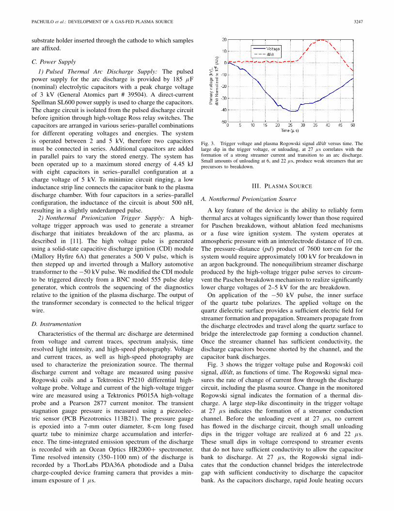
Fig. 3. Trigger voltage and plasma Rogowski signal dI/dt versus time. Thelarge dip in the trigger voltage, or unloading, at 27 μs correlates with theformation of a strong streamer current and transition to an arc discharge.Small amounts of unloading at 6, and 22 μs, produce weak streamers that areprecursors to breakdown.
III. PLASMA SOURCE
A. Nonthermal Preionization Source
A key feature of the device is the ability to reliably formthermal arcs at voltages significantly lower than those requiredfor Paschen breakdown, without ablation feed mechanismsor a fuse wire ignition system. The system operates atatmospheric pressure with an interelectrode distance of 10 cm.The pressure–distance (pd) product of 7600 torr·cm for thesystem would require approximately 100 kV for breakdown inan argon background. The nonequilibrium streamer dischargeproduced by the high-voltage trigger pulse serves to circum-vent the Paschen breakdown mechanism to realize significantlylower charge voltages of 2–5 kV for the arc breakdown.
On application of the −50 kV pulse, the inner surfaceof the quartz tube polarizes. The applied voltage on thequartz dielectric surface provides a sufficient electric field forstreamer formation and propagation. Streamers propagate fromthe discharge electrodes and travel along the quartz surface tobridge the interelectrode gap forming a conduction channel.Once the streamer channel has sufficient conductivity, thedischarge capacitors become shorted by the channel, and thecapacitor bank discharges.
Fig. 3 shows the trigger voltage pulse and Rogowski coilsignal, dI/dt, as functions of time. The Rogowski signal mea-sures the rate of change of current flow through the dischargecircuit, including the plasma source. Change in the monitoredRogowski signal indicates the formation of a thermal dis-charge. A large step-like discontinuity in the trigger voltageat 27 μs indicates the formation of a streamer conductionchannel. Before the unloading event at 27 μs, no currenthas flowed in the discharge circuit, though small unloadingdips in the trigger voltage are realized at 6 and 22 μs.These small dips in voltage correspond to streamer eventsthat do not have sufficient conductivity to allow the capacitorbank to discharge. At 27 μs, the Rogowski signal indi-cates that the conduction channel bridges the interelectrodegap with sufficient conductivity to discharge the capacitorbank. As the capacitors discharge, rapid Joule heating occurs

3248 IEEE TRANSACTIONS ON PLASMA SCIENCE, VOL. 42, NO. 10, OCTOBER 2014
Fig. 4. High-speed image of streamers formed inside the plasma chamber.In this photograph, the gas inlet and anode are on the left; the cathode is onthe right. The feed gas is argon.
TABLE I
IGNITION THRESHOLD AND ARC DELAY DEPENDENCE ON CHARGE
VOLTAGE FOR ARGON BACKGROUND
that leads to gas expansion and formation of an audibleshockwave. The large current densities and high pressuresresult in a highly collisional plasma that is in thermodynamicequilibrium.
Fig. 4 shows an array of streamers inside the plasmachamber formed by the high-voltage trigger pulse. The stream-ers are highly branched, following a contorted path as theypropagate in the discharge volume. The streamer array gen-erates a volumetric source of seed electrons that providessufficient ionization for thermal arc breakdown. The brighteststreamer emission is observed at the left electrode, regard-less of polarity. Enhanced light emission near the left elec-trode is due to asymmetry in the geometry of the electrodeconfiguration. The left electrode protrudes 10 mm into thereaction chamber decreasing the breakdown threshold poten-tial, whereas the right electrode is flush with the chamberexit.
The ignition threshold potential for a streamer that leads tothe formation of a thermal arc depends on the applied potentialacross the main discharge electrodes. As the main interelec-trode charge potential increases for an argon background, thetrigger ignition threshold voltage for thermal arc formationdecreases. Ignition threshold voltages may be defined as thevoltage of the trigger pulse at which sufficient preionizationhas occurred to induce a thermal arc breakdown. The appliedinterelectrode potential reduces the required ignition voltage,and therefore, decreases the delay time for thermal arc forma-tion for an argon background. Table I lists the ignition thresh-old voltages and transition to arc delay times as a function ofcharge voltage in an argon background. A charge voltage of 1.6kV is the lowest potential for which breakdown was recorded.The dash indicates thermal breakdown is not reliable and theignition threshold voltage occurred after the peak of triggerpulse.
TABLE II
RANGE OF OPERATING CONDITIONS WITH
99.5% PURE ARGON FEED GAS
Fig. 5. Voltage, current, and light emission of the plasma at typicalconditions.
B. Thermal Plasma Arc Discharge
The pulsed thermal plasma discharge source operates overa range of conditions. The high pressure, and therefore thecollisionality, regulates the plasma temperature to approxi-mately 1–2 eV. The plasma temperature is relatively insensitiveto the stored capacitive energy, therefore various capacitorconfigurations will alter the RC time constant and fluidicresponse even though plasma properties remain uniform.
The discharge has been operated with plasma durations of40–140 μs, and with energies from 85 J to 3 kJ. Table IIsummarizes conditions for 99.5% purity argon plasma at thelowest and highest energies we have operated the device, withtypical conditions in the middle column. The lower limit ofoperation is set by the minimum voltage at which breakdownis possible.
In high-power configurations, a shock wave is generatedby rapid Joule heating. The sudden and large overpressurecan fracture the quartz tube and destroy the test samples.The upper limit of operation of 150 MW is determinedby mechanical failure of the chamber. A majority of theplasma/surface interaction studies were conducted at typicalconditions. Typical conditions correspond to four capacitorsarranged in a series–parallel configuration, charged to 3.2 ±0.1 kV with argon flowing at 45 ± 2 SLPM.
Fig. 5 shows typical normalized voltage, current, and lightintensity waveforms for breakdown in 99.5% pure argon usingfour capacitors at 3.2 kV. Voltage and current traces are under-damped at typical operating conditions, and the light intensity

PACHUILO et al.: DEVELOPMENT OF A GAS-FED PLASMA SOURCE 3249
TABLE III
OBSERVED LINES AND ASSOCIATED ENERGY LEVELS FOR 99.5% PURE
ARGON PLASMA AT TYPICAL OPERATING CONDITIONS
waveform lags the current. The light emission continues at alow level after the plasma current has reached zero.
C. Emission Spectra of the Thermal Discharge
Time integrated emission spectra of the discharge wererecorded by the Ocean Optics spectrometer with a wavelengthrange from 200 to 1000 nm. The plasma was viewed with anoptical fiber and lens that looked either across the diameterof the plasma source (L ∼ 32 mm) or along the length(L ∼ 100 mm) of the chamber. The light emission from theplasma source was dominated by lines of neutral Ar I andionized Ar II. In addition, emission lines from silicon andhydrogen (Hα) were also observed. Table III summarizes theobserved lines and associated energy levels for the argon arcat typical operating conditions.
Plasma temperatures were estimated between 1 and 2 eVassuming a Boltzmann equilibrium distribution for all excitedspecies. The equilibrium Boltzmann assumption is valid forpressures of ∼105 Pa and ionization ratios of ∼10−3 [12]. Thespectrum of the discharge for typical operating conditions isshown in Fig. 6.
Some discharges showed line radiation from silicon neutralatoms in the spectral region λ ∼ 250 nm. Silicon neutral linesin the spectrum indicate ablation of the quartz chamber walls.
Fig. 6. Corrected emission spectrum in the wavelength range of 200–1000 nmfor Ar + 2%H2 discharge at 4 kV. The observed dominant emission lines ofAr I, Ar II, Ar III, H, and Si II are seen in the spectrum. Electron temperature(Te) estimated from the intensity of emission line ratios using the Boltzmannplot method.
Surface analysis of the quartz chamber wall and test materialsconfirmed the presence of silicon from the plasma chamber.The ablation of silicon from the quartz wall is discussed inmore detail in Section IV.
In all spectra, the radiated power was dominated by lineradiation. Optical depth considerations were important whenanalyzing the plasma spectra because the device operates ina high-density and high-pressure regime. Stark broadeningof argon ion lines was too small to be resolved with theOcean Optics spectrometer. With the addition of a smallamount of hydrogen, time-averaged measurements of electronnumber density from the Stark broadened hydrogen lines wereestimated to be ne ∼ 1023 m−3.
D. Time Evolution of the Thermal Plasma Discharge
High-speed imaging has provided additional insights intothe plasma evolution. The most important findings are: 1) theplasma discharge is constricted and does not occupy theavailable chamber volume and 2) multiple arcs can form, witha high degree of randomness to their shape. Consequently,there is significant shot-to-shot variation in how the core ofthe plasma interacts with samples in the reaction chamber.
Fig. 7(a) and (b) shows high-speed image sequences fortwo separate shots of the arc discharge. Fig. 7(a) shows atime evolution of the plasma arc discharge. The arc initiallyexhibits multiple branched filaments from the anode (left) at10 μs. The arc filaments attach and track along the surface ofthe alumina sample-holder to the cathode. At 35 μs the arcfilaments have coalesced into a single diffuse arc discharge.Fig. 7(b) shows the time evolution of another constricted arcfilament bridging the interelectrode gap at 10 and 20 μs. Thereis minimal interaction with the sample holder. Initially, thearc occupies a small localized volume. As the current andtemperature rises, the arc volume grows while retaining theinitial geometric configuration.
The images show the high degree of randomness in theinitial formation and development of the arc filament. Oncean arc is formed, the diameter increases until the arc occupies

3250 IEEE TRANSACTIONS ON PLASMA SCIENCE, VOL. 42, NO. 10, OCTOBER 2014
Fig. 7. High-speed photography of the thermal arc discharge in argon.(a) Time evolution of filamentary branching and surface tracking along thesample holder at 10 μs, and growth of the filamentary arc at 35 μs. (b) Timeevolution of the constricted plasma arc filament that does not interact withthe sample holder at 10 and 20 μs.
Fig. 8. 10× photomicrographs taken with a Nikon Optiphot 100 of (a) siliconand (b) sapphire showing deposits of copper from early tests using brasselectrodes. Similar samples tested with Elkonite electrodes show no evidenceof copper.
approximately a quarter of the chamber volume. Modificationsto the design of the plasma chamber are likely required tocreate uniform and voluminous arcs that interact strongly withthe samples. We are presently investigating smaller diameterreaction chambers where the quartz tube surface itself betterdefines and stabilizes the arc.
IV. INTERACTION OF HIGH-DENSITY PLASMA WITH
SILICON AND SAPPHIRE SAMPLES
Presently, the device has been used to study the interactionof thermal plasmas with silicon, alumina, and sapphire testsamples orientated orthogonal to the flow. Initial studies wereconducted using a brass anode and a steel cathode. In thosestudies, the samples became coated with copper from theanode, as shown in Fig. 8(a) and (b). To decrease electrodematerial deposition on test samples, electrodes were fabricatedfrom Elkonite 50W3, an infiltrated 10% copper and 90%tungsten contact material. The high-melting temperature oftungsten prevents evaporation of electrode material, when thearc is in contact with the surface. Copper possesses high
Fig. 9. 10× magnification photomicrographs of (a) brass and (b) Elkoniteelectrodes after several hundred tests. The brass shows gross removal ofmolten material.
Fig. 10. (a) Surface of single-crystal sapphire showing an abundance ofsilicon deposited onto the sample. The arrow indicates where scratching ofthe surface exposed the sapphire substrate. (b) EDXS analysis of the sampleconfirming the presence of (I) carbon, (II) oxygen, (III) aluminum, and (IV)silicon.
thermal and electrical conductivity that allow large currentsto flow and reduce local thermal loadings.
Before testing, the electrodes needed be conditioned. About50 shots were required to evaporate the copper from thesurface leaving only the tungsten. Fig. 9 compares the surfaceof the brass and Elkonite anodes. As expected, the brass showsevidence of gross melting from the arc, whereas the Elkoniteshows only small spots that are presumably arc attachmentspots on the Elkonite surface.
Evaporated silicon from the wall of the quartz chamberpresented a second source of contamination. Silicon depositswere observed on the test samples. The quartz chamber andtest samples were analyzed with a Hitachi S-4700 high-resolution SEM equipped with an Oxford Instruments EDXSmicroanalysis system. Fig. 10(a) shows an SEM photographof a single-crystal sapphire sample after 15 exposures to theplasma. The sample was coated with a fine dusting of siliconparticles with an average particle size of 30–40 nm. At thecenter of the photograph is an area that was gently touchedwith the edge of a set of fine tweezers, revealing the sapphiresubstrate that appears similar to the surface of unexposedsapphire. EDXS analysis of the sample, as shown in Fig. 10(b),confirms there was a significant amount of silicon on thesurface of the sample as well as trace amounts of carboncontamination.

PACHUILO et al.: DEVELOPMENT OF A GAS-FED PLASMA SOURCE 3251
Fig. 11. (a) Plasma quartz chamber after almost 300 exposures. Left: thedamaged part of the fused quartz was nearest to the anode, whereas the cathodeend of the tube showed no damage (a small ring of discoloration on thecathode side is on the exterior of the tube, caused by the decomposition of anO-ring). (b) SEM analyses of the surface near the anode show an abundanceof spheroidal holes. (c) SEM analysis of a chipped edge, also by the anode,shows that the depth of the affected zone is about 3.3 μm.
Fig. 11 shows a section of the quartz plasma chamber thatwas removed after approximately 300 exposures. The chamberwas exposed to argon plasma at a charge voltage of 3.2 kV. Theinterior of the chamber closest to the gas inlet electrode (anodefor this test sequence) was discolored and slightly opaque [leftportion of quartz chamber Fig. 11(a)], whereas practicallyno damage was observed at the gas outlet [or cathode, rightportion quartz chamber Fig. 11(a)]. SEM analysis of thesample from the damaged region showed the surface to containa number of spheroidal pores on the order of 1 μm indiameter, as shown in Fig. 11(b). Analysis of a cleaved crosssection, as shown in Fig. 11(c), showed three distinct zones:number 1 is the boundary between the unaffected quartz andthe reacted zone above, number 2 indicates a vitrification zone,and number 3 indicates a highly porous zone.
The damaged zone extends approximately 3.2–3.4 μm intothe inner surface of the quartz chamber. Cross-sectional analy-sis from samples on the cathode side of the chamber did notshow any damage. EDXS analysis of the quartz chamber anoderegion showed a significant silicon deficiency with respectto the control. Carbon contamination was also documentedwith EDXS that corresponds to the discoloration observed inFig. 11(a). To prevent silicon deposition on test materials dueto the accumulation of damage, the plasma chamber must bereplaced after 100 exposures.
Several factors have been proposed to explain the asymmet-rical erosion of the plasma chamber. These include polarity ofthe electrodes, orientation of the trigger wire, and proximity ofthe gas inlet electrode to the chamber wall. Reversing polarityof the electrodes does not change the erosion pattern; erosionstill occurs at the gas inlet side of the reaction chamber.Similarly, reversing the orientation of the trigger wire did notchange the location of the damage. Damage of the quartzchamber is likely due to the protrusion of the gas inletelectrode and the associated enhancement of the electric fieldson this electrode.
V. CONCLUSION
A gas-fed plasma source has been developed to study howpulsed, high-density plasmas interact with materials. Plasmaparameters for the pulsed atmospheric thermal discharge weredetermined, including the estimated electron temperature usingthe Boltzmann plot method, Te ∼ 1–2 eV, and the estimatedelectron number density, ne ∼ 1017 cm−3. The electrontemperature and density are within the expected regime forhigh-density LTE discharges.
The use of feed gases to form the plasma arc provides ahigher degree of control over the plasma composition thancan be achieved using consumable liners and exploding fusewire systems. Although a high degree of control of the plasmachemistry and minimization of contaminant materials hasbeen achieved in the gas-fed plasma chamber, electrode, andchamber wall deterioration was observed. Contamination fromthe electrodes was minimized using Elkonite 50W3 as theelectrode material. Elimination of the quartz chamber wallerosion is difficult due to high-thermal loads and localizedstreamer surface tracking. High-speed images of streamers andarcs show that the damage to the walls correlates strongly withthe location of streamers between the gas inlet electrode andtrigger wire.
High-speed imaging has also shown a high degree of vari-ability in the arc formation. Arcs typically evolve to occupyabout a quarter of the reaction chamber volume. Consequently,there is a large shot-to-shot variation in how the plasma coreinteracts with samples. The random shape of the arc column isa consequence of the random nature of the streamers and thelarge chamber volume. Although the arc structure is random,the current, light intensity, pressure, and emission spectra arehighly reproducible.
The gas-fed plasma source that has been developed providesa controllable environment for material interaction investi-gations and the ability to reliably breakdown at pressure–distance products exceeding the Paschen breakdown threshold.The novel triggering approach provides reliable ignition thatdoes not require the use of ablative liners or exploding wireignition techniques that would contaminate the system aswell as reduce throughput. The plasma device is ideal forhighly controllable, low contamination, and plasma–materialinteraction studies.
ACKNOWLEDGMENT
The authors would like to thank S. Rojani and E. Trevinofor their help.

3252 IEEE TRANSACTIONS ON PLASMA SCIENCE, VOL. 42, NO. 10, OCTOBER 2014
REFERENCES
[1] E. Stuhlinger, “Electric space propulsion systems,” Space Sci. Rev.,vol. 7, nos. 5–6, pp. 795–847, Dec. 1967.
[2] L. L. Raja, P. L. Varghese, and D. E. Wilson, “Modeling of theelectrogun metal vapor plasma discharge,” J. Thermophys. Heat Transf.,vol. 11, no. 3, pp. 353–360, Jul./Sep. 1997.
[3] P. J. Wilbur, R. G. Jahn, and F. C. Curran, “Space electric propulsionplasmas,” IEEE Trans. Plasma Sci., vol. 19, no. 6, pp. 1167–1179,Dec. 1991.
[4] A. Gleizes, J. J. Gonzalez, and P. Freton, “Thermal plasma modelling,”J. Phys. D, Appl. Phys., vol. 38, no. 9, pp. R153–R183, Apr. 2005.
[5] E. Ahedo, “Plasmas for space propulsion,” Plasma Phys. ControlledFusion, vol. 53, no. 12, pp. 124037–124054, Nov. 2011.
[6] M. I. Boulos, “Thermal plasma processing,” IEEE Trans. Plasma Sci.,vol. 19, no. 6, pp. 1078–1089, Dec. 1991.
[7] L. Pekker and O. Pekker, “Model of high-pressure ablative capillarydischarge for plasma thrusters,” J. Propuls. Power, vol. 27, no. 2,pp. 477–484, Mar./Apr. 2011.
[8] C. B. Ruchti and L. Niemeyer, “Ablation controlled arcs,” IEEE Trans.Plasma Sci., vol. 14, no. 4, pp. 423–434, Aug. 1986.
[9] D. E. Wilson, K. Kim, and L. L. Raja, “Theoretical analysis ofan external pulsed plasma jet,” IEEE Trans. Magn., vol. 35, no. 1,pp. 228–233, Jan. 1999.
[10] J. D. Powell and A. E. Zielinski, “Capillary discharge in the electrother-mal gun,” IEEE Trans. Magn., vol. 29, no. 1, pp. 591–596, Jan. 1993.
[11] W. R. Hook, R. H. Dishington, and R. P. Hilberg, “Xenon flashlamptriggering for laser applications,” IEEE Trans. Electron Devices, vol. 19,no. 3, pp. 308–314, Mar. 1972.
[12] X.-M. Zhu and Y.-K. Pu, “Optical emission spectroscopy inlow-temperature plasmas containing argon and nitrogen: Determinationof the electron temperature and density by the line-ratio method,”J. Phys. D, Appl. Phys., vol. 43, no. 40, p. 403001, Sep. 2010.
Authors’ photographs and biographies not available at the time of publication.