Embed Size (px)
Citation preview

Title: Impact Analysis of BIM Spread on Mechanical Design Process
Authors: Kyosuke Hiyama, Yamaguchi UniversityYunting Diao, Azbil CorporationShinsuke Kato, University of TokyoMakoto Koganei, Yamaguchi University
Subject: IT/Computer Science/Software
Keyword: BIM
Publication Date: 2013
Original Publication: International Journal of High-Rise Buildings Volume 2 Number 2
Paper Type: 1. Book chapter/Part chapter2. Journal paper3. Conference proceeding4. Unpublished conference paper5. Magazine article6. Unpublished
© Council on Tall Buildings and Urban Habitat / Kyosuke Hiyama; Yunting Diao; Shinsuke Kato; MakotoKoganei
ctbuh.org/papers

International Journal of High-Rise Buildings
June 2013, Vol 2, No 2, 97-104International Journal of
High-Rise Buildingswww.ctbuh-korea.org/ijhrb/index.php
Impact Analysis of BIM Spread on
Mechanical Design Process Based on
Consciousness Survey among Japanese Mechanical Engineers
Kyosuke Hiyama1, Yunting Diao2, Shisuke Kato3, and Makoto Koganei1
1Faculty of Engineering, Yamaguchi University, Japan2Azbil Corporation, Japan
3Institute of Industrial Science, the University of Tokyo, Japan
Abstract
Recently, the demand for Building Information Modeling (BIM) construction drawings and specifications has increasedrapidly. Many countries have also started to implement BIM. The BIM implementation can change the design flow of buildingsincluding high-rise buildings. Against this background, many companies are focusing on the development of BIM software.BIM involves a three-dimensional CAD program that can examine the placement of ductwork and machinery. It significantlyincreases the efficiency of a mechanical design through data unification using standard Industry Foundation Classes (IFC). Inaddition, BIM functions as a database to simplify the use of simulation technology for designing air-conditioning systems. Tofurther develop BIM, it is important to know the expectations of mechanical engineers who will become frequent users of BIMin the future. A survey was conducted among Japanese mechanical engineers using a questionnaire to analyze the expectationsof mechanical design using BIM. The results show that many respondents strongly recognize BIM as a three-dimensional CADprogram. However they also expect that BIM can help the optimization of their design works and enhance design functionalityby running simulations utilizing BIM.
Keywords: BIM, Consciousness survey, Mechanical engineer
1. Introduction
In recent years, growing attention has been paid to
Building Information Modeling (BIM). The General Ser-
vice Administration (GSA) in the USA has adopted BIM
as a real estate general service (U.S. GSA, 2007). Like-
wise, Wisconsin and Texas use BIM for public buildings.
It is also used in Singapore for applications in building
certification. BIM has been adopted in many projects all
over the world (Hooper and Ekholm, 2010; Hitchmough
et al., 2011; Gu and London, 2010). The Ministry of Land,
Infrastructure, Transport and Tourism (MLIT) in Japan
asked to use BIM for a government office building in
2010; thus, it is expected that the use of BIM for archi-
tectural design will certainly increase in the future in
Japan. BIM is known as a three-dimensional Computer-
Aided Design (CAD) program and as a way of imple-
menting data unification based on standard Industrial
Foundation Classes (IFC) data (Björk and Laakso, 2010).
Likewise, research on and development of BIM as an
information/database tool to improve the efficiency of the
design process is currently underway. The U.S. Green
Building Council (USGBC) proposes to make the Lea-
dership in Energy and Environmental Design (LEED) rat-
ing system more efficient by using BIM (Azhar and Carl-
ton, 2011). In a similar manner, the Comprehensive Assess-
ment System for Built Environment Efficiency (CASBEE)
research and development committee of Japan Sustainable
Building Consortium formed a CASBEE-BIM support
work group to research the use of BIM in automating the
CASBEE ratings process (Iwamura et al., 2010). The So-
ciety of Heating, Air-Conditioning and Sanitary Engineers
of Japan created a BIM/CFD (Computational Fluid Dyna-
mics) modularization subcommittee. To widely spread the
use of thermal load calculation and airflow simulation in
mechanical design, which was previously performed ma-
nually, they have investigated modularizing using sampl-
ing boundary conditions and air-conditioning information
from BIM (Kono et al., 2011). BIM is expected to help the
implementation of simulations at each design stage to
optimize the building design (Diao et al., 2011).
Improving the functionality of mechanical designs requi-
res detailed CFD analysis and system simulations. How-
ever, because it requires intricate data entry, its use is
limited to small parts of a project. Time will be saved in
data entry by adopting BIM and using this technology
more frequently and widely. Mechanical designs develo-
ped using BIM can improve quality and decrease their
†Corresponding author: Kyosuke HiyamaTel: +81-836-85-9711E-mail: [email protected]

98 Kyosuke Hiyama et al. | International Journal of High-Rise Buildings
impact on the environment. As a result, we hope this will
provide an opportunity to significantly improve mecha-
nical design in the whole architectural design field.
To advance research and promote BIM, understanding
the expectations of designers and engineers who design
air-conditioning systems via BIM is required. This paper
reviews the results of a survey questionnaire given to
mechanical engineers in Japan (Hiyama, 2011b) and exa-
mines the direction of BIM research and the development
for mechanical design with discussions including cross
tabulation which concerns different roles in the design
process.
2. Summary of BIM and the Importance in Mechanical Design
BIM is an architectural modeling process that generates
three-dimensional information about objects using CAD
(Singh et al., 2011). By using BIM, it is possible to create
a virtual building that is a mirror image of an actual
building in a virtual space. Because this technology is
object-oriented, the model produced is easily understood.
Thus, BIM output has the advantage of providing intelli-
gible information to a client who does not have any pro-
fessional knowledge. Previous design processes required
coding from a two-dimensional drawing plan to construc-
tion drawings and specifications. Using BIM, it is possi-
ble to model a collection of three-dimensional objects
directly. In other words, in conventional design processes,
a three-dimensional existing building image is first pro-
jected onto two-dimensional documents such as a ground
plan and an elevation at the design stage, and is recon-
structed onto three-dimensional real building at the cons-
truction stage. BIM, however, makes it possible to directly
draw a three dimensional building image as it is. With
object-oriented features, it is easy to unify design elements
of a model or treat them separately. Architectural design
requires documents creation for each division, such as
design, structure, and equipment in parallel. Then the
function is great potential for improving productivity. Be-
cause all design documents share IFC data, information
succession can be performed smoothly from design to
construction. Furthermore it can be probably extended to
future building management. With the three-dimensional
CAD function, it is easy to detect problems causing inter-
ference of objects at the early design stage. This can reduce
the labor of modifying an inconsistent design at the con-
struction stage. Especially, BIM is expected to reduce the
labor of design process for buildings with multiple stories
based on the typical floor plan like high-rise buildings.
The introduction of BIM will bring many benefits to
each field, architectural design, construction, and opera-
tion management. Moreover we especially expect it to be
a great benefit for the mechanical design field. Generally,
a mechanical design plan is created by overlaying archi-
tectural drawings. In addition, a construction plan is re-
quired to examine the placement of piercing beams. For
system examination, information from other divisions is
very important in calculating the thermal load. Because of
their importance to mechanical design, architectural de-
signs, construction plans, and electrical equipment plans
need to be updated continuously in the early design
stages.
Furthermore, by adopting BIM, it is possible to improve
the functionality of mechanical design to meet the various
requests of clients. This may highlight the significance of
mechanical design in the whole architectural design pro-
cess. A mechanical engineer’s job is not only to secure a
comfortable indoor thermal environment on an extremely
hot day of summer (and an extremely cold day of winter)
but also to improve energy savings and productivity. To
achieve this mission, it is necessary to possess advanced
simulation technology, such as system simulation or CFD
analysis (Pratt and Bosworth, 2011; Hiyama et al., 2010,
2011a). However, simulation technology is not widely
used because it requires intricate data entry. By making
data entry efficient through BIM, optimized designs based
on finely calculated models with these simulations will be
generated. Moreover, the time used to communicate with
other divisions (design, construction, and electricity) and
create drawings and specifications by using two-dimen-
sional CAD can be reduced. The reduced time can instead
be spent for improving design functionality or system
examinations.
Because environmental impact is an important consi-
deration today, a mechanical engineer must have the abi-
lity to come up with an optimized plan based on detailed
analysis (Suga et al., 2010). In recent years, investments
in building utilities in Japan have tended to be valued not
only for direct benefits, such as the budgetary reduction
of running costs, but also for indirect benefits, such as
environmental considerations and health improvements.
Clients’ demands of a mechanical engineer are diverse as
well. With the high credibility of detailed simulations, it
is possible to provide a client with information that could
not be shown in conventional design documents using
two-dimensional documents. Thus, having utilizing BIM
will make a big difference in a company’s merits. It is
also possible to show information to a client much more
easily using three-dimensional CAD. A client’s impression
changes immeasurably by depicting a physical environ-
ment, such as a flow distribution or temperature field. It
influences the quality of architectural design, depending
on whether engineers have these skills or not. Thus, BIM
is expected to enhance the importance of mechanical
engineers by allowing them to play an important role in
architectural design.
3. Summary of a Questionnaire
Table 1 shows the select review of the questionnaire
(See previous literature (Hiyama, 2011b) for the entire

Impact Analysis of BIM Spread on Mechanical Design Process Based on Consciousness Survey among Japanese Mechanical Engineers 99
Table 1. Content of Questionnaire (select review)
- Question about usual design work.
Q1. How much (in percentage) do you use the below-mentioned technical computing for your design? Please tell us theestimate for roughly the last one year (e.g., Used on half of all projects = 50%)
i. Energy Simulation (Annual thermal load calculation)ii. System Simulationiii. LCA (Life Cycle Assessment: LCCO2 etc.)iv. Construction Environmental Efficiency Rating (CASBEE etc.)v. CFD Analysis
Q2. Please choose the most applicable among the listings below of your reasons to use the 3D indoor environment estima-tion tool (Multiple answers allowed.)
- To optimize for a comfortable thermal environment- To optimize the air flow (designs for natural ventilation)- To ensure against creating an uncomfortable thermal environment- To optimize the outdoor wind environment (securing cool outdoors breezes)- To ensure against creating a windy zone (building-induced wind)- To create explanatory documents corresponding to a client’s request- Because of company and group policy- Unknown because not used
Q3. Which one from the list below should be applied to optimize designs (to improve design quality)? (Multiple answersallowed)
- Energy Simulation (Annual thermal load calculation)- System Simulation- LCA (Life Cycle Assessment)- Construction Environmental Efficiency Rating (CASBEE etc.)- CFD Analysis- None
Q4. How much labor do you use for one design project? Please answer with rough percentages (please include calcula-tions and designs for outside orders.)
- Preliminary design / Concept design- Schematic design- Detailed design
Q5. How much labor do you use for one schematic designing? Please answer with rough percentages.
- System examination, Decision making for facility system, Summary of schematic design- Correspondence to clients, Office negotiation- Coordination with other design teams (Architectural, Construction, and Electricity)
Q6. How much labor do you use for one detailed designing? Please answer with rough percentages. (please include cal-culations and designs for outside orders.)
- Detailed design calculation- Creating detailed design plan- Correspondence to clients, Office negotiation- Coordination with other design team (Architectural, Construction, and Electricity)
- Question about BIM (Building Information Modeling)Definition of BIM: It is a database of a digitalize 3D building accompanied with attribution data, such as machinery parts andmaterials data. Today, some software programs are available on the market that can make it possible to automate thermal loadcalculation and verify the error and problems in overlaying architectural/constructed/facility models.
Q8. Please choose therr from the list below that you think provide the best advantege in using BIM for facility designs.
- It is possible to examine the placement of ductwork/piping and the machinery room. Also, it is easy to check design errors inadvance.- It can secure integrity and consistency for design works, design drawings, and specifications, as BIM automatically creates thedesign dreawing and specification during the design process.- It reduces the labor in data entry for thermal load calculation.- It reduces the labor in data entry for construction efficiency rating tools, such as CASBEE.- It facilitates integration (picking up) or creating an operation plan.- It makes communication between the project team smooth.- It can be used for a design presentation to a client.- It can be used for facility management.
Q9. Assume that the BIM software listed below exists on the market. Please choose one of the BIM products that youwould to use most and a secondary product you would want to use.
Product 1: Automation of ductwork placement and energy simulationProduct 2: Automation of ductwork placement and CFD analysisProduct 3: Automation of CFD analysis and energy simulation
100 Kyosuke Hiyama et al. | International Journal of High-Rise Buildings
questionnaire). Q1, Q2, and Q3 contain questions related
to the present use of simulation technology and the ex-
pectation for its future use. It is important to clarify the
cost and effect when considering the implementation of
BIM. Thus, Q4, Q5, and Q6 contain questions related to
the present allocation of labor in the design process, which
helps analyze the cost and effect. With the implementa-
tion of BIM, smooth communication between the person
in charge of architectural design and construction, the
elimination of time spent coding two-dimensional plans,
and the automation of simulation data entry can be ex-
pected. These questions intend to fully capture effective
ways of improving the productivity of the design process
fully. Q8, and Q9 ask for desired functions utilizing BIM.
The questionnaire was filled online, and the URL was
sent to companies with Mechanical Electrical Plumbing
(MEP) design facilities. The respondents were limited to
mechanical engineers. The period of the questionnaire
was 15 days, from July 1st to 15th 2010.
4. Result and Analysis
4.1. Respondents’ attributes
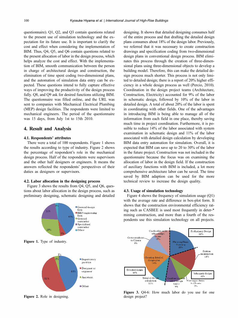
There were a total of 100 respondents. Figure 1 shows
the results according to type of industry. Figure 2 shows
the percentage of respondent’s role in the mechanical
design process. Half of the respondents were supervisors
and the other half designers or engineers. It means the
answers reflected the respondents’ perspectives of their
duties as designers or supervisors.
4.2. Labor allocation in the designing process
Figure 3 shows the results from Q4, Q5, and Q6, ques-
tions about labor allocation in the design process, such as
preliminary designing, schematic designing and detailed
designing. It shows that detailed designing consumes half
of the entire process and that drafting the detailed design
plans consumes about 18% of the design labor. Previously,
we referred that it was necessary to create construction
drawings and specification coding from two-dimensional
design plans in conventional design process. BIM elimi-
nates this process through the creation of three-dimen-
sional plans using three-dimensional objects to develop a
building model. Therefore, this can make the detailed de-
sign process much shorter. This process is not only limi-
ted to detailed design; there is a report of 20% higher effi-
ciency in a whole design process as well (Percio, 2010).
Coordination in the design project teams (Architecture,
Construction, Electricity) accounted for 9% of the labor
in schematic design, followed by 10% of the labor in
detailed design. A total of about 20% of the labor is spent
in coordinating with other fields. One of the advantages
in introducing BIM is being able to manage all of the
information from each field in one place, thereby saving
much time in project coordination. Furthermore, it is po-
ssible to reduce 14% of the labor associated with system
examination in schematic design and 11% of the labor
associated with detailed design calculation by developing
BIM data entry automation for simulation. Overall, it is
expected that BIM can save up to 20 to 30% of the labor
in the future project. Construction was not included in the
questionnaire because the focus was on examining the
allocation of labor in the design field. If the construction
of auxiliary functions with BIM is included, a lot more
comprehensive architecture labor can be saved. The time
saved by BIM adaption can be used for the more
technical review to increase the design quality.
4.3. Usage of simulation technology
Figure 4 shows the frequency of simulation usage (Q1)
with the average rate and difference in box-plot form. It
shows that the construction environmental efficiency rat-
ing such as CASBEE is used most frequently in deter-*
mining construction, and more than a fourth of the res-
pondents use this simulation technology on all projects.
Figure 2. Role in designing.
Figure 1. Type of industry.
Figure 3. Q4-6: How much labor do you use for onedesign project?

Impact Analysis of BIM Spread on Mechanical Design Process Based on Consciousness Survey among Japanese Mechanical Engineers
Energy simulation comes second in the list, followed by
system simulation, LCA (Life Cycle Assessment), and
CFD analysis. Although some answered that they use LCA
and CFD analysis on all projects, three-fourths of the res-
pondents showed indicated 30% usage. CASBEE, which
utilizes Excel, or Energy simulation, which is in high de-
mand, require comparatively less data entry labor. CFD
analysis requires more intricate data entry (creating three-
dimensional models) than other simulations.
Although it changes according to clients’ demands and
it is difficult to infer simply, the frequency of simulation
use seems to drop significantly with more intricate data
entry. Figure 5 shows the results from Q3 concerning the
expectations from using simulations in the future. CFD
analysis received the most interest, followed by system
simulation and energy simulation. Compared to LCA (both
LCA and CFD analysis showed low usage in Q1), CFD
analysis has hope for design optimization, even with intri-
cate data entry. Using BIM to automate data entry for CFD
analysis has great potential. Because there was high usage
reported in the construction environmental efficiency rat-
ing in Q1, its result for future usage was low.
Figure 6 displays the reasons for using three-dimensio-
nal indoor environmental estimation tools such as CFD
analysis (Q2). A large amount of respondents indicated
that it is useful in presenting a design to a client, followed
by thermal environmental analysis, natural ventilation,
and indoor environmental analysis. It was also shown that
it is rare for mechanical engineers to analyze the outdoor
wind environment. To promote CFD analysis in projects,
it is important to demonstrate that BIM is useful in visu-
alizing designs for clients and convenient for analyzing
indoor environments.
4.4. The expectations of facility design engineers for
BIM development
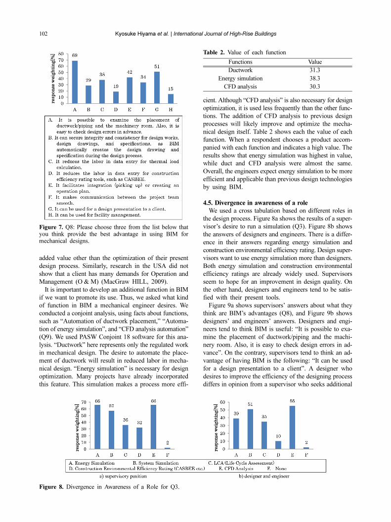
Figure 7 shows the responses to Q8, a question about
what the respondents think the advantages of BIM are. “It
is possible to examine the placement of ductwork/piping
and the machinery room. Also, it is easy to check for
design errors in advance” received the most responses,
followed by “It can be used for a design presentation to
a client”. These two answers came first because the res-
pondents seem to have an idea of BIM as a three-dimen-
sional graphic tool. “It reduces the labor in data entry for
thermal load calculation” and “It facilitates integration
(picking up) or creating an operation plan” ranked next in
importance. BIM might be thought of as a database func-
tion. One of the selections, “It reduces the labor in data
entry for construction efficiency rating tools, such as
CASBEE”, is also a database function. As mentioned
above, because it is already used frequently, it did not
appear as an advantage of using BIM. It also showed that
engineers do not feel that CASBEE data entry constitutes
much of their labor. “It can be used for facility manage-
ment” ranked very low in the results. However, The Ge-
neral Service Administration (GSA) in the USA guide-
lines list facility management as one of BIM’s merits.
Here, the respondents did not demonstrate awareness of
Figure 4. Q1: How much do you use the technical com-puting for your design?
Figure 5. Q3: Which one from the list should be appliedto optimize designs?
Figure 6. Q2: Please choose the most applicable amongthe listings below of your reasons to use the 3D indoorenvironment estimation tool.
102 Kyosuke Hiyama et al. | International Journal of High-Rise Buildings
added value other than the optimization of their present
design process. Similarly, research in the USA did not
show that a client has many demands for Operation and
Management (O & M) (MacGraw HILL, 2009).
It is important to develop an additional function in BIM
if we want to promote its use. Thus, we asked what kind
of function in BIM a mechanical engineer desires. We
conducted a conjoint analysis, using facts about functions,
such as “Automation of ductwork placement,” “Automa-
tion of energy simulation”, and “CFD analysis automation”
(Q9). We used PASW Conjoint 18 software for this ana-
lysis. “Ductwork” here represents only the regulated work
in mechanical design. The desire to automate the place-
ment of ductwork will result in reduced labor in mecha-
nical design. “Energy simulation” is necessary for design
optimization. Many projects have already incorporated
this feature. This simulation makes a process more effi-
cient. Although “CFD analysis” is also necessary for design
optimization, it is used less frequently than the other func-
tions. The addition of CFD analysis to previous design
processes will likely improve and optimize the mecha-
nical design itself. Table 2 shows each the value of each
function. When a respondent chooses a product accom-
panied with each function and indicates a high value. The
results show that energy simulation was highest in value,
while duct and CFD analysis were almost the same.
Overall, the engineers expect energy simulation to be more
efficient and applicable than previous design technologies
by using BIM.
4.5. Divergence in awareness of a role
We used a cross tabulation based on different roles in
the design process. Figure 8a shows the results of a super-
visor’s desire to run a simulation (Q3). Figure 8b shows
the answers of designers and engineers. There is a differ-
ence in their answers regarding energy simulation and
construction environmental efficiency rating. Design super-
visors want to use energy simulation more than designers.
Both energy simulation and construction environmental
efficiency ratings are already widely used. Supervisors
seem to hope for an improvement in design quality. On
the other hand, designers and engineers tend to be satis-
fied with their present tools.
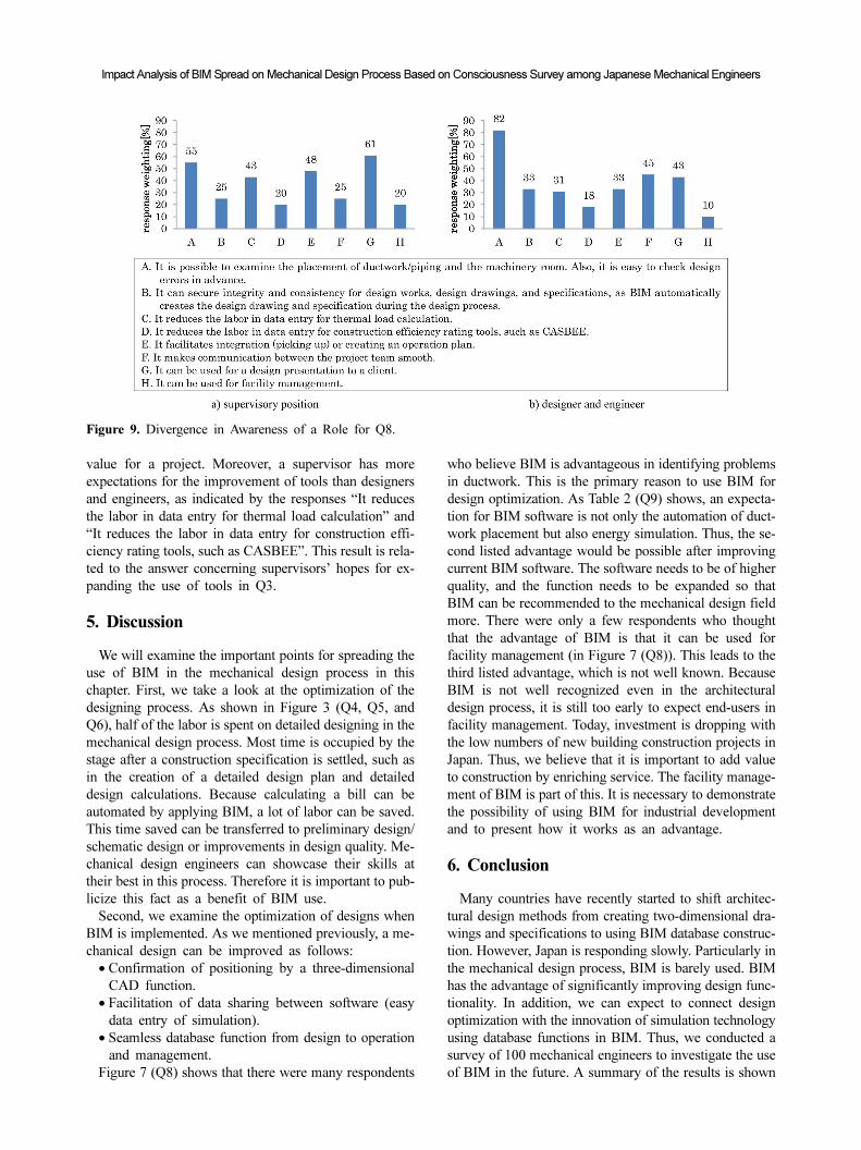
Figure 9a shows supervisors’ answers about what they
think are BIM’s advantages (Q8), and Figure 9b shows
designers’ and engineers’ answers. Designers and engi-
neers tend to think BIM is useful: “It is possible to exa-
mine the placement of ductwork/piping and the machi-
nery room. Also, it is easy to check design errors in ad-
vance”. On the contrary, supervisors tend to think an ad-
vantage of having BIM is the following: “It can be used
for a design presentation to a client”. A designer who
desires to improve the efficiency of the designing process
differs in opinion from a supervisor who seeks additional
Figure 7. Q8: Please choose three from the list below thatyou think provide the best advantage in using BIM formechanical designs.
Table 2. Value of each function
Functions Value
Ductwork 31.3
Energy simulation 38.3
CFD analysis 30.3
Figure 8. Divergence in Awareness of a Role for Q3.
Impact Analysis of BIM Spread on Mechanical Design Process Based on Consciousness Survey among Japanese Mechanical Engineers
value for a project. Moreover, a supervisor has more
expectations for the improvement of tools than designers
and engineers, as indicated by the responses “It reduces
the labor in data entry for thermal load calculation” and
“It reduces the labor in data entry for construction effi-
ciency rating tools, such as CASBEE”. This result is rela-
ted to the answer concerning supervisors’ hopes for ex-
panding the use of tools in Q3.
5. Discussion
We will examine the important points for spreading the
use of BIM in the mechanical design process in this
chapter. First, we take a look at the optimization of the
designing process. As shown in Figure 3 (Q4, Q5, and
Q6), half of the labor is spent on detailed designing in the
mechanical design process. Most time is occupied by the
stage after a construction specification is settled, such as
in the creation of a detailed design plan and detailed
design calculations. Because calculating a bill can be
automated by applying BIM, a lot of labor can be saved.
This time saved can be transferred to preliminary design/
schematic design or improvements in design quality. Me-
chanical design engineers can showcase their skills at
their best in this process. Therefore it is important to pub-
licize this fact as a benefit of BIM use.
Second, we examine the optimization of designs when
BIM is implemented. As we mentioned previously, a me-
chanical design can be improved as follows:
• Confirmation of positioning by a three-dimensional
CAD function.
• Facilitation of data sharing between software (easy
data entry of simulation).
• Seamless database function from design to operation
and management.
Figure 7 (Q8) shows that there were many respondents
who believe BIM is advantageous in identifying problems
in ductwork. This is the primary reason to use BIM for
design optimization. As Table 2 (Q9) shows, an expecta-
tion for BIM software is not only the automation of duct-
work placement but also energy simulation. Thus, the se-
cond listed advantage would be possible after improving
current BIM software. The software needs to be of higher
quality, and the function needs to be expanded so that
BIM can be recommended to the mechanical design field
more. There were only a few respondents who thought
that the advantage of BIM is that it can be used for
facility management (in Figure 7 (Q8)). This leads to the
third listed advantage, which is not well known. Because
BIM is not well recognized even in the architectural
design process, it is still too early to expect end-users in
facility management. Today, investment is dropping with
the low numbers of new building construction projects in
Japan. Thus, we believe that it is important to add value
to construction by enriching service. The facility manage-
ment of BIM is part of this. It is necessary to demonstrate
the possibility of using BIM for industrial development
and to present how it works as an advantage.
6. Conclusion
Many countries have recently started to shift architec-
tural design methods from creating two-dimensional dra-
wings and specifications to using BIM database construc-
tion. However, Japan is responding slowly. Particularly in
the mechanical design process, BIM is barely used. BIM
has the advantage of significantly improving design func-
tionality. In addition, we can expect to connect design
optimization with the innovation of simulation technology
using database functions in BIM. Thus, we conducted a
survey of 100 mechanical engineers to investigate the use
of BIM in the future. A summary of the results is shown
Figure 9. Divergence in Awareness of a Role for Q8.

104 Kyosuke Hiyama et al. | International Journal of High-Rise Buildings
below:
• 19% of labor is used in coordinating with other
design project teams (Architecture, Construction, and
Electricity), 18% in creating a detailed design, 11% in
detailed design calculation, and 14% in system exa-
mination. We estimate 20 to 30% of labor in a whole
design process can be reduced by applying BIM to
streamline these processes.
• Below 20% reported the use of CFD analysis in their
design. However, about 60% reported that to improve
the design process, utilization of CFD analysis is highly
desired for the future. Users can improve the frequency
of using CFD analysis with the efficient data entry
provided by BIM.
• Mechanical engineers understand that the primary ad-
vantage of using BIM is to be able to confirm the place-
ment of ductwork/piping and to provide documents
for a client using three-dimensional functions.
• However, mechanical engineers hope to use more con-
venient design tools, such as energy simulation, more
than the automation of format works, such as the auto-
mation of ductwork placement when BIM can facili-
tate those functions more.
• We can expect that a lot of labor saved by applying
BIM can be transferred to design optimizations based
on sophisticated simulations utilizing BIM.
Acknowledgements
I would like to express my deepest gratitute to Mr. Ken-
taro Suga from Arup Japan, Mr. Makoto Ohura from Auto-
desk, Inc., Dr. Mutsumi Yokoi, Dr. Hikaru Kobayashi, Mr.
Takeshi Ogawa, Mr. Keiko Sugawara from Taisei Corpora-
tion to help for the questionnaire.
References
Azhar, S., Carlton, W. A., Olsen, D. and Ahmad, I. (2011).
“Building information modeling for sustainable design and
LEED® rating analysis.” Automation in Construction, 20,
pp. 217~224.
Björk, B. C. and Laakso, M. (2010). “CAD standardisation in
the construction industry A process view.” Automation in
Construction, 19, pp. 398~406.
Diao, Y., Kato, S. and Hiyama, K. (2011). “Development of
an optimal design aid system based on building informa-
tion modeling.” Building Simulation, 4, pp. 315~320.
Gu, N. and London, K. (2010). “Understanding and facilita-
ting BIM adoption in the AEC industry.” Automation in
Construction, 19, pp. 988~999.
Hitchmough, M., Holden, N., Johnson, M., Kingstone, D.,
Phillip, M., Speakes, N. and Webster, J. (2011). The design
of the co-operative head office, Manchester. Proceedings
of Building Simulation 2011: 12th Conference of Interna-
tional Building Performance Simulation Association, Syd-
ney, Australia.
Hiyama, K., Kato, S. and Ishida, Y. (2010). “Thermal simu-
lation: Response factor analysis using three-dimensional
CFD in the simulation of air conditioning control.”
Building Simulation, 3, pp. 195~203.
Hiyama, K. and Kato, S. (2011a). “Integration of three-
dimensional CFD results into energy simulations utilizing
an advection-diffusion response factor.” Energy & Build-
ings, 43, pp. 2752~2759.
Hiyama, K., Diao, Y. and Kato, S. (2011b). Analysis of in-
fluence on mechanical design process by BIM spread:
Consciousness survey to BIM by questionnaire of mecha-
nical engineer. Transactions of the Society of Heating,
Air-Conditioning and Sanitary Engineers of Japan, 169,
pp. 39~48. (in Japanese)
Hooper, M. and Ekholm, A. (2010). A pilot study, Towards
BIM integration - an analysis of design information ex-
change & coordination. Proceedings of CIB-W78 2010:
27th International Conference, Cairo, Egypt.
Iwamura, K., et al. (2010). Study on Comprehensive Assess-
ment System for Built Environment Efficiency (CASBEE)
Part. 104: Study on development of CASBEE-BIM Con-
nector, ummaries of technical papers of Annual Meeting
Architectural Institute of Japan. D-1, Environmental engi-
neering I: pp. 1037~1038. (in Japanese)
Kono, R., et al. (2011). Integration of BIM and modulari-
zation of elements for CFD in CAE software tools for
architectural environment. Transactions of the Society of
Heating, Air-Conditioning and Sanitary Engineers of Japan,
174, pp. 15~21. (in Japanese)
McGraw_HILL Construction. (2009). Smart Market Report,
The Business Value of BIM.
Percio, S. (2010). Don't Let your BIM Go ‘BOOM!’: Dealing
with the Liability Issues of BIM, BIM Implementation:
An Owner’s Perspective, Ashrae 2010 Winter Conference,
Orland, USA.
Pratt, K. and Bosworth, D. (2011). Parametric Simulation:
Experimental Methods. Proceedings of CHAMPS 2011:
The 8th International Forum and, Workshop on Combined
Heat, Air, Moisture and Pollutant Simulations, Nanjing,
China.
Singh, V., Gu, N. and Wang, X. (2011). A theoretical frame-
work of a BIM-based multi-disciplinary collaboration plat-
form, Automation in Construction, 20, pp. 134~144.
Suga, K., Kato, S. and Hiyama, K. (2010). “Structural analy-
sis of Pareto-optimal solution sets for multi-objective op-
timization: An application to outer window design pro-
blems using multiple objective genetic algorithms.” Buil-
ding and Environment, 45, pp. 1144~1152.
U.S. General Services Administration, Public Building Servi-
ces, Office of the Chief Architect. (2007). GSA BIM Guide
Series 01 BIM Guide Overview, U.S. General Services
Administration.