Embed Size (px)
Citation preview

MAHARASHTRA STATE BOARD OF TECHNICAL EDUCATION (Autonomous)
(ISO/IEC - 27001 - 2005 Certified)
SUMMER – 13 EXAMINATION Subject Code: 12167 Model Answer Page No: 1/ 30
Important Instructions to examiners: 1) The answers should be examined by key words and not as word-to-word as given in the model answer scheme. 2) The model answer and the answer written by candidate may vary but the examiner may try to assess the understanding level of the candidate. 3) The language errors such as grammatical, spelling errors should not be given more Importance (Not applicable for subject English and Communication Skills). 4) While assessing figures, examiner may give credit for principal components indicated in the figure. The figures drawn by candidate and model answer may vary. The examiner may give credit for any equivalent figure drawn. 5) Credits may be given step wise for numerical problems. In some cases, the assumed constant values may vary and there may be some difference in the candidate’s answers and model answer. 6) In case of some questions credit may be given by judgement on part of examiner of relevant answer based on candidate’s understanding. 7) For programming language papers, credit may be given to any other program based on equivalent concept.
Model Answer Marks
Q. 1 (A) (a) Define Factor of Safety. What factors affect its selection? 4
Ans: Factor of Safety: Factor of safety is defined as the ratio of the maximum stress to the working stress or design stress.
Mathematically,
Factor of Safety = Maximum Stress/ Working or design stress
Following factors affects selection of factor of safety: (Any Four)
i) The reliability of applied load and nature of load;
ii) The reliability of the properties of material and change of these properties during service;
iii) The reliability of test results and accuracy of application of these results to actual machine parts;
iv) The certainty as to exact mode of failure;
v) The extent of simplifying assumptions;
vi) The extent of localized stresses;
vii) The extent of initial stresses setup during manufacture;
viii) The extent of loss of property if failure occurs;
The extent of loss of life if failure occurs.
2
2

MAHARASHTRA STATE BOARD OF TECHNICAL EDUCATION (Autonomous)
(ISO/IEC - 27001 - 2005 Certified)
SUMMER – 13 EXAMINATION Subject Code: 12167 Model Answer Page No: 2/ 30
Q. 1 (A) (b) Define : i) Ergonomics, ii) Aesthetics
4
Ans: i) Ergonomics:
Ergonomics is defined as the relationship between man and machine and the application of anatomical, physiological and psychological principles to solve the problems arising from man-machine relationship.
ii) Aesthetics: Aesthetics is defined as it is a way of adding perceived value to a product and a pleasing design appearance. Or
It is outward expression of quality of product.
2
2
Q. 1 (A) (c) State the eight considerations in machine design.
4
Ans: Following are the general considerations in machine design (Any Eight of the Following)
i) Type of load and stresses caused by the load.
ii) Motion of parts or kinetics of the machine.
iii) Selection of materials
iv) Form & size of parts
v) Frictional resistance & lubrication
vi) Convenient and economical features.
vii) Use of standard parts
viii) Safety of operation
ix) Workshop facilities
x) Number of machines to be manufactured
xi) Cost of construction
xii) Assembling
4

MAHARASHTRA STATE BOARD OF TECHNICAL EDUCATION (Autonomous)
(ISO/IEC - 27001 - 2005 Certified)
SUMMER – 13 EXAMINATION Subject Code: 12167 Model Answer Page No: 3/ 30
Q. (A) (d) Differentiate between thrust & non-thrust side of I.C. Engine piston with neat sketch.
4
Ans:
Thrust side of I.C. Engine piston Non-thrust side of I.C. Engine piston
4
Q. 1 (B) (a) Draw stress-strain diagrams for ductile and brittle material. Show and name important points on it. State its importance in machine design. Define proof stress.
6
Ans: Stress-Strain diagram for ductile material:
OA – Proportional Limit B – Elastic Limit C- Upper yield point D - Lower yield point E – Ultimate Stress F – Breaking Stress
Stress-Strain diagram for Brittle material:
2
2

MAHARASHTRA STATE BOARD OF TECHNICAL EDUCATION (Autonomous)
(ISO/IEC - 27001 - 2005 Certified)
SUMMER – 13 EXAMINATION Subject Code: 12167 Model Answer Page No: 4/ 30
Importance of Stress strain diagram in machine design: The proper and efficient use of material of construction requires considerable knowledge of their mechanical properties. Properties describe the behavior of the material under mechanical usage. The most important properties are strength, elasticity, stiffness, ductility etc. From stress-strain diagram, properties like ultimate strength, elastic limit, ductility etc. of material can be found out. Hence, these values can be used for designing and selection of proper material for machine design. Definition of Proof Stress: It is defined as the maximum stress a material can withstand without taking more than 0.01% permanent deformation.
1
1
Q. 1 (B) (b) What is Nipping of leaf springs? Why it is done? Write formula for final stress and deflection of leaf spring after nipping.
6
Ans: The initial gap ‘C’ between the extra full length leaf and graduated length leaf before the assembly is called as ‘Nip’. Such pre-stressing, achieved by a difference in radii of curvature I known as ‘Nipping’.
It is seen that, stress in full length leaves is 50% greater than the stress in graduated leaves. In order to make best use of material, it is necessary that all the leaves must be equally stressed. This can be achieved by in following two ways:
i) By making full length leaves of smaller thickness than graduated leaves. In this way the full length leaves will induce a smaller bending stress due to small distance from neutral axis to edge of the leaf.
ii) By giving a greater radius of curvature to the full length leaves than graduated leaves
2
2
MAHARASHTRA STATE BOARD OF TECHNICAL EDUCATION (Autonomous)
(ISO/IEC - 27001 - 2005 Certified)
SUMMER – 13 EXAMINATION Subject Code: 12167 Model Answer Page No: 5/ 30
before leaves are assembled to form a spring. By doing so, gap or clearance will be left between the leaves. Formula for final stress and deflection of leaf spring after nipping: Final stress = σ =
Deflection of leaf spring after nipping = δ =
2
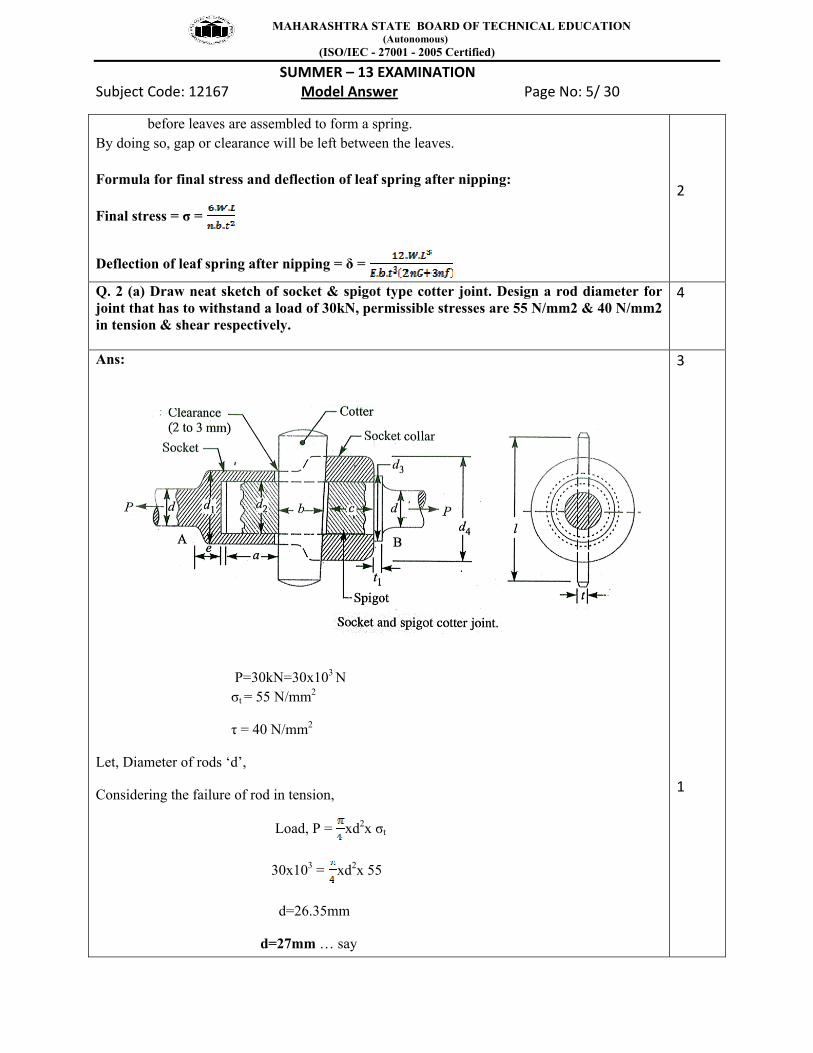
Q. 2 (a) Draw neat sketch of socket & spigot type cotter joint. Design a rod diameter for joint that has to withstand a load of 30kN, permissible stresses are 55 N/mm2 & 40 N/mm2 in tension & shear respectively.
4
Ans:
P=30kN=30x103 N σt = 55 N/mm2
τ = 40 N/mm2
Let, Diameter of rods ‘d’,
Considering the failure of rod in tension,
Load, P = xd2x σt
30x103 = xd2x 55
d=26.35mm
d=27mm … say
3
1

MAHARASHTRA STATE BOARD OF TECHNICAL EDUCATION (Autonomous)
(ISO/IEC - 27001 - 2005 Certified)
SUMMER – 13 EXAMINATION Subject Code: 12167 Model Answer Page No: 6/ 30
Q.2. (b) Draw neat sketch showing Through bolt, Tap bolt & stud. Write how screw threads are designated.
4
Sketch of Through bolt:
Sketch of Tap bolt:
Sketch of Stud:
Designation of Screw threads: According to Indian standards, IS:4218 (Part IV) 1976, (Reaffirmed 1990); the complete designation of screw thread shall include:
i) Size Designation: The size of the screw thread is designated by the letter ‘M’ followed
1
1
1
1

MAHARASHTRA STATE BOARD OF TECHNICAL EDUCATION (Autonomous)
(ISO/IEC - 27001 - 2005 Certified)
SUMMER – 13 EXAMINATION Subject Code: 12167 Model Answer Page No: 7/ 30
by the diameter and pitch, the two being separated by the sign ‘X’. When there is no indication of the pitch, it shall mean that a coarse is implied.
ii) Tolerance designation: This shall include a) A figure designating tolerance grade as indicated below, ‘7’ for fine grade, ‘8’ for
normal (medium) grade and ‘9’ for coarse grade. b) A letter designating the tolerance position as indicated below:
‘H’ for unit thread, ‘d’ for bolt thread with allowance, and ‘h’ for bolt thread without allowance.
For Example: M6-8d: A bolt thread of 6mm size of coarse pitch and with allowance on the threads and normal tolerance grade.
Q.2. (c) Design a knuckle joint to transmit a pull of 150kN. The ultimate strength of material used is 300MPa in tension, 240MPa in shear and 600 MPa in crushing. Take factor of safety = 4.
4
Ans: Given Data: P=150kN=150x103 N σtu = 300MPa=300 N/mm2
τu = 240 MPa=240 N/mm2
σcu = 600MPa=600 N/mm2
Factor of Safety = 4
We know that, permissible tensile stress for rod material,
σt = = = 75 N/mm2
τ = = = 60 N/mm2
σc= = = 150 N/mm2
1) Failure of solid rod in tension:
d = Diameter of rod,
P = xd2x σt
150x103 = xd2x 75
d= 50.4 mm
d=52mm
1

MAHARASHTRA STATE BOARD OF TECHNICAL EDUCATION (Autonomous)
(ISO/IEC - 27001 - 2005 Certified)
SUMMER – 13 EXAMINATION Subject Code: 12167 Model Answer Page No: 8/ 30
Now various dimensions are fixed as follows:
i) Diameter of knuckle pin, d1 = d= 52mm
ii) outer diameter of eye, d2 = 2d = 2x52=104mm
iii) Diameter of knuckle pin head and collar, d3 = 1.5d=1.5x52 = 78mm
iv) Thickness of single eye or rod end, t = 1.25d = 1.25x52 = 65mm
v) Thickness of fork, t1 = 0.75d= 0.75x52 = 39mm ~ 40mm
vi) Thickness of pin head, t2 = 0.5d = 0.5x52 = 26mm
2) Failure of knuckle pin in shear:
Since the knuckle pin is in double shear,
Load, P =2x x (d1)2x τ
150x103 =2x x (52)2x τ τ = 35.3 N/mm2
Note: Check with any one of the following Failure method .for single and Double eye
1)Failure of Single eye or rod end in tension:
The Single eye or rod end may fail in tension due to the load,
Load, P = (d2-d1) x t x σt
150x103 = (104-52) x 65 x σt
σt = 44.4 N/mm2
2)Failure of Single eye or rod end in Shearing:
The Single eye or rod end may fail in shear due to the load,
Load, P = (d2-d1) x t x τ
150x103 = (104-52) x 65 x τ
τ = 44.4 N/mm2
3) Failure of Single eye or rod end in crushing:
The Single eye or rod end may fail in crushing due to the load,
Load, P = d1 x t x σc
1
1

MAHARASHTRA STATE BOARD OF TECHNICAL EDUCATION (Autonomous)
(ISO/IEC - 27001 - 2005 Certified)
SUMMER – 13 EXAMINATION Subject Code: 12167 Model Answer Page No: 9/ 30
150x103 = 52 x 65 x σc
σc = 44.4 N/mm2
1)Failure of double eye or forked end in tension:
The double eye or forked end may fail in tension due to the load,
Load, P = (d2-d1) x 2 x t1 x σt
150x103 = (104-52) x 2 x 40 x σt
σt = 36 N/mm2
2)Failure of double eye or forked end in Shear:
The double eye or forked end may fail in Shear due to the load,
Load, P = (d2-d1) x 2 x t1 x τ
150x103 = (104-52) x 2 x 40 x τ
τ = 36 N/mm2
3)Failure of double eye or forked end in Crushing:
The double eye or forked end may fail in Crushing due to the load,
Load, P = d1 x 2 x t1 x σc
150x103 = 52 x 2 x 40 x σc
σc = 36 N/mm2
From above, we see that, the induced stresses are less than the given design stresses,
therefore the joint is safe.
1
Q.2. (d) A single plate with both sides effective, has outer and inner diameter 300 mm and 200 mm respectively. the maximum intensity of pressure at any point of contact is not to exceed 0.2 N/mm2. If the coefficient of friction is 0.3. Determine the power transmitted by clutch at shaft speed 2500 rpm.
4
Ans: Given data:
Outer diameter = d1 = 300 mm or r1 = d1 /2= 300/2 = 150mm
Inner diameter = d2 = 200 mm or r2 = d2 /2= 200/2 = 100mm

MAHARASHTRA STATE BOARD OF TECHNICAL EDUCATION (Autonomous)
(ISO/IEC - 27001 - 2005 Certified)
SUMMER – 13 EXAMINATION Subject Code: 12167 Model Answer Page No: 10/ 30
Maximum intensity of pressure = Pmax. = 0.1 N/mm2
Coefficient of Friction = 0.3
Shaft Speed = N = 2500 rpm
Since, the intensity of pressure is maximum at inner radius, therefore, for uniform wear,
Pmax. x r2 = C
C = 0.1 x 100
C = 10 N/mm
We know that, axial thrust,
W = 2πC (r1 – r2)
= 2 x π x 10 x (150-100)
W = 3141.5 N
and mean radius of friction,
r = (r1 + r2 )/2
= (150+100)/2
r = 125 mm.
We know that, torque transmitted,
T = η.µ.W.r
= 2 x 0.3 x 3141.5 x 125
= 235612.5 N-mm
T = 235.6 Nm
Power transmitted by clutch,
1
1
1
1

MAHARASHTRA STATE BOARD OF TECHNICAL EDUCATION (Autonomous)
(ISO/IEC - 27001 - 2005 Certified)
SUMMER – 13 EXAMINATION Subject Code: 12167 Model Answer Page No: 11/ 30
Q.2. (e) Define stress concentration. Explain its causes and suggest with proper sketches for following: i) Stepped shaft ii) Cylindrical member with threads
4
Ans: Stress Concentration: Whenever a machine component changes the shape of its cross section, the simple stress distribution no longer holds good and neighborhood of the discontinuity is different. This irregularity in the stress distribution caused by abrupt changes of form is called stress concentration.
OR Whenever there is a change in cross section of machine components, it causes high localized stresses. This effect is called as stress concentration. Causes of stress concentration and their remedies:
i) Stepped Shaft: Causes: Abrupt changes of shape and cross section. Concentrated loads applied at points or small areas of machine elements. Remedies: Avoid abrupt changes in cross section Provide fillet when change in cross section if necessary. Make gradual changes in cross section.
ii) Cylindrical members with threads Causes: Force flow line is bent as it passes from the shank portion to threaded portion of component due to changes in cross section. This results in stress concentration in transition plane. Remedies: Small under cut is taken between shank and the threaded portion of the component and a fillet radius is provided for this under cut. Shank diameter is reduced and made equal to the core diameter of the thread.
1
1.5
1.5

MAHARASHTRA STATE BOARD OF TECHNICAL EDUCATION (Autonomous)
(ISO/IEC - 27001 - 2005 Certified)
SUMMER – 13 EXAMINATION Subject Code: 12167 Model Answer Page No: 12/ 30
Q3a) list and draw sketches of any four types of keys and write their applications 04
Ans: Types of keys 1. Sunk Keys 2. Saddle Keys 3. Tangent Keys 4. Round Keys 5. Splines
Use: Key is used to connect shaft and hub of pulley or coupling.
Saddle key-for low load
Sunk key – for medium load
Splines – heavy load.
(ANY 4 FIGURES, ONLY KEY CAN ALSO BE CONSIDERED)
1
1
2
Q3b) Define lever. Describe three basic types of levers 04
Ans:
Definition: A lever is a rigid rod or a bar capable of turning about a fixed point called fulcrum.
In lever load ‘W ‘and Effort ‘P’ can be applied in three different ways depending on that levers are called First Type, Second Type and Third Type.
In first type Fulcrum is in between load and effort. Eg handle of pump, hand wheel punching press, beam of balance, foot lever etc
In second type the load is in between the fulcrum and effort. Eg. Levers of loaded safety valve
1

MAHARASHTRA STATE BOARD OF TECHNICAL EDUCATION (Autonomous)
(ISO/IEC - 27001 - 2005 Certified)
SUMMER – 13 EXAMINATION Subject Code: 12167 Model Answer Page No: 13/ 30
In third type the effort is in between fulcrum and load. Such levers are not recommended in engineering practice due to mechanical advantage less than one.
2
1
Q3c ) Compare foot lever and hand lever on basis of i) effort required to operate ii) Application iii) cross section used iv) Material
04
Ans:
Sr.
No
Basis Hand lever Foot lever
1 effort required to operate About 400 N About 800 N
2 Application Hand pump (or similar) Brake pedal ( or similar)
3 cross section used Retangular:
Thickness is constant but taper in width
Retangular:
Thickness is constant but taper in width
4 Material Wrought iron or mild steel
Wrought iron or mild steel
1
1
1
1
Q3d) A helical spring is made from a wire of 6mm diameter and has a outside diameter of 75mm. if the permissible shear stress is 350Mpa and modulus of rigidity 84 KN/mm2. Find the axial load which the spring can carry and the deflection per active turn neglecting the effect of curvature. Take shear stress factor Ks = 1 + 1/2c.
04
Ans: Given: d=6mm, Do=75mm, τ=350Mpa, G= 84Kn/mm2 = 84 x 103 N/mm2.
Outside diameter of spring D = Do – d = 75-6 = 69mm.
Therefore Spring Index C=D/d = 69/6 = 11.5
Let W = Axial load and
δ/n = Deflection per active turn.
1

MAHARASHTRA STATE BOARD OF TECHNICAL EDUCATION (Autonomous)
(ISO/IEC - 27001 - 2005 Certified)
SUMMER – 13 EXAMINATION Subject Code: 12167 Model Answer Page No: 14/ 30
Neglecting the effect of curvature
Ks= 1+ 1/2C = 1.
And maximum shear stress induced in wire (τ)
τ = Ks x 8 W.D/ πd3
Therefore W= 412.7 N
Deflection of spring δ = 8W.D3.n / G.d4
Therefore deflection per active turn
δ/n = 8W.D3 / G.d4
= 9.96 mm.
1
1
1
Q3e) Compare clutch with gear box 04
Ans:
Clutch Gear box
1)Clutch is a device used in automobile to engage or disengage the engine to transmission system
1)Gear box is used to provide different torque ratios at varied speed and road requirement
2)It transmits the same torque 2)It increases or decreases the torque produced by the engine
3)The clutch is located between engine and gear box.
3)It is located between clutch and propeller shaft
4) The clutch is disengaged while shifting gears.
4)Gear is changed to obtain required torque.
4
Q 4 . a) Determine the smallest size of the punch that can be made to punch 10 mm thick m.s. plate having ultimate shear stress as 0.3 kN/mm2 and permissible crushing stress for hardened punch is 1.3 kN/mm2.
04
Ans: Given: σ p =1.3 KN/mm2, τ ult. m =0.3 KN/mm2, thickness of plate t=10mm
Let‘d ’= smallest size of hole that can be punched
For punching the hole.
Permissible crushing strength of punch ≥ ultimate shear strength of material

MAHARASHTRA STATE BOARD OF TECHNICAL EDUCATION (Autonomous)
(ISO/IEC - 27001 - 2005 Certified)
SUMMER – 13 EXAMINATION Subject Code: 12167 Model Answer Page No: 15/ 30
Π/4 .d2. σ p ≥ Π d t. τ ult
Putting values we get d ≥ 9.2 mm
Therefore smallest size of hole that can be punched = 9.2 mm.
2
1
1
Q4.b) With neat sketch of socket and spigot cotter joint, write procedure to design cotter only.
04
Ans:
In Fig:
P = load carried by the rods
d = Diameter of the rods
d1 = outside diameter of socket
d2= Daimeter of Spigot or inside diameter of socket
d3= outside diameter of spigot collar
t1= thickness of spigot collar
d4 = diameter of socket collar
c = thickness of socket collar
b = mean width of cotter
t = thickness of cotter
l = length of cotter
02

MAHARASHTRA STATE BOARD OF TECHNICAL EDUCATION (Autonomous)
(ISO/IEC - 27001 - 2005 Certified)
SUMMER – 13 EXAMINATION Subject Code: 12167 Model Answer Page No: 16/ 30
a = distance from end of the slot to the end of rod
Failure of cotter in shear:
Since cotter fails in double shear
Therefore shearing area of cotter = 2 b x t
And shearing strength of cotter = 2b x t x τ
Equating this to load ‘P’ we get P = 2b x t x τ
from this width of cotter is determined.
2
Q 4. c) State material and application of turn buckle. Design only rod diameter for a turnbuckle to withstand a load of 50kN. The permissible stresses in rod material are 75 N/mm2 and 60 N/mm2 in tension and shear respectively.
4
Ans: Material for turn buckle: The tie rod and coupler may be of same material. Generally it is made up of steel or Cast iron.
Applications: it is used in aeroplanes, tie bar of jib crane, to connect compartment of locomotives, tie string of electric poles.
Example:
Given P=50 KN, σ t =75 N/mm2, τ =60 N/mm2
1. Design load Pd = 1.3 P = 1.3 x 50 = 65 N
2. Let Core diameter of rod = dc Now, Pd = Π/4 . dc 2. σ t
dc = 33.2 mm
3. Rod diameter d = dc/0.84 = 39.5 mm ≈ 40mm
1
1
1
1
d) How are the solid shafts subjected to combined twisting moment and bending moment designed?
04

MAHARASHTRA STATE BOARD OF TECHNICAL EDUCATION (Autonomous)
(ISO/IEC - 27001 - 2005 Certified)
SUMMER – 13 EXAMINATION Subject Code: 12167 Model Answer Page No: 17/ 30
If shaft is subjected to twisting moment ‘T’ and bending moment ‘M’
Then equivalent twisting moment ‘Te’ is calculated by using formula
also equivalent bending moment is calculated by using formula ]
and shaft diameter is calculated by using equation
= Π /16 τ d3
and ] = Π /32 σ b d3
Where τ = allowable shear stress in shaft material
σ b = allowable bending stress in shaft material
The maximum value of above two is considered.
1
1
1
1
Q4 B) a) The rear axle shaft connecting differential to side wheel is required to transmit 30 kW at 1500 rpm. If maximum torque is two times average torque and allowable shear stress is 80 N/mm2 for axle shaft material, find out diameter of axle shaft if
i)shaft is solid
ii) shaft is hollow with outside diameter 1.5 times inside diameter.
06
Given: P= 30 KW = 30 x 103 W, n=1500 rpm, τ =80 N/mm2
1. Let average torque transmitted by rear axle shaft = ‘T’ We know that, P = 2 Π nT/60
Therefore, T= 190.98 N-m = 190.98 x 10³ N-mm
Now maximum torque Tmax = T X 2 = 190.98 x 103 X 2 = 381.97 x 10³ N-mm
Case I: if shaft is solid
Let d = diameter of shaft,
We know that Tmax = Π /16 τ d3
d = 28.97 ≈ 29mm
Case II: If shaft is hollow
Let di= inner diameter of shaft, and do = outer diameter of shaft
K= di/do = 1/1.5 ---- given
1
1
2

MAHARASHTRA STATE BOARD OF TECHNICAL EDUCATION (Autonomous)
(ISO/IEC - 27001 - 2005 Certified)
SUMMER – 13 EXAMINATION Subject Code: 12167 Model Answer Page No: 18/ 30
We know that Tmax = Π /16 τ do3 (1 – k4)
Putting values we get do3 = 30302.68
Do = 31.176mm ≈ 32mm, and di = 21.33 ≈ 21 mm
2
Q4 B) b) With simple sketch explain procedure to design rocker arm for exhaust valve. 06
a. Figure shows the rocker arm for operating the exhaust valve. In designing rocker arm following steps are followed 1. Rocker arm is usually I-Section it is subjected to bending moment. To find
bending moment it is assumed that the arm of the lever extends from point of application of load to centre of pivot.
2. The ratio of length to the diameter of the fulcrum pin and roller pin is taken as 1.25. the permissible bearing pressure on this pin is taken from 3.5 to 6 N/mm2.
3. The outside diameter of boss at fulcrum is usually taken twice the diameter of the pin at fulcrum. The boss is provided with a 3mm thick phosphor bronze bush to take up the wear.
4. One end of rocker arm has a forked end to receive roller. 5. The outside diameter of the eye at the forked end is also taken as twice the
diameter of pin. The diameter of roller is slightly larger (at least 3mm more) than the diameter of eye at the forked end. The radial thickness of each eye of the forked end is taken half the diameter of pin. Some clearance about 1.5mm must be provided between the roller and the eye at the forked end so that roller can move
3
3

MAHARASHTRA STATE BOARD OF TECHNICAL EDUCATION (Autonomous)
(ISO/IEC - 27001 - 2005 Certified)
SUMMER – 13 EXAMINATION Subject Code: 12167 Model Answer Page No: 19/ 30
freely. The pin should, therefore be checked for bending. 6. The other end of rocker arm (i.e. tappet end) is made circular to receive the tappet
which is a stud with a lock nut. The outside diameter of the circular arm is taken as twice the diameter of the stud. The depth of section is also taken twice the diameter of stud.
Q-5 .a) Design and make a neat sketch of a rigid coupling for a shaft which transmits 250 N-m between two co-axial shafts. The shaft is made up of alloy steel. Flanges out of cast iron and bolts out of steel. Four bolts are used to couple flanges. The shafts are keyed to flange hub. The permissible stresses are given below:
Shear stress for shaft = 100 MPa, Crushing stress on shaft =200 MPa,
Shear stress on key = 100 MPa, Bearing stress on key =250 MPa,
Shear stress on cast iron = 200 MPa, Shear stress on bolt = 100 MPa.
8
Ans- Given: T=250 N-m = 250 x 103 N-mm ; n = 4 ; τs=100 MPa = 100 N/ mm2;
σcs=200 MPa =200 N/ mm2; τk =100 MPa= 100 N/ mm2; σck=250 MPa =250 N/ mm2;
τc=200 MPa = 200 N/ mm2; τb=100 MPa = 100 N/ mm2;
1. Design for hub First of all,let us find the diameter of the shaft (d). Torques transmitted by the shaft(T),
333s
3 d64.19d10016
d16
10x250 =××π
=×τ×π
=
35.23ord1272964.19/10250d 33 ==×=∴ say 25 mm
Outer diameter of the hub, D= 2d =2 x 25 = 50 mm
Length of the hub, L=1.5 d=1.5 x 25 = 37.5 mm
Check induced shear stress in the hub by considering it as a hollow shaft.
⎟⎟⎠
⎞⎜⎜⎝
⎛ −×τ×
π=⎟⎟
⎠
⎞⎜⎜⎝
⎛ −τ×
π=
502550
16DdD
1610x250
44
c
44
c3
τc=10.86 N/ mm2 =10.86 MPa
Since the induced shear stress for the hub material ( i.e. cast iron ) is less than 200 MPa,
therefore the design for hub is safe.
2. Design for key
2

MAHARASHTRA STATE BOARD OF TECHNICAL EDUCATION (Autonomous)
(ISO/IEC - 27001 - 2005 Certified)
SUMMER – 13 EXAMINATION Subject Code: 12167 Model Answer Page No: 20/ 30
Find that proportions of key for a 25 mm diameter shaft are:
Width of key w = 10 mm
Thickness of key t = 8 mm
The length of key (l) is taken equal to the length of hub,
l = L =37.5
Let us now check the induced shear and crushing stresses in the key .
Considering key in sharing
T = l x w x τk x 2d
250 x 103 = 37.5 x10 x τk x 225
τk = 53.3 N/ mm2 =53.3 MPa
Considering the key in crushing
T = l x 2t
x σck x 2d
250 x 103 = 37.5 x28
x σck x 225
σck = 133.3 N/ mm2 =133.3 MPa
Since the induced share and crushing stresses in the key are less than the given stresses. Therefore the design of the key is safe.
3 Design for flange
The thickness of the flange (tf) is taken at 0.5 d
tf = 0.5 d = 0.5 x 25 = 12.5
Now let us check the induced share stress in the flange by considering the flange at the junction of the hub in share.
Torque transmitted T =fc
2
t2D
×τ×π
2

MAHARASHTRA STATE BOARD OF TECHNICAL EDUCATION (Autonomous)
(ISO/IEC - 27001 - 2005 Certified)
SUMMER – 13 EXAMINATION Subject Code: 12167 Model Answer Page No: 21/ 30
250 x 103= 5.12250
c
2
×τ×π
cτ = 5.1 N/mm2
Since the induced share stress in the flange of cast iron is less than 200 MPa, therefore design of flange is safe.
4 Design for bolts
Let d1= Nominal diameter of the bolts
D1 = pitch circle diameter of bolts = 3d = 3 x 25 = 75
The bolts are subjected to share stress due to the torque transmitted.
We know that torque transmitted T
250 x 103=2
Dn4d 1
b
21 ××τ×
π =2
7541004d 2
1 ×××π
= 4.6 mm
Assuming coarse threads .the nearest standard size of the bolt is M 6
Outer diameter of the flange
D2= 4 d= 4 x 25 = 100 mm
Thickness of the protective circumferential flange ,
tp = 0.25 d = 0.25 x 25 = 6.25 mm
2
2
Q-5 .b) An automotive gear box gives three forward and a reverse speed with top gear of unity and bottom and reverse gear ratio’s of 3.3:1, the centre distance between shafts is 110 mm approximately. Gear teeth of module 3.25 mm are to be employed. Sketch simple layout of constant mesh gear box for these conditions giving the number of teeth for various gear wheels and showing own closely the different gear ratios are obtained
8
Ans- Given data- Module=3.25 mm
centre distance between shafts =110 mm
Since the pitch is same for all wheels and the centre distance same for all the pairs meeting the wheels, the total no. of teeth must be same for each pair

MAHARASHTRA STATE BOARD OF TECHNICAL EDUCATION (Autonomous)
(ISO/IEC - 27001 - 2005 Certified)
SUMMER – 13 EXAMINATION Subject Code: 12167 Model Answer Page No: 22/ 30
There fore TA + TB= TC+ TD= TE+ TF = T
T = ( 2 * C.D.) / M
T = ( 2 *110) / 3.25=67.8
T=68 teeth
In general practice for better results gear ratios are kept in geometric progression if G1,G2,G3 are gear ratios in first, second and third gear ,then
3
2
2
1
GG
GG
=
G2 = 21 GG ×
= 3.31×
= 1.817
In general practice,while designing a gear box it is desired that the gear ratio should be minimum possible in all cases, so that the sizes of the gear box can be kept minimum.
To achieve this, the maximum reduction required in gear box ( in first gear) is achieved in two equal steps.
Now G1 =C
D
A
B
TT
TT
×
Let X be the reduction in one step
therefore G1 = XX ×
3.3 = X2
X = 1.817
C
D
A
B
TT
TT
= = 1.817
TB = 1.817 TA and TD = 1.817 TC
TA + TB= 68 , TA + 1.817 TA=68 , TA= 68/2.817
TA=24 teeth
1

MAHARASHTRA STATE BOARD OF TECHNICAL EDUCATION (Autonomous)
(ISO/IEC - 27001 - 2005 Certified)
SUMMER – 13 EXAMINATION Subject Code: 12167 Model Answer Page No: 23/ 30
TB= 68-24 TB=44 teeth
Similarly TC=24 teeth and TD=44 teeth
Actual gear ratio G1 =C
D
A
B
TT
TT
×
G1=2444
2444
×
G1=3.36:1
Second gear ratio G2 =E
F
A
B
TT
TT
×
1.817=E
F
TT
×2444
TF=0.991 TE
TE+ TF = 68
TE+ 0.991 TE =68
TE =34 teeth
TF=68 - 34 = 34 teeth
Actual gear ratio in second gear = G2 =3434
2444
× =1.833
Top gear ratio G3 =1:1 is obtained by directly coupling the main shaft to engine shaft. Now reverse gear and idler is fitted due to presence of which the direction is reversed also it is required that TD + TI < 68 to avoid interference of gear C and D
Therefore Ti < 68 - TD
Ti < 68 - 44
Ti < 22
Exact gear ratio GR =I
D
A
B
TT
TT
× GR =2044
2444
×
GR =4.03:1
3
1

MAHARASHTRA STATE BOARD OF TECHNICAL EDUCATION (Autonomous)
(ISO/IEC - 27001 - 2005 Certified)
SUMMER – 13 EXAMINATION Subject Code: 12167 Model Answer Page No: 24/ 30
Exact centre distance between shaft,
C.D.2
)TB +TA (M=
= 2
)68(25.3
= 110.5 mm
Constant mesh gear box
1
2
Q-5 .c) Determine the thickness of plain cylinder head for 0.3 m cylinder diameter. The maximum gas pressure is 3.2 N/mm2 .Design the studs and cylinder cover. Take allowable tensile stress for cylinder cover and bolt equal to 42 N/mm2 and 63 N/mm2 respectively.
8
Ans-Given Data:D = 0.3 m =300 mm p = Maximum pressure =3.2 N/mm2, σc for cover =42 N/ mm2, σt for bolts =63 N/ mm2
th- thickness of the cylinder head
D = Cylinder bore in mm
p = Maximum pressure inside the cylinder in N/mm2,
σc = Allowable circumferential stress for cover in MPa or N/mm2
C = Constant whose value is taken as 0.1.

MAHARASHTRA STATE BOARD OF TECHNICAL EDUCATION (Autonomous)
(ISO/IEC - 27001 - 2005 Certified)
SUMMER – 13 EXAMINATION Subject Code: 12167 Model Answer Page No: 25/ 30
th= 26.2=26.5 mm
The pitch circle diameter (Dp) is usually taken as D + 3d.
d = Nominal diameter of the stud in mm,
dc = Core diameter of the stud in mm. It is usually taken as 0.84 d.
σt = Tensile stress for the material of the stud which is usually nickel steel.
nb = Number of Bolts. It may be taken as 0.01 D + 4 to 0.02 D + 4=7 to 10
The load on bolts =
2*3.2
This load resisting by ns No. of Bolts
2*3.2= nb σt for bolts
dc = Core diameter of the bolts in mm. It is usually taken as 0.84 d.
Lets take nb=8
2*3.2= nb σt
d=40 mm
Now circular Pitch of Bolts =164.93 mm
Now minimum pitch should be 3d = 120 mm
Maximum pitch lies between 19 d to 28.5 d
=19 40 to 28.5 40
= 120.162 to 180.24
Pitch circle of bolts = 164.93 mm is lies between 19 d to 28.5 d
Hence design is safe.
2
1
3
2

MAHARASHTRA STATE BOARD OF TECHNICAL EDUCATION (Autonomous)
(ISO/IEC - 27001 - 2005 Certified)
SUMMER – 13 EXAMINATION Subject Code: 12167 Model Answer Page No: 26/ 30
Q 6.a) State and justify material used for piston. Draw a neat sketch showing allowance for piston expansion. Design crown thickness for following data,
Maximum pressure inside the cylinder = 4.5N/mm2
Piston diameter = 70 mm, Stroke length =80 mm, Allowing bending stress = 45 N/mm2
8
Ans:
Materials used for pistons of I.C. engines are cast iron, cast aluminum, forged aluminum, cast steel and forged steel. The cast iron pistons are used for moderately rated engines with piston speeds below 6 m /s and aluminum alloy pistons are used for highly rated en gines running at higher piston speeds.
Piston Clearance Diagram
Given Data - D = 8 mm,P = 4.5 N/mm2 , σb = 45 N/mm2
Let the thickness of piston head can be designed by assuming the head to be a flat plate uniform thickness and fixed at the edges and assuming the gas load to be uniform distributed
th = b
PDσ16
3 2
where th = thickness of piston crown
P = Pmax
3
2

MAHARASHTRA STATE BOARD OF TECHNICAL EDUCATION (Autonomous)
(ISO/IEC - 27001 - 2005 Certified)
SUMMER – 13 EXAMINATION Subject Code: 12167 Model Answer Page No: 27/ 30
th = 4516
805.43 2
×××
th = 10.95 mm
th = 11 mm
3
Q 6. b) Explain why I-section are used for connecting rod. What proportions of dimensions are
used.Design the connecting rod cross section for following data for petrol engine:
Maximum pressure inside the cylinder = 4.5N/mm2
Piston diameter = 70 mm, Stroke length =80 mm,
Effective length of connecting rod=140 mm
Ultimate crushing stress in rod material =300 N/mm2
Factor of safety =3 Take rankine constant for steel = 1/1600
8
Ans: I-sections are usually found to be most suitable for high speed engine connecting rod lightness is essential in order to keep inertia forces as small as possible .I-section also provides sufficient strength required to with stand momentary high gas pressure in the cylinder .Thus I-section fulfils most desirable conditions for connecting rod i.e. adequate strength and stiffness and minimum weight
The most suitable section for the connecting rod is I-section with the proportions as shown in Fig.
Let thickness of the flange and web of the section = t
Width of the section, B = 4 t
2

MAHARASHTRA STATE BOARD OF TECHNICAL EDUCATION (Autonomous)
(ISO/IEC - 27001 - 2005 Certified)
SUMMER – 13 EXAMINATION Subject Code: 12167 Model Answer Page No: 28/ 30
and depth or height of the section, H = 5t
From Fig. find that area of the section,
A = 2 (4 t × t) + 3 t × t = 11 t2
Given Data- Pmax =4.5 N/mm2 , D =70 mm,l=80 mm,L= 180 mm, σcu = 330 N/ mm2,
σc =sf
cu
.σ =
3300
= 100 N/ mm2,
A = 11 t2 where t = thickness of rod
a = rankine contant = 1/ 1600
K = 218.3 t
w = maximum gas load= Pmax x .704
5.44
22 ππ×=D
w = 17.32 x 10³ N
Assuming I-section
w = ][1 2
2
xx
c
kLa
A
+
×σ
17.32 x 10³ N =
]18.3
140[16001/ 1
11100
2
2
2
t
t
+
×
t = 4.08mm say t = 4.5 mm
Other dimensions of I-section at middle , small end and big end
a) at the middle or centre dimension
(i) depth or height of section
H= 5 t =5 x 4.5
H= 22.5 mm
(ii) width of cross section B
B= 4 t = 4 x 4.5 =18 mm
2
2
2

MAHARASHTRA STATE BOARD OF TECHNICAL EDUCATION (Autonomous)
(ISO/IEC - 27001 - 2005 Certified)
SUMMER – 13 EXAMINATION Subject Code: 12167 Model Answer Page No: 29/ 30
b)Dimension at small end
(i) depth or height of section
H1=0.82H=0.82x22.5=18.45mm
(ii) width of cross section B
B= B1=18mm
c)Dimension at big end
i )depth or height of section
H2=1.18H=26.55 mm
ii) width of cross section B
B2=B=18mm
Q 6. c) Draw a neat sketch of overhead valve mechanism .Mention the material used For various components of mechanism .Design the port dimensions to lift for exhaust valve with following data: Diameter of piston = 70 mm, Stroke length = 80 mm,Exhaust velocity of gasses is 120 m/s with 5000 rpm gases enters at 450
8
Ans Overhead valve mechanism
Material used in valves mechanisms
Cam : Case hardened steel
Cam shaft : Mild steel
2

MAHARASHTRA STATE BOARD OF TECHNICAL EDUCATION (Autonomous)
(ISO/IEC - 27001 - 2005 Certified)
SUMMER – 13 EXAMINATION Subject Code: 12167 Model Answer Page No: 30/ 30
Rocker arm : mild steel
Spring : Manganese steel
Valve seal : Alloy steel.
Tappet: Alloy steel
Inlet Valves : Alloy steel or nickel chromium steel
Exhaust valves : Austentic type chromium steel
Given Data-D=70 mm L=80 mm
V1 = 120 m/s, α = 450, N = 5000 rpm =83.33 rev/sec
In one revolution ,piston travells a distance = 2 x stroke length
=2 x 80= 160 mm hence in one sec ,piston travells a distance = 83.33 x 160 mm/sec
==3.33 m/sec
Port Diameter pd
Now a1V1= A V a1 = Area of the port,V = Mean velocity of the piston.
33.3704
1204
22 ×=×ππ
pd
2pd = 544.30 ∴ pd = 23.33
Maximum lift of the valve L
L= pd /4cosα
L = Lift of the valve. The lift of the valve may be obtained by equating the area across the valve seat to the area of the port. For a conical valve,
where α = Angle at which the valve seat is tapered = 45°.
L = 23.33/4cos45°.
L= 8.2484 mm Valve stem diameter
The valve stem diameter (ds) is given by
ds= dp/8 + 5 mm = 7.911=8 mm
2
1
1
1
1

MAHARASHTRA STATE BOARD OF TECHNICAL EDUCATION (Autonomous)
(ISO/IEC - 27001 - 2005 Certified)
SUMMER – 13 EXAMINATION Subject Code: 12167 Model Answer Page No: 31/ 30