Embed Size (px)
Citation preview
-1- By Chang C.K.
원자력발전소 우선전력계통 지락보호 개선방안 Improvement of the Ground Fault Protection for the Preferred Power
Supply Line of Nuclear Power Plants
장 중 구 KEPCO International Nuclear Graduate School Home Page : www.kings.ac.kr E-mail : [email protected]
2016.08
-2- By Chang C.K.
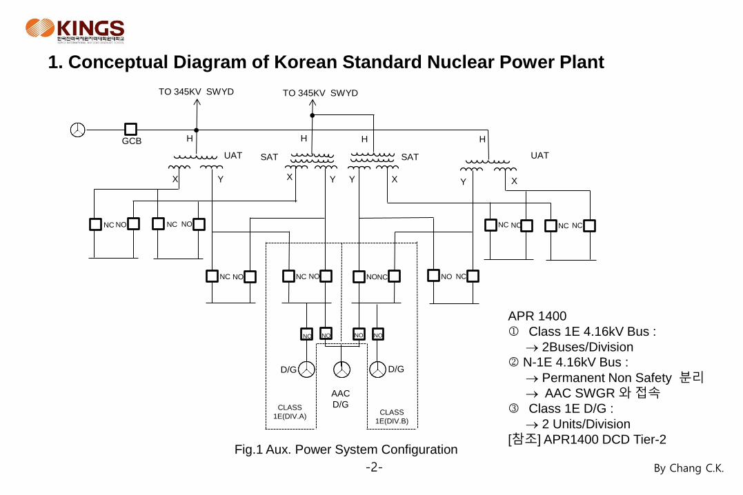
Fig.1 Aux. Power System Configuration
NC
TO 345KV SWYD
GCB
NC
X Y Y Y X X X Y
H H
SAT UAT
H
NC NC NC
NC
D/G D/G
AAC
D/G CLASS
1E(DIV.A) CLASS
1E(DIV.B)
NC NC NC
NC
TO 345KV SWYD
H
SAT UAT
NO NO
NO NO NO NO
NO NO NO NO
1. Conceptual Diagram of Korean Standard Nuclear Power Plant
APR 1400
Class 1E 4.16kV Bus :
2Buses/Division
N-1E 4.16kV Bus :
Permanent Non Safety 분리
AAC SWGR 와 접속
Class 1E D/G :
2 Units/Division
[참조] APR1400 DCD Tier-2
-3- By Chang C.K.
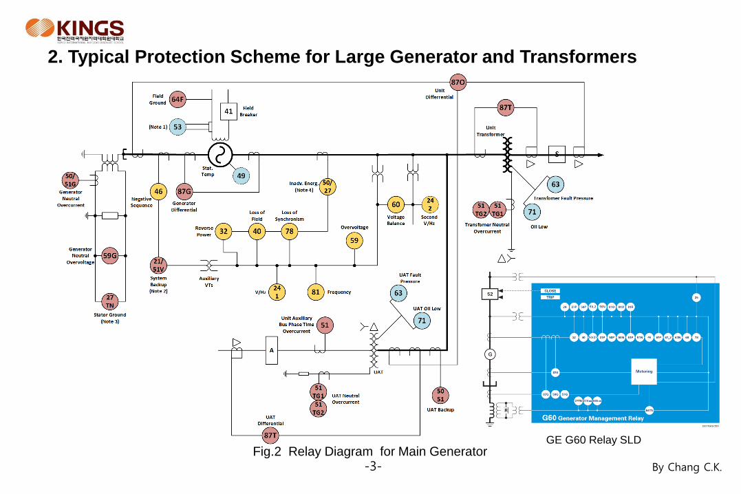
2. Typical Protection Scheme for Large Generator and Transformers
Fig.2 Relay Diagram for Main Generator GE G60 Relay SLD
-4- By Chang C.K.
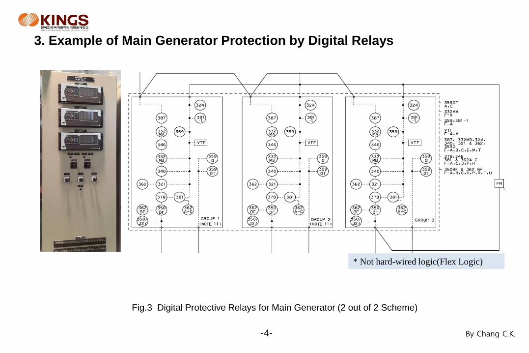
3. Example of Main Generator Protection by Digital Relays
Fig.3 Digital Protective Relays for Main Generator (2 out of 2 Scheme)
* Not hard-wired logic(Flex Logic)
-5- By Chang C.K.
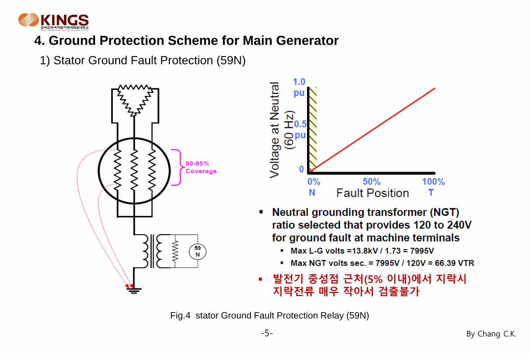
4. Ground Protection Scheme for Main Generator
1) Stator Ground Fault Protection (59N)
발전기 중성점 근처(5% 이내)에서 지락시 지락전류 매우 작아서 검출불가
Fig.4 stator Ground Fault Protection Relay (59N)
-6- By Chang C.K.
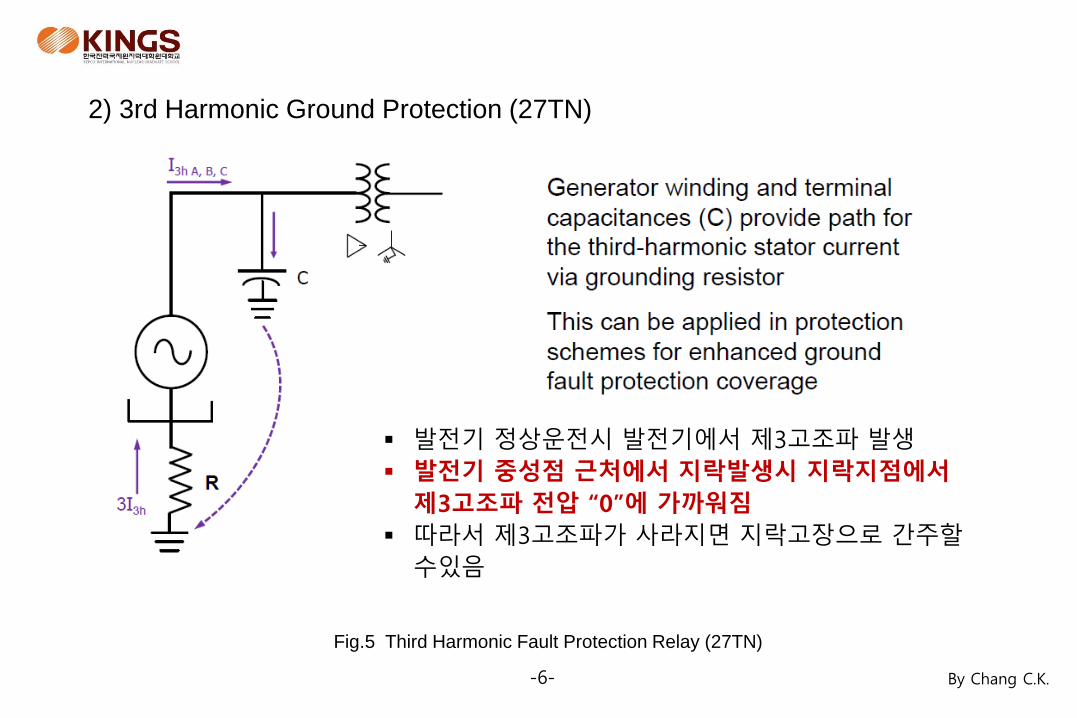
2) 3rd Harmonic Ground Protection (27TN)
발전기 정상운전시 발전기에서 제3고조파 발생
발전기 중성점 근처에서 지락발생시 지락지점에서
제3고조파 전압 “0”에 가까워짐
따라서 제3고조파가 사라지면 지락고장으로 간주할
수있음
Fig.5 Third Harmonic Fault Protection Relay (27TN)
-7- By Chang C.K.
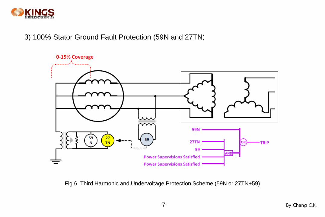
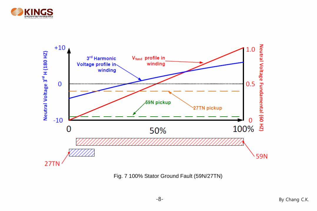
3) 100% Stator Ground Fault Protection (59N and 27TN)
Fig.6 Third Harmonic and Undervoltage Protection Scheme (59N or 27TN+59)
-8- By Chang C.K.
Fig. 7 100% Stator Ground Fault (59N/27TN)
-9- By Chang C.K.
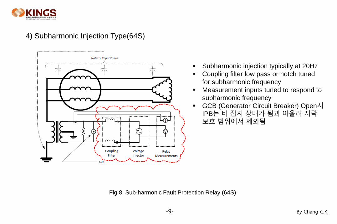
4) Subharmonic Injection Type(64S)
Fig.8 Sub-harmonic Fault Protection Relay (64S)
Subharmonic injection typically at 20Hz
Coupling filter low pass or notch tuned
for subharmonic frequency
Measurement inputs tuned to respond to
subharmonic frequency
GCB (Generator Circuit Breaker) Open시
IPB는 비 접지 상태가 됨과 아울러 지락보호 범위에서 제외됨
-10- By Chang C.K.
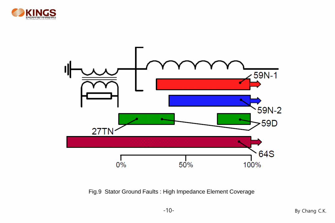
Fig.9 Stator Ground Faults : High Impedance Element Coverage
-11- By Chang C.K.
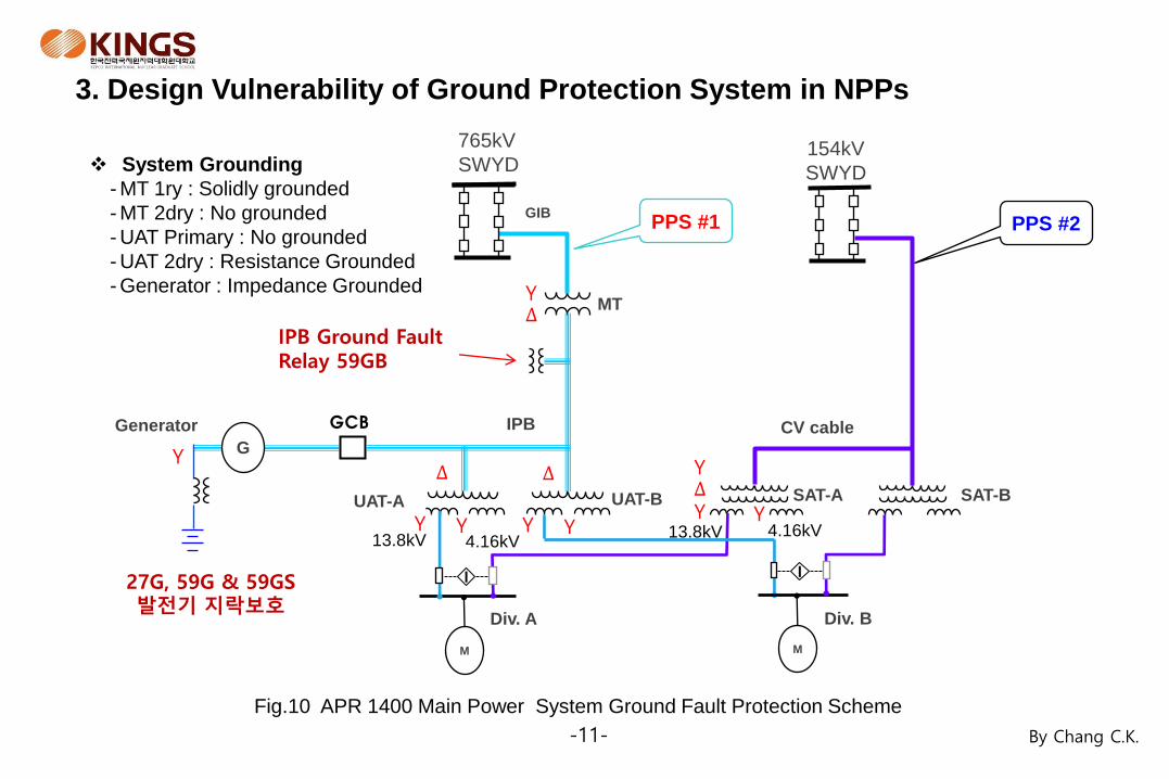
3. Design Vulnerability of Ground Protection System in NPPs
MT
Generator
SAT-A UAT-A
IPB
GIB
CV cable
765kV
SWYD 154kV
SWYD
UAT-B SAT-B
Div. A Div. B
PPS #1 PPS #2
G
M M
4.16kV 13.8kV 13.8kV 4.16kV
I I
Fig.10 APR 1400 Main Power System Ground Fault Protection Scheme
∆
∆ ∆
Y
Y Y Y Y
∆ Y
Y Y
Y
System Grounding
- MT 1ry : Solidly grounded
- MT 2dry : No grounded
- UAT Primary : No grounded
- UAT 2dry : Resistance Grounded
- Generator : Impedance Grounded
IPB Ground Fault Relay 59GB
27G, 59G & 59GS 발전기 지락보호
GCB
-12- By Chang C.K.
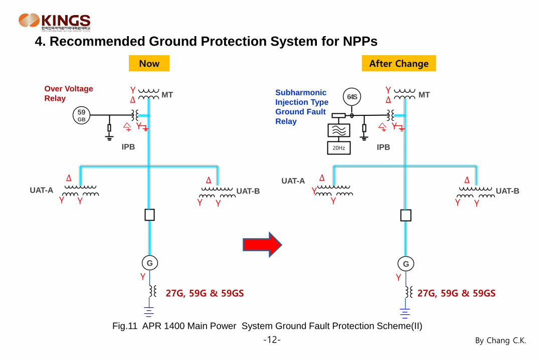
Fig.11 APR 1400 Main Power System Ground Fault Protection Scheme(II)
MT
UAT-A
IPB
UAT-B
G
∆
∆ ∆
Y
Y Y Y Y
Y
59 GB
Y
MT
UAT-A
IPB
UAT-B
G
∆
∆ ∆
Y
Y Y Y Y
Y
64S
Y
Now After Change
27G, 59G & 59GS
27G, 59G & 59GS
20Hz
Subharmonic
Injection Type
Ground Fault
Relay
Over Voltage
Relay
4. Recommended Ground Protection System for NPPs
-13- By Chang C.K.
5. Conclusions
59N : Stator Ground Overvoltage Relay (95%)
27TN : Third harmonic Ground Fault Protection (Supplementary for 59N)
59GB : Isolated Bus Ground Fault Protection
64S : Subharmonic Frequency Injection Type Ground Fault Relay(추가)
- Replace 59GB
- Improve the performance of ground fault detection when high impedance
ground fault is occurred.
- Install at the IPB instead of generator neutral. For the protection of the IPB
when the GCB is opened also.
[Note] The operating condition for the function is the ratio between the 20 Hz
auxiliary voltage and the current in the auxiliary current transformer, which is
interpreted to be the resistance value. In the event of an earth fault in the stator
winding, the resistance value decreases, and operates the function.