Embed Size (px)
Citation preview

1
Surgical Technique
Including

2
Nota Bene The technique description herein is made available to the healthcare professional to illustrate the authors’ suggested treatment for the uncomplicated procedure. In the final analysis, the preferred treatment is that which addresses the needs of the patient.
Surgical Technique for the TRIGEN™ Humeral Nail System using the TRIGEN SURESHOT™ Distal Targeting System
Table of contentsIntroduction ...................................................................................... 3TRIGEN Humeral Nail indications ....................................................... 4TRIGEN SURESHOT indications .......................................................... 5TRIGEN Humeral Nail design rationale .............................................. 6TRIGEN Humeral Nail specifications .................................................. 7Warnings and cautions for TRIGEN SURESHOT ............................... 8
Surgical ProcedureOR preparation ................................................................................... 9
Surgical TechniquePatient positioning ............................................................................. 11Instruments for opening the humerus ............................................... 12Incision ............................................................................................... 13Entry tool and guide pin placement ................................................... 14Instruments fracture reduction and reaming ..................................... 15Prepare proximal section ................................................................... 16Fracture reduction .............................................................................. 17Measuring implant length .................................................................. 18Additional limited reaming ................................................................. 18Instruments for nail assembly and insertion ..................................... 19Nail Drill Guide assembly .................................................................. 20Nail insertion ...................................................................................... 21Final version adjustment .................................................................... 22TRIGEN SURESHOT system set up ..................................................... 23IM Nail assembly drill guide .............................................................. 25Skin incision with TRIGEN SURESHOT ............................................... 26Targeting the locking hole .................................................................. 27Drilling the distal hole ........................................................................ 28Screw insertion .................................................................................. 29Instruments for proximal locking, distal locking and freehand distal locking of Proximal 16cm Humeral Nails .................................. 30Distal locking screws for TRIGEN Proximal 16cm Humeral Nails ....... 31Proximal locking screws ..................................................................... 32Distal locking screws without the use of TRIGEN SURESHOT ........... 35Closure ............................................................................................... 36
Catalog information ......................................................................... 37
3
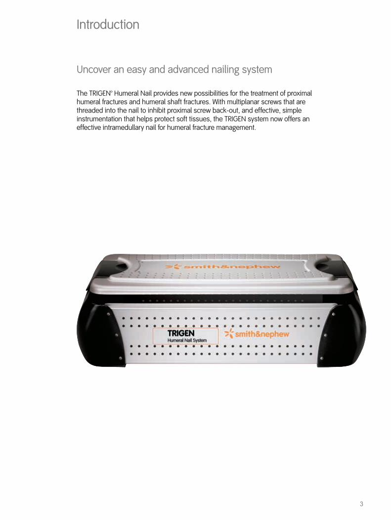
Uncover an easy and advanced nailing system
The TRIGEN™ Humeral Nail provides new possibilities for the treatment of proximal humeral fractures and humeral shaft fractures. With multiplanar screws that are threaded into the nail to inhibit proximal screw back-out, and effective, simple instrumentation that helps protect soft tissues, the TRIGEN system now offers an effective intramedullary nail for humeral fracture management.
Introduction

4
IntroductionTRIGEN™ Humeral Nail indications
Two-part fractures of the humerusThree-part fractures of the humerusMidshaft Diaphyseal Fracture(s)Segmental Humerus Fracture(s)
5
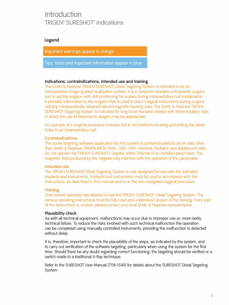
Important warnings appear in orange
Tips, tricks and important information appear in blue
Legend
Indications, contraindications, intended use and training The Smith & Nephew TRIGEN SURESHOT Distal Targeting System is intended to be an intraoperative image-guided localization system. It is a computer-assisted orthopaedic surgery tool to aid the surgeon with drill positioning for screws during intramedullary nail implantation. It provides information to the surgeon that is used to place surgical instruments during surgery utilizing intraoperatively obtained electromagnetic tracking data. The Smith & Nephew TRIGEN SURESHOT Targeting System is indicated for long bone fractures treated with intramedullary nails in which the use of stereotactic surgery may be appropriate.
An example of a surgical procedure includes but is not limited to locating and drilling the distal holes in an intramedullary nail.
Contraindications The screw targeting software application for this system is contraindicated for all IM nails other than Smith & Nephew TRIGEN META-NAIL™, TAN™, FAN, Humeral, Pediatric and Adolescent nails. Do not operate the TRIGEN SURESHOT Targeter within 200mm of an installed pacemaker. The magnetic field produced by the Targeter may interfere with the operation of the pacemaker.
Intended use The TRIGEN SURESHOT Distal Targeting System is only designed for use with the indicated implants and instruments. Implants and instruments must be used in accordance with the instructions, as described in this manual and/or in the non-navigated surgical procedure.
Training Only trained operators are allowed to use the TRIGEN SURESHOT Distal Targeting System. The various operating instructions must be fully read and understood as part of the training. If any part of the instructions is unclear, please contact your local Smith & Nephew representative.
Plausibility check As with all technical equipment, malfunctions may occur due to improper use or, more rarely, technical failure. To reduce the risks involved with such technical malfunction the operation can be completed using manually controlled instruments, providing the malfunction is detected without delay.
It is, therefore, important to check the plausibility of the steps, as indicated by the system, and to carry out verification of the software targeting, particularly when using the system for the first time. Should there be any doubt regarding correct functioning, the targeting should be verified or a switch made to a traditional X-Ray technique.
Refer to the SURESHOT User Manual (7118-1540) for details about the SURESHOT Distal Targeting System.
IntroductionTRIGEN™ SURESHOT™ indications

6
TRIGEN 8/7mm X 16cm
Proximal Straight Humeral Nail offers an alternate choice in treating different fracture patterns.
Straight Humeral Nail
5.0mm Cancellous Proximal Locking Screws; 24mm – 64mm lengths, 2mm increments
The TRIGEN Humeral Nailing System product offering includes a 16cm Proximal Straight Nail, a 16cm Proximal Bent Nail, and a full line of Long Bent Nails. Nails with a proximal bend are best suited for simple two-part fractures of the proximal humerus involving the surgical neck of the humerus and proximal third humeral fractures without comminution. In these scenarios, the proximal bend facilitates an easier entry portal attainment and nail insertion with an incision just medial to the rotator cuff insertion.
The Long Bent Humeral Nail is primarily indicated for humeral shaft fractures which are inherently not prone to varus malposition. The lateral portal design allows insertion just medial to the rotator cuff insertion and facilitates easier portal attainment and nail insertion.
The 16cm Proximal Straight Humeral Nail offers the option of a medialized entry site. If the greater tuberosity is fractured or compromised, a straight centralized starting point avoids fracture extension from the tuberosity fracture into the entry portal and resultant loss of nail stability. The entry portal for the straight nail is slightly more difficult to attain than the curved nail entry portal.
Proximal locking holes have innovative threaded design. Screws thread into the nail to help prevent screw back-out.
25° 25°
4.0mm Cortical Distal Locking Screws; 20mm – 40mm lengths, 2mm increments
Four multiplanar proximal locks improve fracture stability.
4 degree proximal bend
Long Bent Humeral Nail
Locking holes
IntroductionTRIGEN™ Humeral Nail design rationale

7
TRIGEN
Long Bent Humeral Nail 8/7mm, 9/7.5mm, 10/8.5mm Diameter; 18cm – 28cm lengths, by 2cm increments
TRIGEN
Humeral Nail 8/7mm x 16cm Proximal Bent Humeral Nail
TRIGEN
Humeral Nail 8/7mm x 16cm Proximal Straight Humeral Nail
Trapezoidal 12mm x 10.5mm cross section
Proximal Taper
First diameter measurement: 8mm,9mm, or 10mm
Second diameter measurement: 7mm, 7.5mm, or 8.5mm
Proximal Taper
Trapezoidal 12mm x 10.5mm cross section
Proximal taper
First diameter measurement: 8mm
Second diameter Measurement: 7mm
35mm
30mm
20mm
20mm
10mm
80mm
IntroductionTRIGEN™ Humeral Nail specifications

8
Warnings and cautions for TRIGEN™ SURESHOT™Refer to the SUR ESHOT Us er M anual ( 7118-1540) for a ll w arnings, c autions, m aintenance, c leaning and sterilization instructions.
Devices for system set up
Trauma Interface Cat. No. 7169-2802
Power CordCat. No. 6680-0193
TRIGEN™ SURESHOT™ TargeterCat. No. 7169-2801
Note The Targeter will be operated within the sterile field and may have contact with the skin of the patient. The drill sleeve inserts will be used in the incision and have direct bone contact.
Note Verify that the Targeter housing is not damaged (holes, tears, cracks). If the housing or the connector is damaged, the Targeter is no longer safe to use.
Note If the Targeter is not recognized after connection to the system, the Targeter is defective and must be exchanged. (See also instrument connection).
Note Broken or damaged instruments must be exchanged immediately and sent back to Smith & Nephew, Inc.
Note This device is provided non-sterile and must be cleaned and sterilized per Cleaning and Sterilization (Smith & Nephew document 7138-1339) prior to use.
WARNING: The maximum temperature of the Targeter body can reach 47° Celsius at ambient room temperatures above 30° C. The Targeter body should not remain in constant contact with a patient’s exposed skin for more than one minute.
9
Surgical procedure – OR preparation
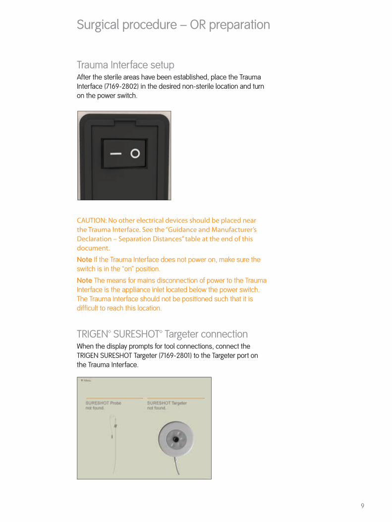
Trauma Interface setupAfter the sterile areas have been established, place the Trauma Interface (7169-2802) in the desired non-sterile location and turn on the power switch.
CAUTION: No other electrical devices should be placed near the Trauma Interface. See the “Guidance and Manufacturer’s Declaration – Separation Distances” table at the end of this document.
Note If the Trauma Interface does not power on, make sure the switch is in the “on” position.
Note The means for mains disconnection of power to the Trauma Interface is the appliance inlet located below the power switch. The Trauma Interface should not be positioned such that it is difficult to reach this location.
TRIGEN™ SURESHOT™ Targeter connectionWhen the display prompts for tool connections, connect the TRIGEN SURESHOT Targeter (7169-2801) to the Targeter port on the Trauma Interface.

10
The SURESHOT™ Targeter will change color to orange upon successful connection to the Trauma Interface.
CAUTION: The Targeter body may have contact with the patient and must remain in the sterile field at all times. Only the cable and connector may be removed from the sterile field.
CAUTION: Connect the Targeter at least 10 minutes prior to targeting in order to ensure proper accuracy.
Note When oriented as shown, the connector should assemble easily. Do not force the connector into the port.
Note If the Targeter is properly connected to the system and the application remains in this screen for more than 30 seconds, the Targeter may have been damaged during cleaning/sterilization. In this case another Targeter has to be used.
Note It is possible at any time to disconnect and reconnect tools when the application is running. The display will show a screen reporting the missing instrument.
Surgical procedure – OR preparation
11
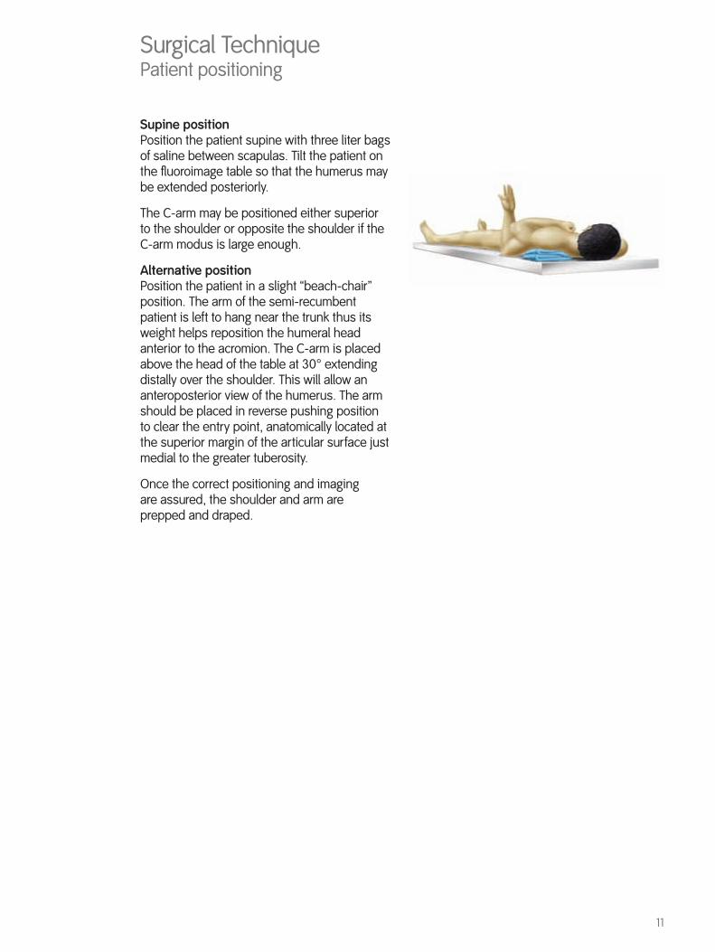
Supine positionPosition the patient supine with three liter bags of saline between scapulas. Tilt the patient on the fluoroimage table so that the humerus may be extended posteriorly.
The C-arm may be positioned either superior to the shoulder or opposite the shoulder if the C-arm modus is large enough.
Alternative positionPosition the patient in a slight “beach-chair” position. The arm of the semi-recumbent patient is left to hang near the trunk thus its weight helps reposition the humeral head anterior to the acromion. The C-arm is placed above the head of the table at 30° extending distally over the shoulder. This will allow an anteroposterior view of the humerus. The arm should be placed in reverse pushing position to clear the entry point, anatomically located at the superior margin of the articular surface just medial to the greater tuberosity.
Once the correct positioning and imaging are assured, the shoulder and arm are prepped and draped.
Surgical TechniquePatient positioning

12
Surgical TechniqueInstruments for opening the humerus
Entry Cuff Guard Cat. No. 7175-1100
3.2mm Tip Threaded Guide Pin Cat. No. 7175-1147
Trocar Cat. No. 7175-1136
Mini Connector with Handle Cat. No. 7175-1137
Straight Entry Reamer Cat. No. 7175-1103
Cannulated Awl Cat. No. 7175-1102
Straight Ratcheting Driver Cat. No. 7175-1141
Disposable Cuff Guard (Optional – may be used in place of 7175-1100 Entry Cuff Guard) Cat. No. 7175-1101

13
The incision approach that is recommended and most often used for antegrade humeral nailing is the lateral deltoid splitting incision. For complete fractures or nonunions, a traditional deltopectoral approach may be used.
A 2-3cm incision is made from the edge of the acromion to the edge of the head of humerus, anterolateral to the tip of the acromion. The deltoid is divided down to the sub-deltoid bursa. The deltoid muscle is then retracted. Visualize the rotator cuff insertion into the greater tuberosity. The biceps tendon is palpated anteriorly. The rotator cuff supraspinatus tendon is incised 15-20mm in line with its fibers, exposing the humeral head. Insert suture into the rotator cuff interval to retract the rotator cuff and facilitate its repair after insertion of the nail.
Lateral portal Entry portal is made just medial to the tendon insertion and centered midway between the biceps groove anteriorly and the posterior humeral head.
Central portal (straight proximal nail)Entry portal is made at the apex of the humeral head and centered midway between the biceps groove anteriorly and the posterior humeral head.
Lateral PortalCentral Portal
Surgical TechniqueIncision
14
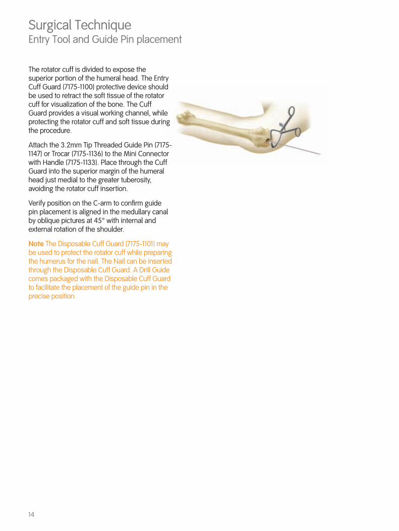
The rotator cuff is divided to expose the superior portion of the humeral head. The Entry Cuff Guard (7175-1100) protective device should be used to retract the soft tissue of the rotator cuff for visualization of the bone. The Cuff Guard provides a visual working channel, while protecting the rotator cuff and soft tissue during the procedure.
Attach the 3.2mm Tip Threaded Guide Pin (7175-1147) or Trocar (7175-1136) to the Mini Connector with Handle (7175-1133). Place through the Cuff Guard into the superior margin of the humeral head just medial to the greater tuberosity, avoiding the rotator cuff insertion.
Verify position on the C-arm to confirm guide pin placement is aligned in the medullary canal by oblique pictures at 45° with internal and external rotation of the shoulder.
Note The Disposable Cuff Guard (7175-1101) may be used to protect the rotator cuff while preparing the humerus for the nail. The Nail can be inserted through the Disposable Cuff Guard. A Drill Guide comes packaged with the Disposable Cuff Guard to facilitate the placement of the guide pin in the precise position.
Surgical Technique Entry Tool and Guide Pin placement

15
Surgical TechniqueInstruments fracture reduction and reaming
Straight Reducer Cat. No. 7175-1105
Straight Ratcheting Driver Cat. No. 7175-1141
2.0mm Graduated Ball Tip Guide Rod Cat. No. 7175-1146
Obturator Cat. No. 7175-1145
Ruler Cat. No. 7175-1126
Fixed Endcutting Reamers (image not shown) Cat. No. 7111-8220 to 7111-8230
Straight entry reamer Cat. No. 7175-1103
Cannulated Awl Cat. No. 7175-1102
16
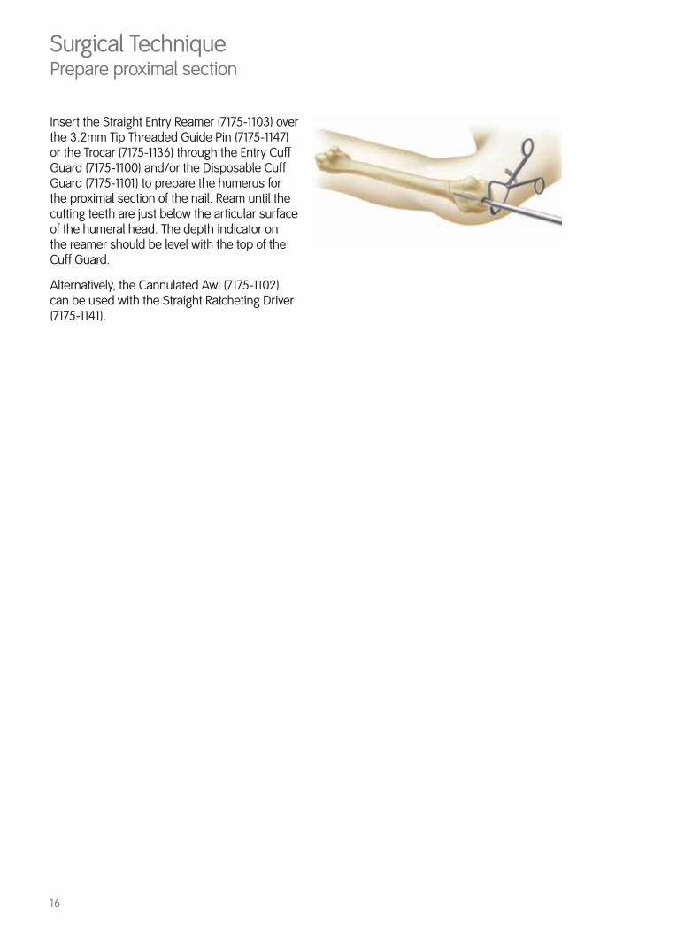
Insert the Straight Entry Reamer (7175-1103) over the 3.2mm Tip Threaded Guide Pin (7175-1147) or the Trocar (7175-1136) through the Entry Cuff Guard (7175-1100) and/or the Disposable Cuff Guard (7175-1101) to prepare the humerus for the proximal section of the nail. Ream until the cutting teeth are just below the articular surface of the humeral head. The depth indicator on the reamer should be level with the top of the Cuff Guard.
Alternatively, the Cannulated Awl (7175-1102) can be used with the Straight Ratcheting Driver (7175-1141).
Surgical TechniquePrepare proximal section

17
After removing the Straight Entry Reamer (7175-1103) and 3.2mm Tip Threaded Guide Pin (7175-1147) or Trocar (7175-1136), insert the Straight Reducer (7175-1105) attached to the Straight Ratcheting Driver (7175-1141) with the slot oriented toward the lateral cortex and reduce the fracture. Place the tip of the finger off the medial cortex to help reduce the fracture.
To maintain reduction, introduce the 2.0mm Graduated Ball Tip Guide Rod (7175-1146) through the Straight Reducer. Center the Guide Rod 1-2cm proximal to the olecranon fossa in the distal end of the humerus. Once the Guide Rod is in place, carefully remove the Straight Reducer, using the Obturator (7175-1145) as needed to ensure the Guide Rod stays in place.
Surgical TechniqueFracture reduction
18
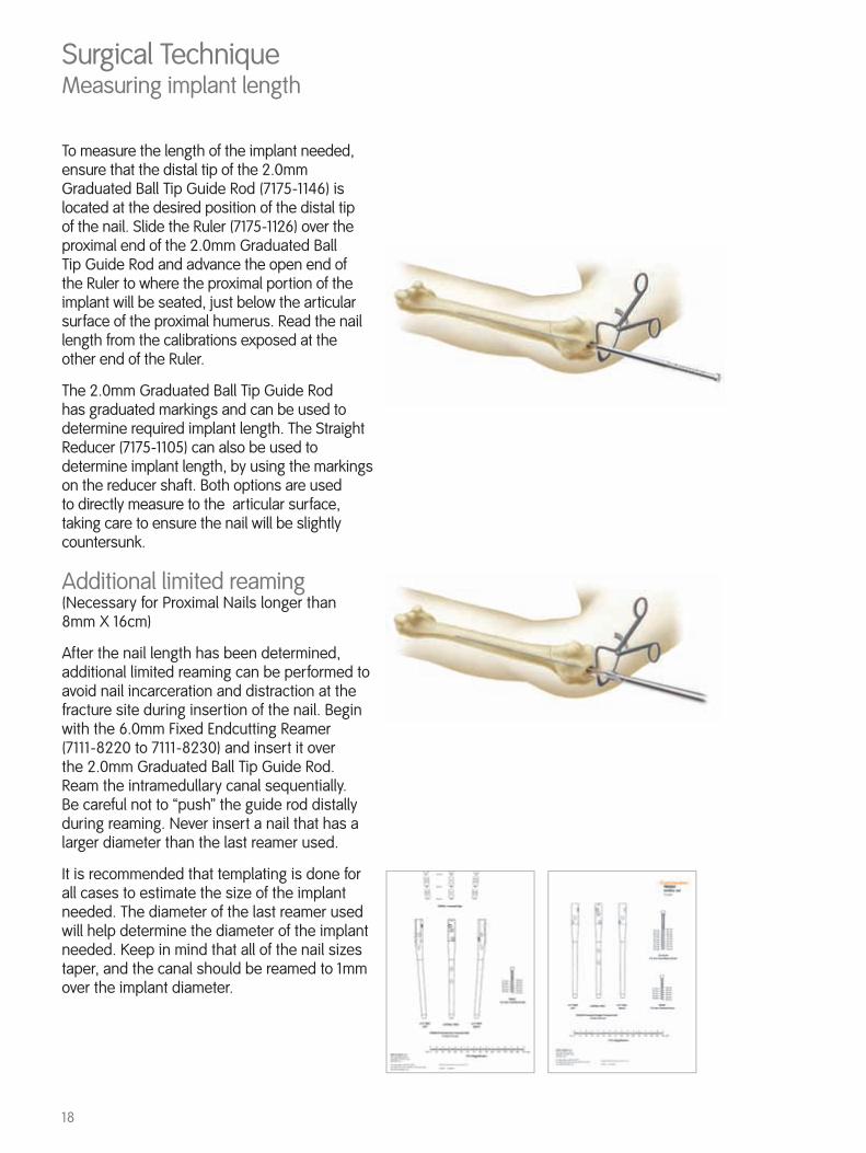
To measure the length of the implant needed, ensure that the distal tip of the 2.0mm Graduated Ball Tip Guide Rod (7175-1146) is located at the desired position of the distal tip of the nail. Slide the Ruler (7175-1126) over the proximal end of the 2.0mm Graduated Ball Tip Guide Rod and advance the open end of the Ruler to where the proximal portion of the implant will be seated, just below the articular surface of the proximal humerus. Read the nail length from the calibrations exposed at the other end of the Ruler.
The 2.0mm Graduated Ball Tip Guide Rod has graduated markings and can be used to determine required implant length. The Straight Reducer (7175-1105) can also be used to determine implant length, by using the markings on the reducer shaft. Both options are used to directly measure to the articular surface, taking care to ensure the nail will be slightly countersunk.
Additional limited reaming(Necessary for Proximal Nails longer than 8mm X 16cm)
After the nail length has been determined, additional limited reaming can be performed to avoid nail incarceration and distraction at the fracture site during insertion of the nail. Begin with the 6.0mm Fixed Endcutting Reamer (7111-8220 to 7111-8230) and insert it over the 2.0mm Graduated Ball Tip Guide Rod. Ream the intramedullary canal sequentially. Be careful not to “push” the guide rod distally during reaming. Never insert a nail that has a larger diameter than the last reamer used.
It is recommended that templating is done for all cases to estimate the size of the implant needed. The diameter of the last reamer used will help determine the diameter of the implant needed. Keep in mind that all of the nail sizes taper, and the canal should be reamed to 1mm over the implant diameter.
Surgical TechniqueMeasuring implant length

19
Surgical TechniqueInstruments for nail assembly and insertion
Humeral Nail Guide Bolt Cat. No. 7175-1108
Nail Drill Guide Cat. No. 7175-1129
Guide Bolt Wrench Cat. No. 7175-1134
Impactor Cat. No. 7175-1133
Proximal Drop Cat. No. 7175-1131
Gold Outer Sleeve Cat. No. 7175-1128
3.2mm Silver Inner Drill Sleeve Cat. No. 7175-1116
3.2mm Long Graduated Two-Flute Drill Cat. No. 7175-1149
Trocar Cat. No. 7175-1136
Anterior Stylus Cat. No. 7175-1130
Humeral Nail Drill Guide Probe Cat. No. 7169-1152

20
Once the implant selection is complete, use the Humeral Nail Guide Bolt (7175-1108) to attach the Nail Drill Guide (7175-1129) to the nail. The nail and Nail Drill Guide are keyed to ensure proper orientation of the nail on the Nail Drill Guide.
Note The metal threads on the proximal locking holes should always be lateral. Tighten the Humeral Nail Guide Bolt using the Guide Bolt Wrench (7175-1134). The Impactor (7175-1133) is then attached to the Humeral Nail Guide Bolt.
To complete the assembly, attach the Proximal Drop (7175-1131) to the lateral arm of the Nail Drill Guide. Tighten the Proximal Drop to the Guide using the knurled knob. Verify targeting accuracy by inserting a Gold Outer Sleeve (7175-1128) and 3.2mm Silver Inner Drill Sleeve (7175-1116) into the drop and passing a 3.2mm Long Graduated Two-Flute Drill (7175-1149) through the assembly. An incorrectly attached nail will not target. The Proximal Drop should be used to target the proximal screws on all Humeral Nails, and the distal screws on the 16cm Proximal Nails. Distal locking screws for the 18cm or longer Humeral Nails should be targeted using the TRIGEN™ SURESHOT™ Distal Targeting System or a freehand technique.
Refer to SURESHOT User Manual for the Field Accuracy check instructions.
Check with the TRIGEN SURESHOT Distal Targeting System.
The Humeral Nail and Nail Drill Guide are keyed to ensure proper orientation of the nail on the Nail Drill Guide.
Surgical TechniqueNail Drill Guide assembly

21
At this point the nail is ready to be inserted. Care should be taken to insert the nail with the correct amount of retroversion and depth in order to maximize locking screw fixation while avoiding critical soft tissues such as the biceps tendon, axillary and radial nerves.
Insert the nail attached to the Nail Drill Guide Assembly over the 2.0mm Graduated Ball Tip Guide Rod (7175-1146) and through the Entry Cuff Guard (7175-1100) with the lateral arm of the drill guide oriented with approximately 30-35° of retroversion. Adjustments to this version can be made so that the anterior arm of the drill guide is in line with the lesser tuberosity, avoiding alignment with the bicipital groove. Proper depth is achieved when the lateral ledge on the drill guide is above the lateral cortex and the nail is seated just below the articular surface.
Remove the Guide Rod from the top of the Nail Drill Guide (7175-1129). Confirm that the fracture is compacted and not distracted.
Surgical TechniqueNail insertion
22
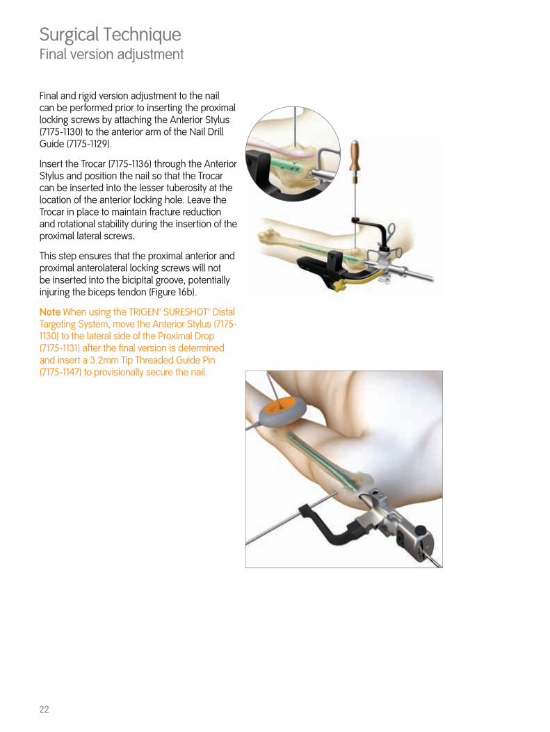
Final and rigid version adjustment to the nail can be performed prior to inserting the proximal locking screws by attaching the Anterior Stylus (7175-1130) to the anterior arm of the Nail Drill Guide (7175-1129).
Insert the Trocar (7175-1136) through the Anterior Stylus and position the nail so that the Trocar can be inserted into the lesser tuberosity at the location of the anterior locking hole. Leave the Trocar in place to maintain fracture reduction and rotational stability during the insertion of the proximal lateral screws.
This step ensures that the proximal anterior and proximal anterolateral locking screws will not be inserted into the bicipital groove, potentially injuring the biceps tendon (Figure 16b).
Note When using the TRIGEN™ SURESHOT™ Distal Targeting System, move the Anterior Stylus (7175-1130) to the lateral side of the Proximal Drop (7175-1131) after the final version is determined and insert a 3.2mm Tip Threaded Guide Pin (7175-1147) to provisionally secure the nail.
Surgical Technique Final version adjustment
23
Surgical p rocedure – TRIGEN™ SURESHOT™ system set up
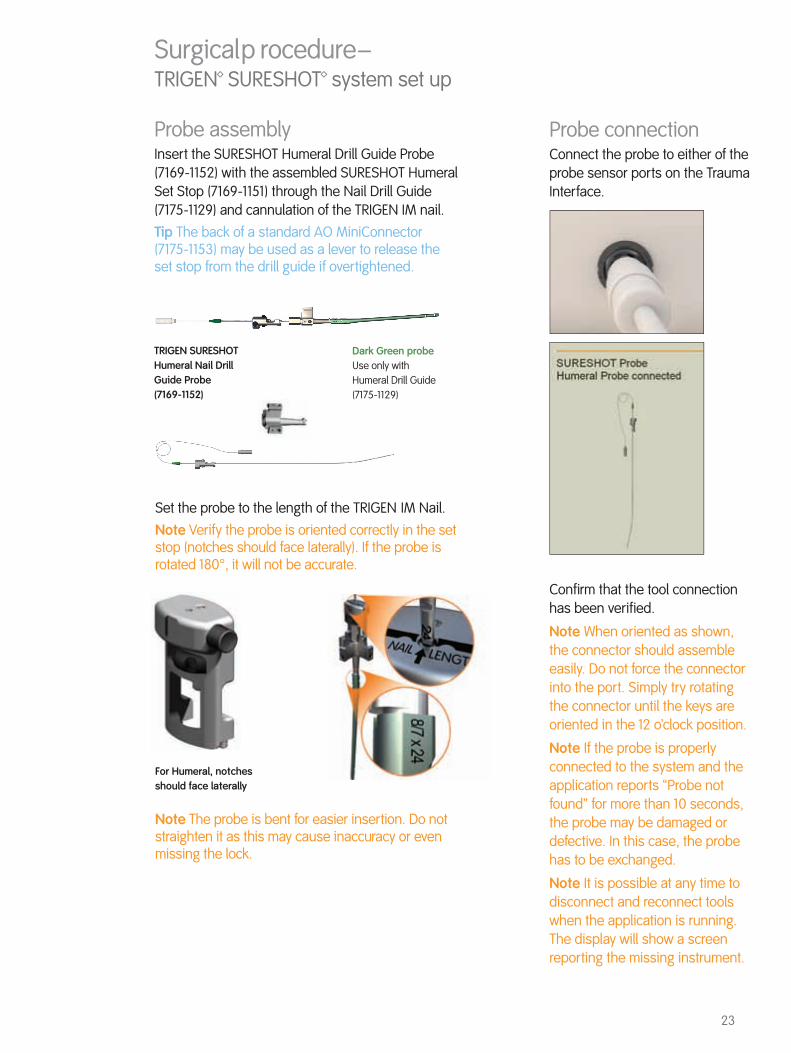
Probe assemblyInsert the SURESHOT Humeral Drill Guide Probe (7169-1152) with the assembled SURESHOT Humeral Set Stop (7169-1151) through the Nail Drill Guide (7175-1129) and cannulation of the TRIGEN IM nail.Tip The back of a standard AO MiniConnector (7175-1153) may be used as a lever to release the set stop from the drill guide if overtightened.
Set the probe to the length of the TRIGEN IM Nail.Note Verify the probe is oriented correctly in the set stop (notches should face laterally). If the probe is rotated 180°, it will not be accurate.
Probe connectionConnect the probe to either of the probe sensor ports on the Trauma Interface.
Confirm that the tool connection has been verified.
Note When oriented as shown, the connector should assemble easily. Do not force the connector into the port. Simply try rotating the connector until the keys are oriented in the 12 o’clock position.
Note If the probe is properly connected to the system and the application reports “Probe not found” for more than 10 seconds, the probe may be damaged or defective. In this case, the probe has to be exchanged.
Note It is possible at any time to disconnect and reconnect tools when the application is running. The display will show a screen reporting the missing instrument.
TRIGEN SURESHOT Humeral Nail Drill Guide Probe (7169-1152)
Dark Green probeUse only with Humeral Drill Guide (7175-1129)
For Humeral, notches should face laterally
Note The probe is bent for easier insertion. Do not straighten it as this may cause inaccuracy or even missing the lock.

24
Drill sleeve selectionSelect the 3.2mm humeral drill sleeve (7169-1154).
Surgical procedure – TRIGEN™ SURESHOT™ system set up
Implant selection screenSelect the TRIGEN IM Nail and size that will be used.Humeral Nail
Note A different TRIGEN IM Nail and/or size can be selected at any time during the procedure by choosing the Implant option from the drop down menu OR by pressing the implant tab located in the lower left corner of the navigation screen.
25
Surgical procedure – after IM Nail Assembly to the Drill Guide
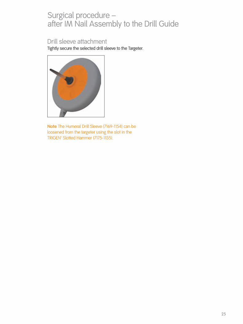
Note The Humeral Drill Sleeve (7169-1154) can be loosened from the targeter using the slot in the TRIGEN™ Slotted Hammer (7175-1135).
Drill sleeve attachmentTightly secure the selected drill sleeve to the Targeter.

26
Skin incisionUse the serrated tip of the SURESHOT Humeral 3.2mm Drill Sleeve (7169-1154) to identify where to make the incision. The tip is at the right position when the green circle is aligned with the desired hole on screen.
Make the incision and place the tip of the drill sleeve down to bone where the green circle is aligned directly over the hole on the screen.
Note No X-Rays are necessary.
Surgical TechniqueSkin incision with TRIGEN™ SURESHOT™

27
With the TRIGEN™ SURESHOT™ Humeral 3.2mm AO Drill (7169-1155) inserted into the TRIGEN SURESHOT Targeter (7169-2801), insert the tip of the SURESHOT Humeral 3.2mm Drill Sleeve (7169-1154) (represented by the green circle) through the incision and down to bone.
Perfect circlesAlign the tip of the drill sleeve over the desired hole in the nail. This will be represented on the screen when the green circle is centered in the hole as shown. Push the serrated tip firmly against bone to keep the green circle static on the screen.
Adjust the trajectory (represented by red line between two circles) of the red circle until both circles are concentric and centered with the desired hole on the screen. Then start drilling.
Critical Verify there are no other metal objects (including metal triangles) in the field. Metal interference will cause the system to be inaccurate.
Surgical TechniqueTargeting the locking hole
Note The green circle must be fully within the hole of the IM nail displayed on the Trauma Interface screen to ensure accurate drilling.
Tibia shown in image
28
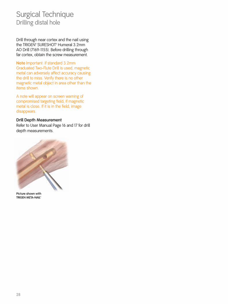
Drill through near cortex and the nail using the TRIGEN™ SURESHOT™ Humeral 3.2mm AO Drill (7169-1155). Before drilling through far cortex, obtain the screw measurement.
Note Important: if standard 3.2mm Graduated Two-Flute Drill is used, magnetic metal can adversely affect accuracy causing the drill to miss. Verify there is no other magnetic metal object in area other than the items shown.
A note will appear on screen warning of compromised targeting field, if magnetic metal is close. If it is in the field, image disappears.
Drill Depth MeasurementRefer to User Manual Page 16 and 17 for drill depth measurements.
Picture shown with TRIGEN META-NAIL™
Surgical TechniqueDrilling distal hole

29
Surgical Technique Screw insertionUsing the TRIGEN™ SURESHOT™ Hexdriver (7169-1153), the screw may be inserted using the Targeter.
WARNING The standard TRIGEN Hexdrivers are made from magnetic stainless steel that will cause interference with the system and cannot be used.

30
Surgical TechniqueInstruments for proximal locking, distal locking of Proximal 16cm Humeral Nails and freehand distal locking
Proximal Drop Cat. No. 7175-1131
Nail Drill Guide Cat. No. 7175-1129
Trocar Cat. No. 7175-1136
3.2mm Long Graduated Two-Flute Drill Cat. No. 7175-1149
Screw Depth Gauge Cat. No. 7175-1139
3.5mm Hex Driver Cat. No. 7175-1140
Straight Ratcheting Driver Cat. No. 7175-1141
Screw Length Sleeve Cat. No. 11-0238
Gold Outer Sleeve Cat. No. 7175-1128
3.2mm Silver Inner Drill Sleeve Cat. No. 7175-1116

31
Note The Proximal Drop (7175-1131) only targets the distal holes for the 16cm nails. Nails longer than 16cm will be targeted using the freehand technique or TRIGEN SURESHOT™ Distal Targeting System.
With the Proximal Drop connected to the lateral arm of the Nail Drill Guide (7175-1129), place the 3.2mm Silver Inner Drill Sleeve (7175-1116) into the Gold Outer Sleeve (7175-1128). Insert the sleeve unit into the targeting hole in the Proximal Drop which corresponds to the superior M/L distal locking hole in the nail. While applying compression at the condyles of the elbow to reduce shaft fractures as needed, make a stab incision and push the sleeve unit down to the bone. The Trocar (7175-1136), in combination with the drill sleeve unit, may be used to dimple the cortex. Drill through both cortices using the 3.2mm Long Graduated Two-Flute Drill (7175-1149). A length measurement can be taken from the calibrations on the drill against the 3.2mm Silver Inner Drill Sleeve, or the Screw Depth Gauge (7175-1139) can be used through the Gold Outer Sleeve to measure for distal locking screws.
Once the appropriate length 4.0mm Self-Tapping Cortical Screw is selected, it is attached to the 3.5mm Hex Driver. The screw is inserted through the Gold Outer Sleeve using the 3.5mm Hex Driver (7175-1140). The head of the screw should be nearly seated when the laser-marked ring on the Hex Driver is even with the Gold Outer Sleeve. Final tightening of the screw should always be performed manually using the Straight Ratcheting Driver (7175-1141). Repeat this process for the inferior distal screw.
Surgical TechniqueDistal locking screws for TRIGEN™ Proximal 16cm Humeral Nails
32
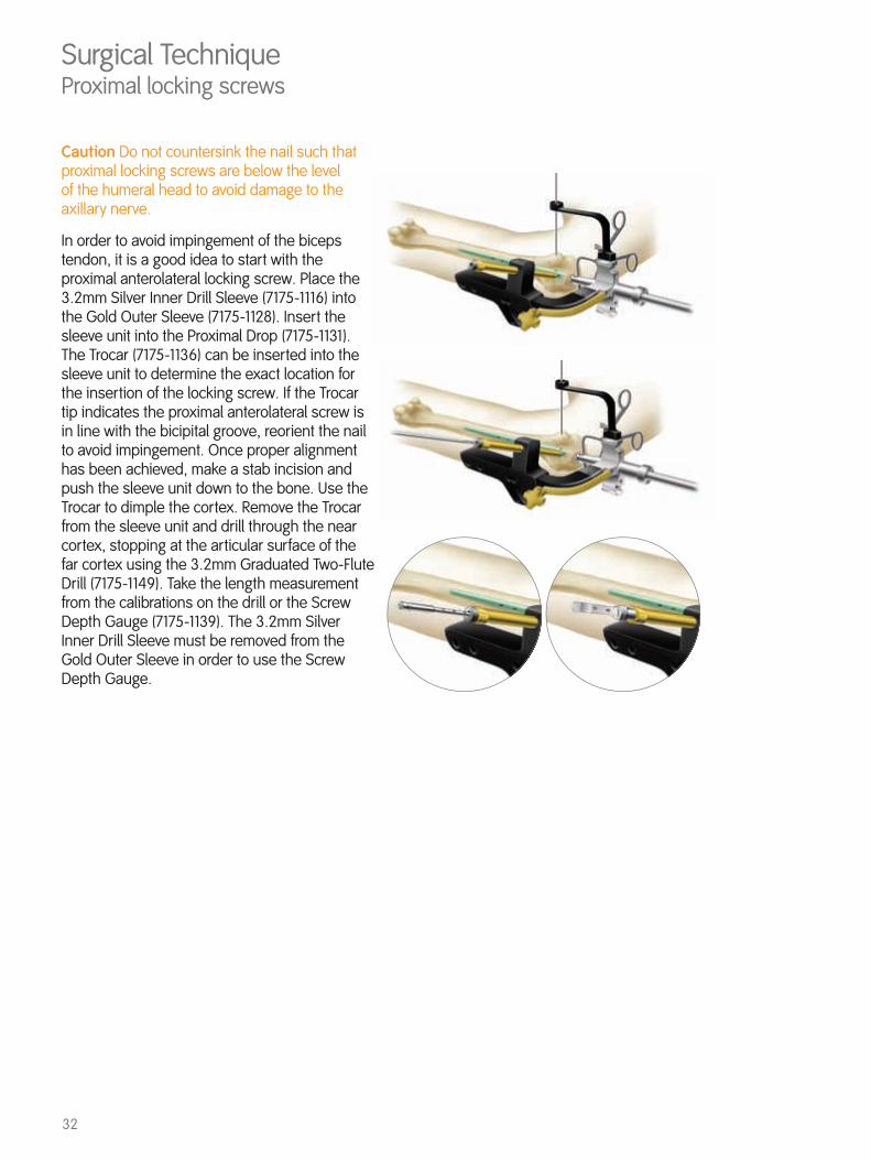
Caution Do not countersink the nail such that proximal locking screws are below the level of the humeral head to avoid damage to the axillary nerve.
In order to avoid impingement of the biceps tendon, it is a good idea to start with the proximal anterolateral locking screw. Place the 3.2mm Silver Inner Drill Sleeve (7175-1116) into the Gold Outer Sleeve (7175-1128). Insert the sleeve unit into the Proximal Drop (7175-1131). The Trocar (7175-1136) can be inserted into the sleeve unit to determine the exact location for the insertion of the locking screw. If the Trocar tip indicates the proximal anterolateral screw is in line with the bicipital groove, reorient the nail to avoid impingement. Once proper alignment has been achieved, make a stab incision and push the sleeve unit down to the bone. Use the Trocar to dimple the cortex. Remove the Trocar from the sleeve unit and drill through the near cortex, stopping at the articular surface of the far cortex using the 3.2mm Graduated Two-Flute Drill (7175-1149). Take the length measurement from the calibrations on the drill or the Screw Depth Gauge (7175-1139). The 3.2mm Silver Inner Drill Sleeve must be removed from the Gold Outer Sleeve in order to use the Screw Depth Gauge.
Surgical TechniqueProximal locking screws
33
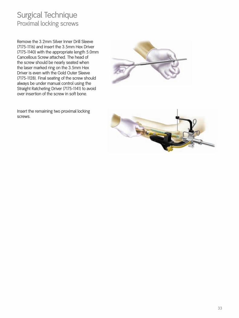
Remove the 3.2mm Silver Inner Drill Sleeve (7175-1116) and insert the 3.5mm Hex Driver (7175-1140) with the appropriate length 5.0mm Cancellous Screw attached. The head of the screw should be nearly seated when the laser marked ring on the 3.5mm Hex Driver is even with the Gold Outer Sleeve (7175-1128). Final seating of the screw should always be under manual control using the Straight Ratcheting Driver (7175-1141) to avoid over insertion of the screw in soft bone.
Insert the remaining two proximal locking screws.
Surgical TechniqueProximal locking screws
34
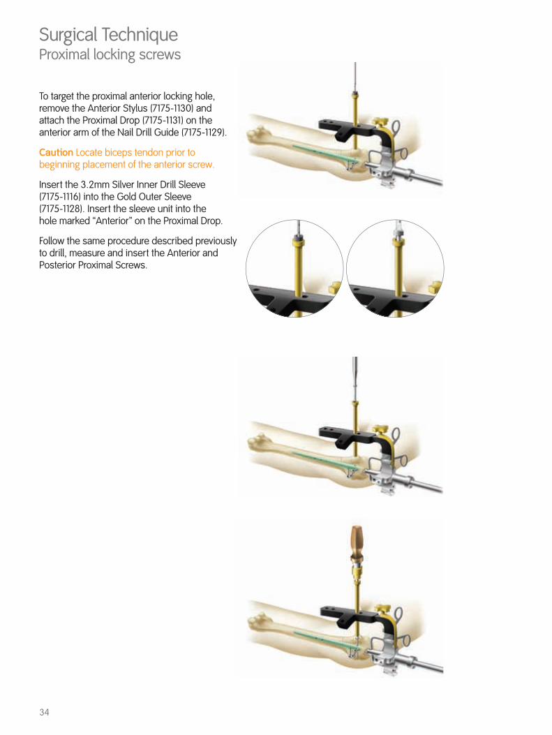
To target the proximal anterior locking hole, remove the Anterior Stylus (7175-1130) and attach the Proximal Drop (7175-1131) on the anterior arm of the Nail Drill Guide (7175-1129).
Caution Locate biceps tendon prior to beginning placement of the anterior screw.
Insert the 3.2mm Silver Inner Drill Sleeve (7175-1116) into the Gold Outer Sleeve (7175-1128). Insert the sleeve unit into the hole marked “Anterior” on the Proximal Drop.
Follow the same procedure described previously to drill, measure and insert the Anterior and Posterior Proximal Screws.
Surgical TechniqueProximal locking screws
35
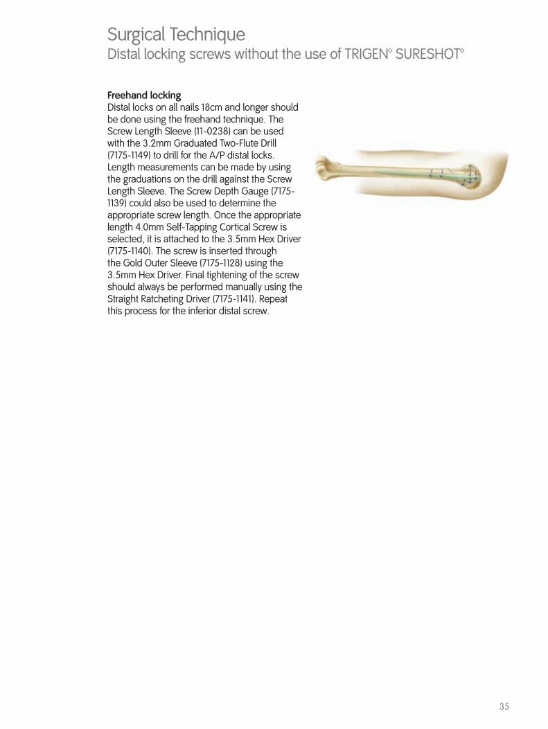
Freehand lockingDistal locks on all nails 18cm and longer should be done using the freehand technique. The Screw Length Sleeve (11-0238) can be used with the 3.2mm Graduated Two-Flute Drill (7175-1149) to drill for the A/P distal locks. Length measurements can be made by using the graduations on the drill against the Screw Length Sleeve. The Screw Depth Gauge (7175-1139) could also be used to determine the appropriate screw length. Once the appropriate length 4.0mm Self-Tapping Cortical Screw is selected, it is attached to the 3.5mm Hex Driver (7175-1140). The screw is inserted through the Gold Outer Sleeve (7175-1128) using the 3.5mm Hex Driver. Final tightening of the screw should always be performed manually using the Straight Ratcheting Driver (7175-1141). Repeat this process for the inferior distal screw.
Surgical TechniqueDistal locking screws without the use of TRIGEN™ SURESHOT™
36
Close the wound in layers, use nonresorbable sutures in the rotator cuff repair. Close the remainder of the incision in a standard fashion.
Removal of the nailThe Screw Head Trephine (7175-1144), the Proximal Nail Trephine (7175-1143) and the Extractor (7175-1142) are included in the instrument set to facilitate nail removal.
Surgical TechniqueClosure

37
TRIGEN Long Bent Humeral Nail
TRIGEN Proximal Straight Humeral NailCat. No. Size Length
7176-0816 8/7mm 16cm
TRIGEN Humeral Nail Cap(Not Shown)Cat. No. 7176-0000
TRIGEN Proximal Bent Humeral NailCat. No. Size Length
7177-0816 8/7mm 16cm
5.0mm Self-Tapping Cancellous Screw
4.0mm Self-Tapping Cortical ScrewCat. No. Length 7175-4020 20mm 7175-4022 22mm 7175-4024 24mm 7175-4026 26mm 7175-4028 28mm 7175-4030 30mm
Cat. No. Length 7175-4032 32mm 7175-4034 34mm 7175-4036 36mm 7175-4038 38mm 7175-4040 40mm
Cat. No. Length 7175-5024 24mm 7175-5026 26mm 7175-5028 28mm 7175-5030 30mm 7175-5032 32mm 7175-5034 34mm 7175-5036 36mm 7175-5038 38mm 7175-5040 40mm 7175-5042 42mm 7175-5044 44mm
Cat. No. Length 7175-5046 46mm 7175-5048 48mm 7175-5050 50mm 7175-5052 52mm 7175-5054 54mm 7175-5056 56mm 7175-5058 58mm7175-5060 60mm 7175-5062 62mm 7175-5064 64mm
Cat. No. Size Length 7177-0818 8/7mm 18cm 7177-0820 8/7mm 20cm 7177-0822 8/7mm 22cm 7177-0824 8/7mm 24cm 7177-0826 8/7mm 26cm 7177-0828 8/7mm 28cm 7177-0918 9/7.5mm 18cm 7177-0920 9/7.5mm 20cm 7177-0922 9/7.5mm 22cm
Cat. No. Size Length7177-0924 9/7.5mm 24cm 7177-0926 9/7.5mm 26cm 7177-0928 9/7.5mm 28cm7177-1018 10/8.5mm 18cm 7177-1020 10/8.5mm 20cm 7177-1022 10/8.5mm 22cm7177-1024 10/8.5mm 24cm 7177-1026 10/8.5mm 26cm 7177-1028 10/8.5mm 28cm
Catalog informationTRIGEN™ Humeral Nail Implants
TRIGEN Humeral Nail Implant Set Set No. 7175-0703
38
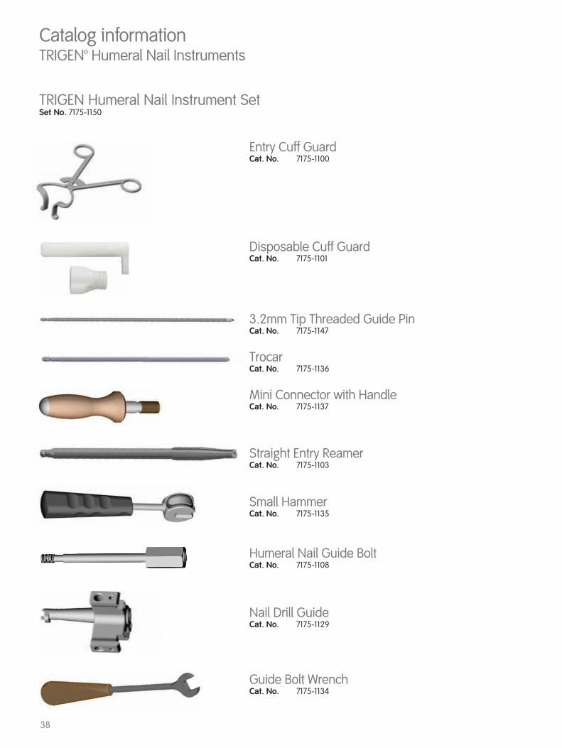
TrocarCat. No. 7175-1136
3.2mm Tip Threaded Guide PinCat. No. 7175-1147
Straight Entry ReamerCat. No. 7175-1103
Entry Cuff GuardCat. No. 7175-1100
Mini Connector with HandleCat. No. 7175-1137
Small HammerCat. No. 7175-1135
Humeral Nail Guide BoltCat. No. 7175-1108
Nail Drill GuideCat. No. 7175-1129
Guide Bolt WrenchCat. No. 7175-1134
Catalog informationTRIGEN™ Humeral Nail Instruments
Disposable Cuff GuardCat. No. 7175-1101
TRIGEN Humeral Nail Instrument Set Set No. 7175-1150

39
3.2mm Silver Inner Drill SleeveCat. No. 7175-1116
Straight Ratcheting DriverCat. No. 7175-1141
ImpactorCat. No. 7175-1133
Anterior StylusCat. No. 7175-1130
Proximal DropCat. No. 7175-1131
Straight ReducerCat. No. 7175-1105
ObturatorCat. No. 7175-1145
*2.0mm x 600mm Graduated 3.2mm Ball Tip Guide Rod Cat. No. 7175-1146
RulerCat. No. 7175-1126
Catalog informationTRIGEN™ Humeral Nail Instruments
Fixed Endcutting ReamersSize Cat. No. 6.0mm 7111-82207.0mm 7111-82228.0mm 7111-82249.0mm 7111-822610.0mm 7111-822811.0mm 7111-8230
image not shown
*Dedicated to Humeral nail only, cannot be used with other TRIGEN systems (HFN)

40
Catalog informationTRIGEN™ Humeral Nail Instruments
Screw Head TrephineCat. No. 7175-1144
Gold Outer SleeveCat. No. 7175-1128
Screw Depth GaugeCat. No. 7175-1139
3.5mm Hex DriverCat. No. 7175-1140
Mini ConnectorCat. No. 7163-1186
AO Mini ConnectorCat. No. 7175-1153
Trinkle ConnectorCat. No. 7163-1187
Proximal Nail TrephineCat. No. 7175-1143
ExtractorCat. No. 7175-1142
Cannulated AwlCat. No. 7175-1102
3.2mm Graduated Two-Flute DrillDescription Cat. No. Short 7175-1148Long 7175-1149
41
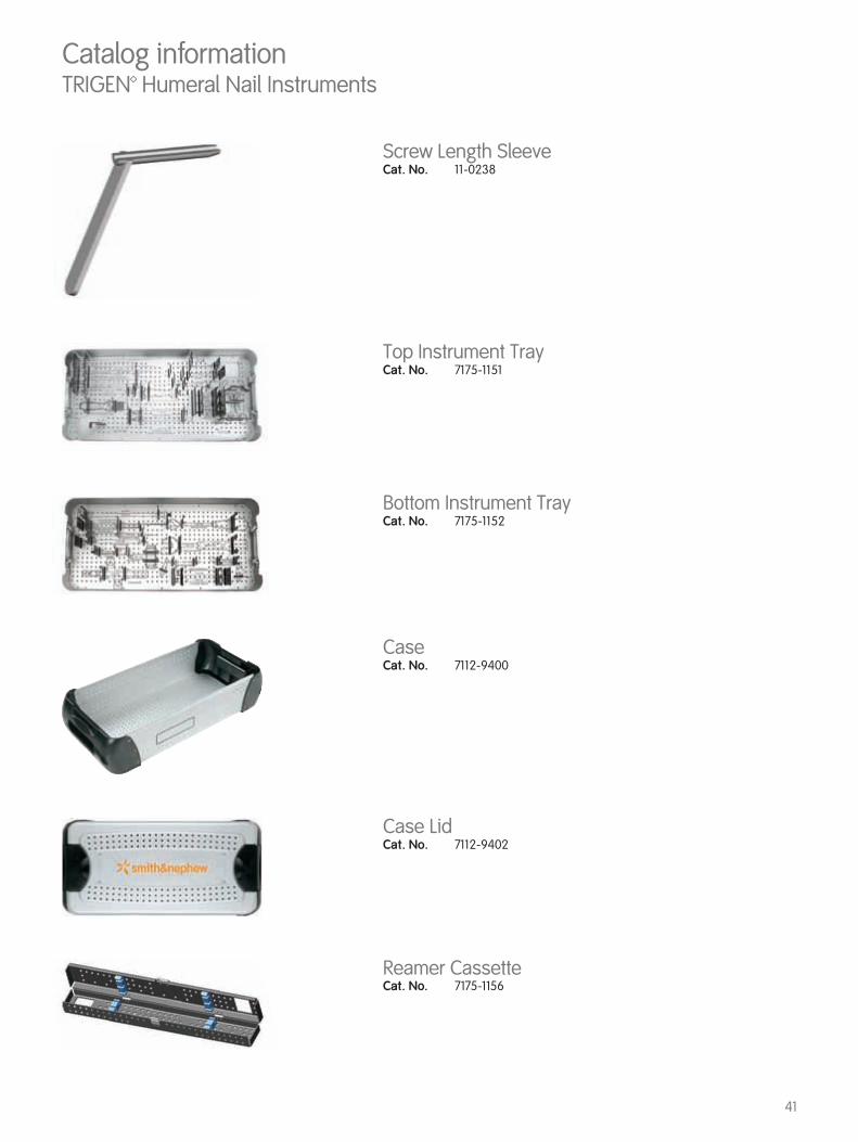
Screw Length SleeveCat. No. 11-0238
Reamer CassetteCat. No. 7175-1156
Catalog informationTRIGEN™ Humeral Nail Instruments
Case LidCat. No. 7112-9402
CaseCat. No. 7112-9400
Top Instrument TrayCat. No. 7175-1151
Bottom Instrument TrayCat. No. 7175-1152

42
TRIGEN SURESHOT Targeting InterfaceCat. No. 7165-7000
Cat. No. Device Case Qty7169-2802 Trauma Interface 1
TRIGEN SURESHOT Targeting Instrument SetSet No. 7165-7001
Cat. No. Description Tray Qty
7169-2801 Targeter 17169-2804 Drill Sleeve - Long 27169-2805 Drill Sleeve - Short 27169-2806 META Set Stop 17169-2807 TAN™ Set Stop 17169-2808 Field Accuracy Gauge 17169-2809 Hexdriver 17169-2816 TAN Anteversion Locking Guide 17169-2830 Targeting Instrument Tray 17169-2831 Targeting Instrument Tray Lid 1
TRIGEN SURESHOT Humeral Instrument Set Set No. 7165-1100
Cat. No. Description Qty7169-1151 SURESHOT Humeral Set Stop 17169-1153 SURESHOT Humeral 3.5mm Hexdriver 17169-1154 SURESHOT Humeral 3.2mm Drill Sleeve 27169-1156 SURESHOT Humeral Instrument Caddy 1
TRIGEN SURESHOT Humeral Disposable Set Set No. 7165-1101
Cat. No. Description Qty7169-1152 SURESHOT Humeral Drill Guide Probe 27169-1155 SURESHOT Humeral 3.2mm AO Drill 2
Catalog informationTRIGEN™ SURESHOT™ Instruments
43
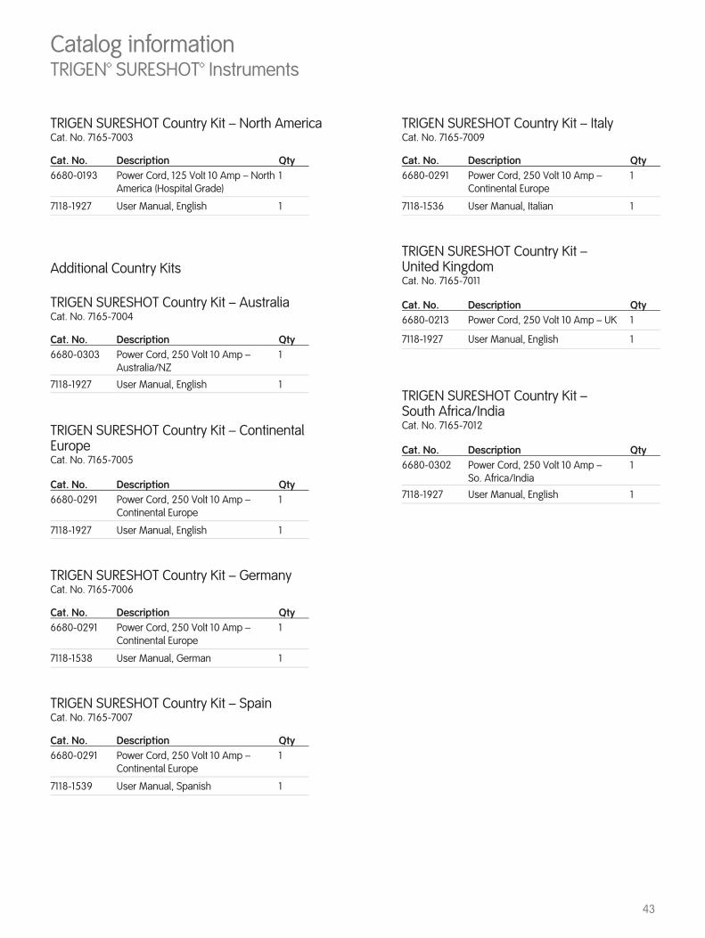
TRIGEN SURESHOT Country Kit – North AmericaCat. No. 7165-7003
Additional Country Kits
TRIGEN SURESHOT Country Kit – AustraliaCat. No. 7165-7004
TRIGEN SURESHOT Country Kit – GermanyCat. No. 7165-7006
TRIGEN SURESHOT Country Kit – SpainCat. No. 7165-7007
TRIGEN SURESHOT Country Kit – Continental EuropeCat. No. 7165-7005
Cat. No. Description Qty6680-0193 Power Cord, 125 Volt 10 Amp – North
America (Hospital Grade)1
7118-1927 User Manual, English 1
Cat. No. Description Qty6680-0303 Power Cord, 250 Volt 10 Amp –
Australia/NZ1
7118-1927 User Manual, English 1
Cat. No. Description Qty6680-0291 Power Cord, 250 Volt 10 Amp –
Continental Europe1
7118-1538 User Manual, German 1
Cat. No. Description Qty6680-0291 Power Cord, 250 Volt 10 Amp –
Continental Europe1
7118-1539 User Manual, Spanish 1
Cat. No. Description Qty6680-0291 Power Cord, 250 Volt 10 Amp –
Continental Europe1
7118-1927 User Manual, English 1
Catalog informationTRIGEN™ SURESHOT™ Instruments
TRIGEN SURESHOT Country Kit – ItalyCat. No. 7165-7009
TRIGEN SURESHOT Country Kit – United KingdomCat. No. 7165-7011
TRIGEN SURESHOT Country Kit – South Africa/IndiaCat. No. 7165-7012
Cat. No. Description Qty6680-0291 Power Cord, 250 Volt 10 Amp –
Continental Europe1
7118-1536 User Manual, Italian 1
Cat. No. Description Qty6680-0213 Power Cord, 250 Volt 10 Amp – UK 1
7118-1927 User Manual, English 1
Cat. No. Description Qty6680-0302 Power Cord, 250 Volt 10 Amp –
So. Africa/India1
7118-1927 User Manual, English 1

44
Smith & Nephew, Inc.7135 Goodlett Farms ParkwayCordova, TN 38016USA
Telephone: 1-901-396-2121Information: 1-800-821-5700Orders and Inquiries: 1-800-238-7538
™ Trademark of Smith & Nephew. Certain marks Reg. US Pat. & TM Off.
www.smith-nephew.com
© 2014 Smith & Nephew, Inc. All rights reserved. 01363 V1 71181802 REVB 01/14


![ZZ - fiqhulhadith.com ki kunjyan.pdf69 ----- *****™™*™™ÒÃÃÃÅÅÅÃÅääää™™™™]]]!!!!***hZZZå 71 -----*****™™™*™ÀÀÀÀÂÂÂÂ6666,,,vvvvZZZ{{{Z{ŠŠŠŠcc**c](https://img.pdfslide.tips/doc/110x75/5e5e26f29bdb1829b545ee7d/zz-ki-kunjyanpdf-69-aaaaffffaaaahzzz.jpg)