Embed Size (px)
Citation preview
OpenStax-CNX module: m42390 1
Induced Emf and Magnetic Flux*
OpenStax
This work is produced by OpenStax-CNX and licensed under the
Creative Commons Attribution License 4.0�
Abstract
• Calculate the �ux of a uniform magnetic �eld through a loop of arbitrary orientation.• Describe methods to produce an electromotive force (emf) with a magnetic �eld or magnet and a
loop of wire.
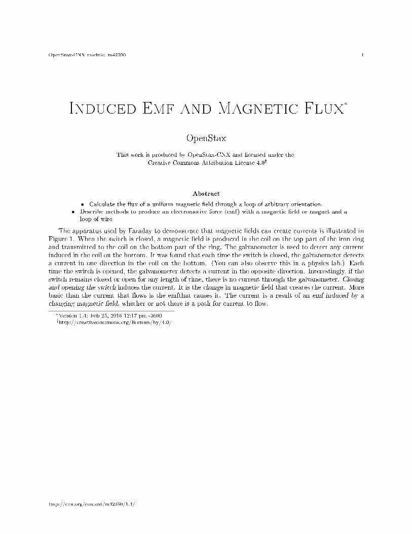
The apparatus used by Faraday to demonstrate that magnetic �elds can create currents is illustrated inFigure 1. When the switch is closed, a magnetic �eld is produced in the coil on the top part of the iron ringand transmitted to the coil on the bottom part of the ring. The galvanometer is used to detect any currentinduced in the coil on the bottom. It was found that each time the switch is closed, the galvanometer detectsa current in one direction in the coil on the bottom. (You can also observe this in a physics lab.) Eachtime the switch is opened, the galvanometer detects a current in the opposite direction. Interestingly, if theswitch remains closed or open for any length of time, there is no current through the galvanometer. Closingand opening the switch induces the current. It is the change in magnetic �eld that creates the current. Morebasic than the current that �ows is the emfthat causes it. The current is a result of an emf induced by a
changing magnetic �eld, whether or not there is a path for current to �ow.
*Version 1.4: Feb 25, 2016 12:17 pm -0600�http://creativecommons.org/licenses/by/4.0/
http://cnx.org/content/m42390/1.4/
OpenStax-CNX module: m42390 2
Figure 1: Faraday's apparatus for demonstrating that a magnetic �eld can produce a current. A changein the �eld produced by the top coil induces an emf and, hence, a current in the bottom coil. When theswitch is opened and closed, the galvanometer registers currents in opposite directions. No current �owsthrough the galvanometer when the switch remains closed or open.
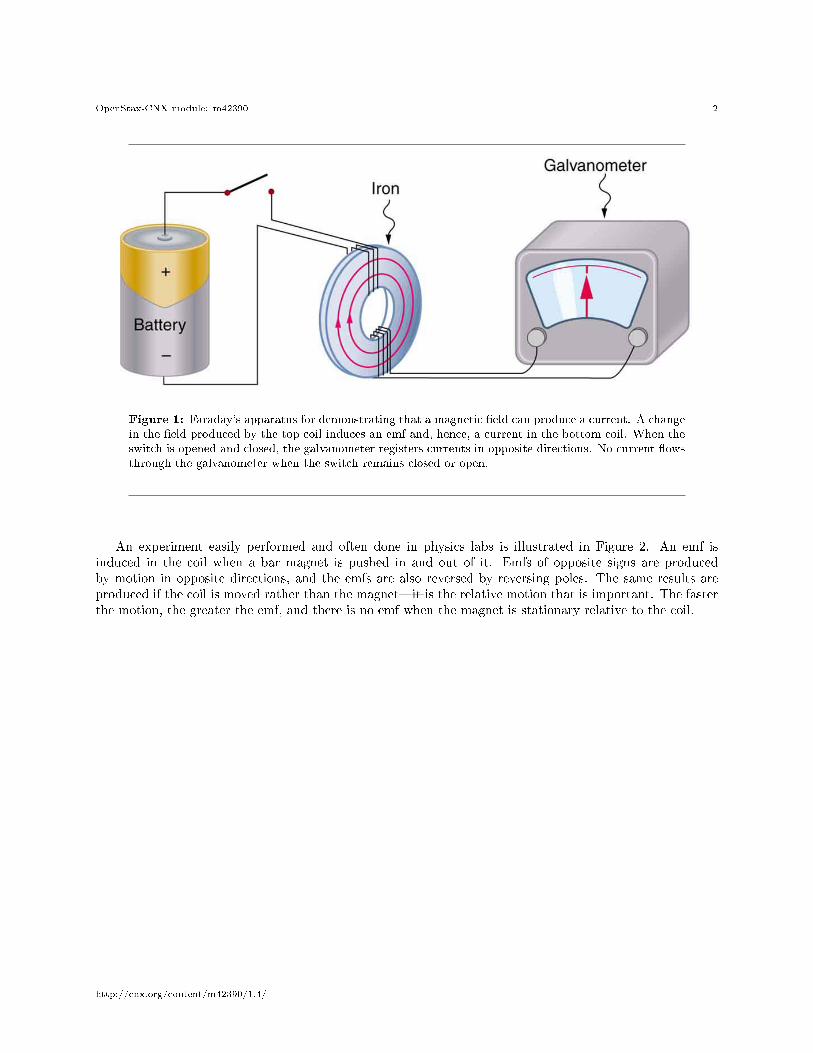
An experiment easily performed and often done in physics labs is illustrated in Figure 2. An emf isinduced in the coil when a bar magnet is pushed in and out of it. Emfs of opposite signs are producedby motion in opposite directions, and the emfs are also reversed by reversing poles. The same results areproduced if the coil is moved rather than the magnet�it is the relative motion that is important. The fasterthe motion, the greater the emf, and there is no emf when the magnet is stationary relative to the coil.
http://cnx.org/content/m42390/1.4/
OpenStax-CNX module: m42390 3
Figure 2: Movement of a magnet relative to a coil produces emfs as shown. The same emfs are producedif the coil is moved relative to the magnet. The greater the speed, the greater the magnitude of the emf,and the emf is zero when there is no motion.
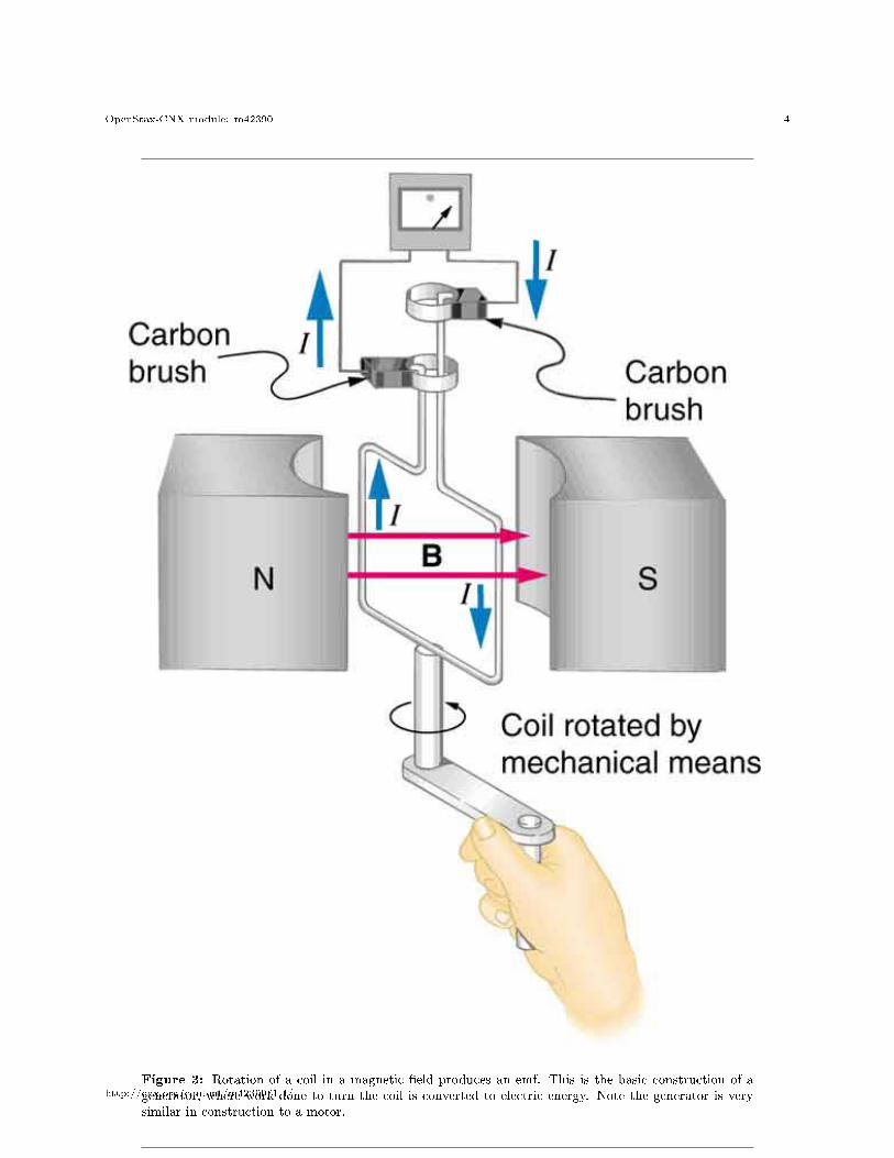
The method of inducing an emf used in most electric generators is shown in Figure 3. A coil is rotatedin a magnetic �eld, producing an alternating current emf, which depends on rotation rate and other factorsthat will be explored in later sections. Note that the generator is remarkably similar in construction to amotor (another symmetry).
http://cnx.org/content/m42390/1.4/
OpenStax-CNX module: m42390 4
Figure 3: Rotation of a coil in a magnetic �eld produces an emf. This is the basic construction of agenerator, where work done to turn the coil is converted to electric energy. Note the generator is verysimilar in construction to a motor.
http://cnx.org/content/m42390/1.4/
OpenStax-CNX module: m42390 5
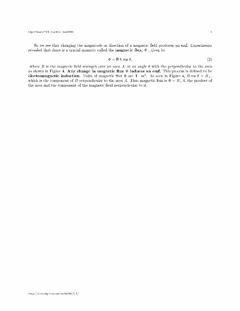
So we see that changing the magnitude or direction of a magnetic �eld produces an emf. Experimentsrevealed that there is a crucial quantity called the magnetic �ux, Φ , given by
Φ = BA cos θ, (3)
where B is the magnetic �eld strength over an area A, at an angle θ with the perpendicular to the areaas shown in Figure 4. Any change in magnetic �ux Φ induces an emf. This process is de�ned to beelectromagnetic induction. Units of magnetic �ux Φ are T · m2. As seen in Figure 4, B cos θ = B⊥,which is the component of B perpendicular to the area A. Thus magnetic �ux is Φ = B⊥A, the product ofthe area and the component of the magnetic �eld perpendicular to it.
http://cnx.org/content/m42390/1.4/
OpenStax-CNX module: m42390 6
Figure 4: Magnetic �ux Φ is related to the magnetic �eld and the area over which it exists. The �uxΦ = BA cos θ is related to induction; any change in Φ induces an emf.
All induction, including the examples given so far, arises from some change in magnetic �ux Φ. Forexample, Faraday changed B and hence Φ when opening and closing the switch in his apparatus (shown inFigure 1). This is also true for the bar magnet and coil shown in Figure 2. When rotating the coil of agenerator, the angle θ and, hence, Φ is changed. Just how great an emf and what direction it takes dependon the change in Φ and how rapidly the change is made, as examined in the next section.
http://cnx.org/content/m42390/1.4/
OpenStax-CNX module: m42390 7
1 Section Summary
• The crucial quantity in induction is magnetic �ux Φ, de�ned to be Φ = BA cos θ, where B is themagnetic �eld strength over an area A at an angle θ with the perpendicular to the area.
• Units of magnetic �ux Φ are T ·m2.• Any change in magnetic �ux Φ induces an emf�the process is de�ned to be electromagnetic induction.
2 Conceptual Questions
Exercise 1How do the multiple-loop coils and iron ring in the version of Faraday's apparatus shown in Figure 1enhance the observation of induced emf?
Exercise 2When a magnet is thrust into a coil as in Figure 2(a), what is the direction of the force exerted bythe coil on the magnet? Draw a diagram showing the direction of the current induced in the coiland the magnetic �eld it produces, to justify your response. How does the magnitude of the forcedepend on the resistance of the galvanometer?
Exercise 3Explain how magnetic �ux can be zero when the magnetic �eld is not zero.
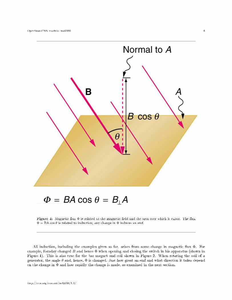
Exercise 4Is an emf induced in the coil in Figure 5 when it is stretched? If so, state why and give the directionof the induced current.
Figure 5: A circular coil of wire is stretched in a magnetic �eld.
3 Problems & Exercises
Exercise 5 (Solution on p. 9.)
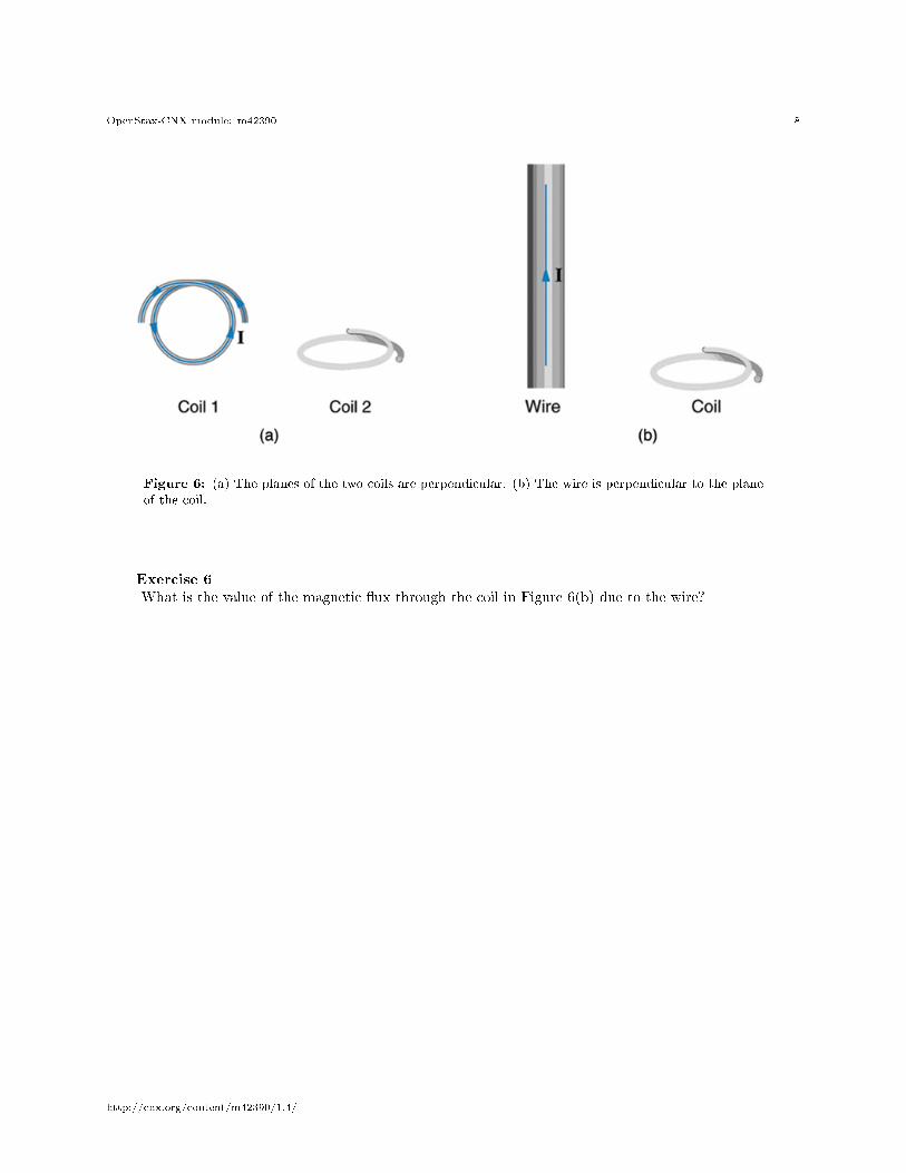
What is the value of the magnetic �ux at coil 2 in Figure 6 due to coil 1?
http://cnx.org/content/m42390/1.4/
OpenStax-CNX module: m42390 8
Figure 6: (a) The planes of the two coils are perpendicular. (b) The wire is perpendicular to the planeof the coil.
Exercise 6What is the value of the magnetic �ux through the coil in Figure 6(b) due to the wire?
http://cnx.org/content/m42390/1.4/
OpenStax-CNX module: m42390 9
Solutions to Exercises in this Module
Solution to Exercise (p. 7)Zero
Glossary
De�nition 6: magnetic �uxthe amount of magnetic �eld going through a particular area, calculated with Φ = BA cos θ whereB is the magnetic �eld strength over an area A at an angle θ with the perpendicular to the area
De�nition 6: electromagnetic inductionthe process of inducing an emf (voltage) with a change in magnetic �ux
http://cnx.org/content/m42390/1.4/


![Funksies en Grafieke - Graad 10 [CAPS] - CNX...OpenStax-CNX module: m38517 1 Funksies en Grafieke - Graad 10 [CAPS] * reeF High School Science Texts Project Based on unctionsF and](https://img.pdfslide.tips/doc/110x75/60f7959ea7892f4482323e6d/funksies-en-grafieke-graad-10-caps-cnx-openstax-cnx-module-m38517-1-funksies.jpg)