Embed Size (px)
Citation preview
Inertial Sensor and Its Applicati
on for Space Fundamental Expe
riments
Ze-Bing Zhou (周泽兵 ), Jun Luo (罗俊 )
Center for Gravitational Experiment,
Huazhong University of Science and Techn
ology
3rd ASTROD, 14-17 July, 2006, Beijing
2
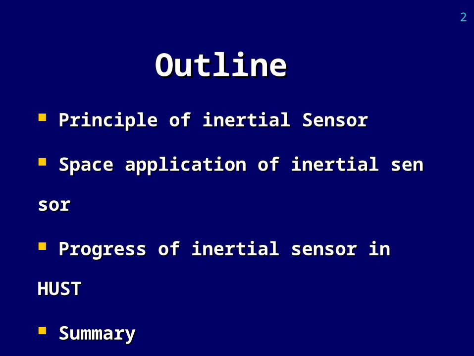
OutlineOutline
Principle of inertial SensorPrinciple of inertial Sensor
Space application of inertial sensorSpace application of inertial sensor
Progress of inertial sensor in HUSTProgress of inertial sensor in HUST
SummarySummary
3
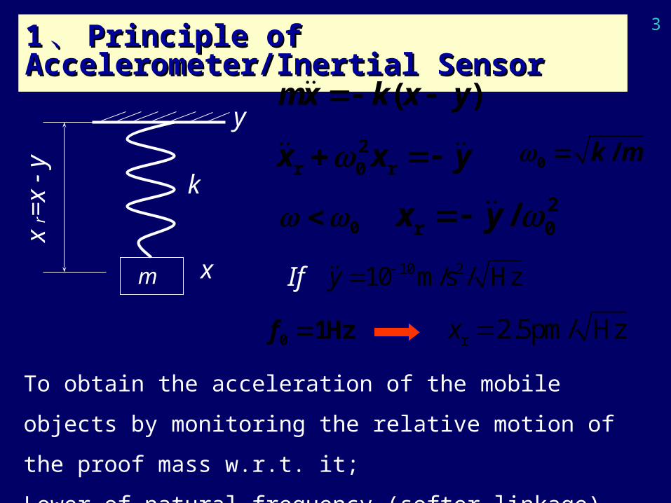
11 、、 Principle of Accelerometer/Inertial Principle of Accelerometer/Inertial SensorSensor
2r 0 rx x y
0 2r 0/x y
xr =
x -
y
k
m
y
x If 10 210 m/s / Hzy
Hz10 f r 2.5pm/ Hzx
To obtain the acceleration of the mobile objects by monitoring the
relative motion of the proof mass w.r.t. it;
Lower of natural frequency (softer linkage), higher sensitivity
)( yxkxm
0 /k m
4
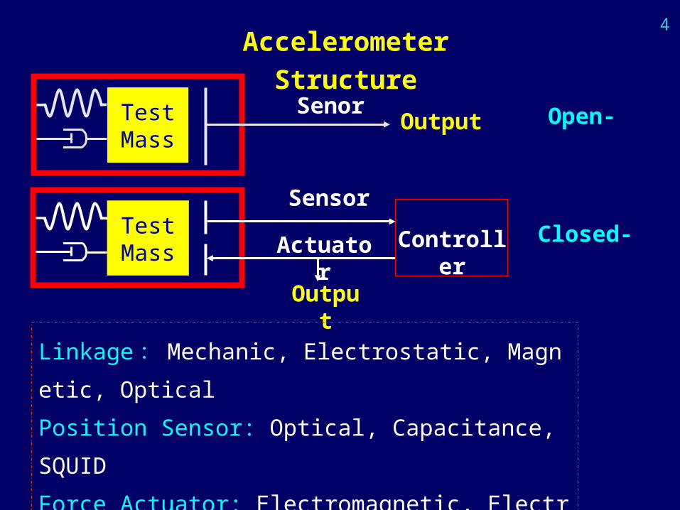
Accelerometer Structure
TestMass
Senor Open-Output
TestMass Actuator Controller Closed-
Output
Sensor
Linkage:Mechanic, Electrostatic, Magnetic, Optical
Position Sensor: Optical, Capacitance, SQUID
Force Actuator: Electromagnetic, Electrostatic, Piezo-
Control Unit: simulative, digital, mixed
5
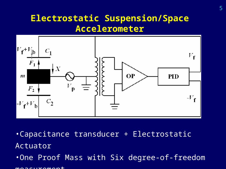
Electrostatic Suspension/Space Accelerometer
•Capacitance transducer + Electrostatic Actuator
•One Proof Mass with Six degree-of-freedom measurement
6
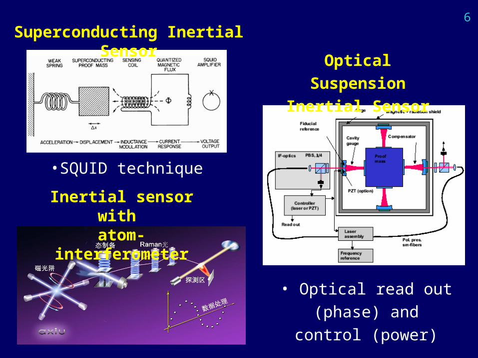
Superconducting Inertial Sensor
•SQUID technique
Optical Suspension
Inertial Sensor
• Optical read out (phase)
and control (power)
Inertial sensor with atom-interferometer
7
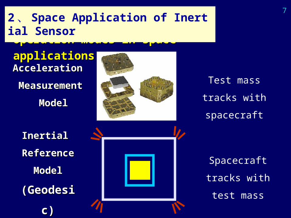
Acceleration Acceleration
MeasurementMeasurement
ModelModel
Inertial Inertial
ReferenceReference
ModelModel
(Geodesic)(Geodesic)
Test mass tracks
with spacecraft
Spacecraft tracks
with test mass
Operation modes in space applicationsOperation modes in space applications
2、 Space Application of Inertial Sensor
8
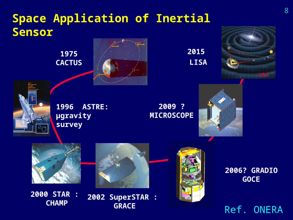
1975 CACTUS
1996 ASTRE: µgravity survey
2000 STAR : CHAMP
2002 SuperSTAR : GRACE
2006? GRADIO GOCE
2009 ?MICROSCOPE
2015 LISA
Ref. ONERA
Space Application of Inertial Sensor
9
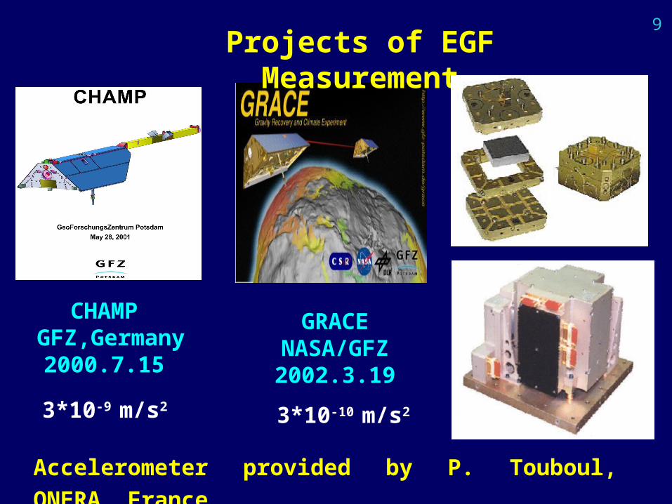
CHAMP GFZ,Germany
2000.7.15
GRACENASA/GFZ
2002.3.19
Projects of EGF Measurement
3*10-9 m/s2 3*10-10 m/s2
Accelerometer provided by P. Touboul, ONERA, France
10
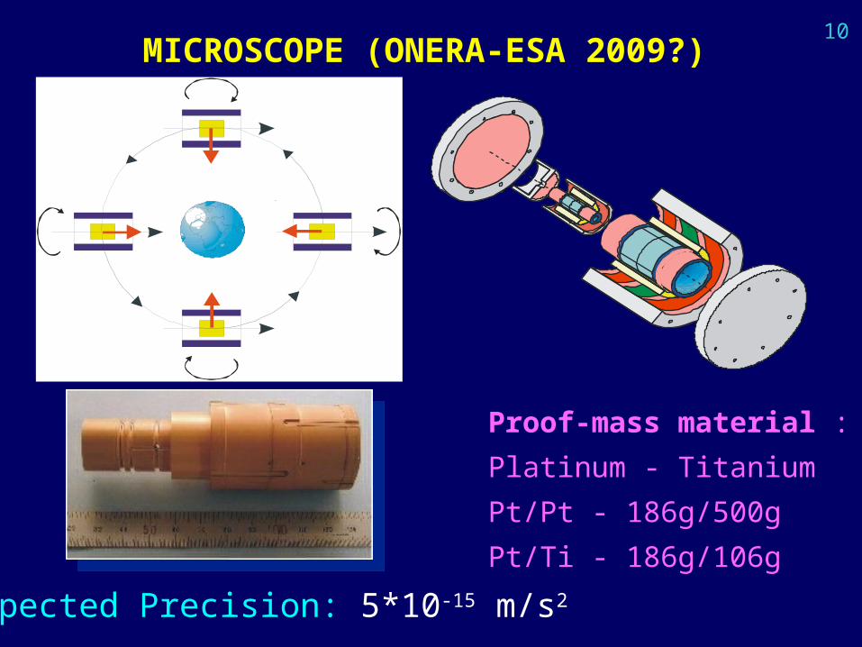
MICROSCOPE (ONERA-ESA 2009?)
Proof-mass material :
Platinum - Titanium
Pt/Pt - 186g/500g
Pt/Ti - 186g/106g
Expected Precision: 5*10-15 m/s2
11
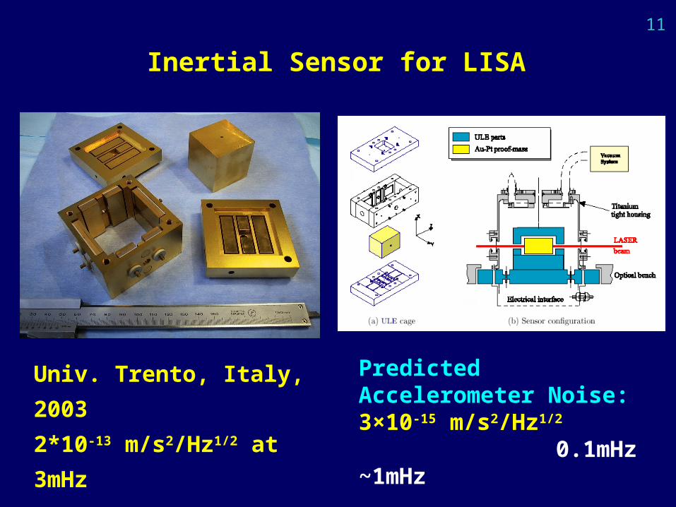
Predicted Accelerometer Noise: 3×10-15 m/s2/Hz1/2
0.1mHz ~1mHz
Inertial Sensor for LISA
Univ. Trento, Italy, 2003
2*10-13 m/s2/Hz1/2 at 3mHz
12
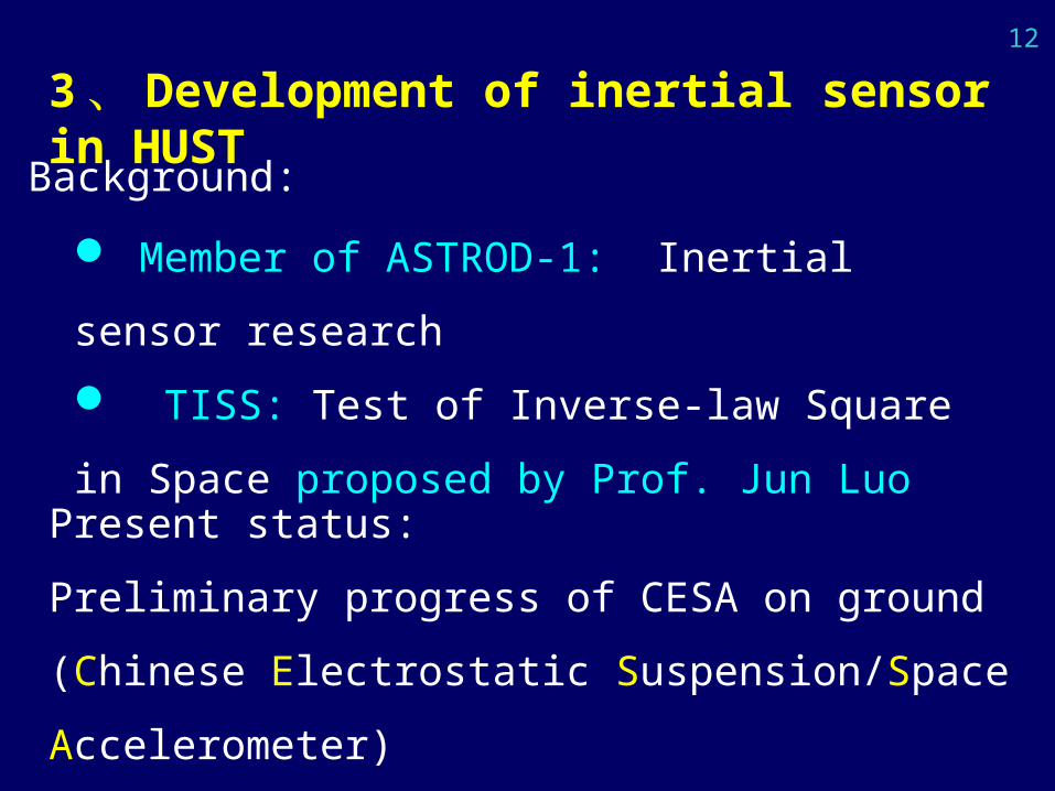
3、 Development of inertial sensor in HUST
Member of ASTROD-1: Inertial sensor research
TISS: Test of Inverse-law Square in Space
proposed by Prof. Jun Luo
Background:
Present status:
Preliminary progress of CESA on ground
(Chinese Electrostatic Suspension/Space Accelerometer)
13
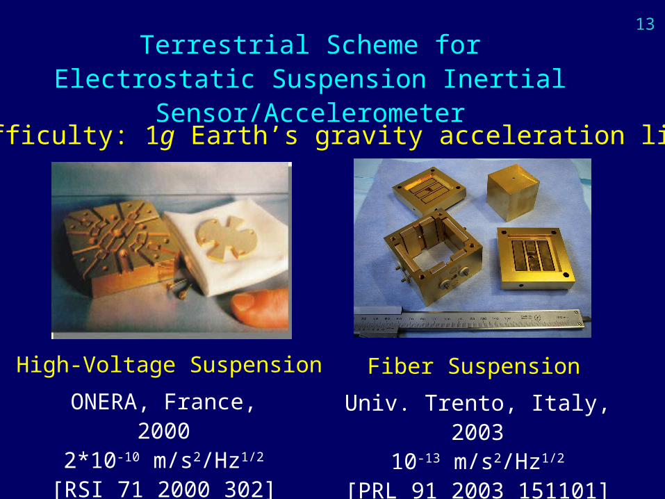
Terrestrial Scheme for Electrostatic Suspension Inertial Sensor/Accelerometer
ONERA, France, 20002*10-10 m/s2/Hz1/2
[RSI 71 2000 302]
Univ. Trento, Italy, 200310-13 m/s2/Hz1/2
[PRL 91 2003 151101]
High-Voltage Suspension Fiber Suspension
Main difficulty: 1g Earth’s gravity acceleration limit
14
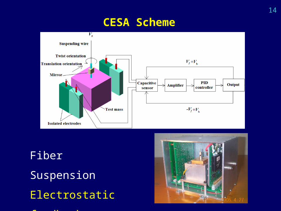
Fiber Suspension
Electrostatic feedback
CESA Scheme
15
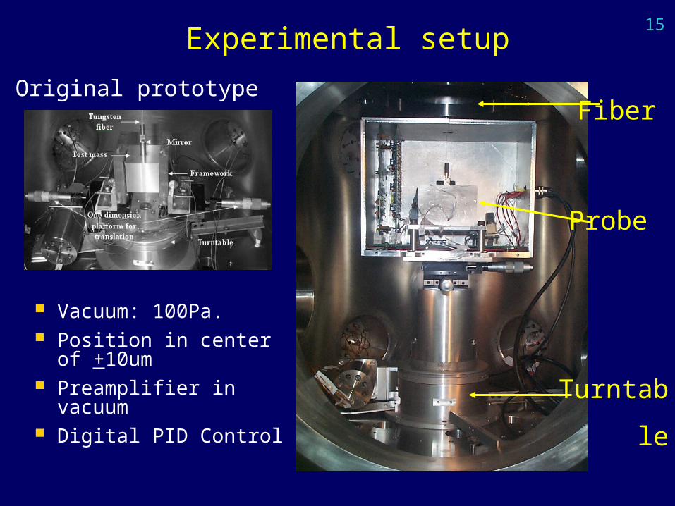
Turntable
Probe
Fiber
Experimental setup
Vacuum: 100Pa. Position in center of
+10um Preamplifier in
vacuum Digital PID Control
Original prototype
17
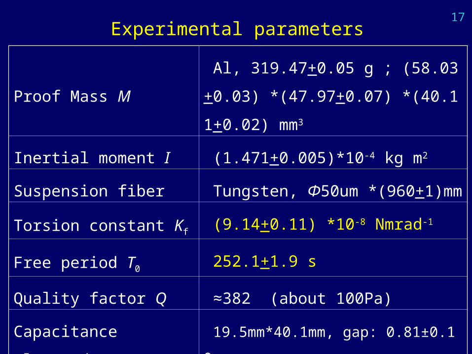
Experimental parameters
Proof Mass M Al, 319.47+0.05 g ; (58.03+0.03) *(47.9
7+0.07) *(40.11+0.02) mm3
Inertial moment I (1.471+0.005)*10-4 kg m2
Suspension fiber Tungsten, Φ50um *(960+1)mm
Torsion constant Kf (9.14+0.11) *10-8 Nmrad-1
Free period T0 252.1+1.9 s
Quality factor Q ≈382 (about 100Pa)
Capacitance electrode 19.5mm*40.1mm, gap: 0.81±0.10 mm;
Capacitance in balance C0 8.7+1.1 pF
18
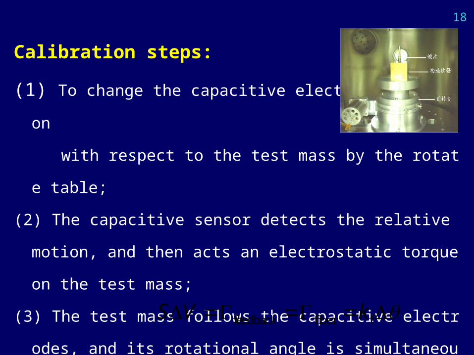
Calibration steps:
(1) To change the capacitive electrodes position
with respect to the test mass by the rotate table;
(2) The capacitive sensor detects the relative motion, and then acts an e
lectrostatic torque on the test mass;
(3) The test mass follows the capacitive electrodes, and its rotational a
ngle is simultaneously monitored by an optical level.
* In this case, the electrostatic torque is equal to the fibre
restoring one. feedback fiber fS V k
19
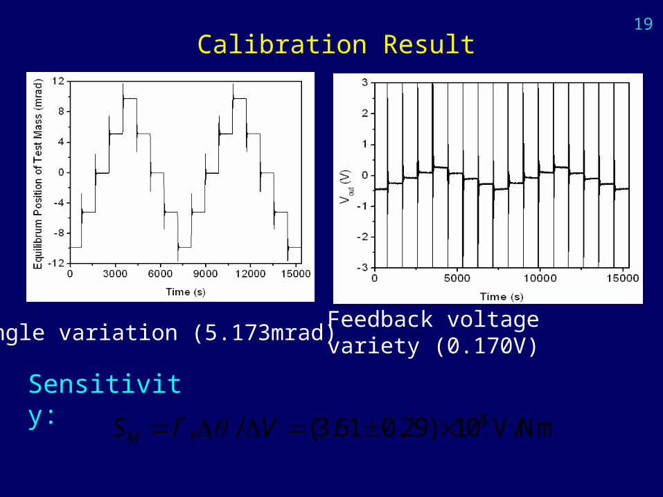
Sensitivity:
Calibration Result
Feedback voltage variety (0.170V)Angle variation (5.173mrad)
8f / (3.61 0.29) 10 V/NmMS Γ V
20
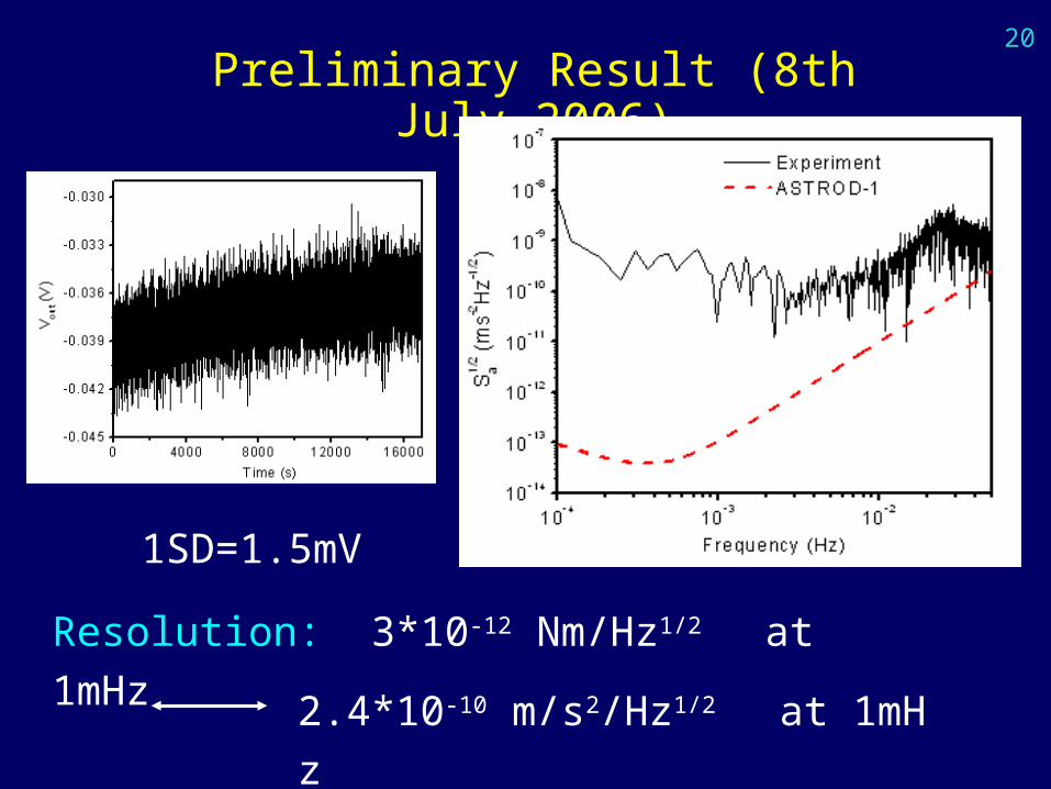
Preliminary Result (8th July,2006)
Resolution: 3*10-12 Nm/Hz1/2 at 1mHz
2.4*10-10 m/s2/Hz1/2 at 1mHz
1SD=1.5mV
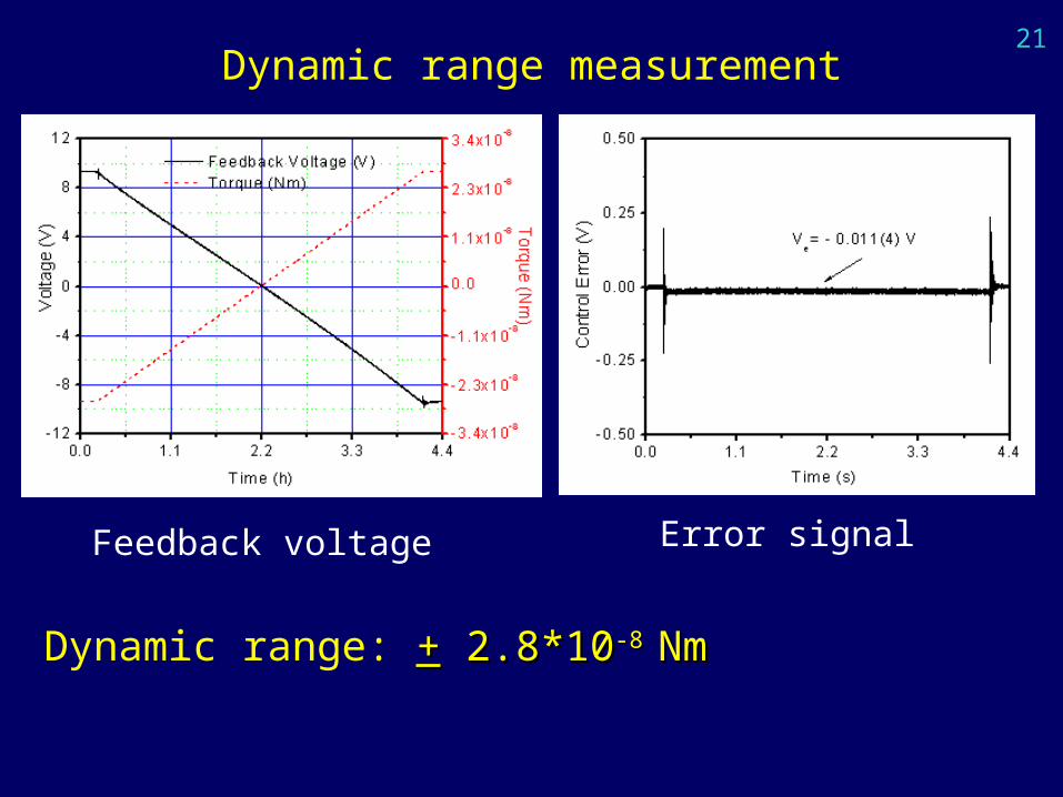
21
Dynamic range: ++ 2.8*10 2.8*10-8 -8 NmNm
Dynamic range measurement
Feedback voltage Error signal
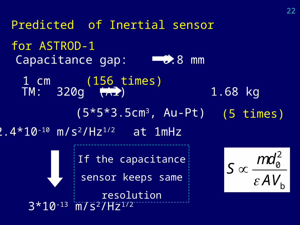
22
Predicted of Inertial sensor for ASTROD-1
Capacitance gap: 0.8 mm 1 cm (156 times)
TM: 320g (Al) 1.68 kg (5*5*3.5cm3, Au-Pt)
3*10-13 m/s2/Hz1/2
(5 times)
2.4*10-10 m/s2/Hz1/2 at 1mHz
If the capacitance sensor
keeps same resolution
20
b
mdS
AV
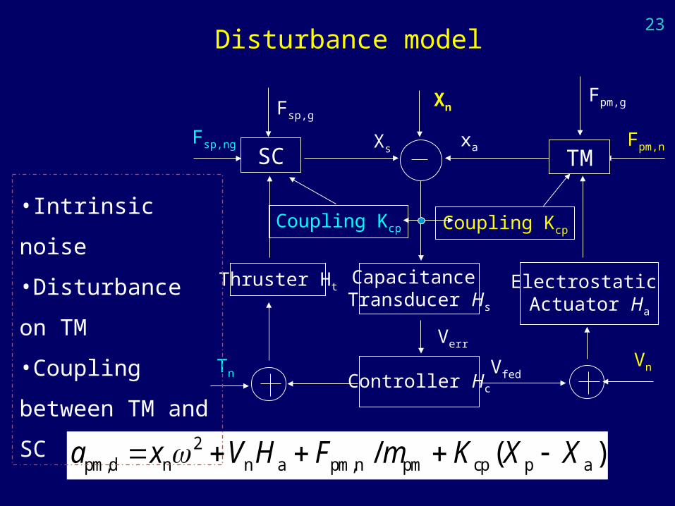
23
Disturbance model
2pm,d n n a pm,n pm cp p a/ ( )a x V H F m K X X
Fsp,g
Fsp,ng Xsxa
Fpm,g
Fpm,n
Capacitance Transducer Hs
Controller Hc
Electrostatic Actuator Ha
Coupling Kcp
VfedVn
Coupling Kcp
Xn
Verr
TMSC
Thruster Ht
Tn
•Intrinsic noise
•Disturbance on TM
•Coupling between
TM and SC
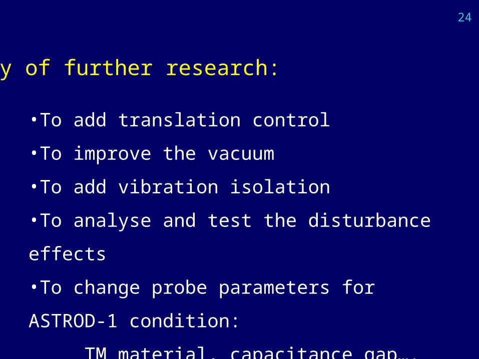
24
Key of further research:
•To add translation control
•To improve the vacuum
•To add vibration isolation
•To analyse and test the disturbance effects
•To change probe parameters for ASTROD-1
condition:
TM material, capacitance gap….
25
•Inertial Sensor/Accelerometer is one of key technologies
for space fundamental experiments. It will be developed
with the requirement of space mission, and inversely then
it will push the space mission.
•Electrostatic suspension/space accelerometer has been
studied for over 30 years, and succeed to be used in space.
•CESA should be studied step by step, too much
disturbances need be analyzed, tested, and suppressed.
4. Summary
26
Thank you very much!