Embed Size (px)
Citation preview
OPERATING INSTRUCTIONS
INFRARED WIRELESS SPEAKER IR-820SP
Thank you for purchasing TOA’s Infrared Wireless Speaker. Please carefully follow the instructions in this manual to ensure long, trouble-free use of your equipment.

2
TABLE OF CONTENTS
1. IMPORTANT SAFETY INSTRUCTIONS ........................................... 3
2. SAFETY PRECAUTIONS ............................................................................. 4
3. GENERAL DESCRIPTION .......................................................................... 5
4. FEATURES ............................................................................................................ 5
5. NOMENCLATURE AND DIMENSIONS .............................................. 6
6. SYSTEM CONFIGURATION EXAMPLE ............................................. 7
7. INSTALLATION PRECAUTIONS ............................................................. 87.1. Installation Position ................................................................................................ 87.2. Distance Between the Infrared Wireless Microphone and IR-820SP ..................... 87.3. Radio Noise ........................................................................................................... 97.4. Connection to IR-802T ......................................................................................... 97.5. Sunlight and Fluorescent Lighting ......................................................................... 9
8. MOUNTING HARDWARE INSTALLATION .................................... 10
9. WIRING .................................................................................................................. 14
10. SPEAKER INSTALLATION .................................................................... 15
11. REMOVING THE IR-820SP FOR MAINTENANCE .................... 17
12. INPUT OVERLOAD PROTECTION FUNCTION ........................ 18
13. SAFETY AGENCY COMPLIANCE .................................................... 18
14. TROUBLESHOOTING ............................................................................... 18
15. SPECIFICATIONS ........................................................................................ 19Accessories ............................................................................................................... 19Optional product ........................................................................................................ 19

3
1. IMPORTANT SAFETY INSTRUCTIONS
• Read these instructions.
• Keep these instructions.
• Heed all warnings.
• Follow all instructions.
• Do not use this apparatus near water.
• Clean only with dry cloth.
• Do not block any ventilation openings. Install in accordance with the manufacture's instructions.
• Do not install near any heat sources such as radiators, heat registers, stoves, or other apparatus (including amplifi ers) that produce heat.
• Do not defeat the safety purpose of the polarized or grounding-type plug. A polarized plug has two blades with one wider than the other. A grounding type plug has two blades and a
third grounding prong. The wide blade or the third prong are provided for your safety. If the provided plug does not fi t into your outlet, consult an electrician for replacement of the obsolete outlet.
• Protect the power cord from being walked on or pinched particularly at plugs, convenience receptacles, and the point where they exit from the apparatus.
• Only use attachments/accessories specifi ed by the manufacturer.
• Use only with the cart, stand, tripod, bracket, or table specifi ed by the manufacturer, or sold with the apparatus.
When a cart is used, use caution when moving the cart/apparatus combination to avoid injury from tip-over.
• Unplug this apparatus during lightning storms or when unused for long periods of time.
• Refer all servicing to qualifi ed service personnel. Servicing is required when the apparatus has been damaged in any way, such as power-supply cord or plug is damaged, liquid has been spilled or objects have fallen into the apparatus, the apparatus has been exposed to rain or moisture, does not operate normally, or has been dropped.
4
2. SAFETY PRECAUTIONS
• Before installation or use, be sure to carefully read all the instructions in this section for correct and safe operation.
• Be sure to follow all the precautionary instructions in this section, which contain important warnings and/or cautions regarding safety.
• After reading, keep this manual handy for future reference.
Safety Symbol and Message Conventions Safety symbols and messages described below are used in this manual to prevent bodily injury and property damage which could result from mishandling. Before operating your product, read this manual fi rst and understand the safety symbols and messages so you are thoroughly aware of the potential safety hazards.
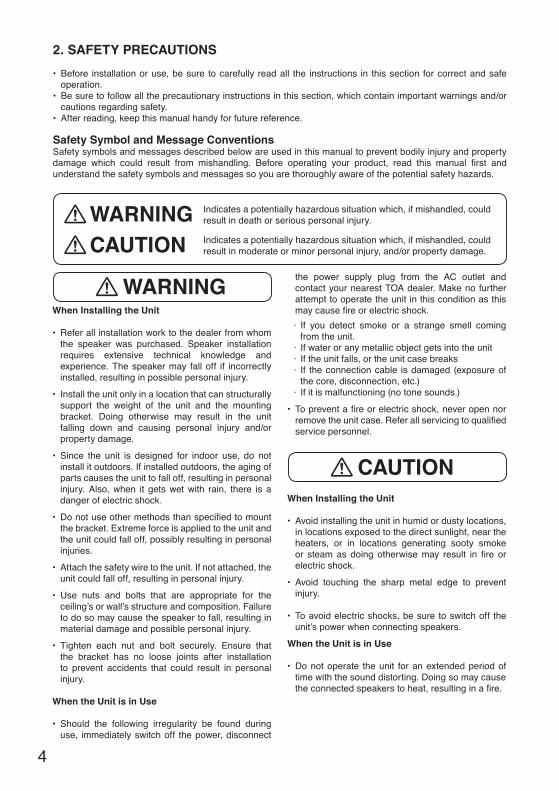
Indicates a potentially hazardous situation which, if mishandled, could result in death or serious personal injury.
Indicates a potentially hazardous situation which, if mishandled, could result in moderate or minor personal injury, and/or property damage.
WARNINGCAUTION
When Installing the Unit
• Refer all installation work to the dealer from whom the speaker was purchased. Speaker installation requires extensive technical knowledge and experience. The speaker may fall off if incorrectly installed, resulting in possible personal injury.
• Install the unit only in a location that can structurally support the weight of the unit and the mounting bracket. Doing otherwise may result in the unit falling down and causing personal injury and/or property damage.
• Since the unit is designed for indoor use, do not install it outdoors. If installed outdoors, the aging of parts causes the unit to fall off, resulting in personal injury. Also, when it gets wet with rain, there is a danger of electric shock.
• Do not use other methods than specifi ed to mount the bracket. Extreme force is applied to the unit and the unit could fall off, possibly resulting in personal injuries.
• Attach the safety wire to the unit. If not attached, the unit could fall off, resulting in personal injury.
• Use nuts and bolts that are appropriate for the ceiling’s or wall’s structure and composition. Failure to do so may cause the speaker to fall, resulting in material damage and possible personal injury.
• Tighten each nut and bolt securely. Ensure that the bracket has no loose joints after installation to prevent accidents that could result in personal injury.
When the Unit is in Use
• Should the following irregularity be found during use, immediately switch off the power, disconnect
the power supply plug from the AC outlet and contact your nearest TOA dealer. Make no further attempt to operate the unit in this condition as this may cause fi re or electric shock.
· If you detect smoke or a strange smell coming from the unit.
· If water or any metallic object gets into the unit · If the unit falls, or the unit case breaks · If the connection cable is damaged (exposure of
the core, disconnection, etc.)· If it is malfunctioning (no tone sounds.)
• To prevent a fi re or electric shock, never open nor remove the unit case. Refer all servicing to qualifi ed service personnel.
When Installing the Unit
• Avoid installing the unit in humid or dusty locations, in locations exposed to the direct sunlight, near the heaters, or in locations generating sooty smoke or steam as doing otherwise may result in fi re or electric shock.
• Avoid touching the sharp metal edge to prevent injury.
• To avoid electric shocks, be sure to switch off the unit’s power when connecting speakers.
When the Unit is in Use
• Do not operate the unit for an extended period of time with the sound distorting. Doing so may cause the connected speakers to heat, resulting in a fi re.
WARNING
CAUTION
5
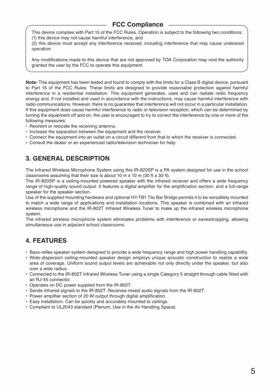
Note: This equipment has been tested and found to comply with the limits for a Class B digital device, pursuant to Part 15 of the FCC Rules. These limits are designed to provide reasonable protection against harmful interference in a residential installation. This equipment generates, uses and can radiate radio frequency energy and, if not installed and used in accordance with the instructions, may cause harmful interference with radio communications. However, there is no guarantee that interference will not occur in a particular installation. If this equipment does cause harmful interference to radio or television reception, which can be determined by turning the equipment off and on, the user is encouraged to try to correct the interference by one or more of the following measures:• Reorient or relocate the receiving antenna.• Increase the separation between the equipment and the receiver.• Connect the equipment into an outlet on a circuit different from that to which the receiver is connected.• Consult the dealer or an experienced radio/television technician for help.
3. GENERAL DESCRIPTION
The Infrared Wireless Microphone System using this IR-820SP is a PA system designed for use in the school classrooms assuming that their size is about 10 m x 10 m (30 ft x 30 ft).The IR-820SP is a ceiling-mounted powered speaker with the infrared receiver and offers a wide frequency range of high-quality sound output. It features a digital amplifi er for the amplifi cation section, and a full-range speaker for the speaker section.Use of the supplied mounting hardware and optional HY-TB1 Tile Bar Bridge permits it to be versatilely mounted to match a wide range of applications and installation locations. This speaker is combined with an infrared wireless microphone and the IR-802T Infrared Wireless Tuner to make up the infrared wireless microphone system. The infrared wireless microphone system eliminates problems with interference or eavesdropping, allowing simultaneous use in adjacent school classrooms.
4. FEATURES
• Bass-refl ex speaker system designed to provide a wide frequency range and high power handling capability.• Wide-dispersion ceiling-mounted speaker design employs unique acoustic construction to realize a wide
area of coverage. Uniform sound output levels are achievable not only directly under the speaker, but also over a wide radius.
• Connected to the IR-802T Infrared Wireless Tuner using a single Category 5 straight through cable fi tted with an RJ-45 connector.
• Operates on DC power supplied from the IR-802T.• Sends infrared signals to the IR-802T. Receives mixed audio signals from the IR-802T. • Power amplifi er section of 20 W output through digital amplifi cation.• Easy installation. Can be quickly and accurately mounted to ceilings.• Compliant to UL2043 standard (Plenum, Use in the Air Handling Space).
This device complies with Part 15 of the FCC Rules. Operation is subject to the following two conditions: (1) this device may not cause harmful interference, and (2) this device must accept any interference received, including interference that may cause undesired operation. Any modifi cations made to this device that are not approved by TOA Corporation may void the authority granted the user by the FCC to operate this equipment.
FCC Compliance

6
5. NOMENCLATURE AND DIMENSIONS
App
rox.
600
(23
.62)
[Ceiling mounting]
[Front] [Side]
[Rear]
[Trim ring (accessory)] [Ceiling reinforcement ring (accessory)]
Safety wire hook
Choke bracket
Connector cover
Front grille
Power indicator
Infrared filter
Unit: mm (inches)
Safety wire (accessory)
70.5 (2.78)
205 (8.07)
ø32
0 (ø
12.6
)
ø35
0 (ø
13.7
8)
30 (
1.18
)
ø235 (ø9.25)
ø300 (ø11.81)
Ceiling reinforcement ring(accessory)
Trim ring (accessory)
Max
. 37
(1.4
6)
Max
.131
(5.
16)
ø300 (ø11.81) (Mounting hole)
ø366.5 (ø14.43)
9.5 (ø0.38)
47.3 (1.86)
65 (2.56)
1.2 (0.05)
1.2 (0.05)
7
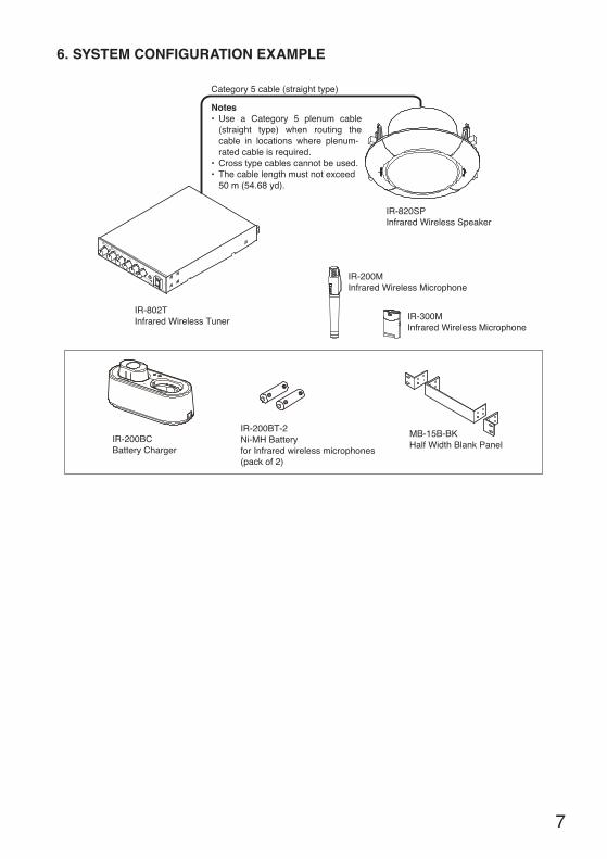
6. SYSTEM CONFIGURATION EXAMPLE
IR-200BCBattery Charger
IR-820SPInfrared Wireless Speaker
IR-802TInfrared Wireless Tuner
MB-15B-BKHalf Width Blank Panel
IR-200BT-2 Ni-MH Battery for Infrared wireless microphones (pack of 2)
IR-200MInfrared Wireless Microphone
IR-300MInfrared Wireless Microphone
Use a Category 5 plenum cable (straight type) when routing the cable in locations where plenum-rated cable is required.Cross type cables cannot be used.The cable length must not exceed 50 m (54.68 yd).
Notes
Category 5 cable (straight type)

8
7. INSTALLATION PRECAUTIONS
Because the infrared wireless microphone and the IR-820SP have their own directivity for infrared transmission and reception, take care that they are installed and operated under stable communication conditions.
7.1. Installation Position
• Install the IR-820SP in the ceiling in the center of the room whose size should not exceed 10 m x 10 m (30 ft x 30 ft) with ceiling height of 2.5 – 3 m (8.2 – 9.84 ft) so that the Infrared wireless microphone can be used everywhere throughout the room.
• The infrared beam can be blocked by a human body or other objects. To avoid this, install the IR-820SP in the way that it can be viewed from the infrared wireless microphone.
Note In the fi gure at right, the microphone directly facing
the IR-820SP can be used because no obstacle exists between them.
However, when a talker turns his or her back on the IR-820SP, signal reception from the microphone is interrupted because the human body acts as obstacle.
7.2. Distance Between the Infrared Wireless Microphone and IR-820SPMalfunctions or noise could result from the infrared wireless microphone and the IR-820SP being too close to each other. Keep the infrared wireless microphone at least 2 m (6.56 ft) away from the IR-820SP.
2.5
– 3
m(8
.2 –
9.8
4 ft)
About 10 m
(30 ft) max.
About 10 m (30 ft) max.
GoodNG

9
7.3. Radio Noise
Do not install the IR-820SP and cable close to devices that can generate radio noise, such as: inverter-powered equipment (fl uorescent lights, air-conditioners, etc.), dimmers, digital equipment, PCs and other computer equipment.
7.4. Connection to IR-802T
Be sure to connect the connection cable from the IR-820SP to the "TO IR-820SP" terminal on the IR-802T’s rear panel. For further details of the connection, refer to Step 3 on p. 14 .
7.5. Sunlight and Fluorescent Lighting
System malfunctions or noise could result from installing the IR-820SP in locations exposed to sunlight, fl uorescent lighting or other infrared generating sources. When installing the IR-820SP, make the following arrangements so that it is not exposed to infrared sources:
7.5.1. Avoid sunlight
• To prevent the IR-820SP from being directly exposed to sunlight, block the sunlight using curtains or window shades.
• When mounting the IR-820SP to a ceiling, keep it at least 2 m (6.56 ft) away from the window.
7.5.2. Install away from fluorescent lighting
When installing the IR-820SP, keep it at least 50 cm (1.64 ft) away from the fl uorescent lighting.
7.5.3. Avoid installing close to other infrared sources shown below
• Lighting device• Liquid crystal projectors, overhead projectors and incandescent lights• Plasma displays• Remote control units, infrared LAN and other infrared devices
Fluorescent lightingIR-820SP
Over 50 cm(1.64 ft) Over 2 m (6.56 ft)
Sunlight
IR-802T
DC24V
DC24V

10
8. MOUNTING HARDWARE INSTALLATION
Before Installing the IR-820SPDetermine the most appropriate method for the ceiling structure. Be sure to use an optional HY-TB1 Tile Bar Bridge in combination with the supplied ceiling reinforcement ring.
[Installation view on Drop Ceilings]
Because the bridge rails are 603 mm (23.74”) in length, be sure to match them to the ceiling tile size during installation.
[Installation view on Dry Wall Ceilings]
Set the bridge rails so that both ends fi t securely into the T-grids, even if the ceiling tile accidentally falls off.WARNING
Only install the Tile Bar Bridge on ceiling frames that can structurally support the weight of the speaker.WARNING
Ceiling tileT-grid
Bridge railHY-TB1 (optional)
Ceiling reinforcement ring (accessory)
Reinforcement ring mounting screw
Tie-plate mounting screw
Tie-plate (preinstalled on Bridge rail)
Ceiling panel
Reinforcement ring mounting screw
HY-TB1 (optional)Bridge rail
Ceiling reinforcement ring (accessory)
Ceiling frame
Tie-plate mounting screw
Tie-plate (preinstalled on Bridge rail)

11
Step 1. Cut a φ300 mm (11.81”) hole in the ceiling.Use the supplied paper pattern to position and trace the hole.
Step 2. Install the HY-TB1 in the ceiling.Loosen the two reinforcement ring mounting screws in each tie-plate to the point that they do not fall out of their holes.
[For Drop Ceiling]
• Mounting to 2-foot tilesAlign the two bridge rails as shown in the fi gure at right.
• Mounting to 600 mm tilesAlign the two bridge rails diagonally at an angle of 10° – 15°.
Ceiling panel or ceiling tile
ø300 ± 5 mm (11.81 ± 0.2")
Tie-plate mounting screw
Reinforcement ring mounting screws(Leave these screws loose.)
Bridge rail
HY-TB1(optional)
Tie-plate
T-grid
2-foot tile
HY-TB1 (optional)
T-grid
600 mm tile
10º – 15º
HY-TB1 (optional)

12
Step 3. Place the supplied reinforcement ring on the ceiling panel.
Fold the reinforcement ring in half* and insert it through the mounting hole in the ceiling panel.
* The reinforcement ring is too large to be inserted into the mounting hole unless folded.
Then open it with its tabs facing up. Place the ring on the ceiling panel aligning it with the mounting hole.
Step 4. Attach the ceiling reinforcement ring to each tie-plate using 2 reinforcement ring mounting screws.
If the ceiling reinforcement ring does not line up accurately with the ceiling mounting hole, adjust its position by either loosening the tie-plate mounting screws and sliding the tie-plate into correct position, or by shifting the tie-plate mounting screws to the appropriate holes in the Tile Bridge rails.
The ceiling reinforcement ring can be moved in the direction indicated by the arrows.
Note Be sure to tighten the tie-plate mounting screws after completing the adjustment.
Mounting hole
Ceiling reinforcement ring (accessory)
Reinforcement ring placed on the ceiling panel
These tabs must face upward, away from the hole.
Ceiling reinforcement ring
Reinforcement ring mounting screw
Tie-plate
Fit closely to the back surfaceof the ceiling panel.
1
2
Ceiling reinforcement ring
Tie-plate mounting screw
Tie-plate

13
Step 5. Attach the supplied trim ring to the IR-820SP.
Step 6. Attach the supplied safety wire to prevent the IR-820SP from accidentally falling. To attach, tie one end of the safety wire around the speaker’s safety wire hook, and tie its snap ring around solid structure (pipe, building frame, etc.).
Solid structure (pipe, building frame, etc.)
Safety wire (accessory)
Ceiling panel
IR-820SP
HY-TB1 (optional)
Trim ring (accessory)
Safety wire hook
Ceiling frame
Safety wire (accessory)
56
6
5

14
9. WIRING
Step 1. Loosen 2 mounting screws first, then gradually loosen 2 bracket screws alternately to slide the choke brackets outward.
Step 2. Loosen 2 connector cover mounting screws, then open the connector cover by sliding it.
Step 3. Run the speaker cable through the gap in the choke bracket, then connect its RJ-45 connector to the IR-802T connection terminal.
Notes• Use a Category 5 plenum cable (straight type)
when routing the cable in locations where plenum-rated cable is required.
• Cross type cables cannot be used.• The cable length must not exceed 50 m (54.68
yd).• Be sure to connect the connection cable from
the IR-820SP to the "TO IR-820SP" terminal on the IR-802T's rear panel.
Never short-circuit the connector nor connect it to the LAN terminal of other device, as this could cause the unit failure.
Step 4. Close the connector cover by sliding it, then retighten the 2 loosened screws to secure it.
Step 5. Gradually tighten 2 bracket screws alternately to slide the choke brackets inward until the cable is clamped. Then, retighten the 2 loosened mounting screws.
Choke bracket
Connector cover
2
Mounting screw
Bracket screw
1
3 IR-802T connection terminal
To the IR-802T's "TO IR-820SP" terminal
5
4
To avoid electric shocks, be sure to switch off the IR-802T Infrared Wireless Tuner’s power when connecting the IR-820SP.
CAUTION
15
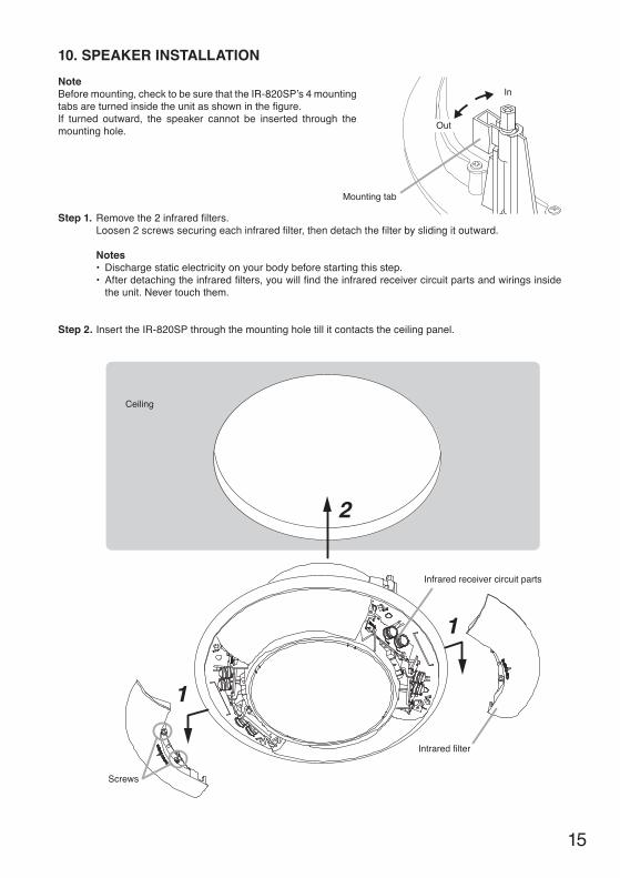
10. SPEAKER INSTALLATION
NoteBefore mounting, check to be sure that the IR-820SP’s 4 mounting tabs are turned inside the unit as shown in the fi gure. If turned outward, the speaker cannot be inserted through the mounting hole.
Step 1. Remove the 2 infrared fi lters.Loosen 2 screws securing each infrared fi lter, then detach the fi lter by sliding it outward.
Notes • Discharge static electricity on your body before starting this step.• After detaching the infrared fi lters, you will fi nd the infrared receiver circuit parts and wirings inside
the unit. Never touch them.
Step 2. Insert the IR-820SP through the mounting hole till it contacts the ceiling panel.
In
Out
Mounting tab
Intrared filter
Screws
Infrared receiver circuit parts
Ceiling
1
1
2

16
Step 3. Rotate and tighten the 4 mounting tab axis screws on the unit clockwise to their full stop in order to grip the ceiling panel with the mounting tabs.
Step 4. Replace the detached 2 infrared fi lters.Replace each infrared fi lter by sliding it inward, then secure the fi lter with 2 screws.
Screws
4
3
4
Mounting tab axis screw
Use an electric screwdriver to tighten.(Tightening torque: 0.58 – 0.98 N·mor 6 – 10 kgf·cm)
Mounting tab

17
11. REMOVING THE IR-820SP FOR MAINTENANCE
Step 1. Remove the 2 infrared fi lters.Loosen 2 screws securing each infrared fi lter, then detach the fi lter by sliding it outward.
Notes • Discharge static electricity on your body before starting this step.• After detaching the infrared fi lters, you will fi nd the infrared receiver circuit parts and wirings inside
the unit. Never touch them.
Step 2. Rotate the 4 mounting tab axis screws counterclockwise. The mounting tabs rise as the screws turn, allowing the speaker to be removed.
Notes• When loosening the mounting tab axis screws,
support the IR-820SP by hand to prevent it from falling.
• Be sure to set the screwdriver’s torque for under 0.58 N·m (6 kgf·cm.)
Failure to do so may cause the screw cap and the mounting tab to fall off on the rear of ceiling panel.
Intrared filter
Screws
Infrared receiver circuit parts
Screws
Mounting tab axis screw
Use an electric screwdriver to detach.
Mounting tab
Screw cap
Counterclockwise

18
12. INPUT OVERLOAD PROTECTION FUNCTION
The IR-820SP features an internal input overload protection circuitry. If an extremely high input level is fed to the unit, the protection circuitry automatically cuts off the signal to the speaker element.
NoteThis protection circuitry does not completely protect the unit against extremely high input power levels. Depending on the type or duration of excessive power input, the protection circuitry might not operate, resulting in damage to the speaker element. Also, if an excessive power input continues for a long period of time, the circuitry may not be capable of resetting to its original condition. Use the system with care so that an excessive power input is not applied to the IR-820SP.
13. SAFETY AGENCY COMPLIANCE
This product is for indoor use only.
Products are suitable for use in general (non-fi re alarm) signaling service in conjunction with compatible Listed audio equipment, the combination of which is intended to be installed in accordance with the applicable requirements of the National Electrical Code (NEC) and the local authority having jurisdiction.Fire Test for Heat and Visible Smoke Release for Discrete Products and their Accessories Installed in Air-Handling Spaces (1998) - NFPA 70 National Electrical Code (NEC) 2002, Article 300-22 (c) and NFPA 90A Installation of air-conditioning and ventilation systems, section 2-3.10.1 (a) exception 3.
14. TROUBLESHOOTING
Symptom Cause and Points to Check RemedyThe power indicator does not light when the power switch is turned on.
The connection cable to IR-802T is possibly failed.
Confi rm correctness of the connection to IR-802T and connection cable. If faulty is found, connect correctly or replace the cable with appropriate one.
No sound outputs. The connection cable to IR-802T is possibly failed.
Confi rm correctness of the connection to IR-802T and connection cable. If faulty is found, connect correctly or replace the cable with appropriate one.
Noise or strange (i.e. muddy) sound is heard.
IR-820SP is installed in close proximity to a device generating radio noise or infrared light.
Set the speaker properly, referring to "7.5. Sunlight and Fluorescent Lighting" (Refer to p. 9 ) for the infrared wireless speaker.
Short transmission distance.
IR-820SP is not properly installed. Install the infrared wireless speaker properly.
Acoustic feedback occurs.
The microphone head is covered with your hand(s).
Do not cover the microphone head with your hand(s).
The IR-802T’s MID level of the equalizer controls is set relatively high.
Decrease the MID level of the equalizer controls.

19
15. SPECIFICATIONS
Power Source 24 V DC (supplied from IR-802T)Power Consumption 4.4 W (based on UL standard)Rated Output 20 WFrequency Response 100 Hz – 20 kHz (–10 dB) at installation in 1/2 free sound fi eld
(Measured by installing the unit in the center of a ceiling.)Amplifi cation System Class DDistortion 5% or less (rated output)Speaker Component 12 cm (5") cone-typeInfrared Wireless ReceiverWavelength 870 nmCarrier Frequency Teacher (Channel A): 3.100 MHz
Student (Channel B): 3.350 MHzReception Angle 360° (Horizontal)
Connection Terminal RJ-45LED Indicator Power (green) x 1UL Code UL60065, UL2043Mounting Hole φ 300 mm (11.81")Usable Cable Category 5 UTPOperating Temperature –10 to 50 ºC (14 to 122 ºF)Operating Humidity 90 %RH or less (no condensation)Finish Enclosure : Steel plate, plating
Baffl e : Fire-resistant ABS resin (resin material grade: UL-94 V-0), white
Punched net : Steel plate, whiteFilter section : Polycarbonate, optical cut fi lter
Dimensions φ320 x 205 (d) mm (φ12.6" x 8.07")Weight 3.4 kg (7.5 lb)
* 0 dB = 1 V
Note: The design and specifi cations are subject to change without notice for improvement.
• Accessories
Safety wire (600 mm or 1.97 ft) .................... 1Ceiling reinforcement ring ............................ 1Paper pattern ................................................ 1Trim ring ........................................................ 1
• Optional product
HY-TB1 Tile Bar Bridge: Use this bridge when mounting the speaker unit to drop ceiling or weak dry wall ceiling.

Traceability Information for Europe (EMC directive 2004/108/EC)
Manufacturer:TOA Corporation7-2-1, Minatojima-Nakamachi, Chuo-ku, Kobe, Hyogo, Japan
Authorized representative:TOA Electronics Europe GmbHSuederstrasse 282, 20537 Hamburg,Germany
URL: http://www.toa.jp/
133-07-312-00