Embed Size (px)
Citation preview
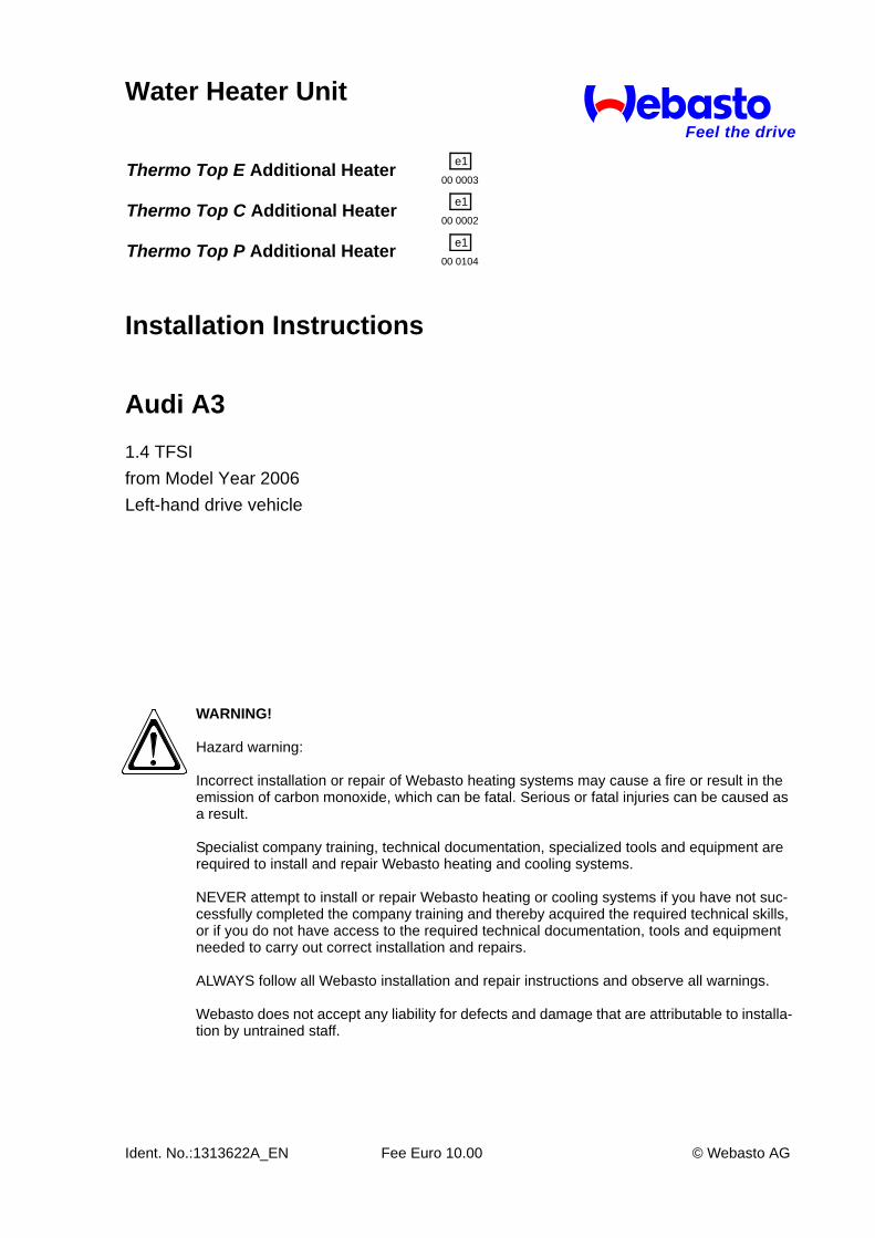
WARNING!
Hazard warning:
Incorrect installation or repair of Webasto heating systems may cause a fire or result in the emission of carbon monoxide, which can be fatal. Serious or fatal injuries can be caused as a result.
Specialist company training, technical documentation, specialized tools and equipment are required to install and repair Webasto heating and cooling systems.
NEVER attempt to install or repair Webasto heating or cooling systems if you have not suc-cessfully completed the company training and thereby acquired the required technical skills, or if you do not have access to the required technical documentation, tools and equipment needed to carry out correct installation and repairs.
ALWAYS follow all Webasto installation and repair instructions and observe all warnings.
Webasto does not accept any liability for defects and damage that are attributable to installa-tion by untrained staff.
Water Heater Unit
Installation Instructions
Ident. No.:1313622A_EN Fee Euro 10.00 © Webasto AG
Audi A31.4 TFSIfrom Model Year 2006Left-hand drive vehicle
Feel the drive
Thermo Top E Additional Heater e100 0003
Thermo Top C Additional Heater e100 0002
Thermo Top P Additional Heater e100 0104
Audi A3
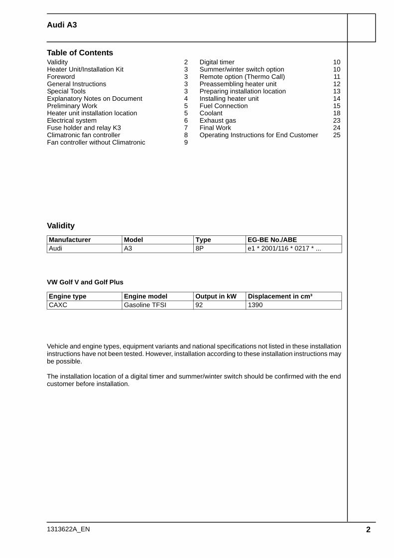
Table of Contents
Validity
VW Golf V and Golf Plus
Vehicle and engine types, equipment variants and national specifications not listed in these installation instructions have not been tested. However, installation according to these installation instructions may be possible.
The installation location of a digital timer and summer/winter switch should be confirmed with the end customer before installation.
Manufacturer Model Type EG-BE No./ABEAudi A3 8P e1 * 2001/116 * 0217 * ...
Engine type Engine model Output in kW Displacement in cm³CAXC Gasoline TFSI 92 1390
Validity 2Heater Unit/Installation Kit 3Foreword 3General Instructions 3Special Tools 3Explanatory Notes on Document 4Preliminary Work 5Heater unit installation location 5Electrical system 6Fuse holder and relay K3 7Climatronic fan controller 8Fan controller without Climatronic 9
Digital timer 10Summer/winter switch option 10Remote option (Thermo Call) 11Preassembling heater unit 12Preparing installation location 13Installing heater unit 14Fuel Connection 15Coolant 18Exhaust gas 23Final Work 24Operating Instructions for End Customer 25
1313622A_EN 2
Audi A3
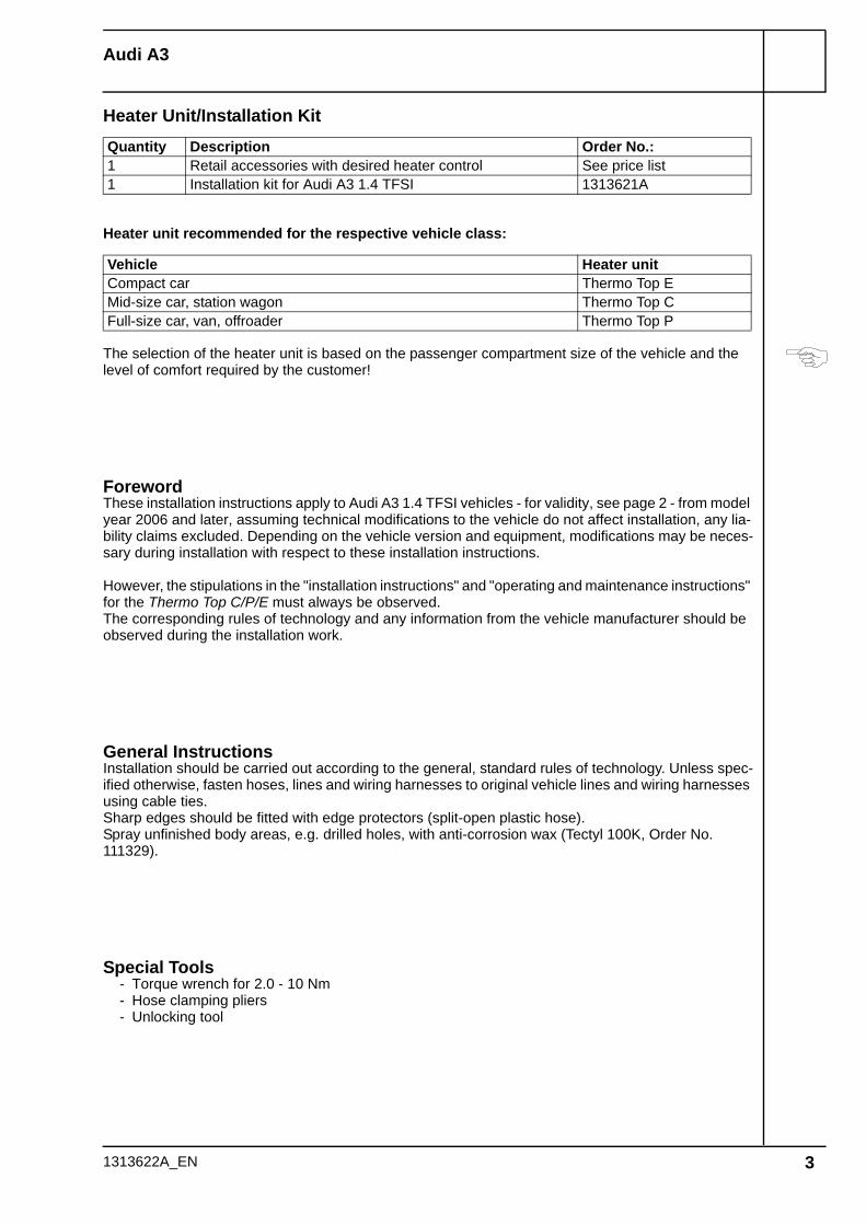
Heater Unit/Installation Kit
Heater unit recommended for the respective vehicle class:
The selection of the heater unit is based on the passenger compartment size of the vehicle and the level of comfort required by the customer!
ForewordThese installation instructions apply to Audi A3 1.4 TFSI vehicles - for validity, see page 2 - from model year 2006 and later, assuming technical modifications to the vehicle do not affect installation, any lia-bility claims excluded. Depending on the vehicle version and equipment, modifications may be neces-sary during installation with respect to these installation instructions.
However, the stipulations in the "installation instructions" and "operating and maintenance instructions" for the Thermo Top C/P/E must always be observed.The corresponding rules of technology and any information from the vehicle manufacturer should be observed during the installation work.
General InstructionsInstallation should be carried out according to the general, standard rules of technology. Unless spec-ified otherwise, fasten hoses, lines and wiring harnesses to original vehicle lines and wiring harnesses using cable ties.Sharp edges should be fitted with edge protectors (split-open plastic hose).Spray unfinished body areas, e.g. drilled holes, with anti-corrosion wax (Tectyl 100K, Order No. 111329).
Special Tools- Torque wrench for 2.0 - 10 Nm- Hose clamping pliers- Unlocking tool
Quantity Description Order No.:1 Retail accessories with desired heater control See price list1 Installation kit for Audi A3 1.4 TFSI 1313621A
Vehicle Heater unitCompact car Thermo Top EMid-size car, station wagon Thermo Top CFull-size car, van, offroader Thermo Top P
1313622A_EN 3
Audi A3
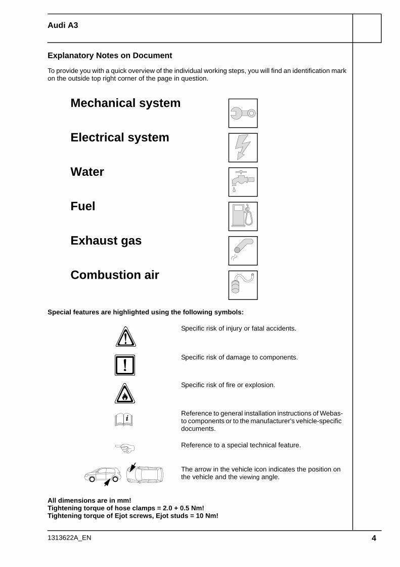
Explanatory Notes on Document
To provide you with a quick overview of the individual working steps, you will find an identification mark on the outside top right corner of the page in question.
1313622A_EN 4
Special features are highlighted using the following symbols:
The arrow in the vehicle icon indicates the position on the vehicle and the viewing angle.
Specific risk of injury or fatal accidents.
Specific risk of damage to components.
Specific risk of fire or explosion.
Reference to general installation instructions of Webas-to components or to the manufacturer's vehicle-specific documents.
Reference to a special technical feature.
All dimensions are in mm!Tightening torque of hose clamps = 2.0 + 0.5 Nm!Tightening torque of Ejot screws, Ejot studs = 10 Nm!
Mechanical system
Electrical system
Water
Fuel
Exhaust gas
Combustion air
Audi A3
Preliminary Work
WARNING!- Open fuel tank cap, ventilate tank.- Close the tank cap again.- Depressurize the cooling system.- Copy the factory number from the original type label to the duplicate type label.- Remove years that do not apply from the duplicate label.- Attach the duplicate label (type label) in the appropriate place.- Disconnect the battery "earth" or "ground" connection.- Remove battery.- Remove the battery carrier.- Remove the engine cover.- Remove the left front wheel- Remove the front section of the left front wheel well trim - Remove the underride protection- Remove the right-hand underbody trim- Remove the rear bench seat- Open the right-hand fuel sender service lid.- Remove the footwell trim on the driver's side- Remove the lower instrument panel trim on the driver's side- Only with Climatronic: Remove the A/C control panel.
Remove page 25 "Operating Instructions for End Customer" and add to the vehicle operating instruc-tions.
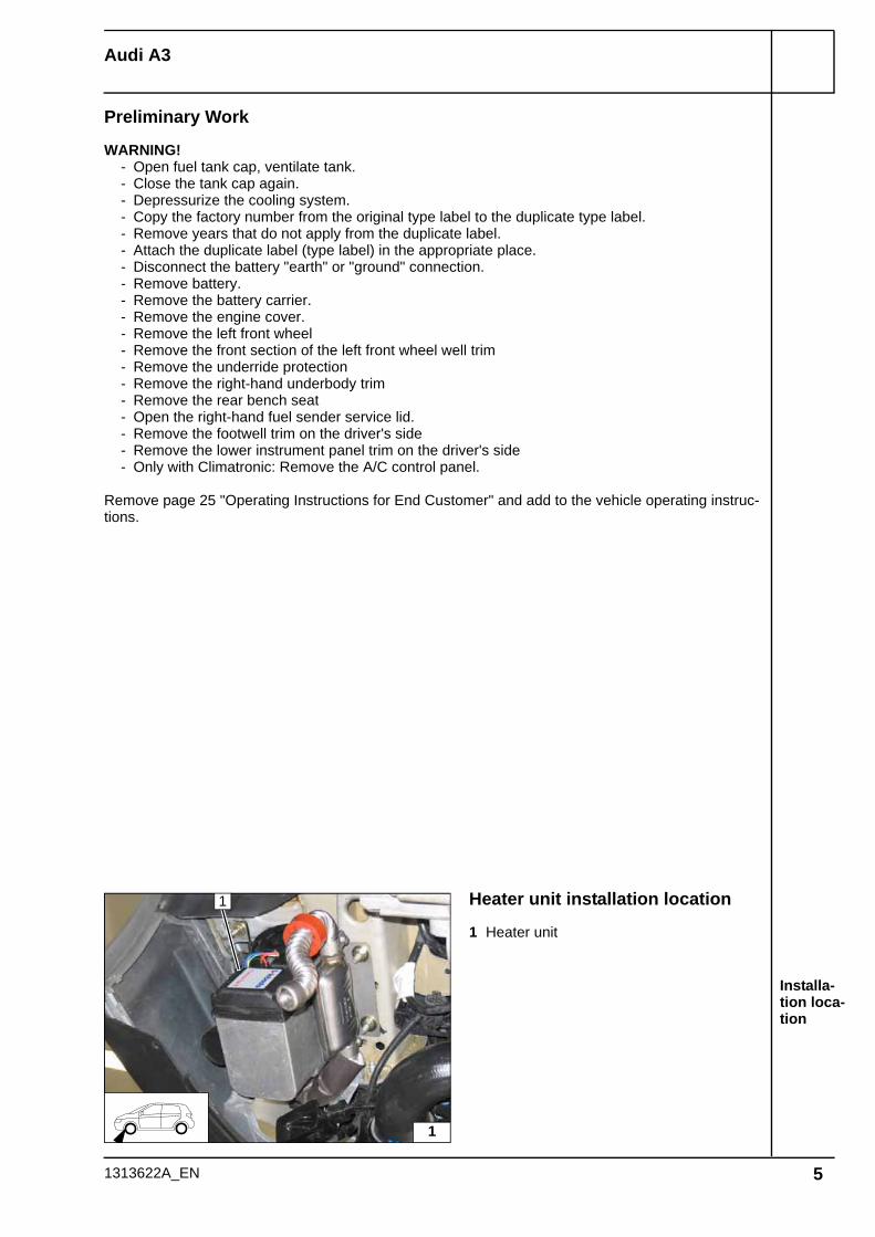
Installa-tion loca-tion
Heater unit installation location
1 Heater unit
1
1
1313622A_EN 5

Audi A3
Wiring har-ness in-stallation diagram
Electrical systemWiring harness routing
Route excess lengths from wiring harness of heater unit 1 in cable duct below battery and se-cure with cable ties.
Wiring harness pass through in engine com-partment
1 Original vehicle wiring harness pass through
Fuse holder, relay K3
Description of installation for K3 relay 1 and fuse carrier 2 on Page 7
Wiring harness pass through of passenger compartment
1 Original vehicle wiring harness pass through
21 1 3
1
5
Do not install the metering pump cable harness until later together with fuel pipe along the original vehicle fuel lines on the under-body
4
2
1
5
1
1313622A_EN 6
Audi A3
Holes for fuse holder and K3 re-lay
Installing fuse holder and K3 re-lay
Installing fuse holder and K3 re-lay
Connect-ing posi-tive and ground wire
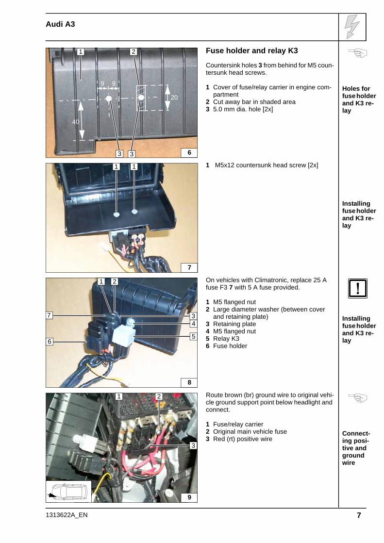
Fuse holder and relay K3
Countersink holes 3 from behind for M5 coun-tersunk head screws.
1 Cover of fuse/relay carrier in engine com-partment
2 Cut away bar in shaded area3 5.0 mm dia. hole [2x]
1 M5x12 countersunk head screw [2x]
On vehicles with Climatronic, replace 25 A fuse F3 7 with 5 A fuse provided.
1 M5 flanged nut2 Large diameter washer (between cover
and retaining plate)3 Retaining plate4 M5 flanged nut5 Relay K36 Fuse holder
Route brown (br) ground wire to original vehi-cle ground support point below headlight and connect.
1 Fuse/relay carrier2 Original main vehicle fuse3 Red (rt) positive wire
1
6
40
9 9
3
20
2
3
7
11
6
2
3
8
74
5
1
21
3
9
1313622A_EN 7
Audi A3
1313622A_EN
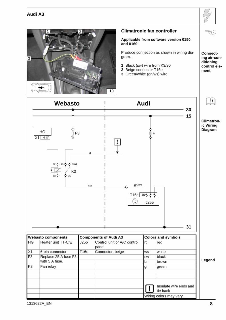
Climatronic fan controller
Applicable from software version 0150 and 0160!
Produce connection as shown in wiring dia-gram.
1 Black (sw) wire from K3/302 Beige connector T16e3 Green/white (gn/ws) wire
Connect-ing air-con-ditioning control ele-ment
Climatron-ic Wiring Diagram
Webasto components Components of Audi A3 Colors and symbols
Legend
HG Heater unit TT-C/E J255 Control unit of A/C control panel
rt red
X1 6-pin connector T16e Connector, beige ws whiteF3 Replace 25 A fuse F3
with 5 A fuse.sw blackbr brown
K3 Fan relay gn green
Insulate wire ends and tie back
Wiring colors may vary.
1 2
3
10
Webasto
31
3015
Audi
F3HG4X1
86
85 30
87a87
K3
sw
!
T16e 16
J255
F
rt
gn/ws
8
Audi A3
1313622A_EN
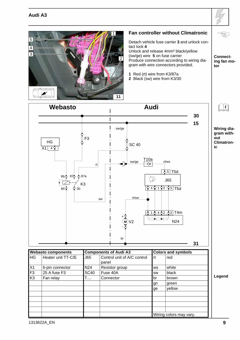
Fan controller without Climatronic
Detach vehicle fuse carrier 3 and unlock con-tact lock 4Unlock and release 4mm² black/yellow (sw/ge) wire 5 on fuse carrierProduce connection according to wiring dia-gram with wire connectors provided.
1 Red (rt) wire from K3/87a2 Black (sw) wire from K3/30
Connect-ing fan mo-tor
Wiring dia-gram with-out Climatron-ic
Webasto components Components of Audi A3 Colors and symbols
Legend
HG Heater unit TT-C/E J65 Control unit of A/C control panel
rt red
X1 6-pin connector N24 Resistor group ws whiteF3 25 A fuse F3 SC40 Fuse 40A sw blackK3 Fan relay T.... Connector br brown
gn greenge yellow
Wiring colors may vary.
15
11
2
43
Webasto
31
3015
Audi
sw/ge
br
rt/sw
rt/ws
sw/ge
T10a
F3HG
4X1
86
85 30
87a87
K3
sw
rt
SC 40
+
-V2M
5 T5d
T5d31 24
J65
T4m34 21
N24
9
Audi A3
Installing digital timer
Installing receiver
Installing antenna
Installing tempera-ture sensor
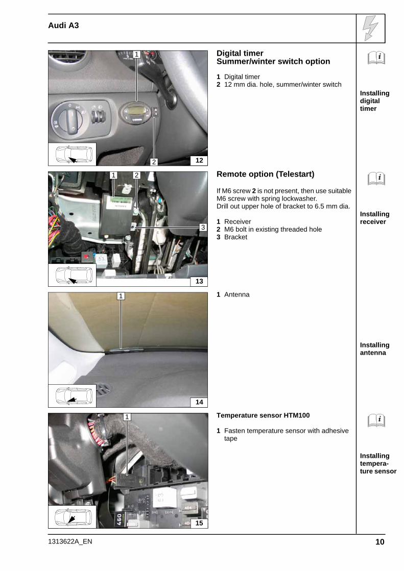
Digital timerSummer/winter switch option
1 Digital timer2 12 mm dia. hole, summer/winter switch
Remote option (Telestart)
If M6 screw 2 is not present, then use suitableM6 screw with spring lockwasher.Drill out upper hole of bracket to 6.5 mm dia.
1 Receiver2 M6 bolt in existing threaded hole3 Bracket
1 Antenna
Temperature sensor HTM100
1 Fasten temperature sensor with adhesive tape
1
122
2
13
1
3
1
14
1
15
1313622A_EN 10
Audi A3
Installing receiver
Installing antenna
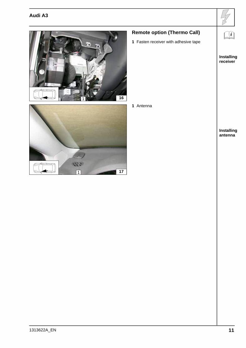
Remote option (Thermo Call)
1 Fasten receiver with adhesive tape
1 Antenna
1 16
1 17
1313622A_EN 11
Audi A3
Cutting combus-tion air pipe to length
Premount-ing heater unit
Premount-ing heater unit
Premount-ing heater unit
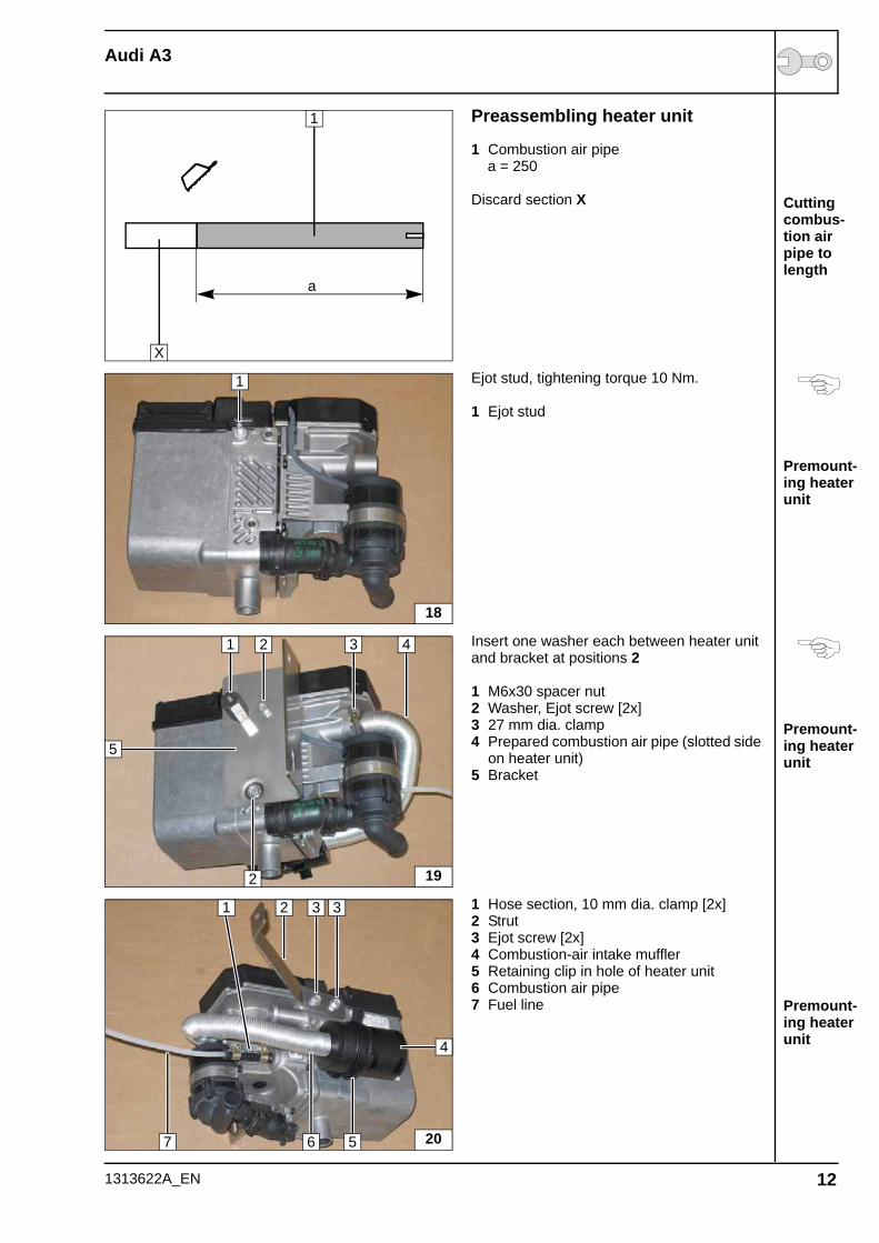
Preassembling heater unit
1 Combustion air pipe a = 250
Discard section X
Ejot stud, tightening torque 10 Nm.
1 Ejot stud
Insert one washer each between heater unit and bracket at positions 2
1 M6x30 spacer nut2 Washer, Ejot screw [2x]3 27 mm dia. clamp4 Prepared combustion air pipe (slotted side
on heater unit)5 Bracket
1 Hose section, 10 mm dia. clamp [2x]2 Strut3 Ejot screw [2x]4 Combustion-air intake muffler5 Retaining clip in hole of heater unit6 Combustion air pipe7 Fuel line
a
1
X
18
1
19
1
5
2 3
2
4
20
2
5
4
3 3
67
1
1313622A_EN 12
Audi A3
Cutting ex-haust pipe to length
Premount-ing ex-haust system
Premount-ing ex-haust system
Preparing installa-tion loca-tion
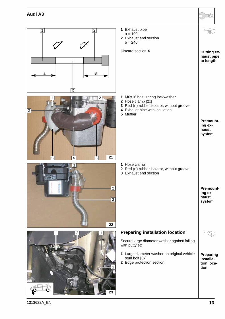
1 Exhaust pipe a = 1902 Exhaust end section b = 240
Discard section X
1 M6x16 bolt, spring lockwasher2 Hose clamp [2x]3 Red (rt) rubber isolator, without groove4 Exhaust pipe with insulation5 Muffler
1 Hose clamp2 Red (rt) rubber isolator, without groove3 Exhaust end section
Preparing installation location
Secure large diameter washer against falling with putty etc.
1 Large diameter washer on original vehicle stud bolt [3x]
2 Edge protection section
a B
1 2
X
215
21
4
2
3
22
3
1
2
23
1
1
12
1313622A_EN 13
Audi A3
Installing heater unit
Aligning exhaust system
Aligning exhaust system
Mounting and rout-ing wiring harness
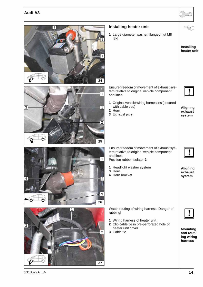
Installing heater unit
1 Large diameter washer, flanged nut M8 [3x]
Ensure freedom of movement of exhaust sys-tem relative to original vehicle component and lines.
1 Original vehicle wiring harnesses (secured with cable ties)
2 Horn3 Exhaust pipe
Ensure freedom of movement of exhaust sys-tem relative to original vehicle component and lines.Position rubber isolator 2.
1 Headlight washer system3 Horn4 Horn bracket
Watch routing of wiring harness. Danger of rubbing!
1 Wiring harness of heater unit 2 Clip cable tie in pre-perforated hole of
heater unit cover3 Cable tie
24
1
1
1
25
2
1
3 1
26
4
1
3
2
27
1
2
3
1313622A_EN 14
Audi A3
Routing to firewall
Routing in coolant reservoir
Routing fuel line and wiring harness of metering pump
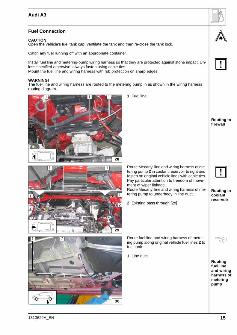
Fuel Connection
CAUTION!Open the vehicle's fuel tank cap, ventilate the tank and then re-close the tank lock.
Catch any fuel running off with an appropriate container.
Install fuel line and metering-pump wiring harness so that they are protected against stone impact. Un-less specified otherwise, always fasten using cable ties.Mount the fuel line and wiring harness with rub protection on sharp edges.
WARNING!The fuel line and wiring harness are routed to the metering pump in as shown in the wiring harness routing diagram.
1 Fuel line
Route Mecanyl line and wiring harness of me-tering pump 2 in coolant reservoir to right and fasten on original vehicle lines with cable ties.Pay particular attention to freedom of move-ment of wiper linkage.Route Mecanyl line and wiring harness of me-tering pump to underbody in line duct.
2 Existing pass through [2x]
Route fuel line and wiring harness of meter-ing pump along original vehicle fuel lines 2 to fuel tank.
1 Line duct
28
1 1 1
29
1 1
22
11
1 2
30
1313622A_EN 15
Audi A3
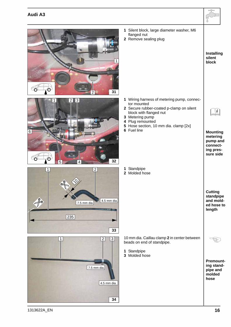
Installing silent block
Mounting metering pump and connect-ing pres-sure side
Cutting standpipe and mold-ed hose to length
Premount-ing stand-pipe and molded hose
1 Silent block, large diameter washer, M6 flanged nut
2 Remove sealing plug
1 Wiring harness of metering pump, connec-tor mounted
2 Secure rubber-coated p-clamp on silent block with flanged nut
3 Metering pump4 Plug remounted5 Hose section, 10 mm dia. clamp [2x]6 Fuel line
1 Standpipe2 Molded hose
10 mm dia. Caillau clamp 2 in center between beads on end of standpipe.
1 Standpipe3 Molded hose
31
1
2
32
1
6
5
2 3
4
1 2
33
235
10
4.5 mm dia.7.5 mm dia.
34
1 2 3
7.5 mm dia.
4.5 mm dia.
1313622A_EN 16
Audi A3
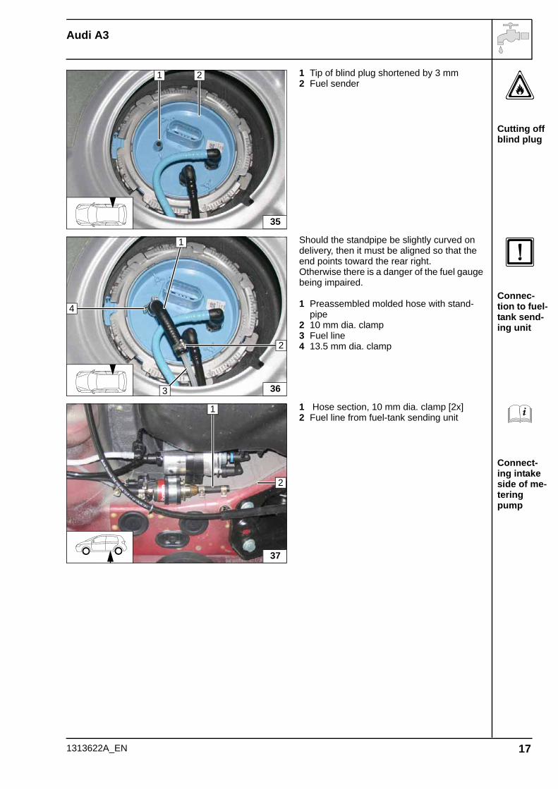
Cutting off blind plug
Connec-tion to fuel-tank send-ing unit
Connect-ing intake side of me-tering pump
1 Tip of blind plug shortened by 3 mm2 Fuel sender
Should the standpipe be slightly curved on delivery, then it must be aligned so that the end points toward the rear right.Otherwise there is a danger of the fuel gauge being impaired.
1 Preassembled molded hose with stand-pipe
2 10 mm dia. clamp3 Fuel line4 13.5 mm dia. clamp
1 Hose section, 10 mm dia. clamp [2x]2 Fuel line from fuel-tank sending unit
1
35
2
36
4
3
2
1
37
2
1
1313622A_EN 17
Audi A3
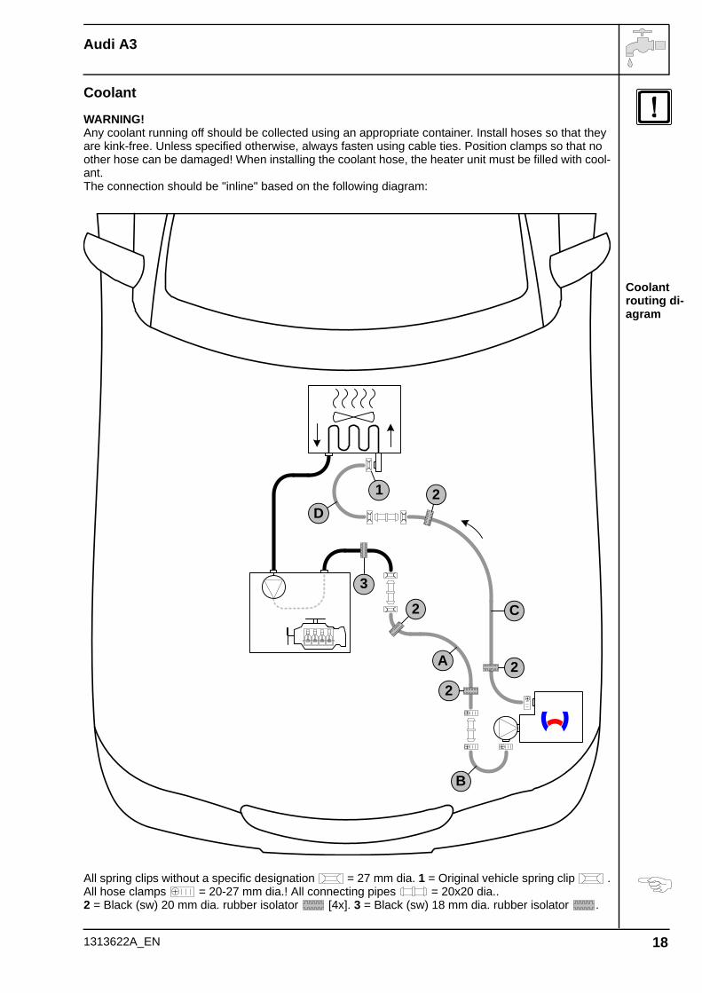
Coolant routing di-agram
Coolant
WARNING!Any coolant running off should be collected using an appropriate container. Install hoses so that they are kink-free. Unless specified otherwise, always fasten using cable ties. Position clamps so that no other hose can be damaged! When installing the coolant hose, the heater unit must be filled with cool-ant.The connection should be "inline" based on the following diagram:
All spring clips without a specific designation = 27 mm dia. 1 = Original vehicle spring clip .All hose clamps = 20-27 mm dia.! All connecting pipes = 20x20 dia..2 = Black (sw) 20 mm dia. rubber isolator [4x]. 3 = Black (sw) 18 mm dia. rubber isolator .
A
C
3
1D
B
2
22
2
1313622A_EN 18
Audi A3
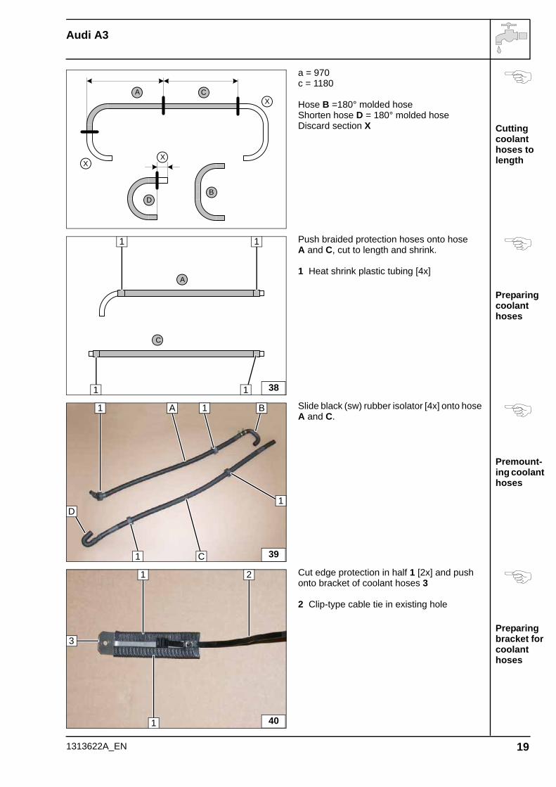
Cutting coolant hoses to length
Preparing coolant hoses
Premount-ing coolant hoses
Preparing bracket for coolant hoses
a = 970c = 1180
Hose B =180° molded hoseShorten hose D = 180° molded hoseDiscard section X
Push braided protection hoses onto hose A and C, cut to length and shrink.
1 Heat shrink plastic tubing [4x]
Slide black (sw) rubber isolator [4x] onto hose A and C.
Cut edge protection in half 1 [2x] and push onto bracket of coolant hoses 3
2 Clip-type cable tie in existing hole
A C
X
X
BD
X
C
A
1
1
1 38
1
A
C
1 B
1 39
1
1
D
1
1
3
2
40
1313622A_EN 19
Audi A3
Installing bracket for coolant hoses
Cutting point
Pushing on rubber iso-lator
Connect-ing engine outlet
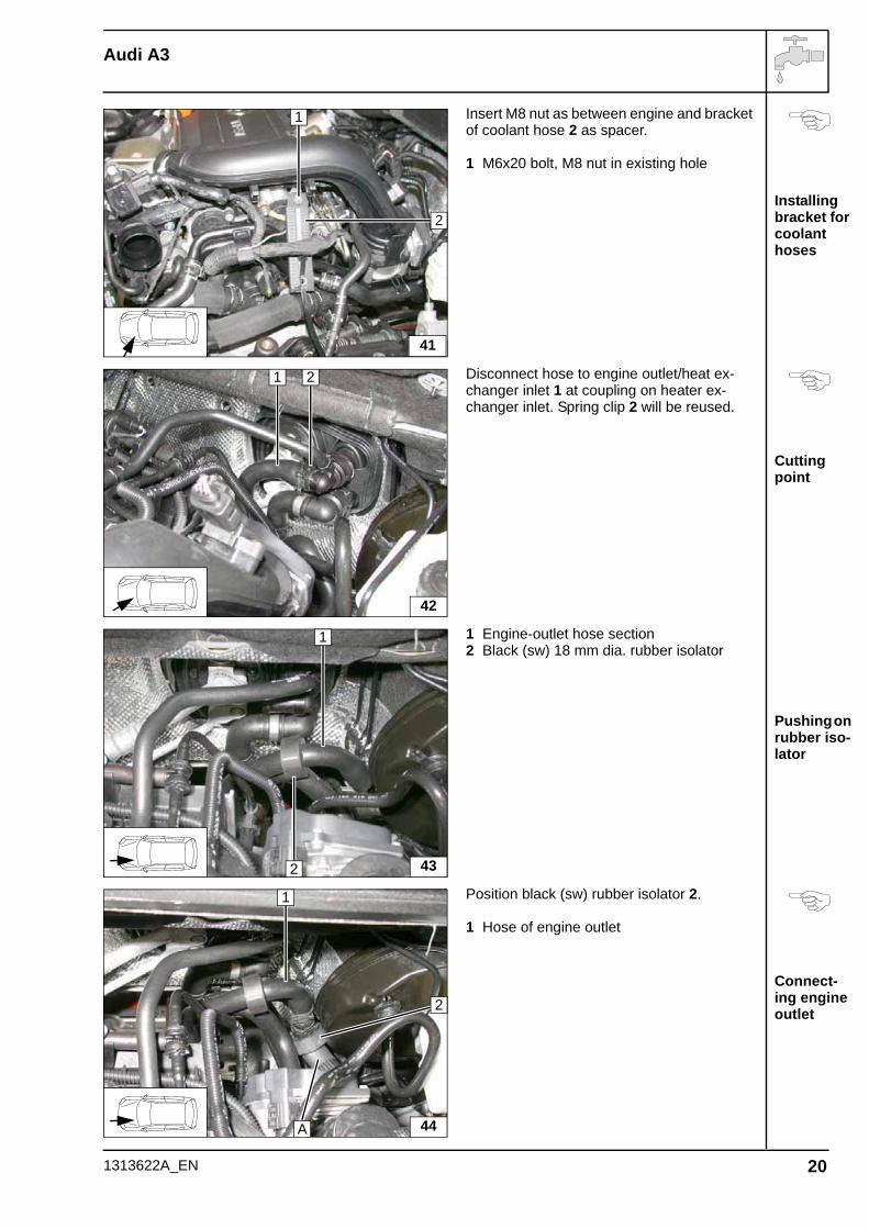
Insert M8 nut as between engine and bracket of coolant hose 2 as spacer.
1 M6x20 bolt, M8 nut in existing hole
Disconnect hose to engine outlet/heat ex-changer inlet 1 at coupling on heater ex-changer inlet. Spring clip 2 will be reused.
1 Engine-outlet hose section2 Black (sw) 18 mm dia. rubber isolator
Position black (sw) rubber isolator 2.
1 Hose of engine outlet
1
41
2
42
1 2
43
1
2
44
1
A
2
1313622A_EN 20
Audi A3
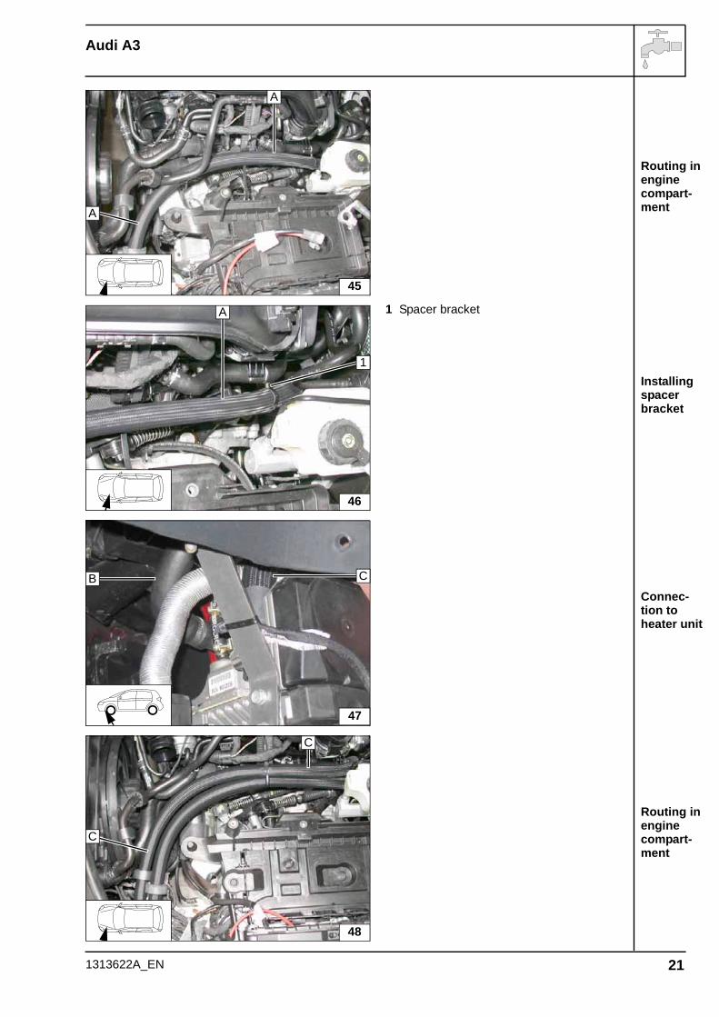
Routing in engine compart-ment
Installing spacer bracket
Connec-tion to heater unit
Routing in engine compart-ment
1 Spacer bracket
45
A
A
46
A
1
47
CB
48
C
C
1313622A_EN 21
Audi A3
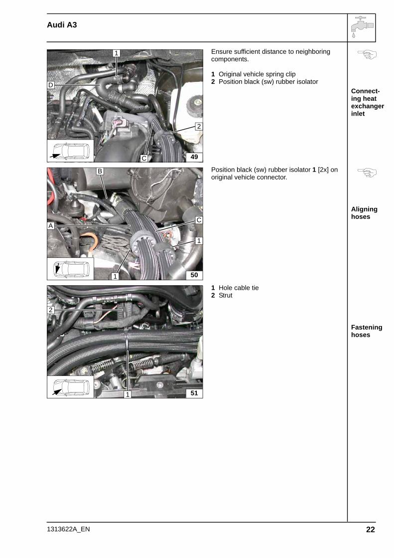
Connect-ing heat exchanger inlet
Aligning hoses
Fastening hoses
Ensure sufficient distance to neighboring components.
1 Original vehicle spring clip2 Position black (sw) rubber isolator
Position black (sw) rubber isolator 1 [2x] on original vehicle connector.
1 Hole cable tie2 Strut
49C
D
1
2
50
CA
B
1
1
51
2
1
1313622A_EN 22
Audi A3
Installing wheel well trim
Hole in un-derride protection
Mounting rubber iso-lator
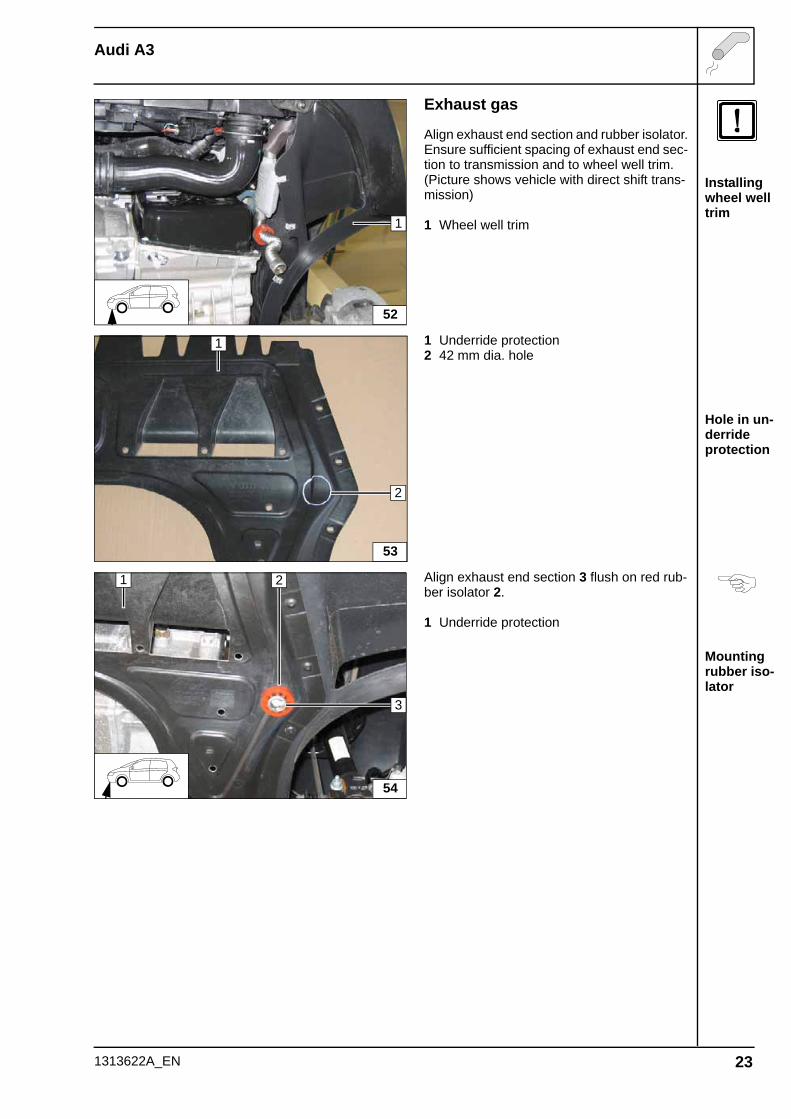
Exhaust gas
Align exhaust end section and rubber isolator.Ensure sufficient spacing of exhaust end sec-tion to transmission and to wheel well trim.(Picture shows vehicle with direct shift trans-mission)
1 Wheel well trim
1 Underride protection2 42 mm dia. hole
Align exhaust end section 3 flush on red rub-ber isolator 2.
1 Underride protection
1
52
53
1
2
2
3
54
1
1313622A_EN 23
Audi A3
Final Work
WARNING!Reassemble the disassembled components in reverse order.
Check all hoses, clamps and all electrical connections for firm seating.
Secure all loose cables using cable ties.
Only use manufacturer-approved coolant.
Spray heater unit components with anti-corrosion wax (Tectyl 100K, Order No. 111 329).
- Connect the battery- Fill and bleed the coolant circuit according to the vehicle manufacturer’s specifications.- Set the digital timer.- Make setting on A/C control panel according to the "Operating Instructions for End Customer".- Check the proper operation of the additional heater, see the operating instructions/installation in-
structions.- Attach the "Switch off additional heater before refueling" sticker to the left-hand B-pillar.
Adjust the sensitivity of the passenger compartment monitoring
WARNING!This can only be carried out at an authorized workshop! Observe the applicable repair manual of the respective vehicle.
- Connect the VAS tester.- Open Item 46 (Central Module of Comfort System)- Go to Item 10 (Adjustment)- Follow the request for the code entry and enter the code 15- Reduce the sensitivity of the passenger compartment monitoring to 50 %- Save this setting- The adjustment of the sensitivity of the passenger compartment monitoring is completed.
Feel the driveWebasto AGPostfach 80 - 82132 StockdorfHotline 01805 / 932278 - Hotfax 0395 / 5592-353http://www.webasto.de
Printed in Germany 11/2008 Printing: Stef-fen
1313622A_EN
Audi A3
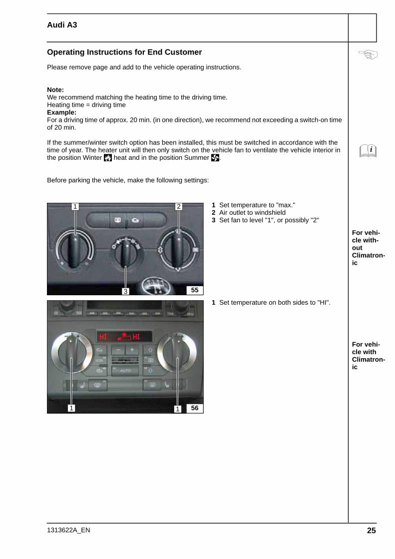
For vehi-cle with-out Climatron-ic
For vehi-cle with Climatron-ic
Operating Instructions for End Customer
Please remove page and add to the vehicle operating instructions.
Note:We recommend matching the heating time to the driving time.Heating time = driving timeExample:For a driving time of approx. 20 min. (in one direction), we recommend not exceeding a switch-on time of 20 min.
If the summer/winter switch option has been installed, this must be switched in accordance with the time of year. The heater unit will then only switch on the vehicle fan to ventilate the vehicle interior in the position Winter heat and in the position Summer .
Before parking the vehicle, make the following settings:
1 Set temperature to "max."2 Air outlet to windshield3 Set fan to level "1", or possibly "2"
1 Set temperature on both sides to "HI".
55
1 2
3
561 1
1313622A_EN 25