Embed Size (px)
Citation preview

Installation Manual
STANDARD CONTROLLER
KS-1012-RS, KS-1024-RS KS-1012-IP, KS-1024-IP
VERSION 2.0

Standard Access Controller – Installation manual
All rights reserved. © AAT HOLDING S.A. 2
1. Introduction ……………………………………………………………………………... 3 2. Controller technical data KS-1024-RS/IP …………………………….…. 5 3. Controller technical data KS-1024-RS/IP ……………………………….. 6 4. System circuit diagram KaDe Premium ………………………………….. 7 5. Controller module KS-1012-RS ………………………………………………. 9
6. Controller module KS-1012-IP ………………………………………………. 11 7. Controller connectors description KS-1012-RS/IP ………………… 12 8. Controller module KS-1024-IP ………………………………………………. 16 9. Controller module KS-1024-RS ……………………………………………… 18 10. Controller connectors description KS-1024-RS/IP ……………… 20 11. Installing the controller in the housing supply ……………………. 22 12. Reader connection ……………………………………………………………….. 25 13. Electric lock connection ………………………………………………………… 26 14. Door contact and exit button connection ……………………………. 27
15. Emergency exit button connection ………………………………………. 27 16. Alarm input / output connection ………………………………….……... 28 17. RS-485 communication connection ……………………………………... 29 18. Change communication mode RS232/485 …………………………… 30 19. Change communication rate ………………………………………………... 30 20. Change controller address ……………………………………………………. 31 21. Convert RS 485 to TCP/IP - KS-1012/24-RS ………………………. 32 22. Connect with router or computer KS-1012/24-IP ………………. 32 23. RS 232 communication connection ……………………………………... 33
24. Clear communication password button ……………………………….. 33 25. Alarm extension board - 4 relay module …………………………….. 34 26. Power supply connection ………………………………………………………. 35 27. Notes for installation …………………………………………………………….. 36 28. Wire Requirement …………………………………………………………………. 37 29. Trouble-Shooting ………………………………………………………………….. 38
CONTENTS

Standard Access Controller – Installation manual
All rights reserved. © AAT HOLDING S.A. 3
Summary Introduction
KS-1012/24-RS/IP series controllers were designed and developed for use
in access control system. It is a high-tech product series which integrate infor-mation management, computer control and smart card technology. With indus-
trialized design, the controller adopts dedicated four-layer and high-end CPU, and all components adopt original binding chip. All these characteristics contrib-
ute to the high-performance and reliability of the product.
KaDe Premium, the software for KS-1012/24-RS/IP controller series, is a power-ful control and attendance management system. KaDe Premium is a self-owned
technology and new generation one-card-solution smart management system. Based on one-card-solution structure, more functions are added on
current access control system. The system supports Batch Operation, Self-
defined Extension Output, Automatic Download during Different Times, Various Door-open Modes in Various Time Sections and Dismiss/Activate Security Func-
tion etc.
KaDe Premium can manage access group setup, display and record all real time event data. It can display the following information: card holder (name,
photo), event time, door address and event type (working hours, work over-time, read card during non-working hours, invalid card and so on).
Moreover, in case of unexpected event, KaDe Premium can trigger alarm and snapshot. KaDe Premium can also work with building automation, CCTV
monitoring, guard against theft, fire-control and alarm and so on.
KS series controller: KS-1012-RS, KS-1024-RS, KS-1012-IP , KS-1024-IP .
Notice: KS-1012/24-RS/IP controller series only work with
KaDe Premium software.
Symbol Controller description
KS-1012-RS Standard controller, one door-two way, two doors-one way, 2 readers ports, RS232 and
RS485 port, 20 000 cards, 50 000 events, 20 000 alarms
KS-1024-RS Standard controller, two doors-two way, four doors-one way, 4 readers ports, RS232
and RS485 port, 20 000 cards, 50 000 events, 20 000 alarms
KS-1012-IP Standard controller, one door-two way, two doors-one way, 2 readers ports, TCP port,
20 000 cards, 50 000 events, 20 000 alarms
KS-1024-IP Standard controller, two doors-two way, four doors-one way, 4 readers ports, TCP port,
20 000 cards, 50 000 events, 20 000 alarms

Standard Access Controller – Installation manual
All rights reserved. © AAT HOLDING S.A. 4
Installation Steps
1.1 Switch off all system power supplies. 1.2 Ensure correct components connection.
1.3 Connect the system in accordance with the wiring diagram. Please turn off computer and power off before connecting controller with computer.
1.4 Change controller communication mode (232 / 485 mode), communication rate, and communication address.
1.5 Check the connection again.
1.6 Switch on the power supply and start computer.
Definitions and Terminologies
Wiegand protocol:
Wiegand protocol is an interface protocol by which the ID identifying device sends data to access controller. Wiegand protocol is an uni-directional protocol
and is downward only. It is composed of two data channels. Normal Open:
Under normal situation, the common end (C) and Normal open end (NO) of out-put or input interfaces are not connected.
Normal Close: Under normal situation, the common end (C) and Normal open end (NO) of out-
put or input interface are short-circuited. Fail-safe/ Fail-secure:
In Fail-safe mode, the lock keeps locked when power off. In Fail-secure mode, the lock keeps locked until power on.
Baud Rate: A kind of communication rate (unit is bit/s (bps)). Two devices can communicate
only when they have the same baud rate.
Dry Contact: A type of switch input mode without any voltage or current.
Controller Address On the same bus, each device must have an unique identification code. KS
controllers adopts address code as identification code. Reset Switch:
The reset switch is used to hot-recover the controller during debugging or in case of special situations. The hot-recovery will neither affects the storage of
controller, nor user setups. Alarm Interworking:
Different inputs can control different exterior devices by connecting to different outputs. Here is one example: reader triggers DVR to snapshot or video record-
ing. Controller Failure:
Controller does not respond to any input and output, or only responds to part of
input/output.

Standard Access Controller – Installation manual
All rights reserved. © AAT HOLDING S.A. 5
Parameter
or function name
Parameter value
or function description
Buffer capacity
- Card buffer 20 000
- Event buffer
- Alarm buffer
50 000
20 000
Electrical parameter
- Supply power / Current load 9 - 15 VDC / <110 mA
Environment parameter
- Environment For indoor installation only
- Working Temperature From -10°C to +55°C
- Relative Humidity 10% - 90%
- Size (L x W X H) 160 x 110 mm
- Cabinet size (L x W X H) 350 x 300 x 100 mm
Communication ports
Direct PC connection - RS232 | - TCP
Network connection (bus) - RS485 |
Readers & cards
- readers ports 2 ports - Wiegand interface
- card formats 26 /34 bit Wiegand, self-defined (26 - 40 bit)
- keypads format 4-bits, without buffering
Inputs
- door contact input NO / NC - 2 inputs
- exit button input NO / NC - 2 inputs
- general inputs NO / NC - 4 inputs
Outputs
- lock control Relays type DC 12V 3A - 1-2 outputs
- door alarm control Relays type DC 12V 3A - 1-2 outputs
- general alarm (controller board) Relays type DC 12V 3A - 4-2 outputs
- general alarm (module board - option) Relays type DC 12V 3A - 4 outputs
Access level
- access levels 200 in system / 42 in controller
- schedules 184 in system / 16 in controller
- holidays 64 x 32 days in system / 16 in controller
Identification mode Card, PIN, Card or PIN, Card + PIN
Alarm relive Synchronize with input state or delay
KS-1012-RS/IP Controller Technical Data

Standard Access Controller – Installation manual
All rights reserved. © AAT HOLDING S.A. 6
Parameter
or function name
Parameter value
or function description
Buffer capacity
- Card buffer 20 000
- Event buffer
- Alarm buffer
50 000
20 000
Electrical parameter
- Supply power / Current load 9 - 15 VDC / <110 mA
Environment parameter
- Environment For indoor installation only
- Working Temperature From -10°C to +55°C
- Relative Humidity 10% - 90%
- Size (L x W X H) 119 x 187 mm
- Cabinet size (L x W X H) 350 x 300 x 100 mm
Communication ports
Direct PC connection - RS232 | - TCP
Network connection (bus) - RS485 |
Readers & cards
- readers ports 4 ports - Wiegand interface
- card formats 26 /34 bit Wiegand, self-defined (26 - 40 bit)
- keypads format 4-bits, without buffering
Inputs
- door contact input NO / NC - 4 inputs
- exit button input NO / NC - 4 inputs
- general inputs NO / NC - 4 inputs
Outputs
- lock control Relays type DC 12V 3A - 2-4 outputs
- door alarm control Relays type DC 12V 3A - 2-4 outputs
- general alarm (controller board) Relays type DC 12V 3A - 4-0 outputs
- general alarm (module board - option) Relays type DC 12V 3A - 4 outputs
Access level
- access levels 200 in system / 42 in controller
- schedules 184 in system / 16 in controller
- holidays 64 x 32 days in system / 16 in controller
Identification mode Card, PIN, Card or PIN, Card + PIN
Alarm relive Synchronize with input state or delay
KS-1024-RS/IP Controller Technical Data

Standard Access Controller – Installation manual
All rights reserved. © AAT HOLDING S.A. 7
- u
p t
o 4
096
reade
rs- u
p t
o 1
024
co
ntr
oll
ers
- u
p t
o 2
0 N
etw
ork
s R
S4
85
- u
p t
o 3
2 c
on
troll
ers
in
one
Netw
ork
- 1
Work
sta
tio
n
Sys
tem
capa
cit
yL
AN
/ W
AN
LA
N /
WA
N
Co
nve
rte
rR
S2
32
/48
5
Adm
inC
ard
Read
er
Re
ade
r
C-1
0
Read
er
C-2
0R
eader
C-7
0C
on
trolle
r (1
)K
S-1
012-R
S
Con
trolle
r (3
2)
KS
-1024-R
S
Serv
er
Ka
De
Re
ad
er
C-6
0
Co
nve
rter
TC
P/4
85
Contr
oller
KS
-101
2-I
PC
ontr
olle
rK
S-1
02
4-I
P
Sy
stem
cir
cu
it d
iag
ram
KaD
e P
rem
ium

Standard Access Controller – Installation manual
All rights reserved. © AAT HOLDING S.A. 8
KS-1012-RS controller module

Standard Access Controller – Installation manual
All rights reserved. © AAT HOLDING S.A. 9
KS-1012-RS controller module
Description of connections - two doors, one-way control
Alarm input. 4 Alarm input. 3
Alarm input. 2 Alarm input. 1
Door 2 contact Door 2 exit button
Door 1 contact Door 1 exit button
Door 2 - entry Reader port 2
Door 1 - entry Reader port 1
TX RX
RS-485 port
Door 1 - lock
Door 1 - alarm
Door 2 - lock
Door 2 - alarm
Alarm output 1
Alarm output 2
Power supply +12VDC
ALR4
GND
ALR3
ALR2
GND
ALR1
D_S2
GND
AN2
D_S1
GND
AN1
NULL
2BUZ
2D1
2D0
2RD+
2RD-
NULL
1BUZ
1D1
1D0
1RD+
1RD-
+ 485
- 485
GND
1C
1NC
1NO
2C
2NC
2NO
3C
3NC
3NO
4C
4NC
4NO
5C
5NC
5NO
6C
6NC
6NO
12V
12V
GND
GND
Address Baud
rate
RS232
Communication
port Port selection RS232/485
LEDs TX RX
Reset button Clear communication password
button
Read card OK LED
Alarm Extension Board Interface
R 1
R 2
R 3
R 4
R 5
R 6

Standard Access Controller – Installation manual
All rights reserved. © AAT HOLDING S.A. 10
KS-1012-RS controller module
Description of connections - one door, two-way control
Alarm input. 4 Alarm input. 3
Alarm input. 2 Alarm input. 1
Not used
Door 1 contact Door 1 exit button
Door 1 - exit Reader port 2
Door 1 - entry Reader port 1
TX RX
RS-485 port
Door 1 - lock
Door 1 - alarm
Alarm output 1
Alarm output 2
Alarm output 3
Alarm output 4
Power supply +12VDC
ALR4
GND
ALR3
ALR2
GND
ALR1
D_S2
GND
AN2
D_S1
GND
AN1
NULL
2BUZ
2D1
2D0
2RD+
2RD-
NULL
1BUZ
1D1
1D0
1RD+
1RD-
+ 485
- 485
GND
1C
1NC
1NO
2C
2NC
2NO
3C
3NC
3NO
4C
4NC
4NO
5C
5NC
5NO
6C
6NC
6NO
12V
12V
GND
GND
Address Baud
rate
RS232
Communication
port Port selection RS232/485
LEDs TX RX
Reset button Clear communication password
button
Read card OK LED
Alarm Extension Board Interface
R 1
R 2
R 3
R 4
R 5
R 6

Standard Access Controller – Installation manual
All rights reserved. © AAT HOLDING S.A. 11
KS-1012-IP controller module
Description of connections - two doors, one-way control
Alarm input. 4 Alarm input. 3
Alarm input. 2 Alarm input. 1
Door 2 contact Door 2 exit button
Door 1 contact Door 1 exit button
Door 2 - entry Reader port 2
Door 1 - entry Reader port 1
Door 1 - lock
Door 1 - alarm
Door 2 - lock
Door 2 - alarm
Alarm output 1
Alarm output 2
Power supply +12VDC
Reset button Clear communication password
button
Read card OK LED
Alarm Extension Board Interface
R 1
R 2
R 3
R 4
R 5
R 6
ALR4
GND
ALR3
ALR2
GND
ALR1
D_S2
GND
AN2
D_S1
GND
AN1
NULL
2BUZ
2D1
2D0
2RD+
2RD-
NULL
1BUZ
1D1
1D0
1RD+
1RD-
1C
1NC
1NO
2C
2NC
2NO
3C
3NC
3NO
4C
4NC
4NO
5C
5NC
5NO
6C
6NC
6NO
12V
12V
GND
GND
TCP Communication port
Standard Access Controller – Installation manual
All rights reserved. © AAT HOLDING S.A. 12
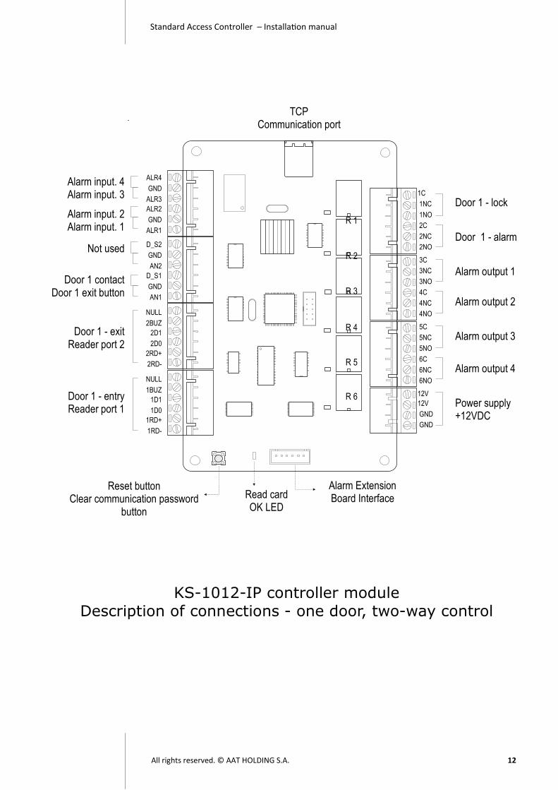
KS-1012-IP controller module
Description of connections - one door, two-way control
Alarm input. 4 Alarm input. 3
Alarm input. 2 Alarm input. 1
Not used
Door 1 contact Door 1 exit button
Door 1 - exit Reader port 2
Door 1 - entry Reader port 1
Door 1 - lock
Door 1 - alarm
Alarm output 1
Alarm output 2
Alarm output 3
Alarm output 4
Power supply +12VDC
Reset button Clear communication password
button
Read card OK LED
Alarm Extension Board Interface
R 1
R 2
R 3
R 4
R 5
R 6
ALR4
GND
ALR3
ALR2
GND
ALR1
D_S2
GND
AN2
D_S1
GND
AN1
NULL
2BUZ
2D1
2D0
2RD+
2RD-
NULL
1BUZ
1D1
1D0
1RD+
1RD-
1C
1NC
1NO
2C
2NC
2NO
3C
3NC
3NO
4C
4NC
4NO
5C
5NC
5NO
6C
6NC
6NO
12V
12V
GND
GND
TCP Communication port

Standard Access Controller – Installation manual
All rights reserved. © AAT HOLDING S.A. 13
FUNCTION Symbol Section name Section name Symbol FUNCTION
Input 4 ALR4
Alarm inputs
Communication
port
Alarm relays
-
Outputs con-
trol
485+
Communication
port RS-485 GND GND 485-
Input 3 ALR3 GND
Input 2 ALR2 1C
Lock relay
Door #1 GND GND 1NC
Input 1 ALR1 1NO
2C
Alarm relay
Door #1 Null D_S2 2NC
Null GND 2NO
Null AN2
Door magnet input D_S1 Door #1
Door contact
Exit button
3C
Alarm relay
Output #1 GND GND 3NC
Exit button input AN1 3NO
4C
Alarm relay
Output #2 Null NULL
Door #1
Exit reader port
4NC
LED or buzzer 2BUZ 4NO
Wiegand 1 2D1 5C
Alarm relay
Output #3 Wiegand 0 2D0 5NC
Reader power +12V 2RD+ 5NO
Reader power -12V 2RD- 6C
Alarm relay
Output #4 6NC
Null NULL
Door #1
Entry reader
port
6NO
LED or buzzer 1BUZ
Wiegand 1 1D1 +12V
Controller power
+12V
Wiegand 0 1D0 +12V
Reader power +12V 1RD+ GND
Reader power -12V 1RD- GND
Controller connectors description - KS-1012-RS /IP - one-door two-way
Relays
Door #1
Controller
power

Standard Access Controller – Installation manual
All rights reserved. © AAT HOLDING S.A. 14
FUNCTION Symbol Section name Section name Symbol FUNCTION
Input 4 ALR4
Alarm inputs
Communication
port
Alarm relays
-
Outputs con-
trol
485+
Communication
port RS-485 GND GND 485-
Input 3 ALR3 GND
Input 2 ALR2 1C
Lock relay
Door #1 GND GND 1NC
Input 1 ALR1 1NO
2C
Alarm relay
Door #1 Door magnet input D_S1 2NC Door #2
Door contact
Exit button
GND GND 2NO
Exit button input AN1
Door magnet input D_S1 Door #1
Door contact
Exit button
3C
Lock relay
Door #2 GND GND 3NC
Exit button input AN1 3NO
4C
Alarm relay
Door #2 Null NULL
Door #2
Entry reader
port
4NC
LED or buzzer 2BUZ 4NO
Wiegand 1 2D1 5C
Alarm relay
Output #1 Wiegand 0 2D0 5NC
Reader power +12V 2RD+ 5NO
Reader power -12V 2RD- 6C
Alarm relay
Output #2 6NC
Null NULL
Door #1
Entry reader
port
6NO
LED or buzzer 1BUZ
Wiegand 1 1D1 +12V
Controller power
+12V
Wiegand 0 1D0 +12V
Reader power +12V 1RD+ GND
Reader power -12V 1RD- GND
Controller connectors description - KS-1012-RS /IP - two-door one-way
Relays
Door #1
Controller
power
Relays
Door #12

Standard Access Controller – Installation manual
All rights reserved. © AAT HOLDING S.A. 15
KS-1024-IP controller module

Standard Access Controller – Installation manual
All rights reserved. © AAT HOLDING S.A. 16
KS-1024-RS controller module
Description of connections - four doors, one-way control
TX RX
Alarm input 4 Alarm input 3
Alarm input 2 Alarm input 1
Door 4 contact Door 4 exit button
Door 3 contact Door 3 exit button
Door 2 contact Door 2 exit button
Door 1 contact Door 1 exit button
Door 4 - entry Reader port 4
Door 3 - entry Reader port 3
Door 2 - entry Reader port 2
Door 1 - entry Reader port 1
RS-485 port
Door 1 - lock
Door 1 - alarm
Door 2 - lock
Door2 - alarm
Door 3 - lock
Door 3 - alarm
Door 4 - lock
Door4 - alarm
Supply power +12VDC
ALR4
GND
ALR3
ALR2
GND
ALR1
D_S4
GND
AN4
D_S3
GND
AN3
D_S2
GND
AN2
D_S1
GND
AN1
4BUZ
4RD1
4RD0
RD+
RD-
3BUZ
3RD1
3RD0
2BUZ
2RD1
2RD0
RD+
RD-
1BUZ
1RD1
1RD0
+ 485
- 485
GND
1C
1NC
1NO
2C
2NC
2NO
3C
3NC
3NO
4C
4NC
4NO
5C
5NC
5NO
6C
6NC
6NO
7C
7NC
7NO
8C
8NC
8NO
12V
12V
GND
GND
PK 1
PK 2
PK 3
PK 4
PK 5
PK 6
PK 7
PK 8
Address Baud
rate
RS232
Communication
port Port selection RS232/485
LEDs TX RX
Reset button Clear communication
password button
Read card OK LED
Alarm Extension Board Interface
Standard Access Controller – Installation manual
All rights reserved. © AAT HOLDING S.A. 17
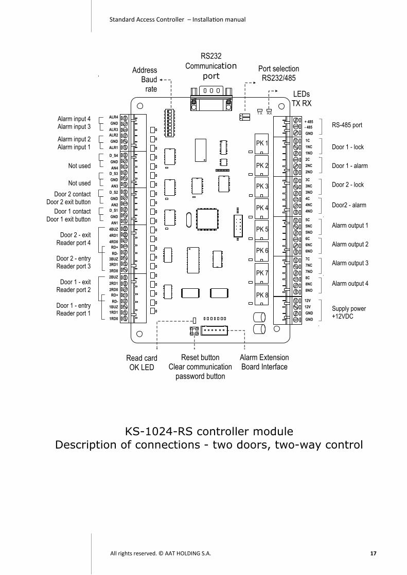
KS-1024-RS controller module
Description of connections - two doors, two-way control
TX RX
Alarm input 4 Alarm input 3
Alarm input 2 Alarm input 1
Not used
Not used
Door 2 contact Door 2 exit button
Door 1 contact Door 1 exit button
Door 2 - exit
Reader port 4
Door 2 - entry Reader port 3
Door 1 - exit
Reader port 2
Door 1 - entry Reader port 1
RS-485 port
Door 1 - lock
Door 1 - alarm
Door 2 - lock
Door2 - alarm
Alarm output 1
Alarm output 2
Alarm output 3
Alarm output 4
Supply power +12VDC
ALR4
GND
ALR3
ALR2
GND
ALR1
D_S4
GND
AN4
D_S3
GND
AN3
D_S2
GND
AN2
D_S1
GND
AN1
4BUZ
4RD1
4RD0
RD+
RD-
3BUZ
3RD1
3RD0
2BUZ
2RD1
2RD0
RD+
RD-
1BUZ
1RD1
1RD0
+ 485
- 485
GND
1C
1NC
1NO
2C
2NC
2NO
3C
3NC
3NO
4C
4NC
4NO
5C
5NC
5NO
6C
6NC
6NO
7C
7NC
7NO
8C
8NC
8NO
12V
12V
GND
GND
PK 1
PK 2
PK 3
PK 4
PK 5
PK 6
PK 7
PK 8
Address Baud
rate
RS232
Communication
port Port selection RS232/485
LEDs TX RX
Reset button Clear communication
password button
Read card OK LED
Alarm Extension Board Interface

Standard Access Controller – Installation manual
All rights reserved. © AAT HOLDING S.A. 18
KS-1024-IP controller module
Description of connections - four doors, one-way control
Alarm input 4 Alarm input 3
Alarm input 2 Alarm input 1
Door 4 contact Door 4 exit button
Door 3 contact Door 3 exit button
Door 2 contact Door 2 exit button
Door 1 contact Door 1 exit button
Door 4 - entry Reader port 4
Door 3 - entry Reader port 3
Door 2 - entry Reader port 2
Door 1 - entry Reader port 1
Door 1 - lock
Door 1 - alarm
Door 2 - lock
Door2 - alarm
Door 3 - lock
Door 3 - alarm
Door 4 - lock
Door4 - alarm
Supply power +12VDC
ALR4
GND
ALR3
ALR2
GND
ALR1
D_S4
GND
AN4
D_S3
GND
AN3
D_S2
GND
AN2
D_S1
GND
AN1
4BUZ
4RD1
4RD0
RD+
RD-
3BUZ
3RD1
3RD0
2BUZ
2RD1
2RD0
RD+
RD-
1BUZ
1RD1
1RD0
1C
1NC
1NO
2C
2NC
2NO
3C
3NC
3NO
4C
4NC
4NO
5C
5NC
5NO
6C
6NC
6NO
7C
7NC
7NO
8C
8NC
8NO
12V
12V
GND
GND
PK 1
PK 2
PK 3
PK 4
PK 5
PK 6
PK 7
PK 8
Reset button Clear communication
password button
Read card OK LED
Alarm Extension Board Interface
TCP Communication port

Standard Access Controller – Installation manual
All rights reserved. © AAT HOLDING S.A. 19
KS-1024-IP controller module
Description of connections - two doors, two-way control
Door 1 - lock
Door 1 - alarm
Door 2 - lock
Door2 - alarm
Alarm output 1
Alarm output 2
Alarm output 3
Alarm output 4 Supply power +12VDC
ALR4
GND
ALR3
ALR2
GND
ALR1
D_S4
GND
AN4
D_S3
GND
AN3
D_S2
GND
AN2
D_S1
GND
AN1
4BUZ
4RD1
4RD0
RD+
RD-
3BUZ
3RD1
3RD0
2BUZ
2RD1
2RD0
RD+
RD-
1BUZ
1RD1
1RD0
1C
1NC
1NO
2C
2NC
2NO
3C
3NC
3NO
4C
4NC
4NO
5C
5NC
5NO
6C
6NC
6NO
7C
7NC
7NO
8C
8NC
8NO
12V
12V
GND
GND
PK 1
PK 2
PK 3
PK 4
PK 5
PK 6
PK 7
PK 8
Reset button Clear communication
password button
Read card OK LED
Alarm Extension Board Interface
TCP Communication port
Alarm input 4 Alarm input 3
Alarm input 2 Alarm input 1
Not used
Not used
Door 2 contact Door 2 exit button
Door 1 contact Door 1 exit button
Door 2 - exit
Reader port 4
Door 2 - entry Reader port 3
Door 1 - exit
Reader port 2
Door 1 - entry Reader port 1

Standard Access Controller – Installation manual
All rights reserved. © AAT HOLDING S.A. 20
Controller connectors description - KS-1024-RS /IP - two-door two-way
FUNCTION Symbol Section name Section name Symbol FUNCTION
Input 4 ALR4
Alarm inputs
Communication
port
485+
Communication
port RS-485 GND GND 485-
Input 3 ALR3 GND
Input 2 ALR2
Relays
Door #1
1C
Lock relay
Door #1 GND GND 1NC
Input 1 ALR1 1NO
Null D_S4 2C
Alarm relay
Door #1 Null GND 2NC
Null AN4 2NO
Null D_S3
Relays
Door #2
1C
Lock relay
Door #2 Null GND 1NC
Null AN3 1NO
Door magnet input D_S2 Door #2
Door contact
Exit button
2C
Alarm relay
Door #2 GND GND 2NC
Exit button input AN2 2NO
Door magnet input D_S1 Door #1
Door contact
Exit button
1C
Alarm relay
Output #1
Alarm relays
-
Outputs control
GND GND 1NC
Exit button input AN1 1NO
LED or buzzer 4BUZ Door #2
Exit reader port
2C
Alarm relay
Output #2 Wiegand 1 4D1 2NC
Wiegand 0 4D0 2NO
Reader power +12V RD+
Reader power
1C
Alarm relay
Output #3 Reader power -12V RD- 1NC
LED or buzzer 3BUZ Door #2
Entry reader
port
1NO
Wiegand 1 3D1 2C
Alarm relay
Output #4 Wiegand 0 3D0 2NC
LED or buzzer 2BUZ Door #1
Exit reader port
2NO
Wiegand 1 2D1
Wiegand 0 2D0
Reader power +12V RD+
Reader power Reader power -12V RD-
Controller
power
+12V
Controller power
+12V
LED or buzzer 1BUZ Door #1
Entry reader
port
+12V
Wiegand 1 1D1 GND
Wiegand 0 1D0 GND

Standard Access Controller – Installation manual
All rights reserved. © AAT HOLDING S.A. 21
Controller connectors description - KS-1024-RS /IP - four-door one-way
FUNCTION Symbol Section name Section name Symbol FUNCTION
Input 4 ALR4
Alarm inputs
Communication
port
485+
Communication
port RS-485 GND GND 485-
Input 3 ALR3 GND
Input 2 ALR2
Relays
Door #1
1C
Lock relay
Door #1 GND GND 1NC
Input 1 ALR1 1NO
Door magnet input D_S4 Door #4
Door contact
Exit button
2C
Alarm relay
Door #1 GND GND 2NC
Exit button input AN4 2NO
Door magnet input D_S3 Door #3
Door contact
Exit button
Relays
Door #2
1C
Lock relay
Door #2 GND GND 1NC
Exit button input AN3 1NO
Door magnet input D_S2 Door #2
Door contact
Exit button
2C
Alarm relay
Door #2 GND GND 2NC
Exit button input AN2 2NO
Door magnet input D_S1 Door #1
Door contact
Exit button
1C
Lock relay
Door #3
Relays
Door #3
Relays
Door #4
GND GND 1NC
Exit button input AN1 1NO
LED or buzzer 4BUZ Door #4
Entry reader
port
2C
Alarm relay
Door #3 Wiegand 1 4D1 2NC
Wiegand 0 4D0 2NO
Reader power +12V RD+
Reader power
1C
Lock relay
Door #4 Reader power -12V RD- 1NC
LED or buzzer 3BUZ Door #3
Entry reader
port
1NO
Wiegand 1 3D1 2C
Alarm relay
Door #4 Wiegand 0 3D0 2NC
LED or buzzer 2BUZ Door #2
Entry reader
port
2NO
Wiegand 1 2D1
Wiegand 0 2D0
Reader power +12V RD+
Reader power Reader power -12V RD-
Controller
power
+12V
Controller power
+12V
LED or buzzer 1BUZ Door #1
Entry reader
port
+12V
Wiegand 1 1D1 GND
Wiegand 0 1D0 GND

Standard Access Controller – Installation manual
All rights reserved. © AAT HOLDING S.A. 22
Installing the controller in the housing
Controller module must be installed in a dedicated buffer power supply housing proper for the controller model.
There are two dedicated housing: APS-AAT-2A - designed for controllers KS-1012-RS/IP (2 readers)
APS-AAT-3A - designed for controllers KS-1024-RS/IP (4 readers)
Power supplies installed in these enclosures are performance as a symbol in the
name of 2A and 3.5 A. This performance allows the power supply controller mod-ule, 2 or 4 readers and 2 or 4 electric locks (even electromagnetics lock for cur-
rent consumption 500mA). The housings are designed to be installed inside the battery with a capacity 7Ah (in vertical position, in a special holder - as pictured
on the next page.
Connections inside the case: - output voltage (12V), connect the terminal controller
- terminals "TAMPER" power connector into an available detector line input controller
- to the terminals at the edges of the controller attach cables from readers, locks, keys and door status sensor (door magnet)
- red (+) and black (-) cable from the power supply connected to the battery
terminals - 230 VAC mains plug to power cubes on top of the housing (through the exist-
ing fuse)
After completing all connections enable the supply voltage 230 V and validate the operation of the controller.
Housing has a removable door, which can be removed after unscrewing the cable
mass. Housing is closed on the two bolts screwed on the right edge.
Opening of the sensor housing is monitored sabotage. Connect it to the free in-
put detector line in controller and activate the program so that the alarm was generated.
Look at diagram on next pages for details.

Standard Access Controller – Installation manual
All rights reserved. © AAT HOLDING S.A. 23
APS-AAT-2A - Supply power and metal cabinet for KS-1012-RS/IP
APS-AAT-3A - Supply power and metal cabinet for KS-1024-RS/IP

Standard Access Controller – Installation manual
All rights reserved. © AAT HOLDING S.A. 24
Contr
olle
rm
od
ule
KS
-10
12
/24
Wir
ing
dia
gra
m in
sid
e
po
we
r su
pp
ly
to t
he
sta
nd
ard
co
ntr
olle
rs K
ad
e
Sup
ply
po
we
r12
V 2
/ 3
,5 A
Radiator
Ba
ttery
12V
7A
h
AC
tra
nsfo
rme
r2
30V
AC
/ 1
7VA
C10
0 V
A
Fuse1A /250V
4 Relay module17
VA
C
Tam
per
po
kryw
y
Ta
mp
er
+
-
-
+
230V
AC
GN
D
Do
ors
LN
GN
D

Standard Access Controller – Installation manual
All rights reserved. © AAT HOLDING S.A. 25
Reader connection
Function Reader 1 Reader 2 Color
Supply power - 1RD- 2RD- Black
Supply power + 1RD+ 2RD+ Red
Wiegand D0 1D0 2D0 Green
Wiegand D1 1D1 2D1 White
BUZ / LED 1BUZ 2BUZ Grey/Blue
Remark
Wire: 6-core screen wire or FTP-5 8-core screen twisted-pair
Distance: Distance between controller and reader ≤ 60m
Note: Reader should be of the same format as in the software.
Reader Connection Indicator: When user presents card to the reader,
RD_ OK light will flash one time only when the connection between reader and controller is correct and controller interface works properly, otherwise, RD_ OK
light will not respond (Hardware V1.2 or above is supported only).
BUZ/ LED - lock state control wire can be connected with LED or BUZ. When lock relay is activated, BUZ will beep or LED will be light until the lock re-
lay is deactivated again ( Hardware V1.2 or above is supported only).
Reader interface indicator OK LED Reader
Outputs for connection reader
LED or Buzzer
Controller module RD_OK
Inputs Door contact/Exit Reader 2 Reader 1
NU
LL
1BU
Z
1D1
1D0
1RD
+ 1R
D-
NU
LL
1BU
Z
1D1
1D0
1RD
+ 1R
D-
Colours of wires in the table below

Standard Access Controller – Installation manual
All rights reserved. © AAT HOLDING S.A. 26
Electric strike NC type connection
Electromagnetic lock NO type connection
Remark
Wire: 2-core power supply wire. Power Supply:DC12V. Distance: Within 150 m
Suggestion: electric lock and controller power supply should be separated, and
Remark
Wire: 2-core power supply wire. Power Supply:DC12V. Distance: Within 150 m
Connector Door1 Door 2
C 1C 2C
NO 1NO 2NO
Controller module
RS-485 Output Supply pow. Lock/Alarm D1 Lock/Alarm D2
1C
1NC
1N
O
2C
2NC
2N
O
Supply power
Electromagnetic lock - NC type
Connector Door 1 Door 2
C 1C 2C
NC 1NC 2NC
Controller module
Supply power
1C
1NC
1N
O
2C
2NC
2N
O
Electromagnetic lock - NO type
RS-485 Output Supply pow. Lock/Alarm D1 Lock/Alarm D2

Standard Access Controller – Installation manual
All rights reserved. © AAT HOLDING S.A. 27
Electromagnetic lock NO type
Supply power
Emergency exit button
Alarm siren or
controller inputs
Lock relay
NC C NO
Remark Wire: 4-core wire
Note: C is public terminal Normal situation: C-NC is pass, C– NO is open
When glass is broken: C– NC is open, C-NO is pass
Controller module
Door contact and exit button connection
Emergency exit button connection
Connector Door 1 Door 2
Ground GND GND
Contact D_S1 D_S2
Button AN1 AN2
Remark
Wire: 2-core screen wire. Distance: Within 150m Note: Input type of exit button and door-magnet should be the same as in the
software.
Controller module
D_S
2 G
ND
AN
2 D
_S1
GN
D
AN
1
Door contact Exit button
Inputs Door contact/Exit Reader 2 Reader 1

Standard Access Controller – Installation manual
All rights reserved. © AAT HOLDING S.A. 28
Alarm input / output connection
The connection cable between the controller and devices - installation cable (multi-wires) The siren alarm and detector - any model.
NOTES
Sensor
Alarm siren
The figure shows an sample connection
GN
D
ALR
1
5C
5NC
5NO
Supply power
Electric lock and alarm outputs working principle
NO (Normal Open) - open contact (open to COM) in the normal state (relay energized) NC (Normal Close) - contact closed (shorted to COM) in the normal state (relay energized)
COM (Common) - a common contact relay circuit NOTES
Contacts NC i COM close Contacts NO i COM open
Contacts NC i COM open Contacts NO i COM close
COM
NO
NC
COM
NO
NC
Relay on controller board in normal state (without supply)
Relay on controller board in active state (supply from controller circuit)
Relay Relay
+12 V supply power of lock GND
Lock NC type or alarm siren
+12 V supply power of lock GND
Lock NC type or alarm siren

Standard Access Controller – Installation manual
All rights reserved. © AAT HOLDING S.A. 29
RS-485 communication connection
Remark
Wire: UTP-5 - 8-core screen twisted-pair (use two pair)
Distance: 800m (Theoretical distance is 1200m. In practical application, distance is around 800m. To prolong the distance, repeater should be added).
Converter: Active converter ( Passive converter should be avoided since it may cause communication problem)
Jumper: Jump to 485 position Suggestion: USB converter and passive converter are not recommended in big-
ger installation. 485 communication light: RX and TX will flash only when controller is in
communication state. When RX and TX connection is reversed, RX light will be Light all the
time (Yellow light), (Hardware V1.2 or above is supported only) .
TXRX
RS485 Transmission LED RX TX
Controller module KS-1012/24-RS
RS485 port
Jumper’s
GND - 485
+ 485
Communication converter RS485
KaDe Premium workstation
RS232 port
Controller connection to RS485 network Recommended connection structure, hand-in-hand connection. Star–type
connection is not recommended. The system may have up to 20 bus.
KS-1012/24-RS KS-1012/24-RS KS-1012/24-RS KS-1012/24-RS KS-1012/24-RS KS-1012/24-RS KS-1012/24-RS
NOTES

Standard Access Controller – Installation manual
All rights reserved. © AAT HOLDING S.A. 30
Change Communication Rate
Remark KS-1012/24-RS controller series can connect with computer by 9600bps (ON pos.) and 19200bps(OFF pos.) communication rate (default setting is 19200bps). Controller baud
rate must be the same as the baud rate of the serial port on software.
Change communication mode
Remark
Controller can connect with PC via RS 232 or RS485 (trough converter). Make sure JP1 is on the right position. Do not change communication mode by hori-
zontal jump. RS 485 communication mode can connect max. 32 controllers.
RS232 RS485 RS232 RS485
JP1 JP1 RS232 RS485
RS
232
RS
485
RS
232
RS
485
Baud rate dipswitch no.8
19200 bps 9600 bps
Microswitch slider

Standard Access Controller – Installation manual
All rights reserved. © AAT HOLDING S.A. 31
Change controller address
Remark Change the identification address of DIP switch SW1. This setup is to KS-1012/24-RS. The controller address can be set as the following: Note: Default address is 0 - all DIP switches in the ON position - on the right. Every bus can connect 32 controllers. Every controller address must be unique.
1 2 3 4 5 6 7 8
ON DIP
1 2 3 4 5 6 7 8
ON DI P
1 2 3 4 5 6 7 8
ON DIP
1 2 3 4 5 6 7 8
ON DI P
1 2 3 4 5 6 7 8
ON DIP
1 2 3 4 5 6 7 8
ON DIP
1 2 3 4 5 6 7 8
ON DI P
1 2 3 4 5 6 7 8
ON DIP
1 2 3 4 5 6 7 8
ON DI P
1 2 3 4 5 6 7 8
ON DIP
1 2 3 4 5 6 7 8
ON DIP
1 2 3 4 5 6 7 8
ON DI P
1 2 3 4 5 6 7 8
ON DIP
1 2 3 4 5 6 7 8
ON DI P
1 2 3 4 5 6 7 8
ON DIP
1 2 3 4 5 6 7 8
ON DIP
1 2 3 4 5 6 7 8
ON DI P
1 2 3 4 5 6 7 8
ON DIP
1 2 3 4 5 6 7 8
ON DI P
1 2 3 4 5 6 7 8
ON DIP
1 2 3 4 5 6 7 8
ON DIP
1 2 3 4 5 6 7 8
ON DI P
1 2 3 4 5 6 7 8
ON DIP
1 2 3 4 5 6 7 8
ON DI P
1 2 3 4 5 6 7 8
ON DIP
1 2 3 4 5 6 7 8
ON DIP
1 2 3 4 5 6 7 8
ON DIP
1 2 3 4 5 6 7 8
ON DIP
1 2 3 4 5 6 7 8
ON DIP
1 2 3 4 5 6 7 8
ON DIP
1 2 3 4 5 6 7 8
ON DIP
1 2 3 4 5 6 7 8
ON DIP
Address 0 Address 1 Address 2 Address 3 Address 4
Address 5 Address 6 Address 7 Address 8 Address 9
Address 10 Address 11 Address 12 Address 13 Address 14
Address 15 Address 16 Address 17 Address 18 Address 19
Address 20 Address 21 Address 22 Address 23 Address 24
Address 25 Address 26 Address 27 Address 28 Address 29
Address 30 Address 31
1 2 3 4 5 6 7 8
ON DI P
SW1
Microswitch slider
Controller address - dipswitch no.1 - 5 Dipswitch no. 6 i 7 - for future used.

Standard Access Controller – Installation manual
All rights reserved. © AAT HOLDING S.A. 32
KS-1012/24-RS controllers RS 485 network connection to PC trough TCP/IP - converter
KS-1012/24-IP controller connection with router or computer
Connection cable between controllers and converters - twisted pair UTP-5 type.
Maximum RS-485 network distance - 1200 m from converter to the last controller. Transmission switch on the converter should be set in RS485 position.
NOTES
KaDe Premium workstation
RS485
KS-1012/24-RS Controller module
To the next controllers
RS485/TCP converter Router
IP port RS485 port
RS485 jumper
Remark
Wire: 8-core screen twisted-pair wire Communication Rate: 10/100 M self-adaptive
Web requirement: Direct Connection/crossing self-adaptive Network Length: <100m
Note: Controller and LAN must be in the same network.
Connection cable - twisted pair UTP-5 Transmission speed - 10/100 negotiated
Distance from controller to router <= 100m Controller and router should be in the same LAN.
KS-1012/24-IP Controller module
NOTES
Router
KaDe Premium workstation IP port

Standard Access Controller – Installation manual
All rights reserved. © AAT HOLDING S.A. 33
RS 232 communication connection
Clear communication password button
Controller module
Reset - clear communication password button
Instruction: In case communication password is unknown, user can press the button to clear the communication password. This password protected data transfer from PC to controller.
NOTES
Controller module KS-1012/24-RS
Jumpers RS232 port
KaDe Premium workstation
RS232 serial cable
NOTES
Connecting a single controller to the RS232 port on your computer - use standard serial cable.
5
3 2

Standard Access Controller – Installation manual
All rights reserved. © AAT HOLDING S.A. 34
Alarm outputs extension board
Alarm outputs extension board connection with controller
1C
1NC
1NO
2C
2NC
2NO
3C
3NC
3NO
4C
4NC
4NO
Alarm 1 Alarm 2 Alarm 3 Alarm 4 outputs
Soc
ket c
onne
ctio
n fo
r co
ntro
ller
RL 1 RL 2 RL 3. RL 4
4 relays module AL - 1004
Controller module
Connection cable (included in module box)
Purpose of the module - increasing the number of control outputs when the number on the control-ler module is insufficient. It is not recommended to assign different functions to the same control output.
NOTES

Standard Access Controller – Installation manual
All rights reserved. © AAT HOLDING S.A. 35
Power supply connection
+12
+
12
GN
D
GN
D
Supply power
Recommended power supply - APS-AAT-2A (12VDC, 2A) for controllers KS-1012-RS/IP, APS-AAT-3A (12VDC, 3.5A) for controllers KS-1024-RS/IP. Units are designed to power the controller mod-ule, readers and electric locks. It is recommended to connect a diode across the terminals of an electric lock.
NOTES
Controller module

Standard Access Controller – Installation manual
All rights reserved. © AAT HOLDING S.A. 36
Notes for Installation
1. Before installation, please read this manual for detailed product functions and installation conditions.
2. Installation of the controller can be performed only by qualified personnel with
the appropriate certificate authorizing the installation and servicing of such equipment.
3. The controller should be installed inside the protected area at a temperature above +2 ° C and normal humidity.
4. Controllers should be located so that the minimum distance from the cables
and high voltage devices and other devices that generate electrical noise was 2 m. The minimum distance from the telephone line should be 1 m, and from
transmitting devices 8 m.
5. The controller should be powered from the line power supply with backup bat-tery, with parameters. 12 VDC, 2A or 4A. This takes into account any power door
locks with the same power supply.
6. KS-1012/24-RS/IP series are compatible with devices from other suppliers. However, it is recommended to study the spec of the devices before connecting
them to KS series. In order to avoid possible malfunction of KS series, the reader
output format, power supply voltage, power consumption and max. current etc. should be compatible with KS series.
7. KS series are MCU based system which work 24 hours a day. The device
should not work nearby environments of strong electromagnetic interference and large or high-voltage electric devices.
8. Check the grounding situation before installation.
9. 485 bus, electric lock wire, reader wire, 220V power supply wire etc. should
not go through the same wire or wire case.
10. Cable standard should be in accordance with or above local standard.
11. When control multiple devices, please ensure the uniqueness of device ad-
dresses.
12. Star-connection should not be adopted to 485 bus in order to avoid unex-pected communication problem.
13. Please make sure KS series are powered off before carrying out any opera-
tion. Hot plug in / out is prohibited.
Standard Access Controller – Installation manual
All rights reserved. © AAT HOLDING S.A. 37
14. Before connecting the power supply controller to perform all the necessary instructions below.
15. Computer connection can be done using RS232, RS485 and built-in convert-er or IP port.
16. Connection to the computer using the RS232 port should not exceed 15m. 17. Connection to the computer using the RS485 port should not exceed 1200m.
18. To the RS485 bus can be connected to 32 controllers. Each controller must be set to a different address.
19. Please do not touch components with bear hand since body static-electric
may damage the components.
20. When installation is completed, please check: Is the connection correct?
Is there any short circuit or open circuit?
Is the back of controller completely separated from conductive materials?
21. Please do not dismantle or change the controller chip. Incorrect operation will damage the controller. In case of product failure or any technical problem,
please contact with supplier.
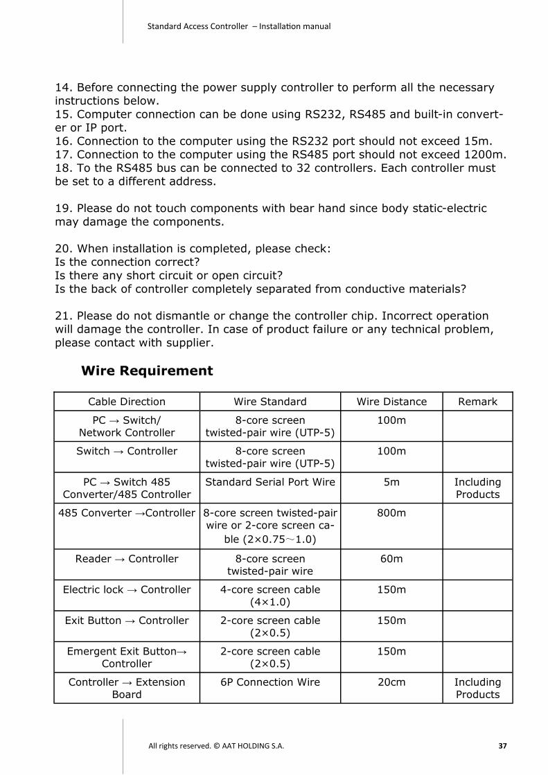
Wire Requirement
Cable Direction Wire Standard Wire Distance Remark
PC → Switch/
Network Controller
8-core screen
twisted-pair wire (UTP-5)
100m
Switch → Controller 8-core screen
twisted-pair wire (UTP-5)
100m
PC → Switch 485
Converter/485 Controller
Standard Serial Port Wire 5m Including
Products
485 Converter →Controller 8-core screen twisted-pair
wire or 2-core screen ca-
ble (2×0.75~1.0)
800m
Reader → Controller 8-core screen
twisted-pair wire
60m
Electric lock → Controller 4-core screen cable
(4×1.0)
150m
Exit Button → Controller 2-core screen cable
(2×0.5)
150m
Emergent Exit Button→
Controller
2-core screen cable
(2×0.5)
150m
Controller → Extension
Board
6P Connection Wire 20cm Including
Products

Standard Access Controller – Installation manual
All rights reserved. © AAT HOLDING S.A. 38
Trouble-Shooting
◆ Reader can not read card There are many reasons for this problem. User need to check:
1. When present card, is there any sound? Is the LED on? 2. Please check the connection. Is there any short-circuit or cut? Is your reader
output format correct? 3. Check the Register Card function of software. Is the card information re-
ceived? 4. Please check controller voltage DATA0 and DATA1. Voltage above 4V indicates
the reader dysfunctions; while lower than 4V indicates controller dysfunctions.
◆ Software can not connect with database 1. User is not authorized to write the database. (Go to WINDOWS/TEMP/, change
the read authorization to EVERYONE\everyone or install new system).
2. Module problem, user need to install again. 3. Operation system fails, re-install the system.
◆ Lock can not be closed
Connect the lock with12V power supply directly. If lock works, then test C and NC port and check whether there is any short-circuit (for fail-secure lock).
◆ Door can not be opened by presenting card
1. Make sure reader connection is correct. 2. Check whether the card number is in card record.
3. Check validity of the card. 4. For valid card, is the LED on and relay sounds when presenting card? If both
are ok, check lock connection and lock state.
5. If card is indicated as invalid, reasons are:
a) The card is illegal. The card is not registered and assigned by the software. User need to assign the card to access group.
b) The card is an expired temporary card. (Temporary card can be used within certain period only.)
c) You are using card+password mode. d) Your access group are not authorized to access this reader.
e) This reader needs First- card open (Any other card can open the door only after First-card is presented to the reader.)
f) This reader needs multi-card open. g) Card is not detected, present the card again.
h) Your card is damaged; make sure there is no fold, no burn and no magnetization.
I) The reader has anti-passback function. User can not present card on the same reader continuously.
j) This reader is used for attendance only.
k) System sets “All Day Forbidden”. I) “Remote control” is applied on this reader.

Standard Access Controller – Installation manual
All rights reserved. © AAT HOLDING S.A. 39
◆ Card-present time missed in the record
1. Database is not compatible. 2. Controller time is incorrect.
◆ Card-present Record disappears
1. Memory is damaged. 2. Record overflown.
3. History record is covered by new record. 4. Download record before upload. History record is cleared.
◆ TCP/IP converter problem
TCP/IP converter should be applied with Anson software. In case of data transmission error, user can adjust converter transmission delay.
◆ Fail to connect controller via RS 485 communication mode
Converter applied should be active and equipped with signal amplifier. In
addition, some types of USB-232 converter may not be compatible. Theoretically, communication distance of RS485 is 1200m, but its practical
distance is around 600m (because of interference, w i r e type, load capacity and so on).
It is not recommended to connect too many devices on a RS 485 bus. The prima quality connected is around 20 units. To connect more devices, user
can add a 120 ohm resistor between 485+ and 485-. Screen twisted-pair is the best choice. Moreover, user should also note that
the communication rate of software and hardware should be the same.
◆ Connection of RS485 communication Serial connection should be adopted.
◆ Time is incorrect and can not open the door
Validity of card is related to time. Due to component failure, aging and
interference etc., controller time may differ from PC time. It is recommended that administrator adjusts time periodically (every 2-3 months).
◆ Red light is still on after magnetic lock closed
This is caused by the mismatch or gap between lock surface and lock-core.
◆ Software password is forgotten If possible, please send us the database for recovery.
◆ Real-time monitoring does not work
Firstly, please edit an E-map and add some monitor position in the software. Secondly, ensure the connection between controller and software. For detailed
information, please refer to user manual.


![Architetture di nodi di commutazione ottici di tipo add ... · QPSK, e inserendo dei rilevatori coerenti.[7] Il baud rate di un segnale PDM-QPSK e un quarto del data rate (100 Gbps)](https://img.pdfslide.tips/doc/110x75/5e4254c9836158656a364003/architetture-di-nodi-di-commutazione-ottici-di-tipo-add-qpsk-e-inserendo-dei.jpg)