Embed Size (px)
Citation preview
www.lg.com
Please read this manual carefully before operating your set and retain it for future reference.
LV3***-U* LV5***-U
LED TVINSTALLATION MANUAL
ENGLISH
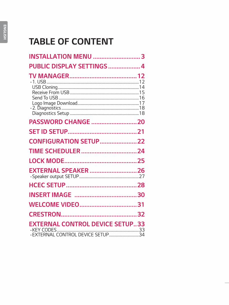
TABLE OF CONTENTINSTALLATION MENU ���������������������������� 3PUBLIC DISPLAY SETTINGS ������������������� 4TV MANAGER ����������������������������������������12
-1. USB ...................................................................................................12USB Cloning .......................................................................................14Receive From USB ..........................................................................15Send To USB ......................................................................................16Logo Image Download..................................................................17 -2. Diagnostics ...................................................................................18Diagnostics Setup ..........................................................................18
PASSWORD CHANGE ���������������������������20SET ID SETUP�����������������������������������������21CONFIGURATION SETUP ����������������������22TIME SCHEDULER ���������������������������������24LOCK MODE �������������������������������������������25EXTERNAL SPEAKER ����������������������������26
-Speaker output SETUP ................................................................27
HCEC SETUP ������������������������������������������28INSERT IMAGE �������������������������������������30WELCOME VIDEO ����������������������������������31CRESTRON ���������������������������������������������32EXTERNAL CONTROL DEVICE SETUP ��33
-KEY CODES ........................................................................................33 -EXTERNAL CONTROL DEVICE SETUP ................................34
3
ENGLISH
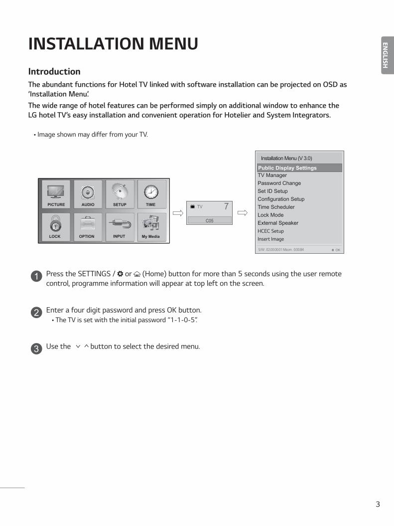
INSTALLATION MENUIntroductionThe abundant functions for Hotel TV linked with software installation can be projected on OSD as ‘Installation Menu’. The wide range of hotel features can be performed simply on additional window to enhance the LG hotel TV’s easy installation and convenient operation for Hotelier and System Integrators.
• Image shown may differ from your TV.
TV 7C05
PICTURE SETUP TIMEAUDIO
OPTIONLOCK My MediaINPUT
Installation Menu (V 3.0)
Public Display ModeTV ManagerPassword ChangeSet ID SetupConfiguration SetupTime SchedulerLock ModeExternal SpeakerHCEC SetupInsert Image
Public Display Settings
OKS/W : 02.00.00.01 Micom : 0.00.84
1 Press the SETTINGS / or (Home) button for more than 5 seconds using the user remote control, programme information will appear at top left on the screen.
2 Enter a four digit password and press OK button.• The TV is set with the initial password “1-1-0-5”.
3 Use the button to select the desired menu.
4
ENGLISH
Public Display Settings
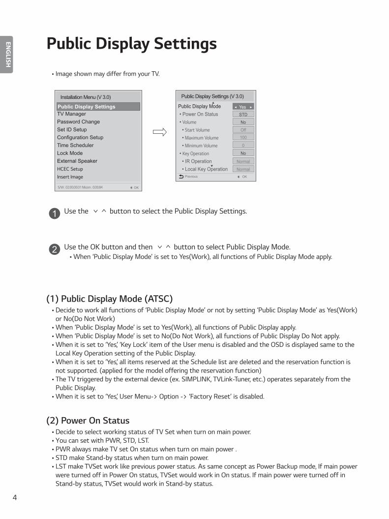
• Image shown may differ from your TV.
Public Display Settings (V 3.0)
Public Display Mode • Power On Status • Volume • Start Volume • Maximum Volume • Minimum Volume • Key Operation • IR Operation • Local Key Operation
OK
▼
▲
Previous
◄ Yes ►
Normal
Normal
No
0
100Off
No
STD
Installation Menu (V 3.0)
Public Display ModeTV ManagerPassword ChangeSet ID SetupConfiguration SetupTime SchedulerLock ModeExternal SpeakerHCEC SetupInsert Image
Public Display Settings
OKS/W : 02.00.00.01 Micom : 0.00.84
1 Use the button to select the Public Display Settings.
2 Use the OK button and then button to select Public Display Mode.• When ‘Public Display Mode’ is set to Yes(Work), all functions of Public Display Mode apply.
(1) Public Display Mode (ATSC)• Decide to work all functions of ‘Public Display Mode’ or not by setting ‘Public Display Mode’ as Yes(Work)
or No(Do Not Work) • When ‘Public Display Mode’ is set to Yes(Work), all functions of Public Display apply.• When ‘Public Display Mode’ is set to No(Do Not Work), all functions of Public Display Do Not apply.• When it is set to ‘Yes’, ‘Key Lock’ item of the User menu is disabled and the OSD is displayed same to the
Local Key Operation setting of the Public Display.• When it is set to ‘Yes’, all items reserved at the Schedule list are deleted and the reservation function is
not supported. (applied for the model offering the reservation function)• The TV triggered by the external device (ex: SIMPLINK, TVLink-Tuner, etc.) operates separately from the
Public Display.• When it is set to ‘Yes’, User Menu-> Option -> ‘Factory Reset’ is disabled.
(2) Power On Status• Decide to select working status of TV Set when turn on main power.• You can set with PWR, STD, LST.• PWR always make TV set On status when turn on main power .• STD make Stand-by status when turn on main power.• LST make TVSet work like previous power status. As same concept as Power Backup mode; If main power
were turned off in Power On status, TVSet would work in On status. If main power were turned off in Stand-by status, TVSet would work in Stand-by status.
5
ENGLISH
(3) Volume (0 ≤ Min ≤ Start ≤ Max ≤ 100)• Decide to apply volume policy of ‘Start Volume’, ‘Maximum Volume’ and ‘Minimum Volume’
as Yes(Work) or No(Do Not Work).
(3-1) Start VolumeThis entry sets the start volume level when is power on.
• The level is specified as a number between minimum volume to maximum value. (Min ≤ Start ≤ Max)
• The default setting is ‘Off’ (disabled).• When enabled, if the value is lower then the minimum specified in the minimum volume entry, the
minimum volume entry must be used.• When enabled, if the value is larger then the maximum specified in the maximum volume entry,
the maximum volume value must be used. • Access to a volume in ‘On Timer’ must be fixed to start volume when ‘Hotel Mode Operation’ (Yes)
and ‘Start Volume’ (Off, 0 ~ 100) were set simultaneously.
(3-2) Maximum VolumeThis entry sets the maximum volume level the set. The level is specified as a number between ‘Minimum Volume’ to 100. (Min ≤ Max ≤ 100)
• If the command volume up to higher than maximum volume’ is received, that should be ignored.• The default value is 100.
(3-3) Minimum Volume This entry sets the minimum volume level the set will produce.
• The level is specified as a number between 0 to ‘Maximum Volume’. (0 ≤ Min ≤ Max)• If the command volume down to lower than minimum volume is received, that should be ignored.• The default value is 0.
(4) Key Operation• Manage key usability of Local(Front) Key and Remote Control. When selected to ‘Yes’, following ‘IR
Operation’ and ‘Local Key Operation’ will be worked by below.
(4-1) IR OperationDecide whether work the LG remote control or not.
• Able to set Normal, Use PWR Only, Block All• When ‘IR Operation’ is set to Block All, all normal remote keys don’t work. Use PWR Only (Block
except power) makes block all remote keys except power key.• Although ‘IR Operation’ value is Use PWR Only or Block All.• It can work in ‘Service mode’. (In-Start, In-Stop, Power-Only, ADJ, Hotel-Mode,
Hotel-Mode-Ready, P-Check, S-check, In-Time, FMode-Init, FMode-Start, FMode-AV, FMode-F1)
• Menu key action to enter the ‘Installation Menu’ and key action with ‘Special menu(In-Start / EZ-Adjust …)’ are still available.
• When ‘IR Operation’ is set to Normal (Work), all remote keys are available.
6
ENGLISH
(4-2) Local Key OperationDecide to operate ‘Local/Front Key’ working behavior by setting ‘Local Key Operation’ as Normal, Block All. (* 40LV3**H series use Normal, Use PWR Only, Block All.)
• When ‘Local Key Operation’ is set to Block All, all local keys don’t work. (If value is Use PWR Only, it blocks all local keys except power key.)
• When ‘Local Key Operation’ is set to Normal, all local key are available.
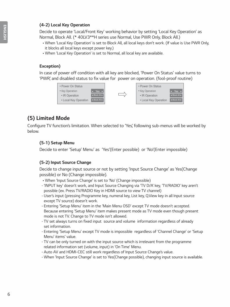
Exception) In case of power off condition with all key are blocked, ‘Power On Status’ value turns to ‘PWR’, and disabled status to fix value for power on operation. (fool-proof routine)
• Power On Status • Key Operation • IR Operation • Local Key Operation
◄ Yes ►◄ Block All ►
◄ Block All ►
• Power On Status • Key Operation • IR Operation • Local Key Operation
◄ Yes ►◄ Block All ►
◄ Block All ►
(5) Limited ModeConfigure TV function’s limitation. When selected to ‘Yes’, following sub-menus will be worked by below.
(5-1) Setup MenuDecide to enter ‘Setup’ Menu’ as ‘Yes’(Enter possible) or ‘No’(Enter impossible)
(5-2) Input Source ChangeDecide to change input source or not by setting ‘Input Source Change’ as Yes(Change possible) or No (Change impossible).
• When ‘Input Source Change’ is set to ‘No’ (Change impossible) - ‘INPUT key’ doesn’t work, and Input Source Changing via ‘TV D/A’ key, ‘TV/RADIO’ key aren’t possible (ex. Press TV/RADIO Key in HDMI source to view TV channel) - User’s input (pressing Programme key, numeral key, List key, Q.View key in all Input source except TV source) doesn’t work. - Entering ‘Setup Menu’ item in the ‘Main Menu OSD’ except TV mode doesn’t accepted. Because entering ‘Setup Menu’ item makes present mode as TV mode even though present mode is not TV. Change to TV mode isn’t allowed. - TV set always turns on fixed input source and volume information regardless of already set information. - Entering ‘Setup Menu’ except TV mode is impossible regardless of ‘Channel Change’ or ‘Setup Menu’ items’ value. - TV can be only turned on with the input source which is irrelevant from the programme related information set (volume, input) in ‘On Time’ Menu. - Auto AV and HDMI-CEC still work regardless of Input Source Change’s value. - When ‘Input Source Change’ is set to Yes(Change possible), changing input source is available.
7
ENGLISH
(5-3) Channel ChangeDecide to change channel or not by setting ‘Channel Change’ as ‘Yes’(Change Possible) or ‘No’(Change Impossible) when present source is TV.
• When ‘Channel Change’ is set to No (Change Impossible) - Channel Key, Numeral Key, List Key, Q.View Key don’t work and entering ‘Channel Menu’ in the Main Menu OSD is impossible. - ‘Channel’ item in ‘On Time’ menu will be fixed. - Entering ‘Setup Menu’ in the ‘Main Menu’ OSD is impossible regardless of ‘Setup Menu’ item.• When ‘Channel Change’ is set to Yes(Change Possible), ‘Channel Key’, ‘Numeric Key’, ‘List Key’,
‘Q.View’ Key does work and entering ‘Channel Menu’ in the Main Menu OSD is possible.
(5-4) Menu DisplayFunction to decide whether work with menu (including relevant menus too) of control key (Yes – Enter possible) or not (No – Enter Impossible).
• Although select No(Enter impossible), the action that press a Menu button for 5 seconds to enter ‘Installation Menu’ is available.
• When select Yes(Enter possible), Menu works.
(5-5) OSD Display Decide to display OSD or not by setting ‘OSD Display’ as Yes(Display) or No(Do not Display).
• When ‘OSD Display’ is set to ‘No’(Do not Display), all OSD is not displayed except some exception.• Although select ‘No’ (Do not Display), the action that press a Menu button for 5 seconds to
enter ‘Installation Menu’ and entering service menu are available. (In-Start, Power-Only, Adjust, Installation Menu …)
(5-6) System Provider Mode ‘System Provider Mode’ allows access to the menu system from the front panel or remote control but access is controlled as follows:
• When value is ‘Yes’, Accessible Items on the menu system, others are not permissible. - Input select screens - Sleep timer - Aspect Ratio - Closed Caption - ‘Lock’ / ‘My Media’ / ‘Network’ / ‘Customer Support’ Menu• ‘Q.menu’, which is related to ‘Setup’ Menu, is not accessible.• If the channel map is empty, ‘Auto-tuning’ guide dialog should be blocked by pressing ‘List’, ‘Fav’,
‘CH+’ (Page up), ‘CH-’ (Page down) keys.
8
ENGLISH
(6) Power ManagementThe Power Management feature will turn off the television receiver if no input control command is received from either the Local or IR Key within a selected hours.
• Activity on either of these inputs shall restart the ‘Power Management’ timer and check key time interval again.
• This entry can be set to a value which is corresponding to the desired hours (1 to 7).• Default value is ‘Off(disabled)’.• TV should off and on after apply this setting.
(7) DTV Channel UpdateIt is a mode to set whether to update DTV channel information automatically or not.
• When DTV Channel Update is set to ’Auto’, the function to update TV’s programme map according to DTV channel’s stream information
• DTV Channel Update is set to ‘Manual’, the function to keep TV’s channel map even though DTV programme’s information is changed.
(8) Power On DefaultSet the input source or channel to display and. A/V settings when turn on power in AC Power On or Stand-by status.
(8-1) Input Source Set whether it is turned on by the set input source or by the last stored input source.
• It is turned on by the Last Memory Input if the Input source is turned off.• It is turned on by the Last Pr. If the Input source is turned off and the last memory Input is the RF.• The available Input Source values should be rotated.• If both the Input source and the ‘On Time’ menu are set, the Input source takes the priority.• When the Input source is changed to the TV, Programme menu is available.• When the Input source is changed to the ATV, the Program No. is set to 0. (If the channel map
structure does not support this, it depends on model’s channel handling.)• Access to an input source item and a channel in ‘On Timer’ menu must be disabled when Power On
Default is activated.
(8-2) Tune Mode Tune the selected start channel with physical or virtual method. Usually, digital channel uses virtual channel and analog channel uses physical channel.
9
ENGLISH
(8-3) MajorSelect major part of start channel number if Input source value is TV. (in case of ATV, it means physical channel number.)
(8-4) MinorSelect minor part of start channel number if Input source value is TV.
(8-5) A/V SettingIf ‘A/V Setting’ is changed from ‘No’ to ‘Yes’, parameters that are set before entering ‘Installation Menu’ are applied whenever turn on power.
• Following Parameters are applied to basic. - Picture section - PSM mode, Picture Data (Contrast, Brightness, Color, Sharpness, Tint) - Sound section - SSM mode, Sound Data (Balance, Equalizer Data) - AVL (Auto Volume Level) and Language, Teletext language, ARC Data. Except these, other parameters are applied differently according to the TV-Set.
(8-6) Aspect RatioThe aspect ratio determines the default aspect ratio that the set returns to on power up.
• The modes are as follows: - Aspect ratio = “Disable(0)” stays at previous state, same as consumer model. - Aspect ratio = “Set by Program(1)” - Aspect ratio = “4:3 ratio (2)” - Aspect ratio = “16:9 ratio (3)”• If enabled, upon power up the television resets the aspect ratio to the specified state regardless
of how the user has previously changed the aspect ratio. Set by Program.
10
ENGLISH
(9) Aux Source SettingThe Auxiliary (Input) Source Setting feature will enable or disable for each external input. When ‘Aux Source Setting’ is set to Yes(Work), the RJP or HDMI-CEC / HTNG will not operate
(9-1) Input Source• Available Input Source List
(9-2) Setting• Decide whether selected ‘Input Source’ is usable (Enable) or not (Disable).• User cannot disable the current input’s ‘Aux Source Setting’.
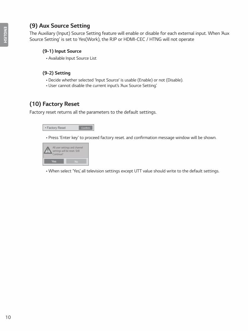
(10) Factory ResetFactory reset returns all the parameters to the default settings.
• Factory Reset Confirm
• Press ‘Enter key’ to proceed factory reset. and confirmation message window will be shown.
All user settings and channel settings will be reset. Still Continue?
Yes No
• When select ‘Yes’, all television settings except UTT value should write to the default settings.

11
ENGLISH
Public Display Settings
Item Enable Disable InitialPublic Display Settings Yes No NoPower On Status - - *STDVolume Yes No No
Start Volume Off, Minimum Volume ~ Maximum Volume OffMaximum Volume Minimum Volume ~ 100 100Minimum Volume 0 ~ Maximum Volume 0
Key Operation Yes No NoIR Operation Normal / Use PWR Only / Block All NormalLocal Key Operation Normal / Use PWR Only / Block All Normal
Limited Mode Yes No NoSetup Menu Yes No YesInput Source Change Yes No YesChannel Change Yes No YesMenu Display Yes No YesOSD Display Yes No YesSystem Provider Mode Yes No No
Power Management Off, 1 ~ 7 OffDTV Channel Update Auto Manual AutoPower On Default Yes No NoInput Source Off, ATV, DTV, ... OffTune Mode Physical Virtual PhysicalMajor 2 ~ 69(TV, DTV, CATV, CADTV) 2Minor 1 ~ 999 (DTV, CADTV) 1A/V Setting Yes No NoAspect Ratio Disable / Set By Program / 4:3 / 16:9 Disable
Public Display Settings
Item Enable Disable InitialAux Source Setting Yes No No
Input Source Aux Input(AV1 ~ MAX_INPUT) AV1Settng Enable Disable Enable
Factory Reset Confirmation window (Yes / No)
12
ENGLISH
TV Manager
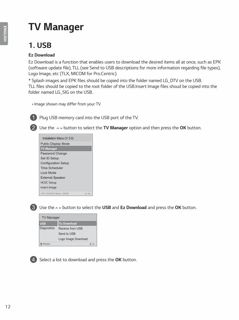
1� USBEz DownloadEz Download is a function that enables users to download the desired items all at once, such as EPK (software update file), TLL (see Send to USB descriptions for more information regarding file types), Logo Image, etc (TLX, MICOM for Pro:Centric).* Splash images and EPK files should be copied into the folder named LG_DTV on the USB. TLL files should be copied to the root folder of the USB.Insert Image files shoud be copied into the folder named LG_SIG on the USB.
• Image shown may differ from your TV.
1 Plug USB memory card into the USB port of the TV.
2 Use the button to select the TV Manager option and then press the OK button.
Installation Menu (V 3.0)
Public Display Mode
Password ChangeSet ID SetupConfiguration SetupTime SchedulerLock ModeExternal SpeakerHCEC SetupInsert Image
TV Manager
OKS/W : 02.00.00.01 Micom : 0.00.84
3 Use the button to select the USB and Ez Download and press the OK button.
TV Manager
Ez Download
Receive from USBSend to USBLogo Image Download
Diagnostics
OKPrevious
USB
4 Select a list to download and press the OK button.
13
ENGLISH
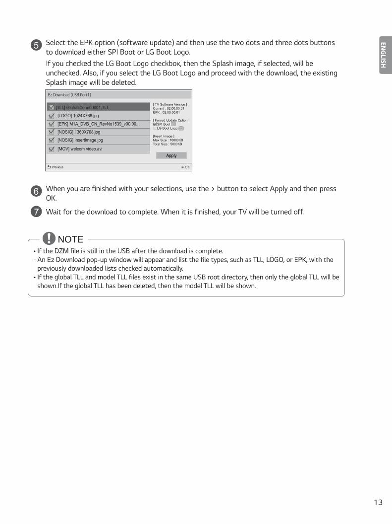
5 Select the EPK option (software update) and then use the two dots and three dots buttons to download either SPI Boot or LG Boot Logo.If you checked the LG Boot Logo checkbox, then the Splash image, if selected, will be unchecked. Also, if you select the LG Boot Logo and proceed with the download, the existing Splash image will be deleted.
Ez Download (USB Port1)
[TLL] GlobalClone00001.TLL
OKPrevious
[LOGO] 1024X768.jpg
[ TV Software Version ]Current : 02.00.00.01EPK : 02.00.00.01
[ Forced Update Option ] SPI Boot LG Boot Logo
[Insert Image ]Max Size : 10000KBTotal Size : 5000KB
Apply
[EPK] M1A_DVB_CN_RevNo1539_v00.00...
[NOSIG] 1360X768.jpg
[NOSIG] Insertlmage.jpg
[MOV] welcom video.avi
6 When you are finished with your selections, use the > button to select Apply and then press OK.
7 Wait for the download to complete. When it is finished, your TV will be turned off.
NOTE• If the DZM file is still in the USB after the download is complete: - An Ez Download pop-up window will appear and list the file types, such as TLL, LOGO, or EPK, with the previously downloaded lists checked automatically.
• If the global TLL and model TLL files exist in the same USB root directory, then only the global TLL will be shown.If the global TLL has been deleted, then the model TLL will be shown.

14
ENGLISH
USB Cloning
An Installer can quickly set up and clone multiple TV sets at a property. These cloned TVs will all have the same Master TV Setup: Public Display Mode Installation Menu settings, User A/V settings and the Channel Map. This newer procedure significantly decreases the installation time that would be necessary if the standard RS-232C method were used instead.
Introduction(1) Overview USB Cloning Procedure
• Commercial TVs have the capability to support cloning internal TV data and programme information with an external clone device called “USB Cloning”, in order to copy TV data accurately and quickly. The clone internal functions use slightly different internal processes for the two types of commercial TVs. However, the UI of cloning feature remains the same in both. Regarding the demands over the current cloning feature for quicker clonin g, better portability and etc, we would like to announce the cloning process via USB port, named as USB Cloning. USB cloning process is divided into 2 main processes. One is writing the previously saved TV data into the TV, and one another is reading of current TV data into USB memory card. To avoid any confusion due to the words, it is clearly specified as “Receive from USB” and “Send to USB” in the whole process.
(2) Data To Be Cloned • The data cloned are the same data cloned by previous USB Cloning. Details are explained in the following: - 1. TV data includes:
A. Installer Menu settings B. Main menu settings (Audio, Picture etc)
- 2. Analog / Digital Channel information includes: A. Channel numbers B. Channel label C. Channel attributes including channel type, skipping status and etc.
(3) Input Source• The user needs a USB memory card with FAT formatted to make successive cloning via USB port. A USB
memory card size more than 128 Mega Bytes and less than 4 Giga Bytes is recommended.
NOTE• Currently, support the preceding USB file system for FAT file format only. Other file formats including
NTFS is not currently supported. Microsoft Windows officially supports FAT for the USB memory card.
15
ENGLISH
Receive From USB
• Image shown may differ from your TV.
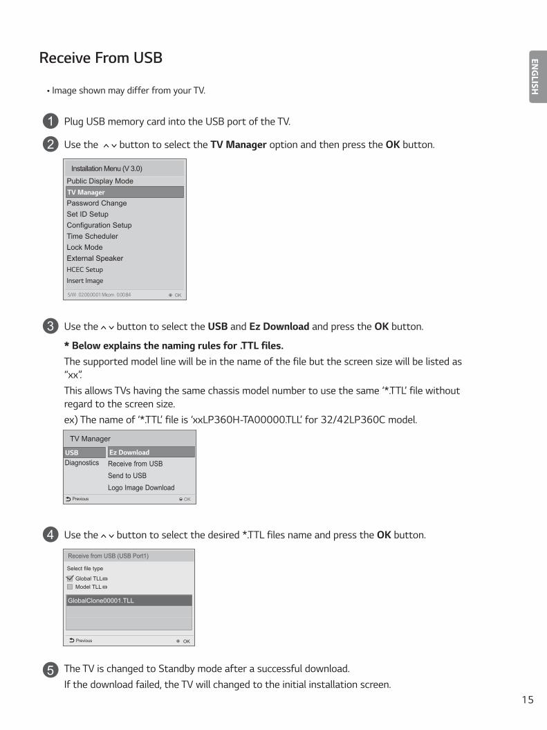
1 Plug USB memory card into the USB port of the TV.
2 Use the button to select the TV Manager option and then press the OK button.
Installation Menu (V 3.0)
Public Display Mode
Password ChangeSet ID SetupConfiguration SetupTime SchedulerLock ModeExternal SpeakerHCEC SetupInsert Image
TV Manager
OKS/W : 02.00.00.01 Micom : 0.00.84
3 Use the button to select the USB and Ez Download and press the OK button.
* Below explains the naming rules for .TTL files.The supported model line will be in the name of the file but the screen size will be listed as “xx”.This allows TVs having the same chassis model number to use the same ‘*.TTL’ file without regard to the screen size.ex) The name of ‘*.TTL’ file is ‘xxLP360H-TA00000.TLL’ for 32/42LP360C model.
TV Manager
Ez Download
Receive from USBSend to USBLogo Image Download
Diagnostics
OKPrevious
USB
4 Use the button to select the desired *.TTL files name and press the OK button.
Receive from USB (USB Port1)
GlobalClone00001.TLL
OKPrevious
Select file type
Global TLL Model TLL
5 The TV is changed to Standby mode after a successful download.If the download failed, the TV will changed to the initial installation screen.
16
ENGLISH
Send To USB
• Image shown may differ from your TV.
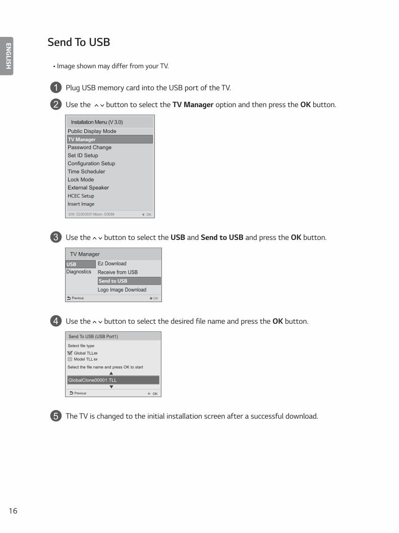
1 Plug USB memory card into the USB port of the TV.
2 Use the button to select the TV Manager option and then press the OK button.
Installation Menu (V 3.0)
Public Display Mode
Password ChangeSet ID SetupConfiguration SetupTime SchedulerLock ModeExternal SpeakerHCEC SetupInsert Image
TV Manager
OKS/W : 02.00.00.01 Micom : 0.00.84
3 Use the button to select the USB and Send to USB and press the OK button.
TV Manager
Ez DownloadReceive from USBSend to USB
Logo Image Download
Diagnostics
OKPrevious
USB
4 Use the button to select the desired file name and press the OK button.
Send To USB (USB Port1)
GlobalClone00001.TLL
OKPrevious
Select file type
Global TLL Model TLL
▲
▲
Select the file name and press OK to start
5 The TV is changed to the initial installation screen after a successful download.
17
ENGLISH
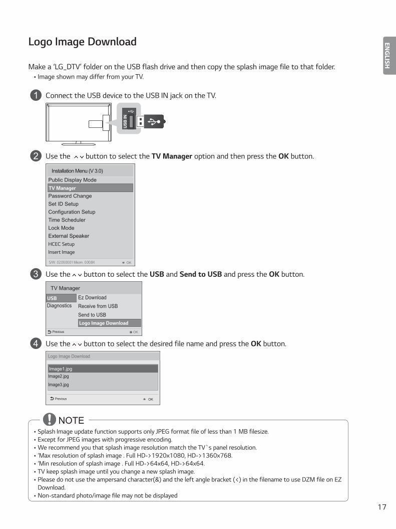
Logo Image Download
Make a ‘LG_DTV’ folder on the USB flash drive and then copy the splash image file to that folder.• Image shown may differ from your TV.
1 Connect the USB device to the USB IN jack on the TV.AV
(RGB)
/DVI IN1 2
COMPONENTIN
RGB IN (PC)SPEAKEROUT ANTENNA/
CABLE IN
OPTICALAUDIO OUT
AUDIO IN(COMPONENT/RGB/DVI)
RS-232C IN(CONTROL & SERVICE)
H/P O
UT IN
3US
B IN
PCM
CIA
CARD
SLO
T
2 Use the button to select the TV Manager option and then press the OK button.
Installation Menu (V 3.0)
Public Display Mode
Password ChangeSet ID SetupConfiguration SetupTime SchedulerLock ModeExternal SpeakerHCEC SetupInsert Image
TV Manager
OKS/W : 02.00.00.01 Micom : 0.00.84
3 Use the button to select the USB and Send to USB and press the OK button.
TV Manager
Ez DownloadReceive from USBSend to USBLogo Image Download
Diagnostics
OKPrevious
USB
4 Use the button to select the desired file name and press the OK button.Logo Image Download
Image1.jpg
OKPrevious
Image2.jpg
Image3.jpg
NOTE• Splash Image update function supports only JPEG format file of less than 1 MB filesize.• Except for JPEG images with progressive encoding.• We recommend you that splash image resolution match the TV`s panel resolution.• ‘Max resolution of splash image : Full HD->1920x1080, HD->1360x768.• ‘Min resolution of splash image : Full HD->64x64, HD->64x64.• TV keep splash image until you change a new splash image.• Please do not use the ampersand character(&) and the left angle bracket (<) in the filename to use DZM file on EZ
Download.• Non-standard photo/image file may not be displayed
18
ENGLISH
2� Diagnostics
Diagnostics Setup
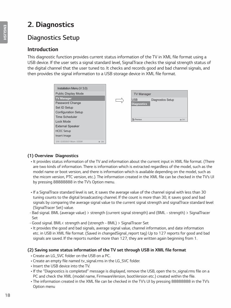
IntroductionThis diagnostic function provides current status information of the TV in XML file format using a USB device. If the user sets a signal standard level, SignalTrace checks the signal strength status of the digital channel that the user tuned to. It checks and records good and bad channel signals, and then provides the signal information to a USB storage device in XML file format.
Diagnostics SetupUSB
OKPrevious
Diagnostics
TV Manager
Installation Menu (V 3.0)
Public Display Mode
Password ChangeSet ID SetupConfiguration SetupTime SchedulerLock ModeExternal SpeakerHCEC SetupInsert Image
TV Manager
OKS/W : 02.00.00.01 Micom : 0.00.84
(1) Overview Diagnostics• It provides status information of the TV and information about the current input in XML file format. (There
are two kinds of information. There is information which is extracted regardless of the model, such as the model name or boot version, and there is information which is available depending on the model, such as the micom version, PTC version, etc.). The information created in the XML file can be checked in the TV’s UI by pressing 88888888 in the TV’s Option menu.
• If a SignalTrace standard level is set, it saves the average value of the channel signal with less than 30 tuning counts to the digital broadcasting channel. If the count is more than 30, it saves good and bad signals by comparing the average signal value to the current signal strength and signalTrace standard level (SignalTracer Set) value.
- Bad signal: BML (average value) > strength (current signal strength) and (BML - strength) > SignalTracer Set - Good signal: BML< strength and (strength - BML) > SignalTracer Set• It provides the good and bad signals, average signal value, channel information, and date information
etc. in USB in XML file format. (Saved in changedSignal_report tag) Up to 127 reports for good and bad signals are saved. If the reports number more than 127, they are written again beginning from 1.
(2) Saving some status information of the TV set through USB in XML file format• Create an LG_SVC folder on the USB on a PC.• Create an empty file named tv_signal.rms in the LG_SVC folder.• Insert the USB device into the TV.• If the “Diagnostics is completed” message is displayed, remove the USB, open the tv_signal.rms file on a
PC and check the XML (model name, FirmwareVersion, bootVersion etc.) created within the file.• The information created in the XML file can be checked in the TV’s UI by pressing 88888888 in the TV’s
Option menu
19
ENGLISH
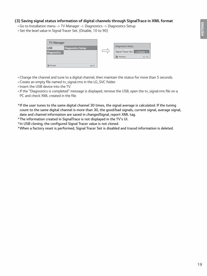
(3) Saving signal status information of digital channels through SignalTrace in XML format• Go to Installation menu -> TV Manager -> Diagnostics -> Diagnostics Setup • Set the level value in Signal Tracer Set. (Disable, 10 to 90)
USB
OKPrevious
Diagnostics
TV Manager
Diagnostics SetupSignal Tracer Set ◄ Disable ►
Diagnostics Setup
OKPrevious
• Change the channel and tune to a digital channel, then maintain the status for more than 5 seconds.• Create an empty file named tv_signal.rms in the LG_SVC folder.• Insert the USB device into the TV.• If the “Diagnostics is completed” message is displayed, remove the USB, open the tv_signal.rms file on a
PC and check XML created in the file.
* If the user tunes to the same digital channel 30 times, the signal average is calculated. If the tuning count to the same digital channel is more than 30, the good/bad signals, current signal, average signal, date and channel information are saved in changedSignal_report XML tag.
* The information created in SignalTrace is not displayed in the TV's UI.* In USB cloning, the configured Signal Tracer value is not cloned.* When a factory reset is performed, Signal Tracer Set is disabled and traced information is deleted.
20
ENGLISH
Password Change
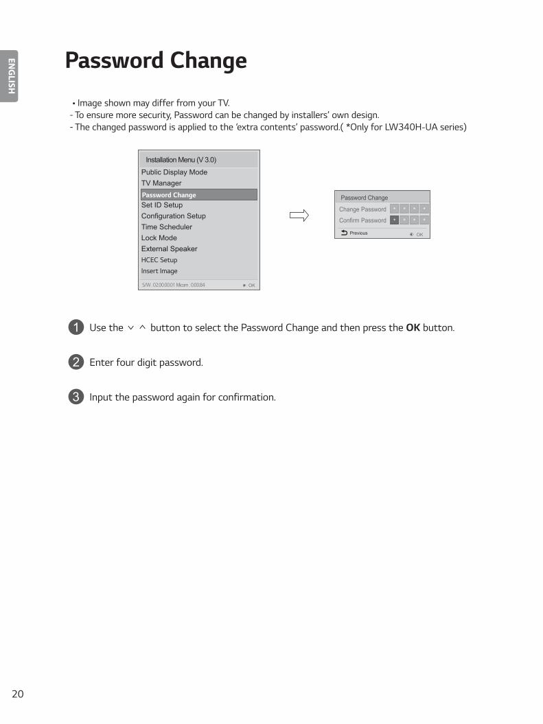
• Image shown may differ from your TV. - To ensure more security, Password can be changed by installers’ own design. - The changed password is applied to the ‘extra contents’ password.( *Only for LW340H-UA series)
Change Password
Confirm Password
Password Change
* * * *
* * * *
OKPrevious
Installation Menu (V 3.0)
Public Display ModeTV ManagerPassword ChangeSet ID SetupConfiguration SetupTime SchedulerLock ModeExternal SpeakerHCEC SetupInsert Image
Password Change
OKS/W : 02.00.00.01 Micom : 0.00.84
1 Use the button to select the Password Change and then press the OK button.
2 Enter four digit password.
3 Input the password again for confirmation.
21
ENGLISH
Set ID Setup
OK
Set ID Lock
Set ID
◄ Yes ►
1
Previous
Set ID Setup
OK
Installation Menu (V 3.0)
Public Display ModeTV ManagerPassword ChangeSet ID SetupConfiguration SetupTime SchedulerLock ModeExternal SpeakerHCEC SetupInsert Image
Set ID Setup
OKS/W : 02.00.00.01 Micom : 0.00.84
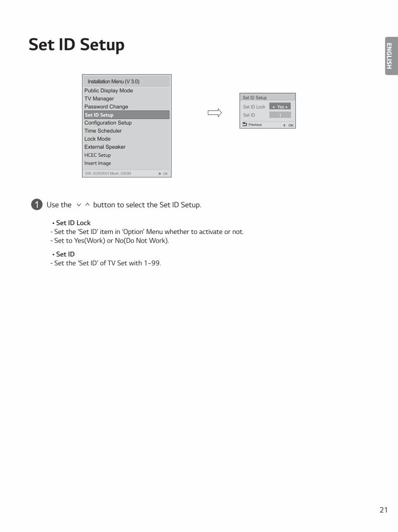
1 Use the button to select the Set ID Setup.
• Set ID Lock - Set the ‘Set ID’ item in ‘Option’ Menu whether to activate or not. - Set to Yes(Work) or No(Do Not Work).
• Set ID - Set the ‘Set ID’ of TV Set with 1~99.
22
ENGLISH
Configuration Setup
• Image shown may differ from your TV.
Installation Menu (V 3.0)
Public Display ModeTV ManagerPassword ChangeSet ID Setup
Time SchedulerLock ModeExternal SpeakerHCEC SetupInsert Image
Configuration Setup
OKS/W : 02.00.00.01 Micom : 0.00.84
Number of RCU
Splash Offset Time
USB Auto Playback
15Min Auto Off
Auto Sensing
Forced DVI Audio
Screen Saver Cube
Wake On Lan
Configuration Setup
Photo
Disable
To Set
Off
Yes
Previous OK
0
◄ Off ►
Yes
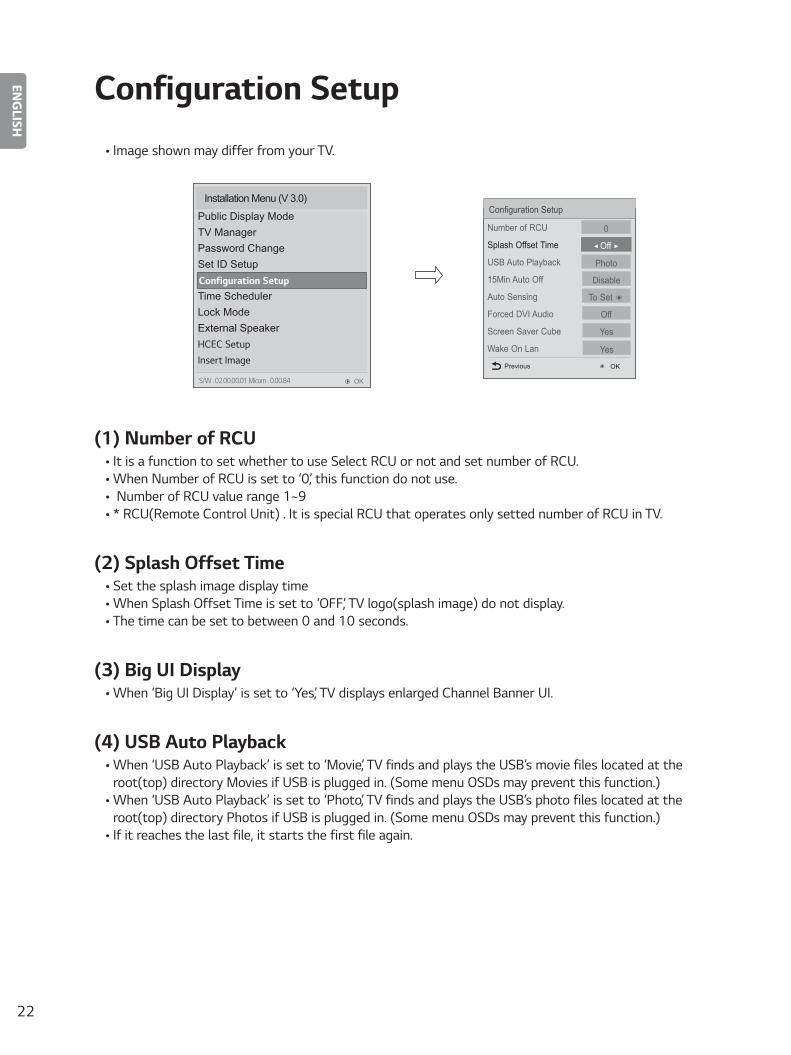
(1) Number of RCU• It is a function to set whether to use Select RCU or not and set number of RCU.• When Number of RCU is set to ‘0’, this function do not use.• Number of RCU value range 1~9• * RCU(Remote Control Unit) : It is special RCU that operates only setted number of RCU in TV.
(2) Splash Offset Time• Set the splash image display time• When Splash Offset Time is set to ‘OFF’, TV logo(splash image) do not display.• The time can be set to between 0 and 10 seconds.
(3) Big UI Display• When ‘Big UI Display’ is set to ‘Yes’, TV displays enlarged Channel Banner UI.
(4) USB Auto Playback• When ‘USB Auto Playback’ is set to ‘Movie’, TV finds and plays the USB’s movie files located at the
root(top) directory Movies if USB is plugged in. (Some menu OSDs may prevent this function.)• When ‘USB Auto Playback’ is set to ‘Photo’, TV finds and plays the USB’s photo files located at the
root(top) directory Photos if USB is plugged in. (Some menu OSDs may prevent this function.)• If it reaches the last file, it starts the first file again.
23
ENGLISH
(5) 15Min Auto Off• When ‘15Min Auto Off’ is set to ‘Enable’, TV will turn off if there is no signal in 15Min.
(6) Auto Sensing• -If ‘Auto Sensing’ is set to ‘ ', the input is automatically switched when the input signal that you
set to ‘ON’ is received.• If ‘Auto Sensing’ is set to ‘Disable’, the input is not switched when the input signal is received.• If SIMPLINK is set to On, HDMI is automatically set to Disable and can not work.• If the signal is removed while Auto Sensing (automatic input switch) is enabled, the input returns to the
previous setting. • If the several inputs are connected by enabling Auto Sensing and the automatic input switch is performed
several times, the input returns to the previous setting only for the last input and does not repeat the operation for the rest.
• For the AV input connected using the euro scart cable, Auto Sensing does not work for the TV input because the Auto AV function is enabled.(For other inputs, Auto Sensing works normally.)
(7) Forced DVI Audio• When Forced DVI Audio is selected, the audio signal from the HDMI port will be transmitted through the
RGB, AV, or Audio In #1 component ports. • The video signal will be transmitted through HDMI to be displayed on the screen in standard quality.• For the audio signal, the priority order is the RGB -> AV -> Audio In component ports.
(8) Screen Saver Cube• When ‘Screen Saver Cube’ is set to ‘No’, TV will do not display LG Screen Cube.
(9) WOL(Wake On Lan)*Depending upon model
• If Set to “YES”, User can turn on the TV by using LAN network.• Only Magic Packet is valid.• If TV get a magic packet that include TV’s mac address, TV will be turned on.• TV will sustain WOL setting value, although user unplug the TV.
(10) Video Mute• When ‘Video Mute’ is set to ‘Yes’, for Blank.
(11) Noise Mute• When ‘Noise Mute’ is set to ‘Yes’, audio mutes when no signal is present.
24
ENGLISH
Time Scheduler
Time Scheduler
On Timer◄ On ►
Time Scheduler
OK
Off Timer
Previous
Installation Menu (V 3.0)
Public Display ModeTV ManagerPassword ChangeSet ID SetupConfiguration SetupTime schedulerLock ModeExternal SpeakerHCEC SetupInsert Image
Time Scheduler
OKS/W : 02.00.00.01 Micom : 0.00.84
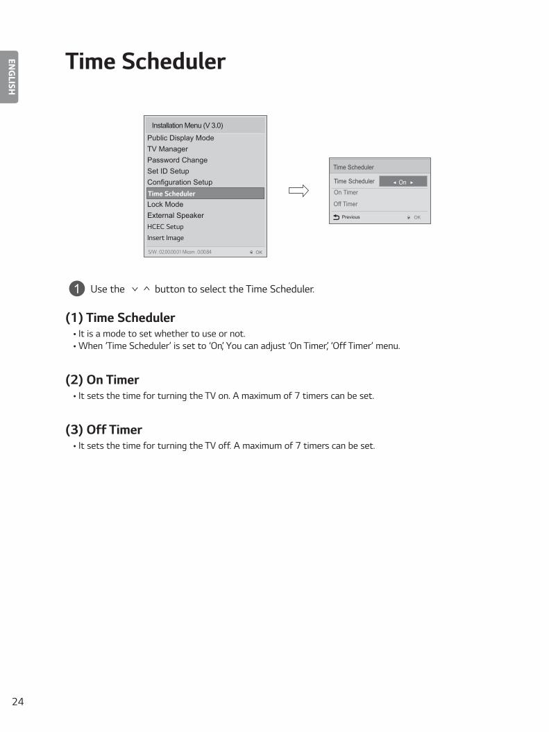
1 Use the button to select the Time Scheduler.
(1) Time Scheduler• It is a mode to set whether to use or not. • When ‘Time Scheduler’ is set to ‘On’, You can adjust ‘On Timer’, ‘Off Timer’ menu.
(2) On Timer• It sets the time for turning the TV on. A maximum of 7 timers can be set.
(3) Off Timer• It sets the time for turning the TV off. A maximum of 7 timers can be set.
25
ENGLISH
Lock Mode
Installation Menu (V 3.0)
Public Display ModeTV ManagerPassword ChangeSet ID SetupConfiguration SetupTime scheduler
External SpeakerHCEC SetupInsert Image
Lock Mode
OKS/W : 02.00.00.01 Micom : 0.00.84
Data Service
USB
◄ Enable ►
Enable
Previous
Lock Mode
OK
Factory Reset Enable
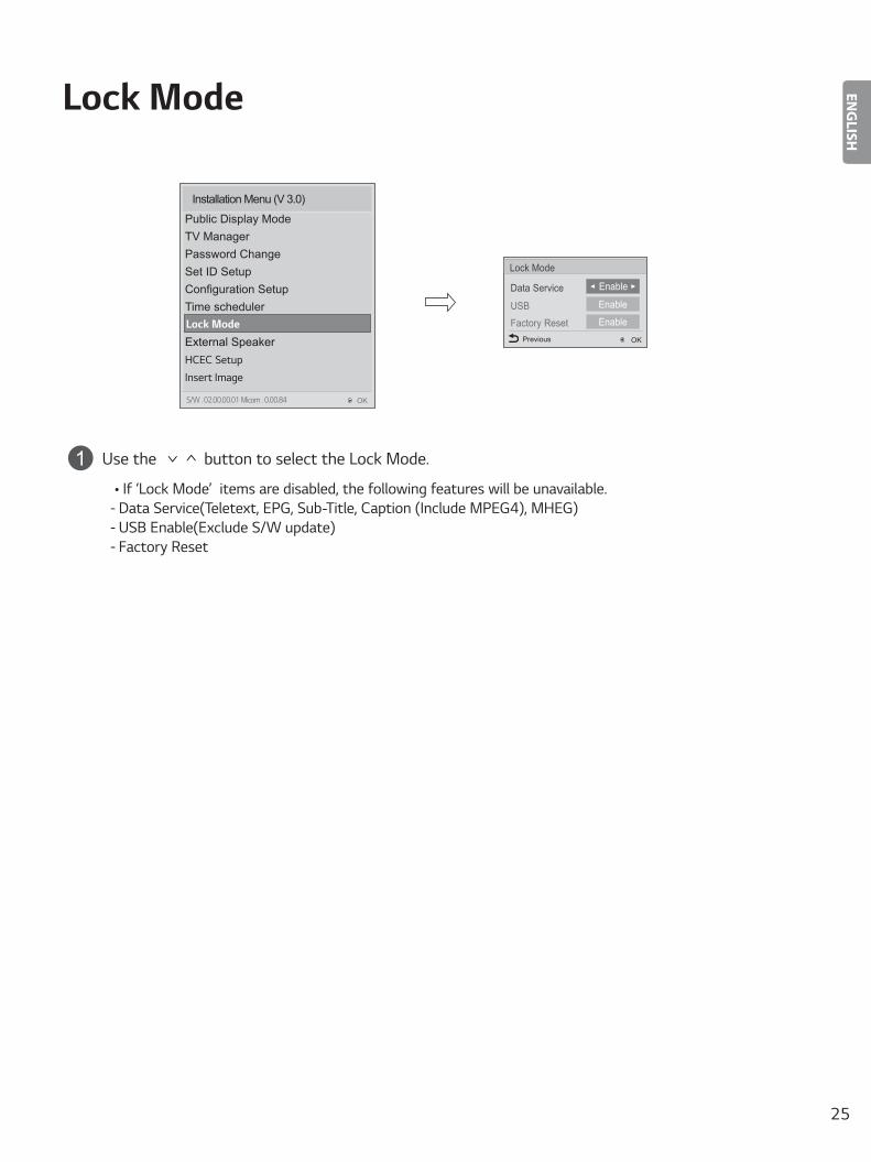
1 Use the button to select the Lock Mode.
• If ‘Lock Mode’ items are disabled, the following features will be unavailable. - Data Service(Teletext, EPG, Sub-Title, Caption (Include MPEG4), MHEG) - USB Enable(Exclude S/W update) - Factory Reset

26
ENGLISH
External Speaker
Volume Control
Output
External Speaker◄ Fixed ►
1 Watt
OKPrevious
Installation Menu (V 3.0)
Public Display ModeTV ManagerPassword ChangeSet ID SetupConfiguration SetupTime schedulerLock Mode
HCEC SetupInsert Image
External Speaker
OKS/W : 02.00.00.01 Micom : 0.00.84
1 Use the button to select the External Speaker.
(1) Volume Control• ‘Selects the volume control method of an external speaker. You can choose either Variable or Fixed.Variable
is linked to the main volume OSD and change the volume 0-1 Watts. Fixed produces a fixed output. The default is Off. (Ext Variable is able to be supported with LW54*H series.)
(2) Output• This item is enabled when Volume Control is set to Fixed. You can choose one of 7 steps.
(0.01/0.03/0.05/0.1/0.2/0.5/1 Watts)
NOTE (Optical supported models)
• If You set External Speaker as Variable Output Mode, User cannot select ‘External Speaker(Optical)’ in Sound-Out menu.
NOTE (HeadPhone supported models)
• External Speaker and HeadPhone can not be used simultaneously.• Disconnect Headphone to use External Speaker. External Speaker only works when HeadPhone is
disconnected.
27
ENGLISH
Speaker output SETUP
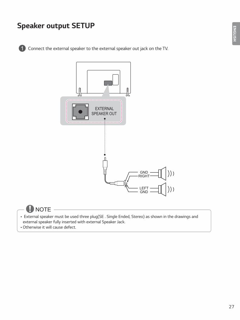
1 Connect the external speaker to the external speaker out jack on the TV.
GNDLEFT
EXTERNALSPEAKER OUT
RIGHTGND
NOTE• External speaker must be used three plug(SE : Single Ended, Stereo) as shown in the drawings and
external speaker fully inserted with external Speaker Jack.• Otherwise it will cause defect.

28
ENGLISH
HCEC Setup
CEC Mode
IR Decoding
Device ID
StandBy
HTNG HotelMode
HCEC Setup◄ Default ►
OKPrevious
No
All
All
No
Installation Menu (V 3.0)
Public Display ModeTV ManagerPassword ChangeSet ID SetupConfiguration SetupTime schedulerLock ModeExternal Speaker
Insert ImageHCEC Setup
OKS/W : 02.00.00.01 Micom : 0.00.84
1 Use the button to select the HCEC Setup.
(1) HCEC Setup• When ‘HCEC Setup’ is set to ‘HCEC Mode’, You can adjust ‘IR Decoding’, ‘Device ID’, ‘Stand By’ menu and
SIMPLINK feature automatically changed to the ON state, and the user can not change this status.
(a) IR Decoding• When ‘IR Decoding’ is set to ‘Yes’, the TV decodes and changes it into a CEC Message and sends it
to Command via the HDMI CEC Line. The default value is No.
(b) Device ID• Sets the ID of a device(Logical Address) connected to the CEC Line. You can choose between ‘All’
and ‘E’.• The default value is ‘All’.
29
ENGLISH
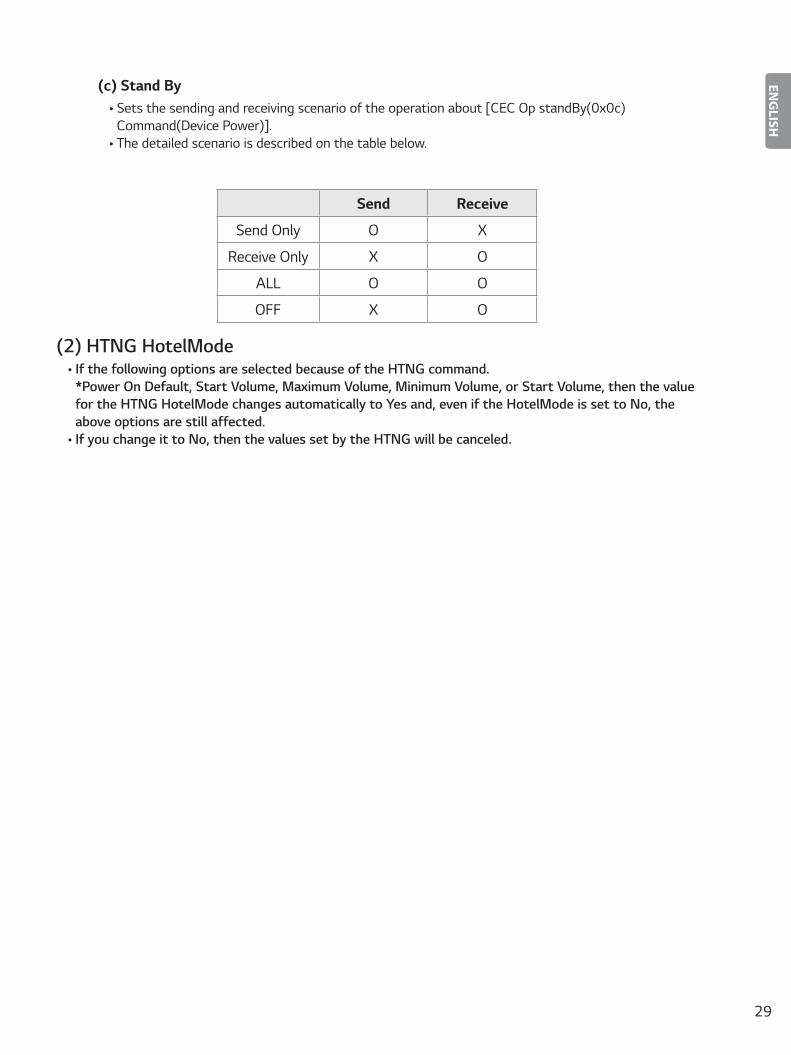
(c) Stand By• Sets the sending and receiving scenario of the operation about [CEC Op standBy(0x0c)
Command(Device Power)]. • The detailed scenario is described on the table below.
Send Receive
Send Only O X
Receive Only X O
ALL O O
OFF X O
(2) HTNG HotelMode• If the following options are selected because of the HTNG command:
*Power On Default, Start Volume, Maximum Volume, Minimum Volume, or Start Volume, then the value for the HTNG HotelMode changes automatically to Yes and, even if the HotelMode is set to No, the above options are still affected.
• If you change it to No, then the values set by the HTNG will be canceled.
30
ENGLISH
INSERT IMAGE
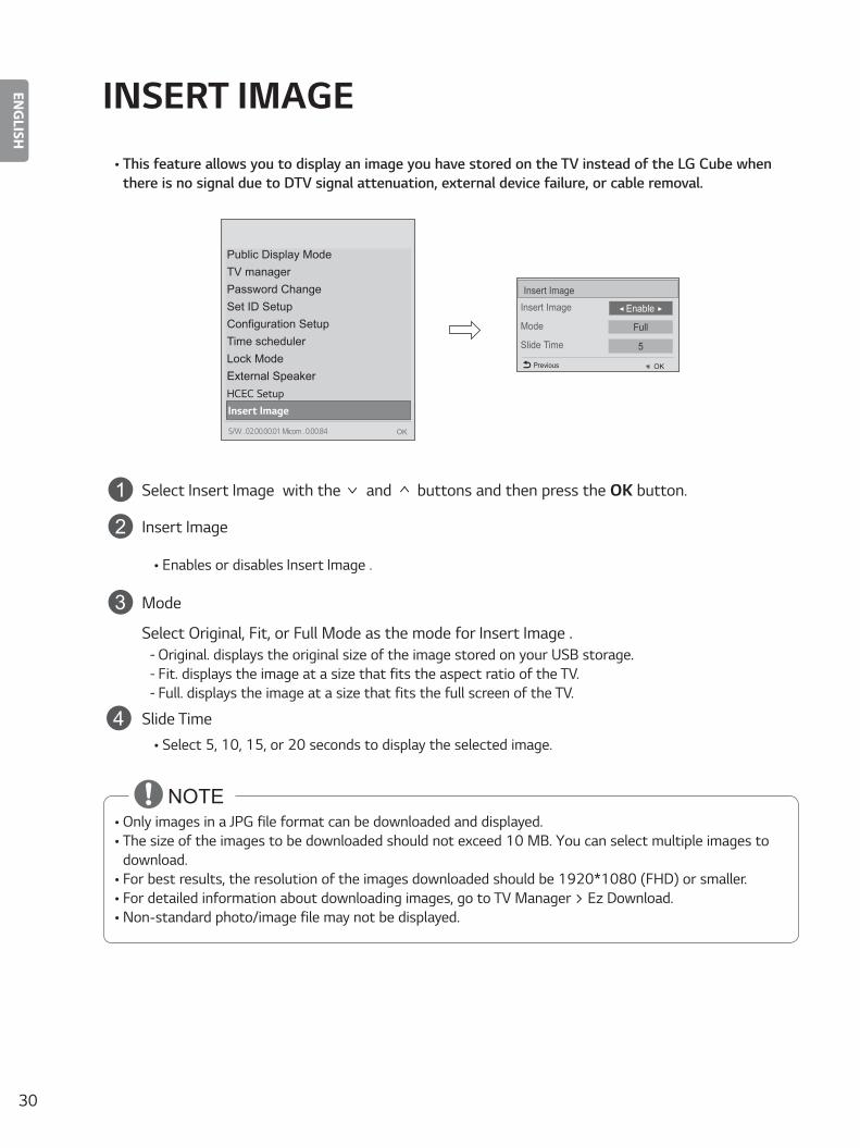
• This feature allows you to display an image you have stored on the TV instead of the LG Cube when there is no signal due to DTV signal attenuation, external device failure, or cable removal.
Public Display ModeTV managerPassword ChangeSet ID SetupConfiguration SetupTime schedulerLock ModeExternal SpeakerHCEC SetupInsert Image
OKS/W : 02.00.00.01 Micom : 0.00.84
Insert Image
Mode
Slide Time
Insert Image
◄ Enable ►
OKPrevious
Full
5
1 Select Insert Image with the and buttons and then press the OK button.
2 Insert Image
• Enables or disables Insert Image .
3 Mode
Select Original, Fit, or Full Mode as the mode for Insert Image . - Original: displays the original size of the image stored on your USB storage. - Fit: displays the image at a size that fits the aspect ratio of the TV. - Full: displays the image at a size that fits the full screen of the TV.
4 Slide Time• Select 5, 10, 15, or 20 seconds to display the selected image.
NOTE• Only images in a JPG file format can be downloaded and displayed.• The size of the images to be downloaded should not exceed 10 MB. You can select multiple images to
download.• For best results, the resolution of the images downloaded should be 1920*1080 (FHD) or smaller.• For detailed information about downloading images, go to TV Manager > Ez Download.• Non-standard photo/image file may not be displayed.
31
ENGLISH
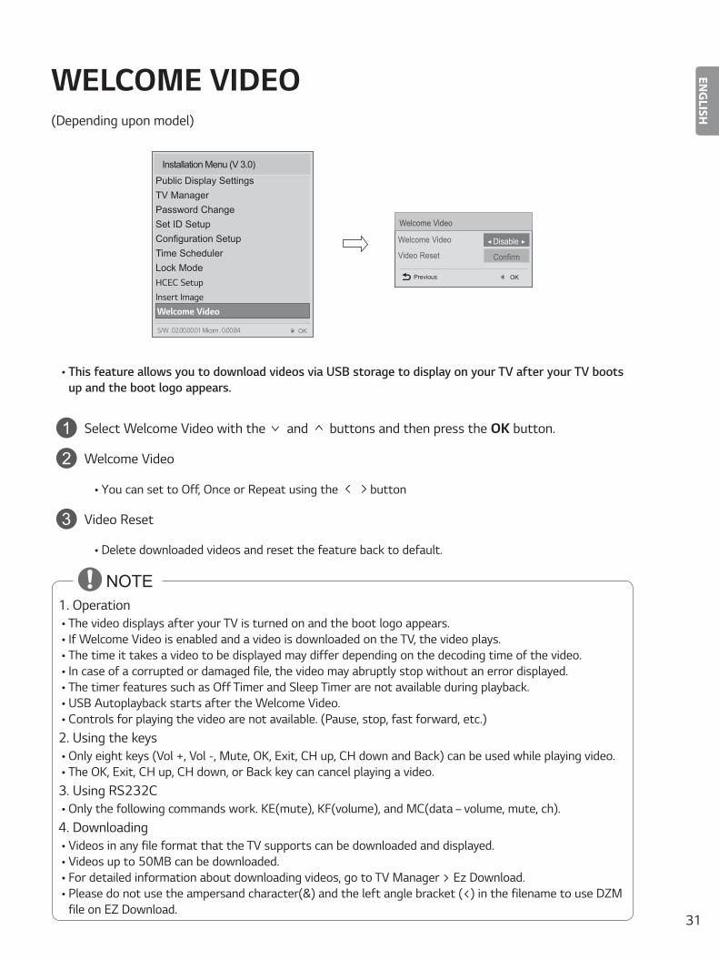
WELCOME VIDEO(Depending upon model)
Welcome Video
Video Reset
Welcome Video
Confirm
◄ Disable ►
Previous OK
Installation Menu (V 3.0)
Public Display SettingsTV ManagerPassword ChangeSet ID SetupConfiguration SetupTime SchedulerLock ModeHCEC SetupInsert ImageWelcome Video
OKS/W : 02.00.00.01 Micom : 0.00.84
• This feature allows you to download videos via USB storage to display on your TV after your TV boots up and the boot logo appears.
1 Select Welcome Video with the and buttons and then press the OK button.
2 Welcome Video
• You can set to Off, Once or Repeat using the button
3 Video Reset
• Delete downloaded videos and reset the feature back to default.
NOTE 1. Operation
• The video displays after your TV is turned on and the boot logo appears.• If Welcome Video is enabled and a video is downloaded on the TV, the video plays.• The time it takes a video to be displayed may differ depending on the decoding time of the video.• In case of a corrupted or damaged file, the video may abruptly stop without an error displayed.• The timer features such as Off Timer and Sleep Timer are not available during playback.• USB Autoplayback starts after the Welcome Video.• Controls for playing the video are not available. (Pause, stop, fast forward, etc.)
2. Using the keys• Only eight keys (Vol +, Vol -, Mute, OK, Exit, CH up, CH down and Back) can be used while playing video.• The OK, Exit, CH up, CH down, or Back key can cancel playing a video.
3. Using RS232C• Only the following commands work: KE(mute), KF(volume), and MC(data – volume, mute, ch).
4. Downloading• Videos in any file format that the TV supports can be downloaded and displayed.• Videos up to 50MB can be downloaded.• For detailed information about downloading videos, go to TV Manager > Ez Download.• Please do not use the ampersand character(&) and the left angle bracket (<) in the filename to use DZM
file on EZ Download.
32
ENGLISH
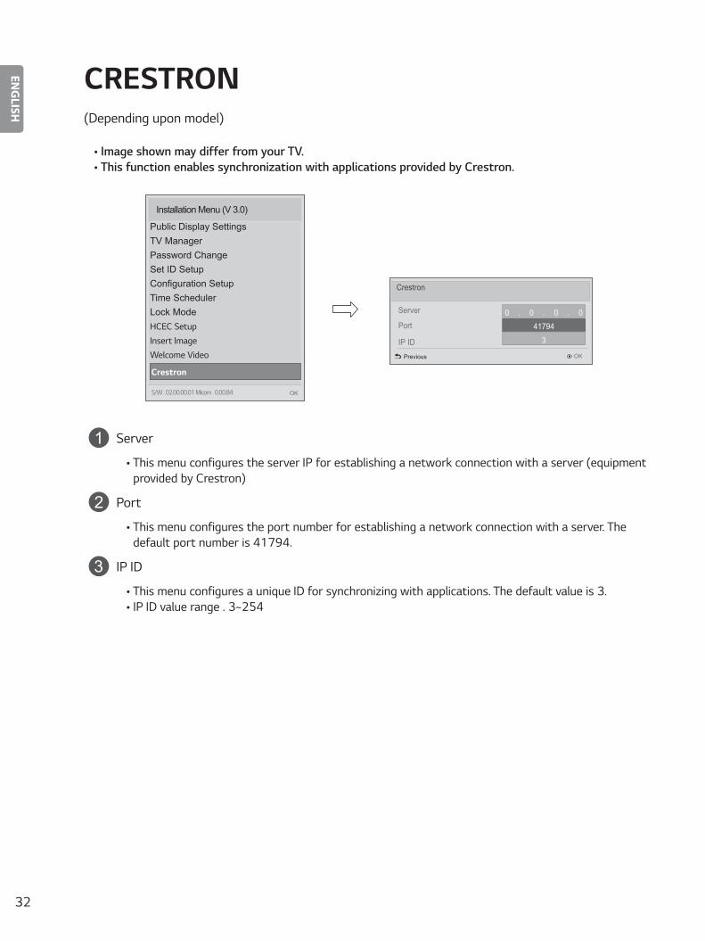
CRESTRON(Depending upon model)
• Image shown may differ from your TV.• This function enables synchronization with applications provided by Crestron.
Installation Menu (V 3.0)
Public Display SettingsTV ManagerPassword ChangeSet ID SetupConfiguration SetupTime SchedulerLock ModeHCEC SetupInsert ImageWelcome Video
Crestron
OKS/W : 02.00.00.01 Micom : 0.00.84
Server
Port
Crestron
0 . 0 . 0 . 041794
3
OKPrevious
IP ID
1 Server
• This menu configures the server IP for establishing a network connection with a server (equipment provided by Crestron)
2 Port
• This menu configures the port number for establishing a network connection with a server. The default port number is 41794.
3 IP ID
• This menu configures a unique ID for synchronizing with applications. The default value is 3.• IP ID value range : 3~254

33
ENGLISH
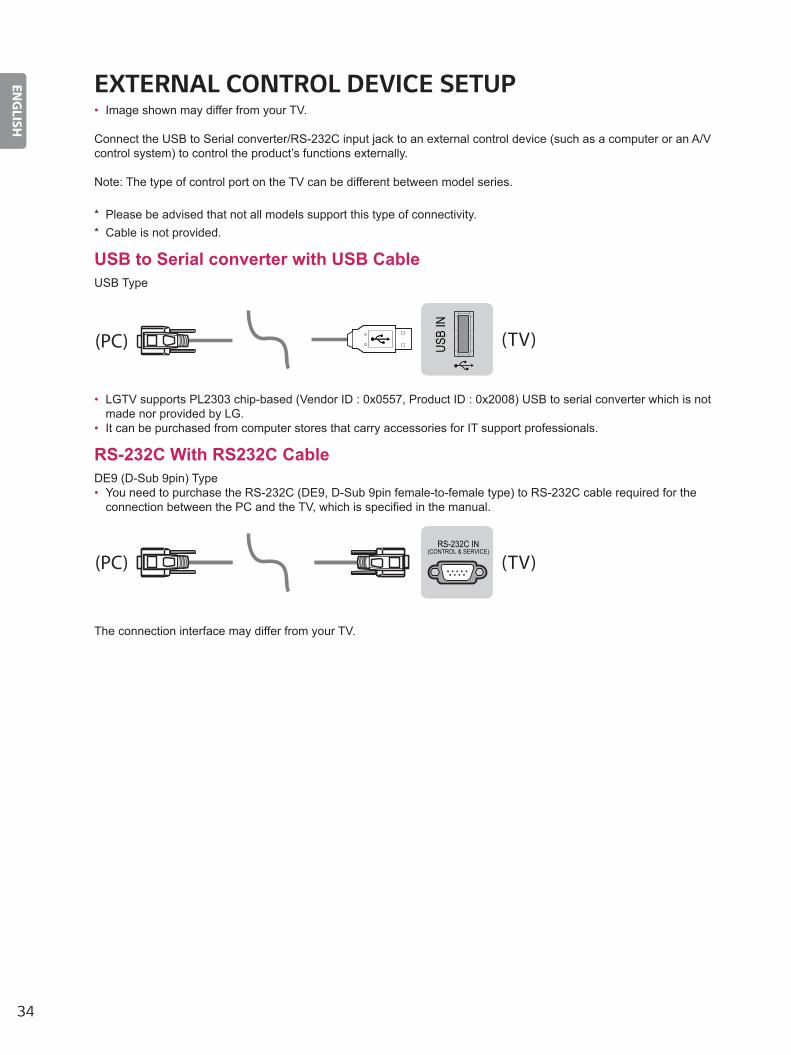
EXTERNAL CONTROL DEVICE SETUP
KEY CODES• This feature is not available for all models.
Code (Hexa) Function Note Code
(Hexa) Function Note
00 CH +, PR + R/C Button 4C List, - (ATSC Only) R/C Button01 CH -, PR - R/C Button 53 List R/C Button02 Volume + R/C Button 5B Exit R/C Button03 Volume - R/C Button 60 PIP(AD) R/C Button06 (Arrow Key / Right Key) R/C Button 61 R/C Button07 (Arrow Key / Left Key) R/C Button 63 R/C Button08 Power R/C Button 71 R/C Button09 Mute R/C Button 72 R/C Button0B Input R/C Button 79 Ratio / Aspect Ratio R/C Button0E SLEEP R/C Button 91 AD (Audio Description) R/C Button0F TV, TV/RAD R/C Button 7A User Guide R/C Button
10 - 19 * Number Key 0 - 9 R/C Button 7C Smart / Home R/C Button1A Q.View / Flashback R/C Button 7E SIMPLINK R/C Button1E FAV (Favorite Channel) R/C Button 8E (Forward) R/C Button20 Text (Teletext) R/C Button 8F (Rewind) R/C Button21 T. Opt (Teletext Option) R/C Button AA Info R/C Button28 Return (BACK) R/C Button AB Program Guide R/C Button30 AV (Audio / Video) Mode R/C Button B0 (Play) R/C Button39 Caption/Subtitle R/C Button B1 (Stop / File List) R/C Button
40 (Arrow Key / Cursor Up) R/C Button BA (Freeze / Slow Play / Pause) R/C Button
41 (Arrow Key / Cursor Down) R/C Button BB Soccer R/C Button42 My Apps R/C Button BD (REC) R/C Button43 Menu / Settings R/C Button DC 3D R/C Button44 OK / Enter R/C Button 9F App / * R/C Button
45 Q.Menu R/C Button 9B TV/PC R/C Button• Key code 4C (0x4C) is available on ATSC/ISDB models which use major/minor channel. (For South
Korea, Japan, North America, Latin America except Colombia models)
34
ENGLISH
EXTERNAL CONTROL DEVICE SETUP• Image shown may differ from your TV.
Connect the USB to Serial converter/RS-232C input jack to an external control device (such as a computer or an A/V control system) to control the product’s functions externally.
Note: The type of control port on the TV can be different between model series.
* Please be advised that not all models support this type of connectivity.* Cable is not provided.
USB to Serial converter with USB CableUSB Type
USB
IN
(TV)
(PC)
(PC)
RS-232C IN(CONTROL & SERVICE)
(TV)
(TV)(PC)
(TV)(PC)
SERV
ICE
ONLY
RS-232C IN(CONTROL & SERVICE)
RS-232C IN(CONTROL & SERVICE)
13
2
13
2
• LGTV supports PL2303 chip-based (Vendor ID : 0x0557, Product ID : 0x2008) USB to serial converter which is not made nor provided by LG.
• It can be purchased from computer stores that carry accessories for IT support professionals.
RS-232C With RS232C CableDE9 (D-Sub 9pin) Type• You need to purchase the RS-232C (DE9, D-Sub 9pin female-to-female type) to RS-232C cable required for the
connection between the PC and the TV, which is specified in the manual.
USB
IN
(TV)
(PC)
(PC)
RS-232C IN(CONTROL & SERVICE)
(TV)
(TV)(PC)
(TV)(PC)
SERV
ICE
ONLY
RS-232C IN(CONTROL & SERVICE)
RS-232C IN(CONTROL & SERVICE)
13
2
13
2
The connection interface may differ from your TV.
35
ENGLISH
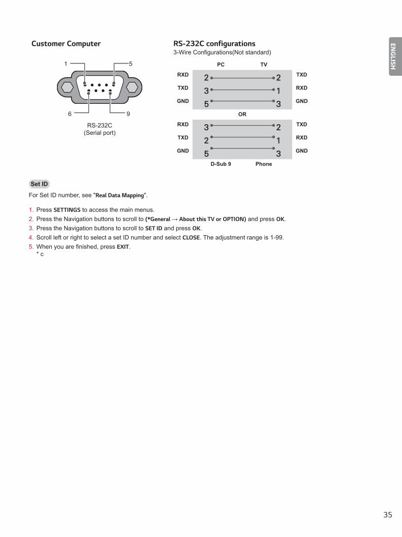
Customer Computer RS-232C configurations3-Wire Configurations(Not standard)
1
6
5
9
PC TV
RXD 2 2 TXD
TXD 3 1 RXD
GND 5 3 GND
OR
RXD 3 2 TXD
TXD 2 1 RXD
GND 5 3 GND
D-Sub 9 Phone
RS-232C(Serial port)
Set ID
For Set ID number, see "Real Data Mapping".
1. Press SETTINGS to access the main menus.2. Press the Navigation buttons to scroll to (*General → About this TV or OPTION) and press OK.3. Press the Navigation buttons to scroll to SET ID and press OK.4. Scroll left or right to select a set ID number and select CLOSE. The adjustment range is 1-99.5. When you are finished, press EXIT.
* c
36
ENGLISH
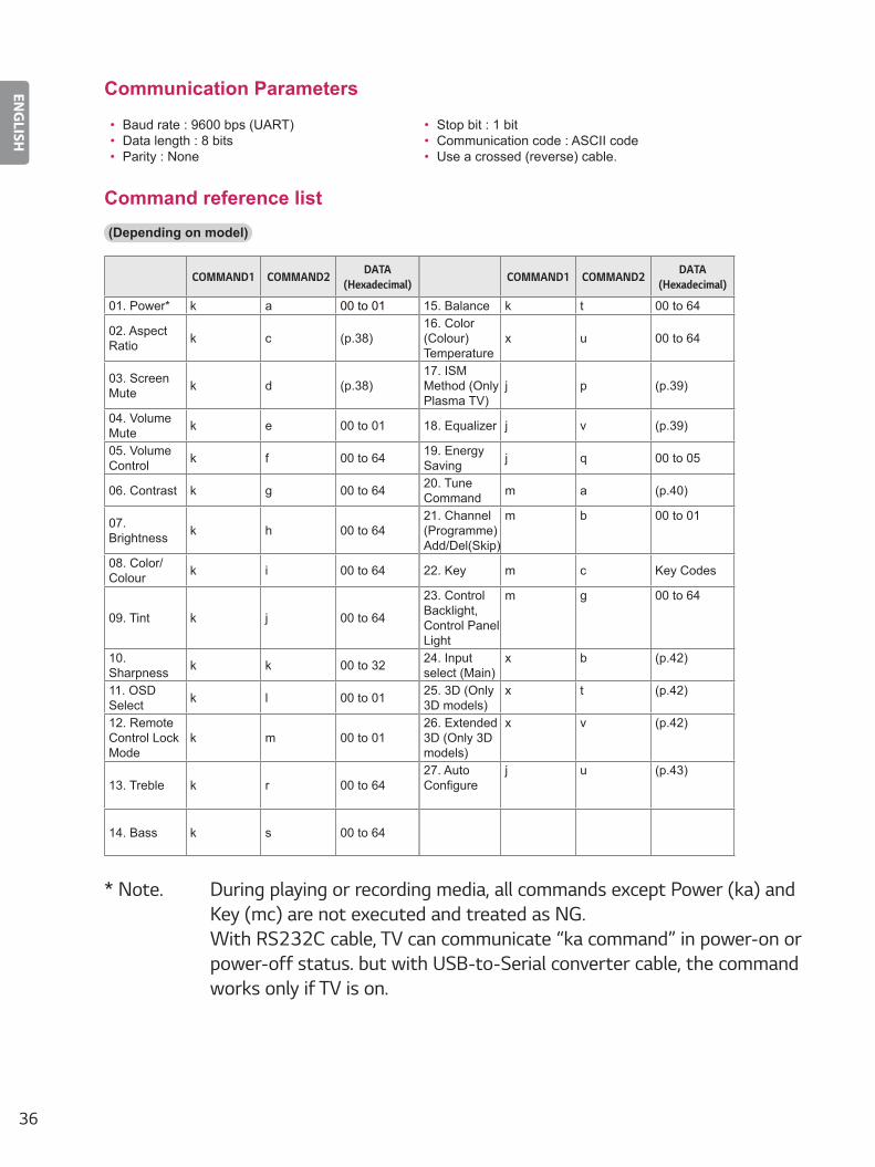
Communication Parameters
• Baud rate : 9600 bps (UART)• Data length : 8 bits• Parity : None
• Stop bit : 1 bit• Communication code : ASCII code• Use a crossed (reverse) cable.
Command reference list(Depending on model)
COMMAND1 COMMAND2 DATA(Hexadecimal) COMMAND1 COMMAND2 DATA
(Hexadecimal)
01. Power* k a 00 to 01 15. Balance k t 00 to 64
02. Aspect Ratio k c (p.38)
16. Color (Colour)Temperature
x u 00 to 64
03. Screen Mute k d (p.38)
17. ISM Method (Only Plasma TV)
j p (p.39)
04. Volume Mute k e 00 to 01 18. Equalizer j v (p.39)
05. Volume Control k f 00 to 64 19. Energy
Saving j q 00 to 05
06. Contrast k g 00 to 64 20. Tune Command m a (p.40)
07. Brightness k h 00 to 64
21. Channel(Programme)Add/Del(Skip)
m b 00 to 01
08. Color/Colour k i 00 to 64 22. Key m c Key Codes
09. Tint k j 00 to 64
23. Control Backlight, Control Panel Light
m g 00 to 64
10. Sharpness k k 00 to 32 24. Input
select (Main)x b (p.42)
11. OSD Select k l 00 to 01 25. 3D (Only
3D models)x t (p.42)
12. Remote Control Lock Mode
k m 00 to 0126. Extended 3D (Only 3D models)
x v (p.42)
13. Treble k r 00 to 6427. Auto Configure
j u (p.43)
14. Bass k s 00 to 64
* Note: During playing or recording media, all commands except Power (ka) and Key (mc) are not executed and treated as NG. With RS232C cable, TV can communicate “ka command” in power-on or power-off status. but with USB-to-Serial converter cable, the command works only if TV is on.

37
ENGLISH
Transmission / Receiving ProtocolTransmission
[Command1][Command2][ ][Set ID][ ][Data][Cr]
[Command 1] : First command to control the TV. (j, k, m or x)[Command 2] : Second command to control the TV.[Set ID] : You can adjust the [Set ID] to choose desired monitor ID number in option menu.
Adjustment range in TV is 1 to 99. If [Set ID] value is selected to ‘0’, every connected set can be controlled.
* [Set ID] is indicated as decimal (1 to 99) on menu and as Hexadecimal (0x00 to 0x63) on transmission/receiving protocol.
[DATA] : To transmit command data (hexadecimal). Transmit ‘FF’ data to read status of command.[Cr] : Carriage Return - ASCII code ‘0x0D’[ ] : Space – ASCII code ‘0x20’
OK Acknowledgement
[Command2][ ][Set ID][ ][OK][Data][x]
* The set transmits ACK (acknowledgement) based on this format when receiving normal data. At this time, if the data is data read mode, it indicates present status data. If the data is data write mode, it returns the data of the PC computer.
Error Acknowledgement
[Command2][ ][Set ID][ ][NG][Data][x]
* The set transmits ACK (acknowledgement) based on this format when receiving abnormal data from non-viable functions or communication errors.
Data 00: Illegal Code
Real data mapping (Hexadecimal : Decimal)
* When you enter the [data] in hexadecimal, refer to following conversion table.* Channel Tune (ma) Command uses two-byte hexadecimal value([data]) to select channel number.
00 : Step 0 32 : Step 50 (Set ID 50) FE : Step 25401 : Step 1 (Set ID 1) 33 : Step 51 (Set ID 51) FF : Step 255... ... ...0A : Step 10 (Set ID 10) 63 : Step 99 (Set ID 99) 01 00 : Step 256... ... ...0F : Step 15 (Set ID 15) C7 : Step 199 27 0E : Step 999810 : Step 16 (Set ID 16) C8 : Step 200 27 0F : Step 9999... ... ...
38
ENGLISH
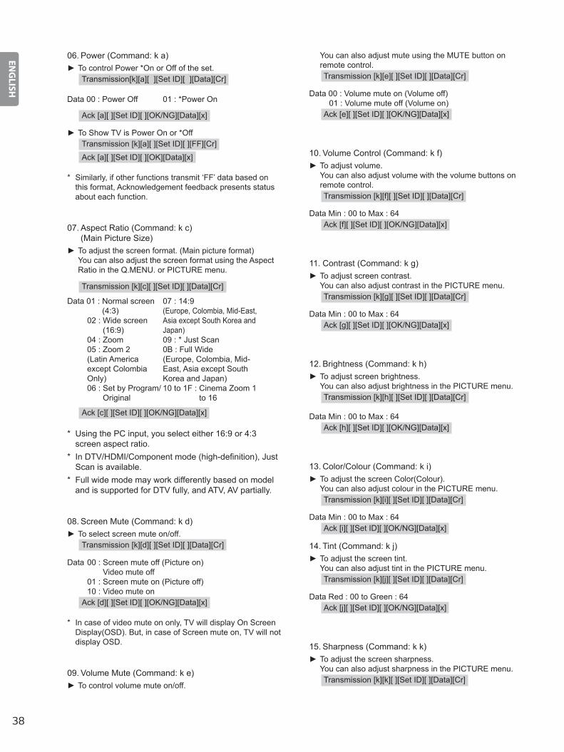
06. Power (Command: k a) ► To control Power *On or Off of the set.
Transmission[k][a][ ][Set ID][ ][Data][Cr]
Data 00 : Power Off 01 : *Power On
Ack [a][ ][Set ID][ ][OK/NG][Data][x]
► To Show TV is Power On or *OffTransmission [k][a][ ][Set ID][ ][FF][Cr]
Ack [a][ ][Set ID][ ][OK][Data][x]
* Similarly, if other functions transmit ‘FF’ data based on this format, Acknowledgement feedback presents status about each function.
07. Aspect Ratio (Command: k c) (Main Picture Size)
► To adjust the screen format. (Main picture format) You can also adjust the screen format using the Aspect Ratio in the Q.MENU. or PICTURE menu.
Transmission [k][c][ ][Set ID][ ][Data][Cr]
Data 01 : Normal screen (4:3)
02 : Wide screen (16:9)
04 : Zoom 05 : Zoom 2 (Latin America
except Colombia Only)
06 : Set by Program/ Original
07 : 14:9(Europe, Colombia, Mid-East, Asia except South Korea and Japan)09 : * Just Scan0B : Full Wide(Europe, Colombia, Mid-East, Asia except South Korea and Japan)10 to 1F : Cinema Zoom 1
to 16
Ack [c][ ][Set ID][ ][OK/NG][Data][x]
* Using the PC input, you select either 16:9 or 4:3 screen aspect ratio.
* In DTV/HDMI/Component mode (high-definition), Just Scan is available.
* Full wide mode may work differently based on model and is supported for DTV fully, and ATV, AV partially.
08. Screen Mute (Command: k d) ► To select screen mute on/off.
Transmission [k][d][ ][Set ID][ ][Data][Cr]
Data 00 : Screen mute off (Picture on) Video mute off
01 : Screen mute on (Picture off) 10 : Video mute on
Ack [d][ ][Set ID][ ][OK/NG][Data][x]
* In case of video mute on only, TV will display On Screen Display(OSD). But, in case of Screen mute on, TV will not display OSD.
09. Volume Mute (Command: k e) ► To control volume mute on/off.
You can also adjust mute using the MUTE button on remote control.Transmission [k][e][ ][Set ID][ ][Data][Cr]
Data 00 : Volume mute on (Volume off) 01 : Volume mute off (Volume on)
Ack [e][ ][Set ID][ ][OK/NG][Data][x]
10. Volume Control (Command: k f) ► To adjust volume. You can also adjust volume with the volume buttons on remote control.Transmission [k][f][ ][Set ID][ ][Data][Cr]
Data Min : 00 to Max : 64Ack [f][ ][Set ID][ ][OK/NG][Data][x]
11. Contrast (Command: k g) ► To adjust screen contrast. You can also adjust contrast in the PICTURE menu.Transmission [k][g][ ][Set ID][ ][Data][Cr]
Data Min : 00 to Max : 64Ack [g][ ][Set ID][ ][OK/NG][Data][x]
12. Brightness (Command: k h) ► To adjust screen brightness. You can also adjust brightness in the PICTURE menu.Transmission [k][h][ ][Set ID][ ][Data][Cr]
Data Min : 00 to Max : 64Ack [h][ ][Set ID][ ][OK/NG][Data][x]
13. Color/Colour (Command: k i) ► To adjust the screen Color(Colour). You can also adjust colour in the PICTURE menu.Transmission [k][i][ ][Set ID][ ][Data][Cr]
Data Min : 00 to Max : 64Ack [i][ ][Set ID][ ][OK/NG][Data][x]
14. Tint (Command: k j) ► To adjust the screen tint. You can also adjust tint in the PICTURE menu.Transmission [k][j][ ][Set ID][ ][Data][Cr]
Data Red : 00 to Green : 64Ack [j][ ][Set ID][ ][OK/NG][Data][x]
15. Sharpness (Command: k k) ► To adjust the screen sharpness. You can also adjust sharpness in the PICTURE menu.Transmission [k][k][ ][Set ID][ ][Data][Cr]
39
ENGLISH
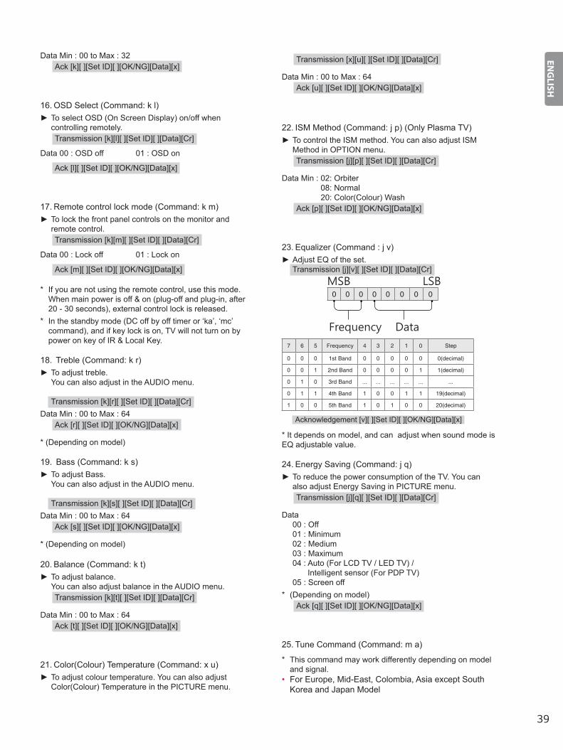
Data Min : 00 to Max : 32Ack [k][ ][Set ID][ ][OK/NG][Data][x]
16. OSD Select (Command: k l) ► To select OSD (On Screen Display) on/off when controlling remotely.Transmission [k][l][ ][Set ID][ ][Data][Cr]
Data 00 : OSD off 01 : OSD on
Ack [l][ ][Set ID][ ][OK/NG][Data][x]
17. Remote control lock mode (Command: k m) ► To lock the front panel controls on the monitor and remote control.Transmission [k][m][ ][Set ID][ ][Data][Cr]
Data 00 : Lock off 01 : Lock on
Ack [m][ ][Set ID][ ][OK/NG][Data][x]
* If you are not using the remote control, use this mode. When main power is off & on (plug-off and plug-in, after 20 - 30 seconds), external control lock is released.
* In the standby mode (DC off by off timer or ‘ka’, ‘mc’ command), and if key lock is on, TV will not turn on by power on key of IR & Local Key.
18. Treble (Command: k r) ► To adjust treble. You can also adjust in the AUDIO menu.
Transmission [k][r][ ][Set ID][ ][Data][Cr]Data Min : 00 to Max : 64
Ack [r][ ][Set ID][ ][OK/NG][Data][x]
* (Depending on model)
19. Bass (Command: k s) ► To adjust Bass. You can also adjust in the AUDIO menu.
Transmission [k][s][ ][Set ID][ ][Data][Cr]Data Min : 00 to Max : 64
Ack [s][ ][Set ID][ ][OK/NG][Data][x]
* (Depending on model)
20. Balance (Command: k t) ► To adjust balance. You can also adjust balance in the AUDIO menu.Transmission [k][t][ ][Set ID][ ][Data][Cr]
Data Min : 00 to Max : 64Ack [t][ ][Set ID][ ][OK/NG][Data][x]
21. Color(Colour) Temperature (Command: x u) ► To adjust colour temperature. You can also adjust Color(Colour) Temperature in the PICTURE menu.
Transmission [x][u][ ][Set ID][ ][Data][Cr]
Data Min : 00 to Max : 64Ack [u][ ][Set ID][ ][OK/NG][Data][x]
22. ISM Method (Command: j p) (Only Plasma TV) ► To control the ISM method. You can also adjust ISM Method in OPTION menu.Transmission [j][p][ ][Set ID][ ][Data][Cr]
Data Min : 02: Orbiter 08: Normal 20: Color(Colour) Wash
Ack [p][ ][Set ID][ ][OK/NG][Data][x]
23. Equalizer (Command : j v) ► Adjust EQ of the set.Transmission [j][v][ ][Set ID][ ][Data][Cr]
0 0 0 0 0 0 0 0
MSB
Frequency Data
LSB
7 6 5 Frequency 4 3 2 1 0 Step
0 0 0 1st Band 0 0 0 0 0 0(decimal)
0 0 1 2nd Band 0 0 0 0 1 1(decimal)
0 1 0 3rd Band ... ... ... ... ... ...
0 1 1 4th Band 1 0 0 1 1 19(decimal)
1 0 0 5th Band 1 0 1 0 0 20(decimal)
Acknowledgement [v][ ][Set ID][ ][OK/NG][Data][x]
* It depends on model, and can adjust when sound mode is EQ adjustable value.
24. Energy Saving (Command: j q) ► To reduce the power consumption of the TV. You can also adjust Energy Saving in PICTURE menu.Transmission [j][q][ ][Set ID][ ][Data][Cr]
Data 00 : Off 01 : Minimum 02 : Medium 03 : Maximum 04 : Auto (For LCD TV / LED TV) /
Intelligent sensor (For PDP TV) 05 : Screen off* (Depending on model)
Ack [q][ ][Set ID][ ][OK/NG][Data][x]
25. Tune Command (Command: m a)
* This command may work differently depending on model and signal.
• For Europe, Mid-East, Colombia, Asia except South Korea and Japan Model
40
ENGLISH
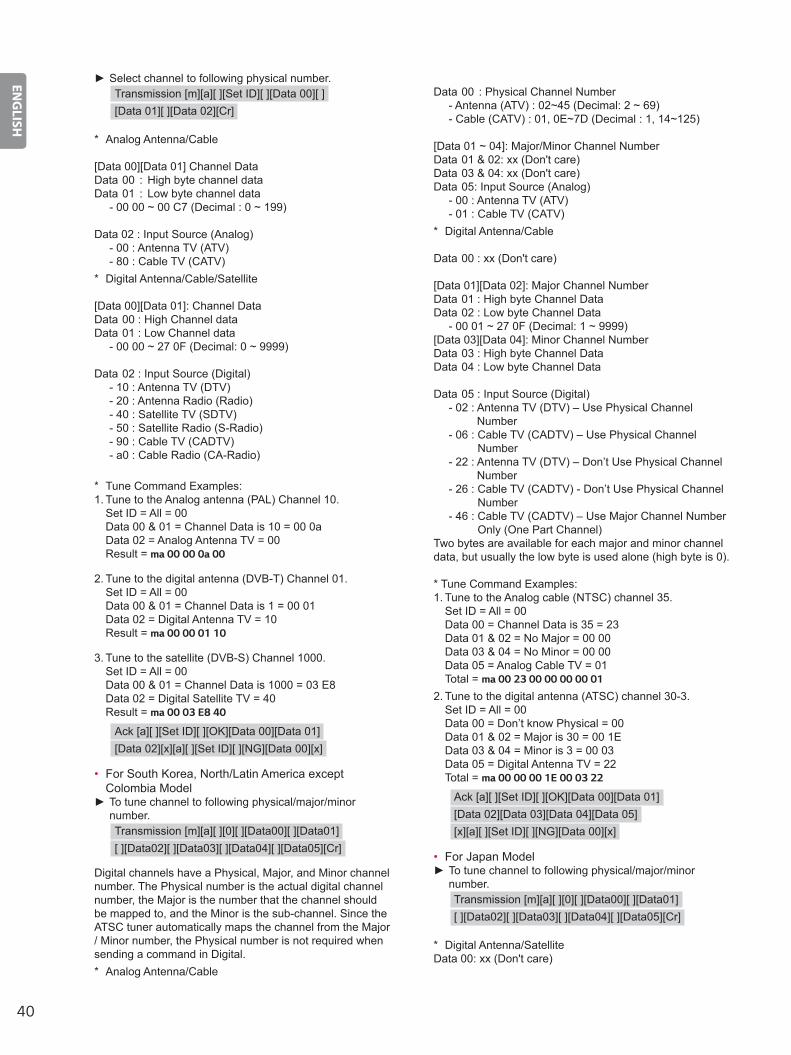
► Select channel to following physical number.Transmission [m][a][ ][Set ID][ ][Data 00][ ][Data 01][ ][Data 02][Cr]
* Analog Antenna/Cable
[Data 00][Data 01] Channel DataData 00 : High byte channel dataData 01 : Low byte channel data - 00 00 ~ 00 C7 (Decimal : 0 ~ 199)
Data 02 : Input Source (Analog) - 00 : Antenna TV (ATV) - 80 : Cable TV (CATV)* Digital Antenna/Cable/Satellite
[Data 00][Data 01]: Channel DataData 00 : High Channel dataData 01 : Low Channel data - 00 00 ~ 27 0F (Decimal: 0 ~ 9999)
Data 02 : Input Source (Digital) - 10 : Antenna TV (DTV) - 20 : Antenna Radio (Radio) - 40 : Satellite TV (SDTV) - 50 : Satellite Radio (S-Radio) - 90 : Cable TV (CADTV) - a0 : Cable Radio (CA-Radio)
* Tune Command Examples:1. Tune to the Analog antenna (PAL) Channel 10.
Set ID = All = 00 Data 00 & 01 = Channel Data is 10 = 00 0a Data 02 = Analog Antenna TV = 00 Result = ma 00 00 0a 00
2. Tune to the digital antenna (DVB-T) Channel 01. Set ID = All = 00 Data 00 & 01 = Channel Data is 1 = 00 01 Data 02 = Digital Antenna TV = 10 Result = ma 00 00 01 10
3. Tune to the satellite (DVB-S) Channel 1000. Set ID = All = 00 Data 00 & 01 = Channel Data is 1000 = 03 E8 Data 02 = Digital Satellite TV = 40 Result = ma 00 03 E8 40
Ack [a][ ][Set ID][ ][OK][Data 00][Data 01][Data 02][x][a][ ][Set ID][ ][NG][Data 00][x]
• For South Korea, North/Latin America except Colombia Model ► To tune channel to following physical/major/minor number.Transmission [m][a][ ][0][ ][Data00][ ][Data01][ ][Data02][ ][Data03][ ][Data04][ ][Data05][Cr]
Digital channels have a Physical, Major, and Minor channel number. The Physical number is the actual digital channel number, the Major is the number that the channel should be mapped to, and the Minor is the sub-channel. Since the ATSC tuner automatically maps the channel from the Major / Minor number, the Physical number is not required when sending a command in Digital.* Analog Antenna/Cable
Data 00 : Physical Channel Number - Antenna (ATV) : 02~45 (Decimal: 2 ~ 69) - Cable (CATV) : 01, 0E~7D (Decimal : 1, 14~125)
[Data 01 ~ 04]: Major/Minor Channel NumberData 01 & 02: xx (Don't care)Data 03 & 04: xx (Don't care)Data 05: Input Source (Analog) - 00 : Antenna TV (ATV) - 01 : Cable TV (CATV)* Digital Antenna/Cable
Data 00 : xx (Don't care)
[Data 01][Data 02]: Major Channel NumberData 01 : High byte Channel DataData 02 : Low byte Channel Data - 00 01 ~ 27 0F (Decimal: 1 ~ 9999)[Data 03][Data 04]: Minor Channel NumberData 03 : High byte Channel DataData 04 : Low byte Channel Data
Data 05 : Input Source (Digital) - 02 : Antenna TV (DTV) – Use Physical Channel
Number - 06 : Cable TV (CADTV) – Use Physical Channel
Number - 22 : Antenna TV (DTV) – Don’t Use Physical Channel
Number - 26 : Cable TV (CADTV) - Don’t Use Physical Channel
Number - 46 : Cable TV (CADTV) – Use Major Channel Number
Only (One Part Channel)Two bytes are available for each major and minor channel data, but usually the low byte is used alone (high byte is 0).
* Tune Command Examples:1. Tune to the Analog cable (NTSC) channel 35.
Set ID = All = 00 Data 00 = Channel Data is 35 = 23 Data 01 & 02 = No Major = 00 00 Data 03 & 04 = No Minor = 00 00 Data 05 = Analog Cable TV = 01 Total = ma 00 23 00 00 00 00 01
2. Tune to the digital antenna (ATSC) channel 30-3. Set ID = All = 00 Data 00 = Don’t know Physical = 00 Data 01 & 02 = Major is 30 = 00 1E Data 03 & 04 = Minor is 3 = 00 03 Data 05 = Digital Antenna TV = 22 Total = ma 00 00 00 1E 00 03 22
Ack [a][ ][Set ID][ ][OK][Data 00][Data 01][Data 02][Data 03][Data 04][Data 05][x][a][ ][Set ID][ ][NG][Data 00][x]
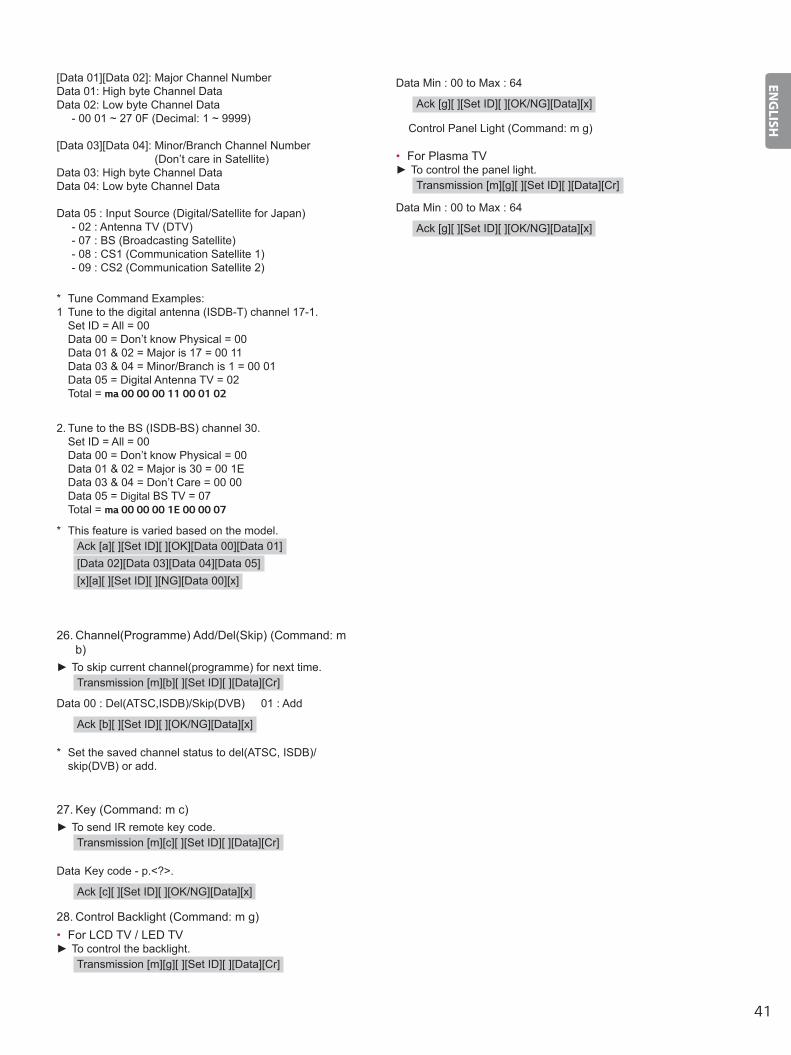
• For Japan Model ► To tune channel to following physical/major/minor number.Transmission [m][a][ ][0][ ][Data00][ ][Data01][ ][Data02][ ][Data03][ ][Data04][ ][Data05][Cr]
* Digital Antenna/SatelliteData 00: xx (Don't care)
41
ENGLISH
[Data 01][Data 02]: Major Channel NumberData 01: High byte Channel DataData 02: Low byte Channel Data - 00 01 ~ 27 0F (Decimal: 1 ~ 9999)
[Data 03][Data 04]: Minor/Branch Channel Number (Don’t care in Satellite)
Data 03: High byte Channel DataData 04: Low byte Channel Data
Data 05 : Input Source (Digital/Satellite for Japan) - 02 : Antenna TV (DTV) - 07 : BS (Broadcasting Satellite) - 08 : CS1 (Communication Satellite 1) - 09 : CS2 (Communication Satellite 2)
* Tune Command Examples:1 Tune to the digital antenna (ISDB-T) channel 17-1.
Set ID = All = 00 Data 00 = Don’t know Physical = 00 Data 01 & 02 = Major is 17 = 00 11 Data 03 & 04 = Minor/Branch is 1 = 00 01 Data 05 = Digital Antenna TV = 02 Total = ma 00 00 00 11 00 01 02
2. Tune to the BS (ISDB-BS) channel 30. Set ID = All = 00 Data 00 = Don’t know Physical = 00 Data 01 & 02 = Major is 30 = 00 1E Data 03 & 04 = Don’t Care = 00 00 Data 05 = Digital BS TV = 07 Total = ma 00 00 00 1E 00 00 07
* This feature is varied based on the model.Ack [a][ ][Set ID][ ][OK][Data 00][Data 01][Data 02][Data 03][Data 04][Data 05][x][a][ ][Set ID][ ][NG][Data 00][x]
26. Channel(Programme) Add/Del(Skip) (Command: m b)
► To skip current channel(programme) for next time.Transmission [m][b][ ][Set ID][ ][Data][Cr]
Data 00 : Del(ATSC,ISDB)/Skip(DVB) 01 : Add
Ack [b][ ][Set ID][ ][OK/NG][Data][x]
* Set the saved channel status to del(ATSC, ISDB)/ skip(DVB) or add.
27. Key (Command: m c) ► To send IR remote key code.
Transmission [m][c][ ][Set ID][ ][Data][Cr]
Data Key code - p.<?>.
Ack [c][ ][Set ID][ ][OK/NG][Data][x]
28. Control Backlight (Command: m g)• For LCD TV / LED TV
► To control the backlight.Transmission [m][g][ ][Set ID][ ][Data][Cr]
Data Min : 00 to Max : 64
Ack [g][ ][Set ID][ ][OK/NG][Data][x]
Control Panel Light (Command: m g)
• For Plasma TV ► To control the panel light.
Transmission [m][g][ ][Set ID][ ][Data][Cr]
Data Min : 00 to Max : 64
Ack [g][ ][Set ID][ ][OK/NG][Data][x]

42
ENGLISH
29. Input select (Command: x b) (Main Picture Input)
► To select input source for main picture.Transmission [x][b][ ][Set ID][ ][Data][Cr]
Data 00 : DTV 02 : Satellite DTV
ISDB-BS (Japan) 03 : ISDB-CS1 (Japan) 04 : ISDB-CS2 (Japan) 11 : CATV
01 : CADTV10 : ATV
20 : AV or AV1 21 : AV2
40 : Component1 60 : RGB
41 : Component2
90 : HDMI1 92 : HDMI3
91 : HDMI293 : HDMI4
Ack [b][ ][Set ID][ ][OK/NG][Data][x]
* This function depends on model and signal.
30. 3D(Command: x t) (only 3D models) (Depending on model)
► To change 3D mode for TV.Transmission [x][t][ ][Set ID][ ][Data 00][ ][Data 01][ ][Data 02][ ][Data 03][Cr]
* (Depending on model)Data Structure[Data 00] 00 : 3D On
01 : 3D Off 02 : 3D to 2D 03 : 2D to 3D
[Data 01] 00 : Top and Bottom 01 : Side by Side 02 : Check Board 03 : Frame Sequential 04 : Column interleaving 05 : Row interleaving
[Data 02] 00 : Right to Left 01 : Left to Right
[Data 03] 3D Effect(3D Depth): Min : 00 - Max : 14 (*transmit by Hexadecimal code)
* [Data 02], [Data 03] functions depend on model and signal.
* If [Data 00] is 00 (3D On), [Data 03] has no meaning.* If [Data 00] is 01 (3D off) or 02 (3D to 2D), [Data 01],
[Data 02] and [Data 03] have no meaning.* If [Data 00] is 03 (2D to 3D), [Data 01] and
[Data 02] have no meaning.* If [Data 00] is 00 (3D On) or 03 (2D to 3D), [Data
03] works when 3D Mode (Genre) is manual only.* All 3D pattern options ([Data 01]) may not be available
according to broadcasting/video signal.
[Data 00] [Data 01] [Data 02] [Data 03]
00 O O O
01 X X X
02 X X X
03 X O O
X : don’t care
Ack [t][ ][Set ID][ ][OK][Data00][Data01][Data02][Data03][x][t][ ][Set ID][ ][NG][Data00][x]
31. Extended 3D(Command: x v) (only 3D models) (Depending on model)
► To change 3D option for TV.Transmission [x][v][ ][Set ID][ ][Data 00][ ][Data 01][Cr]
[Data 00] 3D option 00 : 3D Picture Correction 01 : 3D Depth (3D Mode is Manual Only) 02 : 3D Viewpoint 06 : 3D Color Correction 07 : 3D Sound Zooming 08 : Normal Image View 09 : 3D Mode (Genre)
[Data 01] It has own range for each 3D option determined by [Data 00].
1) When [Data 00] is 00 00 : Right to Left 01 : Left to Right
2) When [Data 00] is 01, 02Data Min: 0 - Max: 14 (*transmit by Hexadecimal code)Data value range(0 - 20) converts Viewpoint range (-10 - +10) automatically (Depending on model)* This option works when 3D Mode (Genre) is manual only.
3) When [Data 00] is 06, 07 00 : Off 01 : On
4) When [Data 00] is 08 00 : Revert to 3D video from 3D-to-2D converted
2D video 01 : Change 3D video to 2D video, except 2D-to-
3D video* If conversion condition doesn’t meet, command is treated
as NG.
5) When [Data 00] is 0900 : Standard02 : Cinema04 : Manual
01 : Sport03 : Extreme05 : Auto
Ack [v][ ][Set ID][ ][OK][Data00][Data01][x][v][ ][Set ID][ ][NG][Data00][x]

43
ENGLISH
32. Auto Configure (Command: j u) (Depending on model)
► To adjust picture position and minimize image shaking automatically. It works only in RGB (PC) mode.Transmission [j][u][ ][Set ID][ ][Data][Cr]
Data 01 : To set
Ack [u][ ][Set ID][ ][OK/NG][Data][x]