Embed Size (px)
Citation preview
PERMA-PIPE, Inc. Ultra Coated Conduit / Containment
Installation Manual
A Subsidiary of MFRI, Inc. 7720 North Lehigh Avenue Niles, Illinois 60714-3491 Phone (847) 966-2235 Fax (847) 470-1204
TABLE OF CONTENTS INTRODUCTION……………………………………………………………………………………………...…… i, ii Section 1 - RECEIVING, HANDLING, AND STORAGE…………..……………………..……..…..…….…. 1-1,2 Section 2 - EXCAVATION …………………………………………………………..…………………….….... 2-1,3 Section 3 - ASSEMBLY ……………………………………….………………………………….………..…… 3-1,11 Section 4 - FIELD JOINT HEAT SHRINK SLEEVE / FRP HAND LAY-UP …..…………..….….….…… 4-1-8 Section 5 - TESTING AND INSPECTION ………………………….……..……...….…..………..………… 5-1,4 Section 6 - BACKFILLING ……………………………………..………………….…………………….……... 6-1,2 Section 7 - ALTERATIONS AND REPAIRS ………………………….…….………….…..…....…..….…… 7-1,3 Section 8 - OPERATION AND MAINTENANCE ……..……………………………….……………..…….... 8-1,2 WARRANTY……………………………………………………………………….………………………..……... Back INTRODUCTION PREFACE
The objective of this Installation Manual is to provide the installer with recommended installation procedures for PERMA-PIPE’s ULTRA coated conduit and containment piping systems – UltraTherm and GalvaGard conduit systems and Ultra Series containment piping systems. This Installation Manual should be used in conjunction with all other applicable Installation Manual Supplements and engineering drawings and documentation supplied by PERMA-PIPE for the specific project. This Installation Manual addresses all common aspects of the installation process, from initial receiving and storage through final backfill and operation and maintenance.
PERMA-PIPE’s UltraTherm, GalvaGard and Ultra Series Containment are all Ultra coated products.
• UltraTherm is an Ultra coated steel conduit system. • GalvaGard is an Ultra coated galvanized steel
conduit system for additional corrosion protection. • Ultra Series Containment is an Ultra coated steel or
stainless steel containment system.
ULTRA coated conduit / containment piping consists of a customer specified service pipe(s) and service pipe insulation (for conduit systems) all within a steel conduit or containment pipe coated with a 100 mil thick fiberglass reinforced plastic (FRP) cladding. The conduit / containment pipe is drainable, dryable and testable (DDT) and designed to be vented to atmosphere to prevent pressure build-up in the conduit / containment pipe (unless the conduit / containment pipe is specially designed for pressure service).
If leak detection, heat tracing, and / or other ancillary equipment is included with your ULTRA coated conduit / containment piping system, refer to the appropriate Installation Manual(s) in conjunction with this Installation Manual. If a particular procedure is not addressed in this Installation Manual, contact PERMA-PIPE for additional information, if needed.
ULTRA coated conduit / containment piping is ideally suited for belowground and severe aboveground environment applications. ULTRA coating is highly resistant to typical acids, alkalis, salts and chemicals found in soil. The high dielectric strength of the ULTRA coating is designed to withstand 35,000 volt holiday testing, eliminating the need for cathodic protection in belowground applications.
The actual realized success of the installed system is highly dependent upon proper product application, installation, operation, and maintenance. PERMA-PIPE is committed to supporting the proper application and installation of a complete, high quality conduit / containment piping system. This support includes clear and concise product information, and installation recommendations and expert applications engineering support and field technical assistance.
ULTRA coated conduit / containment piping is supplied factory fabricated to field dimensions or as standard factory fabricated components with field cutting of the components to accommodate actual field dimensions.
When installed, tested, operated, and maintained in accordance with these recommendations, a successful installation should be achieved and PERMA-PIPE’s ULTRA coated conduit / containment piping system will provide excellent service, meeting or exceeding expectations.
Rev. October 2005 Page i
PERMA-PIPE, Inc. Ultra Coated Conduit / Containment
Installation Manual
GENERAL PRECAUTIONS
Due to the many possible variations in applications, use, installation conditions, and environment, these installation recommendations cannot address all possibilities. These recommendations are for general applicability, they are believed to be reasonably accurate and reliable. The installer is ultimately responsible for a proper installation. Trained and qualified personnel should be used for all phases of handling, installation, testing, operation and maintenance. The importance of proper installation, operation and maintenance cannot be overstated.
PERMA-PIPE cannot anticipate every circumstance that might involve hazard. The warnings in this Installation Manual are, therefore, not all-inclusive. The installer must satisfy himself that each procedure, tool, work method and technique is safe.
that might involve hazard. The warnings in this Installation Manual are, therefore, not all-inclusive. The installer must satisfy himself that each procedure, tool, work method and technique is safe.
If these recommendations conflict with the project contract specifications or drawings or PERMA-PIPE’s engineering drawings, the more stringent documents should take precedence. If in doubt contact PERMA-PIPE for assistance. Any deviations from these recommendations or PERMA-PIPE’s engineering drawings should be reviewed with the appropriate PERMA-PIPE personnel.
If these recommendations conflict with the project contract specifications or drawings or PERMA-PIPE’s engineering drawings, the more stringent documents should take precedence. If in doubt contact PERMA-PIPE for assistance. Any deviations from these recommendations or PERMA-PIPE’s engineering drawings should be reviewed with the appropriate PERMA-PIPE personnel.
Carefully plan and execute the installation sequence to avoid errors and expensive mistakes. Do NotCarefully plan and execute the installation sequence to avoid errors and expensive mistakes. Do Not skip steps.
For underground installations, Do Not complete trench backfilling until all testing and inspection is completed and accepted by the appropriate authority. Backfilling prior to all necessary testing and inspection can result in costly re-excavation and is not PRMA-PIPE’s responsibility.
FIELD TECHNICAL ASSISTANCE
PERMA-PIPE Field Technical Assistance (FTA) is available for on site technical assistance. PERMA-PIPE recommends the use of FTA to support the proper installation of the ULTRA coated conduit / containment piping system by the installer. Field Technical Assistance is provided when included as part of the customer’s purchase order or when purchased separately NOTICE
This Installation Manual and the recommendations it contains are reasonably believed to be accurate and reliable. However, due to variations in environment, application or installation, and because the conditions of use are beyond PERMA-PIPE’s control, the user of this Installation Manual assumes all risk connected with the use thereof. The installer is ultimately responsible for his own work and, thus, the integrity of the overall installed system. PERMA-PIPE assumes no responsibility for the use of information presented herein and, hereby, expressly disclaims all liability in regard to such use.
Any technical recommendations, suggestions or advice with respect to storage, handling, installation, testing, operation, maintenance or use of PERMA-PIPE’s materials, by, or on behalf of PERMA-PIPE is an accommodation to the Purchaser for which PERMA-PIPE shall have no responsibility, unless responsibility has been expressly assumed in writing by the President or a Vice-President of PERMA-PIPE.
Rev. October 2005 Page ii
PERMA-PIPE, Inc. Ultra Coated Conduit / Containment
Receiving, Handling Installation Manual and Storage Section 1
HANDLING RECEIVING
All materials have been factory inspected and carefully loaded and braced to prevent damage in shipment to the job site. However, even these efforts are sometimes not enough to prevent damage in transit. It is the carrier’s responsibility to deliver the shipment in good condition. It is the receiver’s responsibility to report any loss or damage upon receipt. PERMA-PIPE’s standard terms are F.O.B. our factory, full freight allowed to job site.
The method(s) by which the piping units are unloaded and handled at the job site is the responsibility of the receiver. It is imperative that proper care and handling techniques are used to avoid damage. Damaged piping units may result in costly repairs, cause property damage or personal injury. Safety and careful handling should be top priorities when handling any piping units.
PERMA-PIPE supplies two nylon slings with each shipment. If additional slings are required, they can be purchased from PERMA-PIPE.
When a shipment arrives at the job site, obtain the following documentation from the carrier before offloading;
The following procedures are recommended for handling piping units;
• Packing List. • Bill of Lading
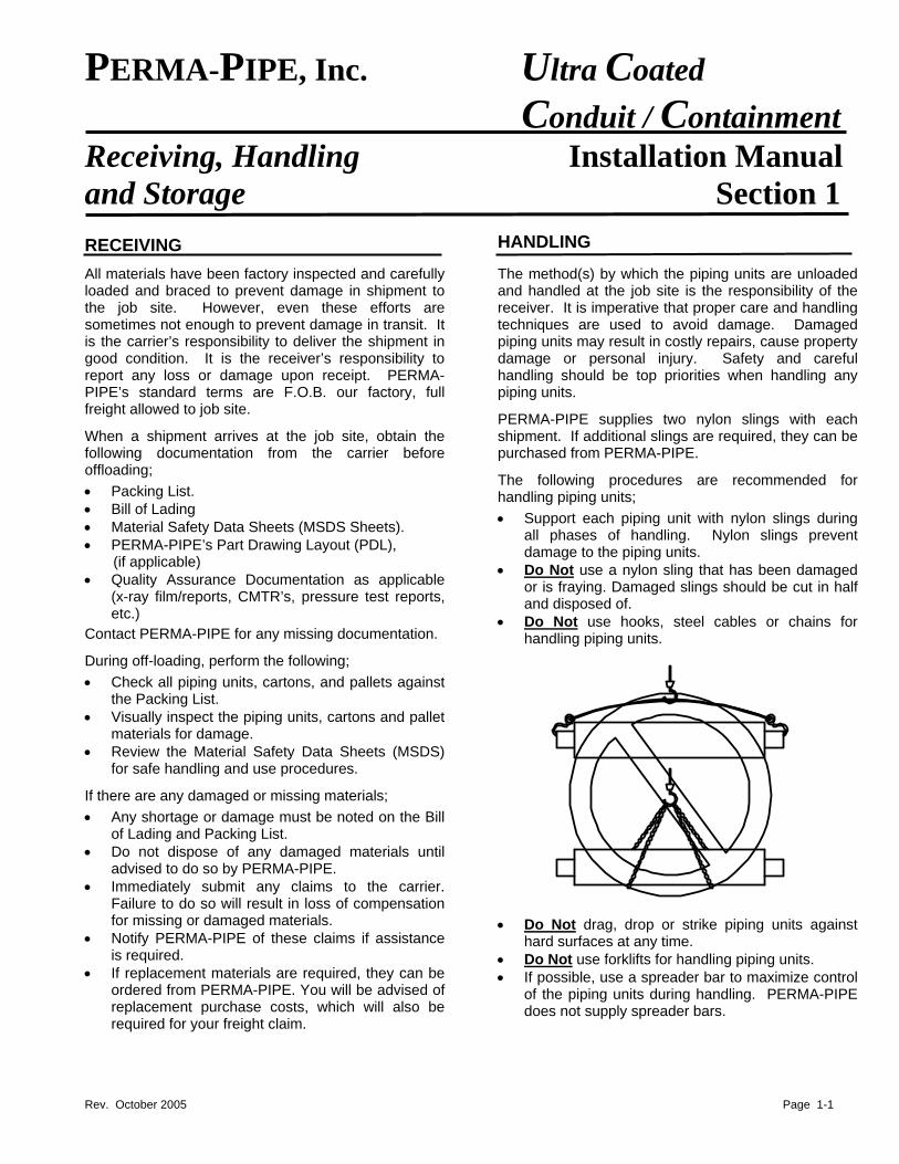
• Support each piping unit with nylon slings during all phases of handling. Nylon slings prevent damage to the piping units.
• Material Safety Data Sheets (MSDS Sheets). • PERMA-PIPE’s Part Drawing Layout (PDL), (if applicable) • Do Not use a nylon sling that has been damaged
or is fraying. Damaged slings should be cut in half and disposed of.
• Quality Assurance Documentation as applicable (x-ray film/reports, CMTR’s, pressure test reports, etc.) • Do Not use hooks, steel cables or chains for
handling piping units.
Contact PERMA-PIPE for any missing documentation.
During off-loading, perform the following;
• Check all piping units, cartons, and pallets against the Packing List.
• Visually inspect the piping units, cartons and pallet materials for damage.
• Review the Material Safety Data Sheets (MSDS) for safe handling and use procedures.
If there are any damaged or missing materials;
• Any shortage or damage must be noted on the Bill of Lading and Packing List.
• Do not dispose of any damaged materials until advised to do so by PERMA-PIPE.
• Immediately submit any claims to the carrier. Failure to do so will result in loss of compensation for missing or damaged materials.
• Do Not drag, drop or strike piping units against
hard surfaces at any time. • Notify PERMA-PIPE of these claims if assistance is required. • Do Not use forklifts for handling piping units.
• If replacement materials are required, they can be ordered from PERMA-PIPE. You will be advised of replacement purchase costs, which will also be required for your freight claim.
• If possible, use a spreader bar to maximize control of the piping units during handling. PERMA-PIPE does not supply spreader bars.
Rev. October 2005 Page 1-1
PERMA-PIPE, Inc. Ultra Coated Conduit / Containment
Receiving, Handling Installation Manual and Storage (cont.) Section 1 HANDLING (continued)
• Use two nylon slings where possible to provide much more control of the piping unit. A piping unit suspended with a single nylon sling is more likely to swing out of control, potentially causing a safety hazard.
• Space the slings approximately 15 - 20 feet apart
depending on the size of the piping unit. • If a piping unit is damaged during handling, refer to
Section 7 for repair recommendations.
SAFETY CONSIDERATIONS
Safety should always be a primary consideration when unloading and handling piping units.
• Never lift more weight than your equipment can safely handle.
• Never lift more weight than the rating of the slings. • Do Not use damaged slings. Cut up and dispose
of any damaged slings. • PERMA-PIPE chocks only the outer piping units in
each layer (or tier) on the truck. It is important to recognize that as you lift piping units off the truck, nearby piping units may become unstable and roll. Chock piping units that are not being unloaded.
STORAGE
Proper storage of piping units and loose shipped materials is very important. These materials can deteriorate or sustain damage if not properly stored. Proper storage is the responsibility of the receiver. The following procedures are recommended;
PIPING UNITS
• If possible, store the piping units in a warehouse or temperature controlled shelter. If this is not possible, store the piping units on high ground to avoid ingress of water into the pipe ends. Do Not allow water to accumulate in the conduit /
containment pipe as this may lead to corrosion of the conduit / containment pipe or service pipe.
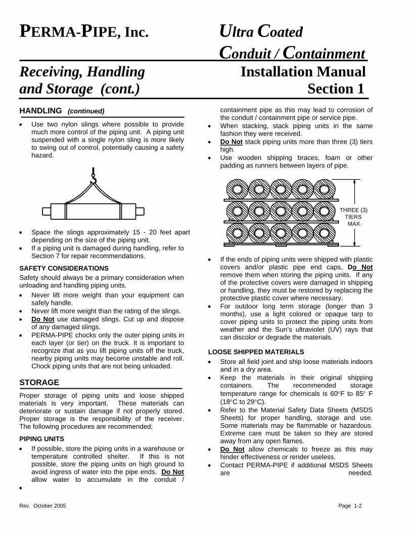
• When stacking, stack piping units in the same fashion they were received.
• Do Not stack piping units more than three (3) tiers high.
• Use wooden shipping braces, foam or other padding as runners between layers of pipe.
THREE (3)TIERSMAX.
• If the ends of piping units were shipped with plastic
covers and/or plastic pipe end caps, Do Not remove them when storing the piping units. If any of the protective covers were damaged in shipping or handling, they must be restored by replacing the protective plastic cover where necessary.
• For outdoor long term storage (longer than 3 months), use a light colored or opaque tarp to cover piping units to protect the piping units from weather and the Sun’s ultraviolet (UV) rays that can discolor or degrade the materials.
LOOSE SHIPPED MATERIALS
• Store all field joint and ship loose materials indoors and in a dry area.
• Keep the materials in their original shipping containers. The recommended storage temperature range for chemicals is 60°F to 85° F (18°C to 29°C).
• Refer to the Material Safety Data Sheets (MSDS Sheets) for proper handling, storage and use. Some materials may be flammable or hazardous. Extreme care must be taken so they are stored away from any open flames.
• Do Not allow chemicals to freeze as this may hinder effectiveness or render useless.
• Contact PERMA-PIPE if additional MSDS Sheets are needed.
•
Rev. October 2005 Page 1-2
PERMA-PIPE, Inc. Ultra Coated Conduit / Containment Excavation Installation Manual
Section 2
EXCAVATION
4" MIN. BEDDING
6" MIN.(TYP.)
TRENCH WIDTH
Underground conduit / containment pipe derives some of its strength from the passive soil resistance around it. Therefore, proper excavation and backfilling of the trench is very important to insure a structurally sound installed conduit / containment system.
ULTRA coated conduit / containment piping is designed to handle normal soil and H-20 traffic loading when the recommendations in this Installation Manual are followed and a minimum of 2 feet of properly compacted cover is provided. See Section 6 for backfilling and compaction recommendations.
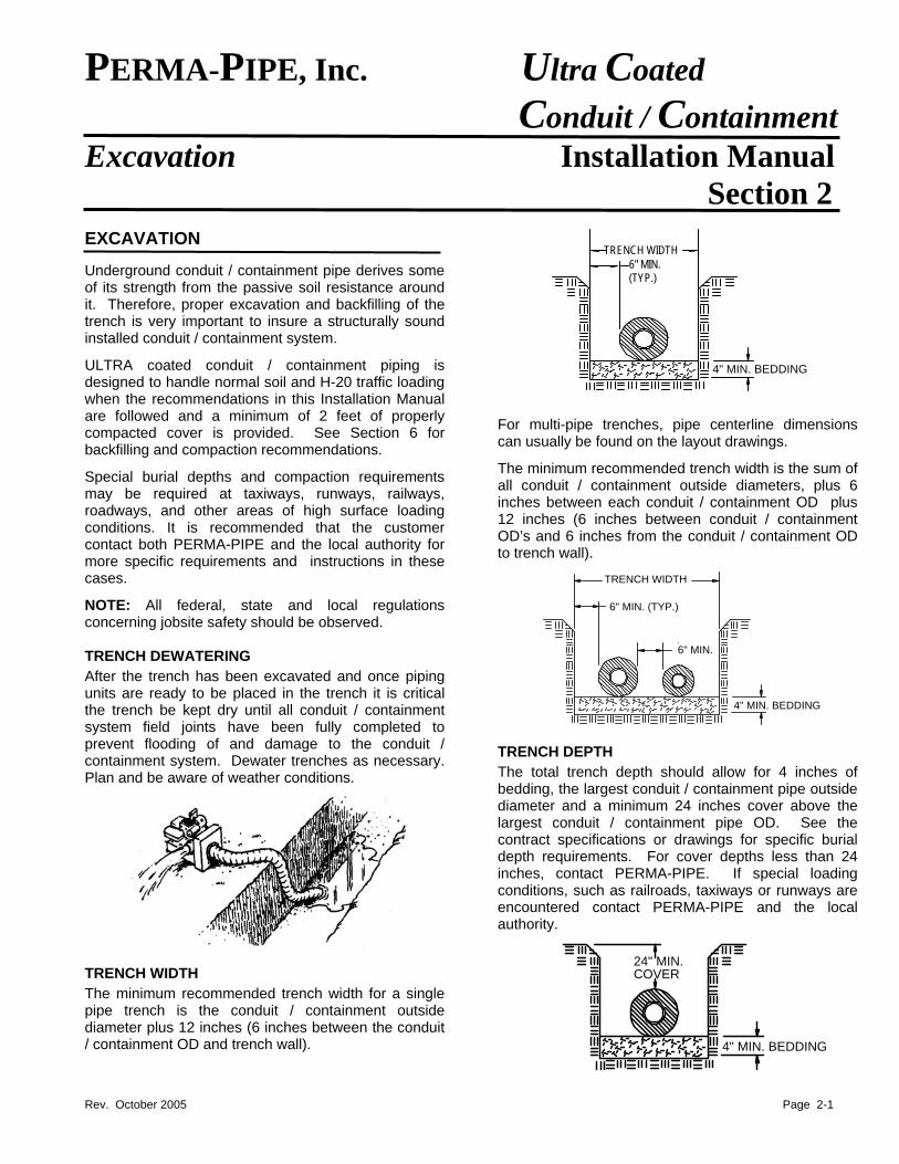
For multi-pipe trenches, pipe centerline dimensions can usually be found on the layout drawings.
The minimum recommended trench width is the sum of all conduit / containment outside diameters, plus 6 inches between each conduit / containment OD plus 12 inches (6 inches between conduit / containment OD’s and 6 inches from the conduit / containment OD to trench wall).
Special burial depths and compaction requirements may be required at taxiways, runways, railways, roadways, and other areas of high surface loading conditions. It is recommended that the customer contact both PERMA-PIPE and the local authority for more specific requirements and instructions in these cases.
6" MIN. (TYP.)
6" MIN.
4" MIN. BEDDING
TRENCH WIDTH
NOTE: All federal, state and local regulations concerning jobsite safety should be observed. TRENCH DEWATERING
After the trench has been excavated and once piping units are ready to be placed in the trench it is critical the trench be kept dry until all conduit / containment system field joints have been fully completed to prevent flooding of and damage to the conduit / containment system. Dewater trenches as necessary. Plan and be aware of weather conditions.
TRENCH DEPTH
The total trench depth should allow for 4 inches of bedding, the largest conduit / containment pipe outside diameter and a minimum 24 inches cover above the largest conduit / containment pipe OD. See the contract specifications or drawings for specific burial depth requirements. For cover depths less than 24 inches, contact PERMA-PIPE. If special loading conditions, such as railroads, taxiways or runways are encountered contact PERMA-PIPE and the local authority.
TRENCH WIDTH
The minimum recommended trench width for a single pipe trench is the conduit / containment outside diameter plus 12 inches (6 inches between the conduit / containment OD and trench wall).
24" MIN.COVER
4" MIN. BEDDING
Rev. October 2005 Page 2-1
PERMA-PIPE, Inc. Ultra Coated Conduit / Containment Excavation (cont.) Installation Manual
Section 2
TRENCH BEDDING
Clear the trench floor of stones and rocks and then cover with 4 inches of compacted bedding. Rake the bedding uniformly along the entire length of the trench and graded to a minimum slope of 1 inch per 40 feet to allow for gravity draining of the conduit / containment system.
Trench bedding material and compaction should be in accordance with the recommendations provided in Section 6. BELL HOLES
Digging bell holes at field joint locations allows room for service pipe and conduit / containment pipe joining, coating and testing. A common way to dig bell holes is to cut across the trench with a backhoe.
The bell holes should be cut into the trench wall and between 1½ and 2 feet below the trench floor. Bell hole locations should be identified and dug before lowering piping units into the trench.
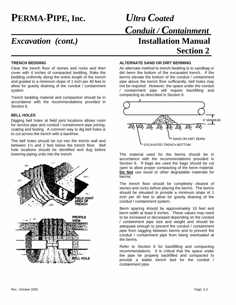
ALTERNATE SAND OR DIRT BERMING
An alternate method to trench bedding is to sandbag or dirt berm the bottom of the excavated trench. If the berms elevate the bottom of the conduit / containment pipe above the trench floor sufficiently, bell holes may not be required. However, the space under the conduit / containment pipe will require backfilling and compacting as described in Section 6.
EXCAVATED TRENCH BOTTOM
SAND OR DIRT BERM
4" MINIMUM
The material used for the berms should be in accordance with the recommendations provided in Section 6. If bags are used the bags should be cut open to allow proper compacting of the berm material. Do Not use wood or other degradable materials for berms.
The trench floor should be completely cleared of stones and rocks before placing the berms. The berms should be elevated to provide a minimum slope of 1 inch per 40 feet to allow for gravity draining of the conduit / containment system.
Berm spacing should be approximately 10 feet and berm width at least 6 inches. These values may need to be increased or decreased depending on the conduit / containment pipe size and weight and should be adequate enough to prevent the conduit / containment pipe from sagging between berms and to prevent the conduit / containment pipe from being overloaded at the berms.
Refer to Section 6 for backfilling and compacting recommendations. It is critical that the space under the pipe be properly backfilled and compacted to provide a stable trench bed for the conduit / containment pipe.
Rev. October 2005 Page 2-2
PERMA-PIPE, Inc. Ultra Coated Conduit / Containment Excavation (cont.) Installation Manual
Section 2
SPECIAL SOIL CONDITIONS
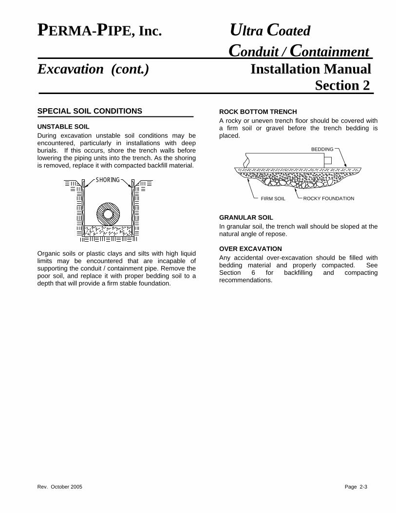
UNSTABLE SOIL
During excavation unstable soil conditions may be encountered, particularly in installations with deep burials. If this occurs, shore the trench walls before lowering the piping units into the trench. As the shoring is removed, replace it with compacted backfill material.
SHORING
Organic soils or plastic clays and silts with high liquid limits may be encountered that are incapable of supporting the conduit / containment pipe. Remove the poor soil, and replace it with proper bedding soil to a depth that will provide a firm stable foundation.
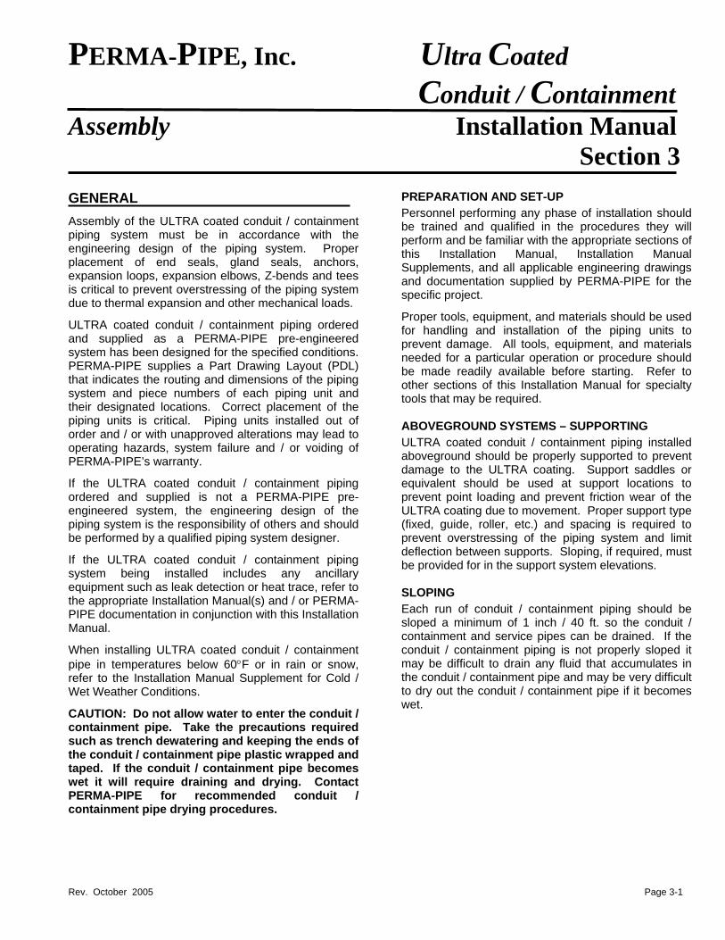
ROCK BOTTOM TRENCH
A rocky or uneven trench floor should be covered with a firm soil or gravel before the trench bedding is placed.
BEDDING
FIRM SOIL ROCKY FOUNDATION
GRANULAR SOIL
In granular soil, the trench wall should be sloped at the natural angle of repose. OVER EXCAVATION
Any accidental over-excavation should be filled with bedding material and properly compacted. See Section 6 for backfilling and compacting recommendations.
Rev. October 2005 Page 2-3
PERMA-PIPE, Inc. Ultra Coated Conduit / Containment Assembly Installation Manual
Section 3 GENERAL
Assembly of the ULTRA coated conduit / containment piping system must be in accordance with the engineering design of the piping system. Proper placement of end seals, gland seals, anchors, expansion loops, expansion elbows, Z-bends and tees is critical to prevent overstressing of the piping system due to thermal expansion and other mechanical loads.
ULTRA coated conduit / containment piping ordered and supplied as a PERMA-PIPE pre-engineered system has been designed for the specified conditions. PERMA-PIPE supplies a Part Drawing Layout (PDL) that indicates the routing and dimensions of the piping system and piece numbers of each piping unit and their designated locations. Correct placement of the piping units is critical. Piping units installed out of order and / or with unapproved alterations may lead to operating hazards, system failure and / or voiding of PERMA-PIPE’s warranty.
If the ULTRA coated conduit / containment piping ordered and supplied is not a PERMA-PIPE pre-engineered system, the engineering design of the piping system is the responsibility of others and should be performed by a qualified piping system designer.
If the ULTRA coated conduit / containment piping system being installed includes any ancillary equipment such as leak detection or heat trace, refer to the appropriate Installation Manual(s) and / or PERMA-PIPE documentation in conjunction with this Installation Manual.
When installing ULTRA coated conduit / containment pipe in temperatures below 60°F or in rain or snow, refer to the Installation Manual Supplement for Cold / Wet Weather Conditions.
CAUTION: Do not allow water to enter the conduit / containment pipe. Take the precautions required such as trench dewatering and keeping the ends of the conduit / containment pipe plastic wrapped and taped. If the conduit / containment pipe becomes wet it will require draining and drying. Contact PERMA-PIPE for recommended conduit / containment pipe drying procedures.
PREPARATION AND SET-UP
Personnel performing any phase of installation should be trained and qualified in the procedures they will perform and be familiar with the appropriate sections of this Installation Manual, Installation Manual Supplements, and all applicable engineering drawings and documentation supplied by PERMA-PIPE for the specific project.
Proper tools, equipment, and materials should be used for handling and installation of the piping units to prevent damage. All tools, equipment, and materials needed for a particular operation or procedure should be made readily available before starting. Refer to other sections of this Installation Manual for specialty tools that may be required. ABOVEGROUND SYSTEMS – SUPPORTING
ULTRA coated conduit / containment piping installed aboveground should be properly supported to prevent damage to the ULTRA coating. Support saddles or equivalent should be used at support locations to prevent point loading and prevent friction wear of the ULTRA coating due to movement. Proper support type (fixed, guide, roller, etc.) and spacing is required to prevent overstressing of the piping system and limit deflection between supports. Sloping, if required, must be provided for in the support system elevations. SLOPING
Each run of conduit / containment piping should be sloped a minimum of 1 inch / 40 ft. so the conduit / containment and service pipes can be drained. If the conduit / containment piping is not properly sloped it may be difficult to drain any fluid that accumulates in the conduit / containment pipe and may be very difficult to dry out the conduit / containment pipe if it becomes wet.
Rev. October 2005 Page 3-1
PERMA-PIPE, Inc. Ultra Coated Conduit / Containment Assembly (cont.) Installation Manual Section 3 PIPING UNIT LAYOUT
LOWERING / LIFTING
If sufficient handling equipment (multiple cranes, spreader bar, etc.) is available, it may be easier to complete some field joints before lowering piping units into the trench or lifting onto supports. This may require more than one crane and / or a spreader bar to lower or lift the joined piping units into place. Do Not allow joined piping units to bow when handling.
Piping units should be moved into place in the following manner;
• Remove all free standing water from trenches and bell holes before lowering piping units. Bell holes and trench bedding must be dry during piping unit installation. Dewater trenches as necessary.
• Lower or lift the piping units into place. Do Not drop the piping units. Spreader bars or more than one crane may be required depending on the size of the piping unit being handled.
• If the piping units have been supplied with end protection, Do Not remove the end protection materials until the service pipes are to be joined.
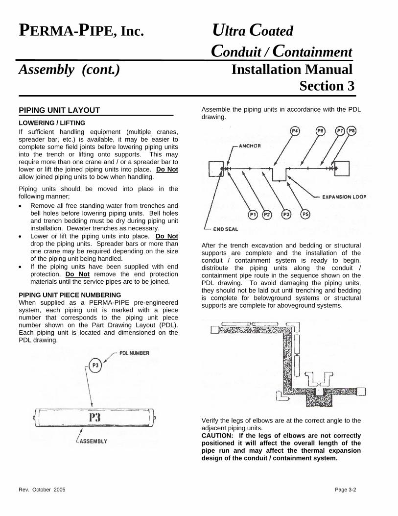
PIPING UNIT PIECE NUMBERING When supplied as a PERMA-PIPE pre-engineered system, each piping unit is marked with a piece number that corresponds to the piping unit piece number shown on the Part Drawing Layout (PDL). Each piping unit is located and dimensioned on the PDL drawing.
Assemble the piping units in accordance with the PDL drawing.
After the trench excavation and bedding or structural supports are complete and the installation of the conduit / containment system is ready to begin, distribute the piping units along the conduit / containment pipe route in the sequence shown on the PDL drawing. To avoid damaging the piping units, they should not be laid out until trenching and bedding is complete for belowground systems or structural supports are complete for aboveground systems.
Verify the legs of elbows are at the correct angle to the adjacent piping units. CAUTION: If the legs of elbows are not correctly positioned it will affect the overall length of the pipe run and may affect the thermal expansion design of the conduit / containment system.
Rev. October 2005 Page 3-2
Rev. October 2005 Page 3-3
PERMA-PIPE, Inc. Ultra Coated Conduit / Containment Assembly (cont.) Installation Manual Section 3
PIPING UNIT ORIENTATION
It is critical each piping unit is correctly orientated. In addition to piece numbers PERMA-PIPE proves the additional marking describe below to guide the proper orientation of piping units.
CAUTION: Special care must be taken when the ULTRA coated conduit / containment piping system includes leak detection or heat tracing because each pipe unit to pipe unit orientation is critical. See the appropriate Installation Manual Supplement(s).
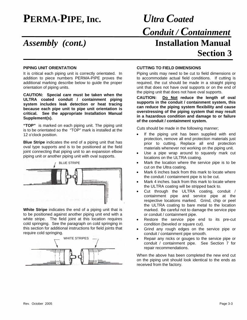
“TOP” is marked on each piping unit. The piping unit is to be orientated so the “TOP” mark is installed at the 12 o’clock position.
Blue Stripe indicates the end of a piping unit that has oval type supports and is to be positioned at the field joint connecting that piping unit to an expansion elbow piping unit or another piping unit with oval supports.
White Stripe indicates the end of a piping unit that is to be positioned against another piping unit end with a white stripe. The field joint at this location requires cold springing. See the paragraph on cold springing in this section for additional instructions for field joints that require cold springing.
CUTTING TO FIELD DIMENSIONS
Piping units may need to be cut to field dimensions or to accommodate actual field conditions. If cutting is required, the cut should be made in a straight piping unit that does not have oval supports or on the end of the piping unit that does not have oval supports.
CAUTION: Do Not reduce the length of oval supports in the conduit / containment system, this can reduce the piping system flexibility and cause overstressing of the piping system that may result in a hazardous condition and damage to or failure of the conduit / containment system.
Cuts should be made in the following manner;
• If the piping unit has been supplied with end protection, remove all end protection materials just prior to cutting. Replace all end protection materials whenever not working on the piping unit.
• Use a pipe wrap around to squarely mark cut locations on the ULTRA coating.
• Mark the location where the service pipe is to be cut on the Ultra coating.
BLUE STRIPE
• Mark 6 inches back from this mark to locate where the conduit / containment pipe is to be cut.
• Mark 4 inches. back from this mark to locate where the ULTRA coating will be stripped back to.
• Cut through the ULTRA coating, conduit / containment pipe and service pipe at the respective locations marked. Grind, chip or peel the ULTRA coating to bare metal to the location marked. Be careful not to damage the service pipe or conduit / containment pipe.
• Restore the service pipe end to its pre-cut condition (beveled or square cut).
• Grind any rough edges on the service pipe or conduit / containment pipe smooth.
WHITE STRIPES • Repair any nicks or gouges to the service pipe or conduit / containment pipe. See Section 7 for repair recommendations.
When the above has been completed the new end cut on the piping unit should look identical to the ends as received from the factory.
Rev. October 2005
PERMA-PIPE, Inc. Ultra Coated Conduit / Containment Assembly (cont.) Installation Manual Section 3
FIELD JOINTS
Special care is required at field joints that have white and blue stripes on the end of the piping units. See the Blue Stripe and White Stripe sections in the PIPING UNIT ORIENTATION section above for additional information.
Field joints that have offset service pipe at the field joint must have the service pipe offsetting maintained. See the SERVICE PIPE OFFSETTING section on the following pages for additional information before proceeding.
Field joints that required cold springing are designated by a white stripe and require cold springing. These field joints should be completed after all other field joints in the run of pipe are completed. See the SERVICE PIPE COLD SPRINGING section on the following pages for additional information before proceeding. SERVICE PIPE JOINING
If service pipe steel pipe socketweld couplings or copper pipe braze joint couplings are required they are supplied by the installer, they are not supplied by Perma-Pipe. The coupling gap dimensions are taken into account in the piping unit fabrication dimensions.
SteePipe Size
SocketWeld
1/43/8 1/23/41
1 1/41 1/2
2 All service pipe following manne
• If the pipinprotection, reprior to weld
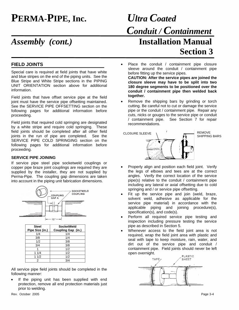
• Place the conduit / containment pipe closure sleeve around the conduit / containment pipe before fitting up the service pipes. CAUTION: After the service pipes are joined the closure sleeve may have to be split into two 180 degree segments to be positioned over the conduit / containment pipe then welded back together.
• Remove the shipping bars by grinding or torch cutting. Be careful not to cut or damage the service pipe or the conduit / containment pipe. Repair any cuts, nicks or gouges to the service pipe or conduit / containment pipe. See Section 7 for repair recommendations.
REMOVE SHIPPING BARS
CLOSURE SLEEVE
• Properly align and position each field joint. Verify
the legs of elbows and tees are at the correct angles. Verify the correct location of the service pipe(s) relative to the conduit / containment pipe including any lateral or axial offsetting due to cold springing and / or service pipe offsetting.
• Fit up the service pipe and join (weld, braze, solvent weld, adhesive as applicable for the service pipe material) in accordance with the applicable piping and joining procedure(s), specification(s), and code(s).
• Perform all required service pipe testing and inspection including pressure testing the service pipe as described in Section 5.
lPage 3-4
(in.) Coupling Gap (in.) 1/4 1/4 3/8 3/8
1/2 1/2 1/2
3/4
field joints should be completed in the r: g unit has been supplied with end move all end protection materials just
ing.
• Whenever access to the field joint area is not required, wrap the field joint area with plastic and seal with tape to keep moisture, rain, water, and dirt out of the service pipe and conduit / containment pipe. Field joints should never be left open overnight.
PERMA-PIPE, Inc. Ultra Coated Conduit / Containment Assembly (cont.) Installation Manual Section 3 SERVICE PIPE INSULATION
Conduit / containment systems with insulated service pipe(s) require the service pipe(s) to be field insulated at the field joint. High temperature conduit / containment systems may use two insulation layers with staggered seams between the insulation layers.
The field joint insulation material and stainless steel banding for securing the insulation in place are supplied by PERMA-PIPE.
Do Not install the field joint insulation until all service pipe joining, inspection and testing has been completed.
Insulate the field joint area in the following manner;
Measure the length of insulation required and cut the insulation to the required length. For double layer insulation systems cut each insulation layer to the required length.
Position the insulation over the service pipe and firmly band in place using the stainless steel banding provided.
For double layer insulation systems stagger the longitudinal and circumferential seams between layers.
Check the field joint insulation for any gaps. Fill any gaps with insulation and secure in place.
CONDUIT / CONTAINMENT PIPE CLOSURE SLEEVES
After completion of all required service pipe testing and inspection including pressure testing of the service pipe, each field joint requires installation and welding of the conduit / containment pipe closure sleeve.
NOTE: For ULTRA coated conduit / containment piping equipped with cable leak detection refer to the PAL-AT Installation Manual for instructions on the installation of the continuous leak detection pull cable. Do Not proceed with the conduit / containment pipe closure sleeve installation until the continuous pull cable has been properly installed.
There are two types of conduit / containment pipe closure sleeves – rolled and overlapped and butt weld. Rolled and overlapped closure sleeves are standard. Butt weld closure sleeves are supplied when the conduit / containment pipe wall is greater than ¼” or when the conduit / containment pipe is specially design for high pressure (greater than 15 psig).
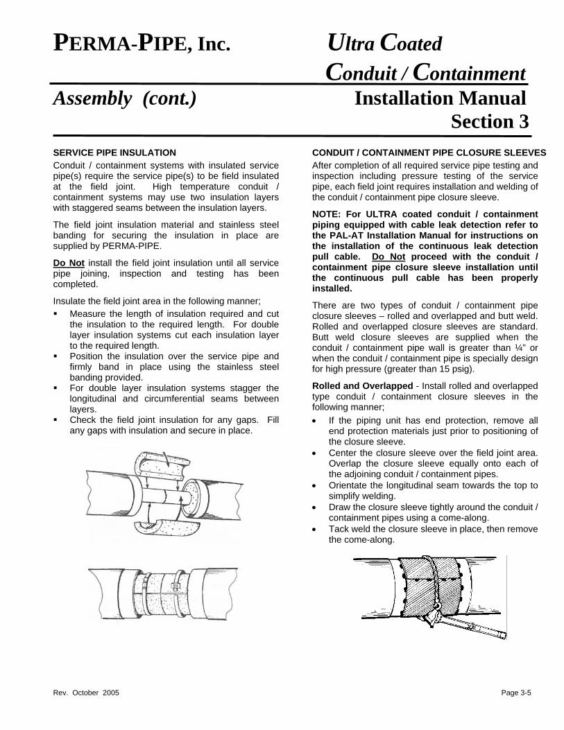
Rolled and Overlapped - Install rolled and overlapped type conduit / containment closure sleeves in the following manner;
• If the piping unit has end protection, remove all end protection materials just prior to positioning of the closure sleeve.
• Center the closure sleeve over the field joint area. Overlap the closure sleeve equally onto each of the adjoining conduit / containment pipes.
• Orientate the longitudinal seam towards the top to simplify welding.
• Draw the closure sleeve tightly around the conduit / containment pipes using a come-along.
• Tack weld the closure sleeve in place, then remove the come-along.
Rev. October 2005 Page 3-5
Rev. October 2005
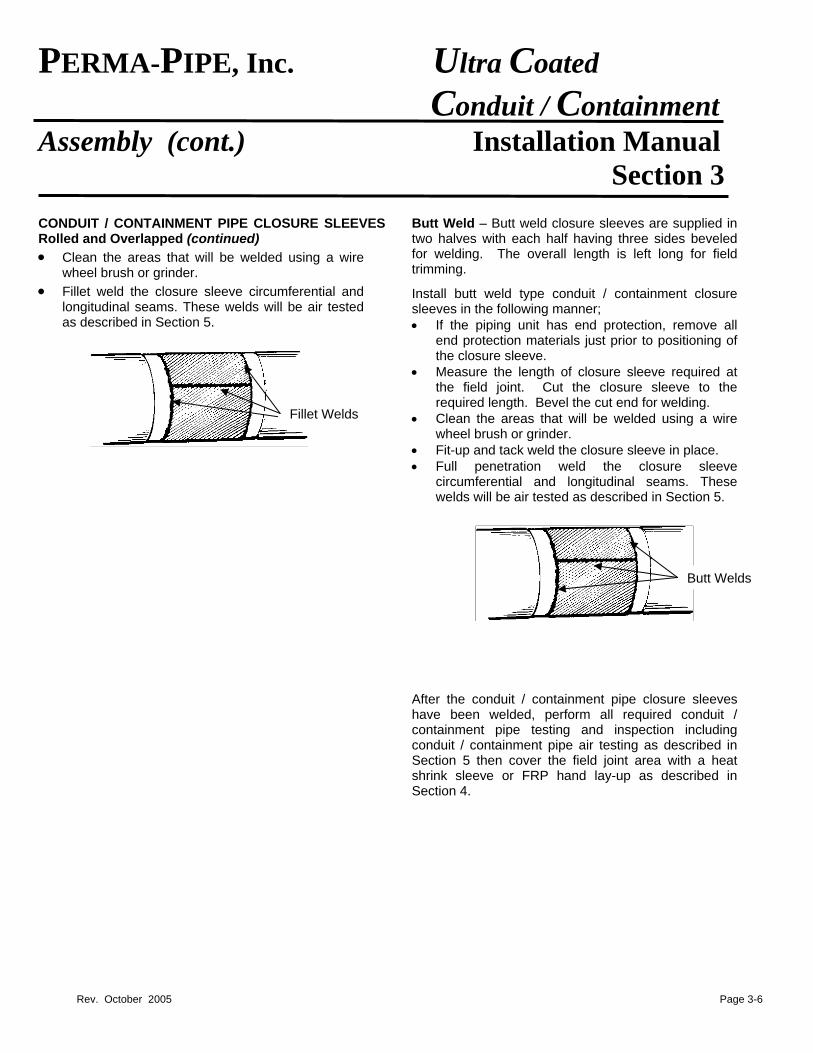
PERMA-PIPE, Inc. Ultra Coated Conduit / Containment Assembly (cont.) Installation Manual Section 3 CONDUIT / CONTAINMENT PIPE CLOSURE SLEEVES Rolled and Overlapped (continued) • Clean the areas that will be welded using a wire
wheel brush or grinder. • Fillet weld the closure sleeve circumferential and
longitudinal seams. These welds will be air tested as described in Section 5.
Butt Weld – Butt weld closure sleeves are supplied in two halves with each half having three sides beveled for welding. The overall length is left long for field trimming.
Install butt weld type conduit / containment closure sleeves in the following manner; • If the piping unit has end protection, remove all
end protection materials just prior to positioning of the closure sleeve.
• Measure the length of closure sleeve required at the field joint. Cut the closure sleeve to the required length. Bevel the cut end for welding.
s • Clean the areas that will be welded using a wire wheel brush or grinder.
• Fit-up and tack weld the closure sleeve in place. • Full penetration weld the closure sleeve
circumferential and longitudinal seams. These welds will be air tested as described in Section 5.
After the conduit / containment pipe closurhave been welded, perform all required containment pipe testing and inspection conduit / containment pipe air testing as deSection 5 then cover the field joint area wishrink sleeve or FRP hand lay-up as desSection 4.
Butt Welds
Fillet Weld
Page 3-6
e sleeves conduit / including
scribed in th a heat cribed in
PERMA-PIPE, Inc. Ultra Coated Conduit / Containment Assembly (cont.) Installation Manual Section 3
SERVICE PIPE OFFSETTING AND COLD SPRINGING
To efficiently accommodate thermal expansion of the service pipe within the conduit / containment pipe the service pipe may be offset within the conduit / containment pipe or may require cold springing at specific locations. This offsetting or cold springing is shown on the PDL drawing.
CAUTION: It is critical the conduit / containment system is installed with the correct service pipe offsetting and / or cold springing as shown on the PDL drawing. If the service pipe is not correctly offset or cold sprung the service pipe, insulation and / or conduit / containment pipe can be damaged or fail due to thermal expansion of the service pipe.
SERVICE PIPE OFFSETTING
Offsetting is typically built into the piping units effected unless specifically noted on the PDL as requiring field offsetting.
When assembling the piping units it is critical the offsetting is maintained, or if lost, restored. When shipping bars are cut loose the service pipe is free to move relative to the conduit / containment pipe and the offset dimension can change if care is not exercised. Field joints where the service pipe is offset should be checked for the correct amount of offset prior to completion of the field joint.
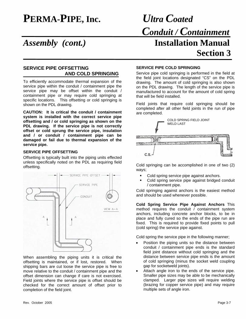
SERVICE PIPE COLD SPRINGING
Service pipe cold springing is performed in the field at the field joint locations designated “CS” on the PDL drawing. The amount of cold springing is also shown on the PDL drawing. The length of the service pipe is manufactured to account for the amount of cold spring that will be field installed.
Field joints that require cold springing should be completed after all other field joints in the run of pipe are completed.
Cold springing cways;
Cold sprin Cold sprin
/ containm
Cold springing aand should be u Cold Spring Smethod requireanchors, includiplace and fully fixed. This is r(cold spring) the Cold spring the s
• Position theconduit / cofield joint didistance betof cold springap for sock
• Attach angleSmaller pipeclamped. L(brazing for multiple sets
Rev. October 2005
COLD SPRING FIELD JOINTWELD LAST
an be accomplished in one of two (2)
g service pipe against anchors. g service pipe against bridged conduit ent pipe. gainst anchors is the easiest method
sed whenever possible.
ervice Pipe Against Anchors This s the conduit / containment system ng concrete anchor blocks, to be in cured so the ends of the pipe run are equired to provide fixed points to pull service pipe against.
ervice pipe in the following manner; piping units so the distance between ntainment pipe ends is the standard stance without cold springing and the ween service pipe ends is the amount ging (minus the socket weld coupling etweld joints). iron to the ends of the service pipe. sizes may be able to be mechanically arger pipe sizes will require welding copper service pipe) and may require of angle iron.
Page 3-7
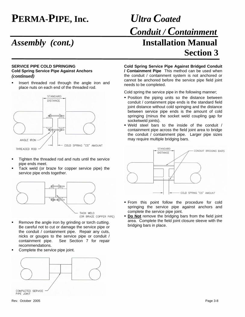
PERMA-PIPE, Inc. Ultra Coated Conduit / Containment Assembly (cont.) Installation Manual Section 3 SERVICE PIPE COLD SPRINGING Cold Spring Service Pipe Against Anchors (continued)
Insert threaded rod through the angle iron and place nuts on each end of the threaded rod.
Tighten the threaded rod and nuts until the service
pipe ends meet. Tack weld (or braze for copper service pipe) the
service pipe ends together.
Remove the angle iron by grinding or torch cutting. Be careful not to cut or damage the service pipe or the conduit / containment pipe. Repair any cuts, nicks or gouges to the service pipe or conduit / containment pipe. See Section 7 for repair recommendations.
Complete the service pipe joint.
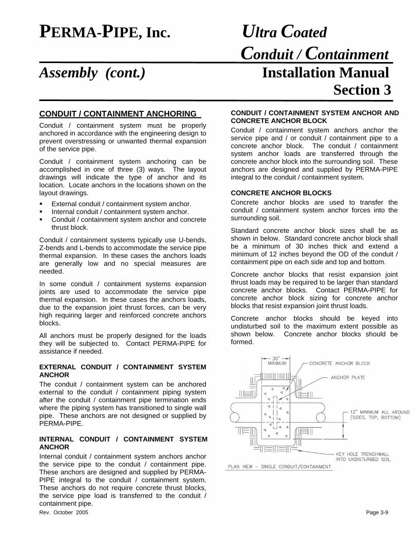
Cold Spring Service Pipe Against Bridged Conduit / Containment Pipe This method can be used when the conduit / containment system is not anchored or cannot be anchored before the service pipe field joint needs to be completed.
Cold spring the service pipe in the following manner;
Position the piping units so the distance between conduit / containment pipe ends is the standard field joint distance without cold springing and the distance between service pipe ends is the amount of cold springing (minus the socket weld coupling gap for socketweld joints).
Weld steel bars to the inside of the conduit / containment pipe across the field joint area to bridge the conduit / containment pipe. Larger pipe sizes may require multiple bridging bars.
From this point follow the procedure for cold springing the service pipe against anchors and complete the service pipe joint.
Do Not remove the bridging bars from the field joint area. Complete the field joint closure sleeve with the bridging bars in place.
Rev. October 2005 Page 3-8
PERMA-PIPE, Inc. Ultra Coated Conduit / Containment Assembly (cont.) Installation Manual Section 3
CONDUIT / CONTAINMENT ANCHORING
Conduit / containment system must be properly anchored in accordance with the engineering design to prevent overstressing or unwanted thermal expansion of the service pipe.
Conduit / containment system anchoring can be accomplished in one of three (3) ways. The layout drawings will indicate the type of anchor and its location. Locate anchors in the locations shown on the layout drawings.
External conduit / containment system anchor. Internal conduit / containment system anchor. Conduit / containment system anchor and concrete
thrust block.
Conduit / containment systems typically use U-bends, Z-bends and L-bends to accommodate the service pipe thermal expansion. In these cases the anchors loads are generally low and no special measures are needed.
In some conduit / containment systems expansion joints are used to accommodate the service pipe thermal expansion. In these cases the anchors loads, due to the expansion joint thrust forces, can be very high requiring larger and reinforced concrete anchors blocks.
All anchors must be properly designed for the loads they will be subjected to. Contact PERMA-PIPE for assistance if needed. EXTERNAL CONDUIT / CONTAINMENT SYSTEM ANCHOR
The conduit / containment system can be anchored external to the conduit / containment piping system after the conduit / containment pipe termination ends where the piping system has transitioned to single wall pipe. These anchors are not designed or supplied by PERMA-PIPE. INTERNAL CONDUIT / CONTAINMENT SYSTEM ANCHOR
Internal conduit / containment system anchors anchor the service pipe to the conduit / containment pipe. These anchors are designed and supplied by PERMA-PIPE integral to the conduit / containment system. These anchors do not require concrete thrust blocks, the service pipe load is transferred to the conduit / containment pipe.
CONDUIT / CONTAINMENT SYSTEM ANCHOR AND CONCRETE ANCHOR BLOCK
Conduit / containment system anchors anchor the service pipe and / or conduit / containment pipe to a concrete anchor block. The conduit / containment system anchor loads are transferred through the concrete anchor block into the surrounding soil. These anchors are designed and supplied by PERMA-PIPE integral to the conduit / containment system. CONCRETE ANCHOR BLOCKS
Concrete anchor blocks are used to transfer the conduit / containment system anchor forces into the surrounding soil.
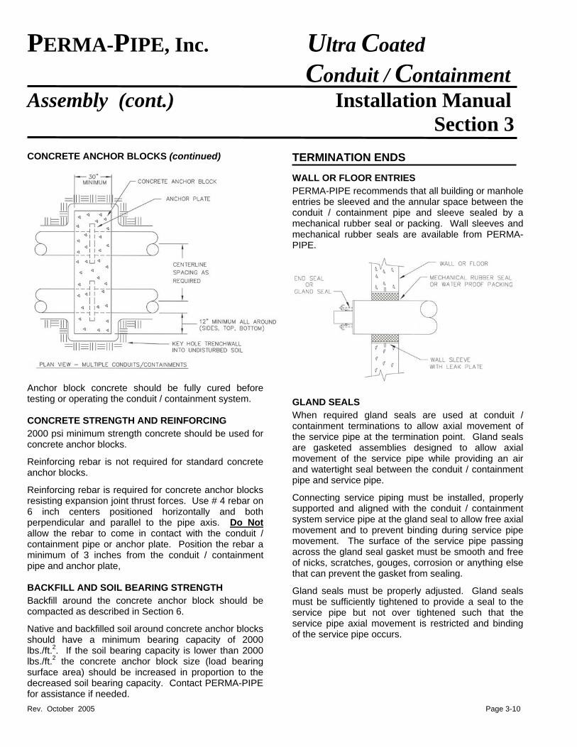
Standard concrete anchor block sizes shall be as shown in below. Standard concrete anchor block shall be a minimum of 30 inches thick and extend a minimum of 12 inches beyond the OD of the conduit / containment pipe on each side and top and bottom.
Concrete anchor blocks that resist expansion joint thrust loads may be required to be larger than standard concrete anchor blocks. Contact PERMA-PIPE for concrete anchor block sizing for concrete anchor blocks that resist expansion joint thrust loads.
Concrete anchor blocks should be keyed into undisturbed soil to the maximum extent possible as shown below. Concrete anchor blocks should be formed.
Rev. October 2005 Page 3-9
PERMA-PIPE, Inc. Ultra Coated Conduit / Containment Assembly (cont.) Installation Manual Section 3
CONCRETE ANCHOR BLOCKS (continued)
Anchor block concrete should be fully cured before testing or operating the conduit / containment system. CONCRETE STRENGTH AND REINFORCING
2000 psi minimum strength concrete should be used for concrete anchor blocks.
Reinforcing rebar is not required for standard concrete anchor blocks.
Reinforcing rebar is required for concrete anchor blocks resisting expansion joint thrust forces. Use # 4 rebar on 6 inch centers positioned horizontally and both perpendicular and parallel to the pipe axis. Do Not allow the rebar to come in contact with the conduit / containment pipe or anchor plate. Position the rebar a minimum of 3 inches from the conduit / containment pipe and anchor plate, BACKFILL AND SOIL BEARING STRENGTH
Backfill around the concrete anchor block should be compacted as described in Section 6.
Native and backfilled soil around concrete anchor blocks should have a minimum bearing capacity of 2000 lbs./ft.2. If the soil bearing capacity is lower than 2000 lbs./ft.2 the concrete anchor block size (load bearing surface area) should be increased in proportion to the decreased soil bearing capacity. Contact PERMA-PIPE for assistance if needed.
TERMINATION ENDS WALL OR FLOOR ENTRIES
PERMA-PIPE recommends that all building or manhole entries be sleeved and the annular space between the conduit / containment pipe and sleeve sealed by a mechanical rubber seal or packing. Wall sleeves and mechanical rubber seals are available from PERMA-PIPE.
GLAND SEALS
When required gland seals are used at conduit / containment terminations to allow axial movement of the service pipe at the termination point. Gland seals are gasketed assemblies designed to allow axial movement of the service pipe while providing an air and watertight seal between the conduit / containment pipe and service pipe.
Connecting service piping must be installed, properly supported and aligned with the conduit / containment system service pipe at the gland seal to allow free axial movement and to prevent binding during service pipe movement. The surface of the service pipe passing across the gland seal gasket must be smooth and free of nicks, scratches, gouges, corrosion or anything else that can prevent the gasket from sealing.
Gland seals must be properly adjusted. Gland seals must be sufficiently tightened to provide a seal to the service pipe but not over tightened such that the service pipe axial movement is restricted and binding of the service pipe occurs.
Rev. October 2005 Page 3-10
Rev. October 2005 Page 3-11
PERMA-PIPE, Inc. Ultra Coated Conduit / Containment Assembly (cont.) Installation Manual Section 3 GLAND SEALS (continued)
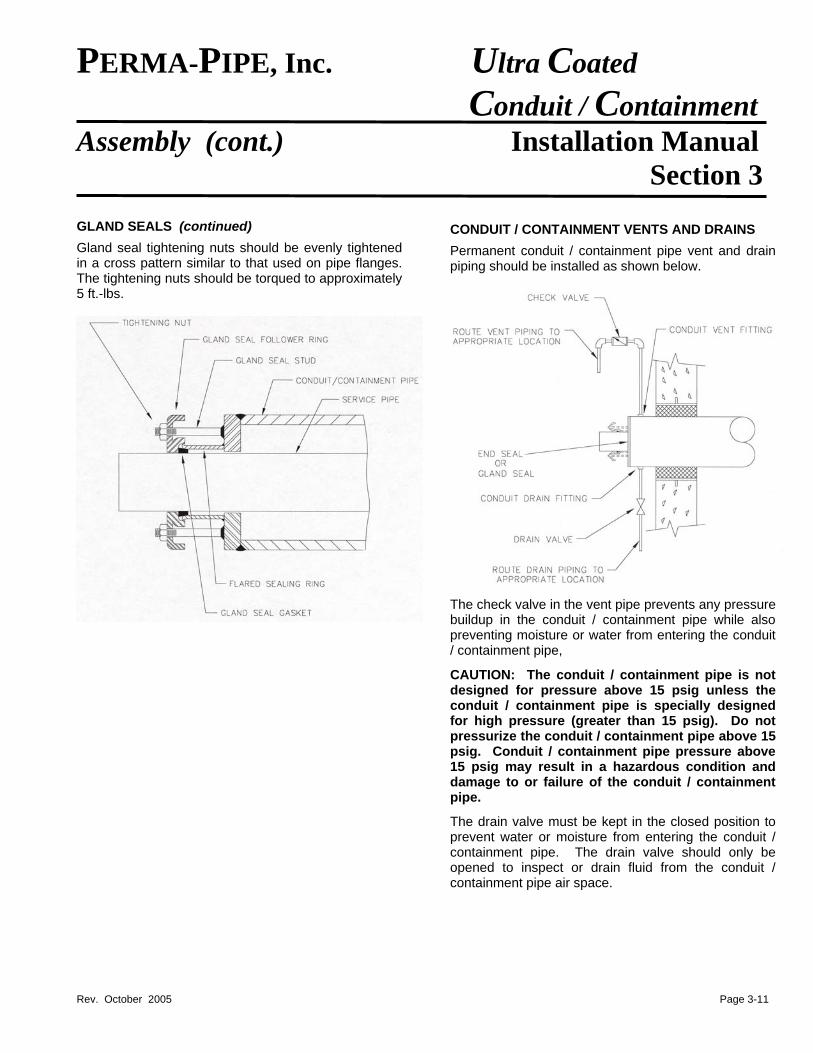
Gland seal tightening nuts should be evenly tightened in a cross pattern similar to that used on pipe flanges. The tightening nuts should be torqued to approximately 5 ft.-lbs.
CONDUIT / CONTAINMENT VENTS AND DRAINS
Permanent conduit / containment pipe vent and drain piping should be installed as shown below.
The check valve in the vent pipe prevents any pressure buildup in the conduit / containment pipe while also preventing moisture or water from entering the conduit / containment pipe,
CAUTION: The conduit / containment pipe is not designed for pressure above 15 psig unless the conduit / containment pipe is specially designed for high pressure (greater than 15 psig). Do not pressurize the conduit / containment pipe above 15 psig. Conduit / containment pipe pressure above 15 psig may result in a hazardous condition and damage to or failure of the conduit / containment pipe.
The drain valve must be kept in the closed position to prevent water or moisture from entering the conduit / containment pipe. The drain valve should only be opened to inspect or drain fluid from the conduit / containment pipe air space.
PERMA-PIPE, Inc. Ultra Coated Conduit / Containment Alterations and Installation Manual Repairs Section 7
ALTERATIONS REPAIRS
ULTRA COATING REPAIRS - GENERAL When alterations to an ULTRA coated conduit / containment piping system are necessary, the considerations herein are recommended. Alterations should be performed using the appropriate installation recommendations described in other sections of this Installation Manual.
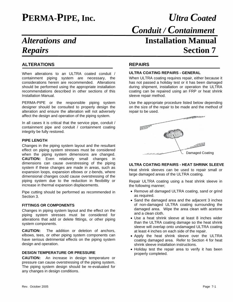
When ULTRA coating requires repair, either because it has not passed a holiday test or it has been damaged during shipment, installation or operation the ULTRA coating can be repaired using an FRP or heat shrink sleeve repair method.
PERMA-PIPE or the responsible piping system designer should be consulted to properly design the alteration and ensure the alteration will not adversely affect the design and operation of the piping system.
Use the appropriate procedure listed below depending on the size of the repair to be made and the method of repair to be used.
In all cases it is critical that the service pipe, conduit / containment pipe and conduit / containment coating integrity be fully restored. PIPE LENGTH
Changes in the piping system layout and the resultant effect on piping system stresses must be considered when the piping system dimensions are changed. CAUTION: Even relatively small changes in dimensions can cause overstressing of the piping system if these changes are made in areas, such as expansion loops, expansion elbows or z-bends, where dimensional changes could cause overstressing of the piping system due to the reduction in flexibility or increase in thermal expansion displacements.
Damaged Coating
ULTRA COATING REPAIRS - HEAT SHRINK SLEEVE
Heat shrink sleeves can be used to repair small or large damaged areas of the ULTRA coating.
Repair ULTRA coating using a heat shrink sleeve in the following manner;
• Remove all damaged ULTRA coating, sand or grind as required.
Pipe cutting should be performed as recommended in Section 3.
• Sand the damaged area and the adjacent 3 inches of non-damaged ULTRA coating surrounding the damaged area. Wipe the area clean with acetone and a clean cloth.
FITTINGS OR COMPONENTS
Changes in piping system layout and the effect on the piping system stresses must be considered for alterations that add or delete fittings, or other piping system components.
• Use a heat shrink sleeve at least 8 inches wider than the ULTRA coating damage so the heat shrink sleeve will overlap onto undamaged ULTRA coating at least 4 inches on each side of the repair.
CAUTION: The addition or deletion of anchors, elbows, tees, or other piping system components can have serious detrimental effects on the piping system design and operation.
• Apply the heat shrink sleeve over the ULTRA coating damaged area. Refer to Section 4 for heat shrink sleeve installation instructions.
• Holiday test the repair area to verify it has been properly completed. DESIGN TEMPERATURE OR PRESSURE
CAUTION: An increase in design temperature or pressure can cause overstressing of the piping system. The piping system design should be re-evaluated for any changes in design conditions.
Rev. October 2005 Page 7-1
PERMA-PIPE, Inc. Ultra Coated Conduit / Containment Alterations and Installation Manual Repairs (cont.) Section 7 ULTRA COATING REPAIRS - PINHOLE WITH FRP RESIN
Pinhole damage to ULTRA coating is typically found only by holiday testing. Since the size of this type of damage is less than 1/8 inch, only polyester resin is required to make this type of repair.
NOTE: Due to the extremely small nature of this type of repair and the small amount of resin required, it maybe easier to make this repair in conjunction with other repairs or a field joint FRP hand lay-up.
Repair ULTRA coating pinholes in the following manner;
• Sand a 2 inch diameter area with the pinhole in the center. Wipe the area clean with acetone and a clean cloth.
• Measure one cup of promoted polyester resin into a separate mixing pail, adding the required amount of catalyst. See Section 4 for measuring and mixing instructions.
• Brush a heavy layer of catalyzed resin onto the repair area. Let the repair cure for at least 24 hours.
• Holiday test the repair area to verify it has been properly completed.
ULTRA COATING REPAIRS - SMALL (< 4 INCH DIA.) WITH FRP HAND LAY-UP
Small ULTRA coating repairs require two layers of resin saturated bi-ply mat, but not a complete wrap-around of the conduit / containment pipe. Typically, the largest diameter of bi-ply mat that can easily be worked by one person is about 10 inches.
Make small ULTRA coating repairs in the following manner;
• Sand the damaged area and the adjacent 3 inches of non-damaged ULTRA coating surrounding the damaged area. Wipe the area clean with acetone and a clean cloth.
• Cut two pieces of fiberglass bi-ply mat, each large enough to cover the sanded area.
• Measure one quart of promoted polyester resin into a separate mixing pail, adding the required amount of catalyst. See Section 4 for measuring and mixing instructions.
• Pour one fourth (¼) of the catalyzed resin onto the repair area and spread with a brush.
• Lay a piece of bi-ply mat, chopped glass side facing down, onto the repair area. Pour one half (½) of the remaining resin onto the bi-ply mat. Roll out the bi-ply mat until it appears transparent.
• Lay the second piece of bi-ply mat onto the first piece, chopped glass side facing down. Pour the remaining resin onto the bi-ply mat. Roll out until it appears transparent and any trapped air has been pushed out.
• Let the hand lay-up repair cure for at least 24 hours.
• Holiday test the repair area to verify it has been properly complete.
ULTRA COATING REPAIRS - LARGE (> 4 INCH DIA.) WITH FRP HAND LAY-UP
Large ULTRA coating repairs typically require more extensive preparation and a complete FRP hand lay-up wrapped around the conduit / containment pipe. The damaged area must be prepared with either a sander or grinder. Detached and / or heavily damaged ULTRA coating must be ground off.
Make large ULTRA coating repairs in the following manner;
• Grind and / or sand the damaged area to remove all damaged and loose ULTRA coating.
• Sand the damaged area and the adjacent 3 inches of non-damaged ULTRA coating surrounding the damaged area. Wipe the area clean with acetone and a clean cloth.
• The bi-ply matt needs to be wide enough to cover the damaged area, plus a minimum 4 inches on each side. If required, cut the bi-ply mat width to 8 inches wider than the repair area.
• The balance of the repair procedure is now the same as the field joint FRP hand lay-up procedure. Follow the instructions in Section 4. Adjust the amount of resin proportionately for the width of the bi-ply mat if it has been cut.
• After completing the repair, let the FRP hand lay-up repair cure for at least 24 hours.
• Holiday test the repair area to verify it has been properly completed.
Rev. October 2005 Page 7-2
PERMA-PIPE, Inc. Ultra Coated Conduit / Containment Alterations and Installation Manual Repairs (cont.) Section 7 CONDUIT / CONTAINMENT PIPE REPAIRS
Conduit / containment pipe that has damage to its leak tight capability requires repair or replacement to prevent water from entering the conduit / containment pipe or fluid from escaping from the conduit / containment pipe.
If the conduit / containment pipe is repaired, the repair method must restore the conduit / containment to leak tight condition and the ULTRA coating must be repaired or restored in the areas that have been repaired. SERVICE PIPE REPAIRS
Do Not operate a service pipe that has damage to its pressure retaining capability.
Service pipe damage such as gouges, dents, cracks, bending, or flattening requires repair or replacement of the service pipe.
If the service pipe is repaired, the repair method must restore the full pressure retaining capability to the service pipe. GLAND SEAL REPAIRS
Any nicks, scratches, gouges or corrosion on the surface of the service pipe that passes across the gland seal gasket must be repaired so the service pipe surface is smooth and will seal against the gland seal gasket.
Gland seal gaskets that are worn or damaged must be replaced. Contact PERMA-PIPE for replacement gland seal gaskets. To install a replacement gland seal gasket around an installed service pipe, cut the gasket at a sharp angle (45 degrees or greater) and install into the gland seal.
WET CONDUIT / CONTAINMENT PIPE
Any water or fluid accumulation in the conduit / containment pipe must be removed immediately to prevent corrosion of the service and conduit / containment pipes from continuing or occurring.
Drain all fluid from the conduit / containment pipe then dry out the conduit / containment pipe. Contact PERMA-PIPE for recommended conduit / containment pipe dry out procedures.
CAUTION: ULTRA coated conduit / containment pipe can be used for many different process fluid applications. It is the user’s responsibility to employ the proper precautions for the process fluid being used.
Rev. October 2005 Page 7-3
PERMA-PIPE, Inc. Ultra Coated Conduit / Containment
Backfilling Installation Manual Section 6
BACKFILLING
Underground conduit / containment pipe derives some of its strength from the passive soil resistance around it. Therefore, proper backfilling of the trench is very important to insure a structurally sound installed conduit / containment system.
ULTRA coated conduit / containment piping is designed to handle normal soil and H20 traffic loading when these recommendations are followed and a minimum of 2 feet of properly compacted backfill is provided
If these recommendations conflict with the project contract specifications or drawings or PERMA-PIPE’S engineering drawings, the more stringent requirements should take precedence. If in doubt, contact the PERMA-PIPE Project Engineer, Project Manager or Field Technical Representative. Any deviations from these recommendations or PERMA-PIPE’S engineering drawings should be reviewed with the appropriate PERMA-PIPE personnel. HIGH SURFACE LOADING CONDITIONS
Special burial depths and compaction requirements may be required at taxiways, runways, railways, roadways, and other areas of high surface loading conditions. It is recommended that the customer contact both PERMA-PIPE and the local authority for more specific requirements and instructions in these cases. TRENCH BED AND INITIAL BACKFILL MATERIALS
The following specifications should be used for the backfill material used for the trench bedding and initial backfill. Local geo-technical or soil testing laboratories can test backfill materials for compliance with these requirements.
• Sand or a sand-gravel mixture in which the gravel is either pea gravel or crushed stone without sharp edges.
• No unstable soil, such as plant or vegetable residue, clay or silt lumps, or frozen earth.
• Particles not larger than ½ inch in diameter. • 90% minimum passing No. 4 sieve (3/16 inch dia.) • 90% minimum retained by No.200 sieve (0.003 inch
dia.). Flowable fills can be used if they meet the above requirements. However, PERMA-PIPE advises caution when using flowable fill due to the potential
difficulty that may exist if re-excavation is required for repairs, modifications, or replacement. EQUIPMENT AND TOOLS
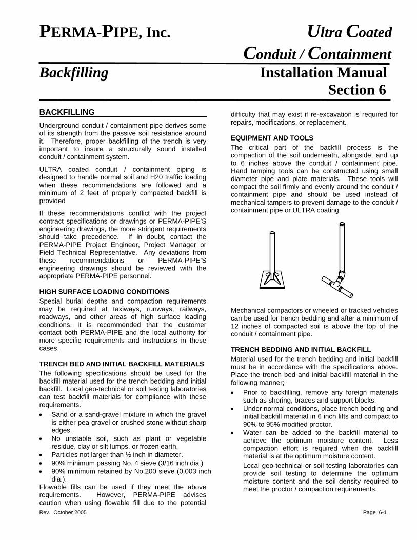
The critical part of the backfill process is the compaction of the soil underneath, alongside, and up to 6 inches above the conduit / containment pipe. Hand tamping tools can be constructed using small diameter pipe and plate materials. These tools will compact the soil firmly and evenly around the conduit / containment pipe and should be used instead of mechanical tampers to prevent damage to the conduit / containment pipe or ULTRA coating.
Mechanical compactors or wheeled or tracked vehicles can be used for trench bedding and after a minimum of 12 inches of compacted soil is above the top of the conduit / containment pipe. TRENCH BEDDING AND INITIAL BACKFILL
Material used for the trench bedding and initial backfill must be in accordance with the specifications above. Place the trench bed and initial backfill material in the following manner;
• Prior to backfilling, remove any foreign materials such as shoring, braces and support blocks.
• Under normal conditions, place trench bedding and initial backfill material in 6 inch lifts and compact to 90% to 95% modified proctor.
• Water can be added to the backfill material to achieve the optimum moisture content. Less compaction effort is required when the backfill material is at the optimum moisture content.
Local geo-technical or soil testing laboratories can provide soil testing to determine the optimum moisture content and the soil density required to meet the proctor / compaction requirements.
Rev. October 2005 Page 6-1
PERMA-PIPE, Inc. Ultra Coated Conduit / Containment Backfilling (cont.) Installation Manual Section 6 TRENCH BEDDING AND INITIAL BACKFILL (continued)
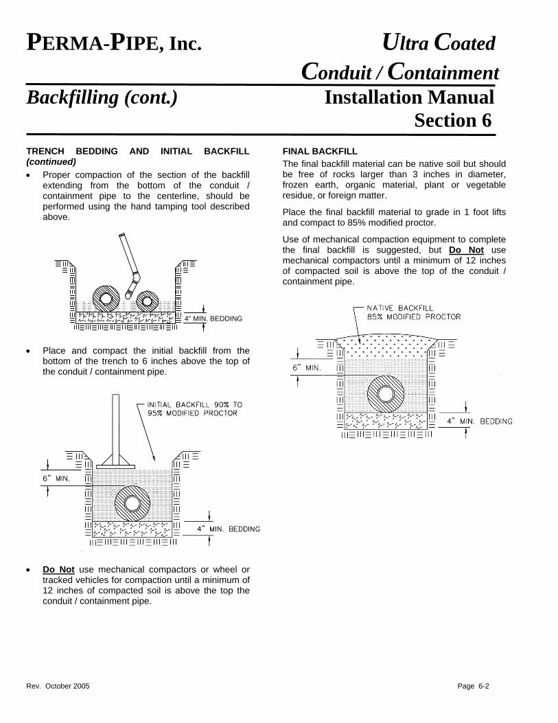
• Proper compaction of the section of the backfill extending from the bottom of the conduit / containment pipe to the centerline, should be performed using the hand tamping tool described above.
4" MIN. BEDDING
• Place and compact the initial backfill from the bottom of the trench to 6 inches above the top of the conduit / containment pipe.
• Do Not use mechanical compactors or wheel or tracked vehicles for compaction until a minimum of 12 inches of compacted soil is above the top the conduit / containment pipe.
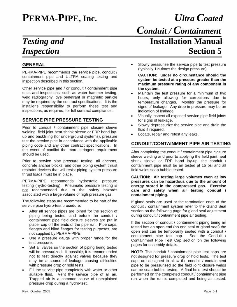
FINAL BACKFILL
The final backfill material can be native soil but should be free of rocks larger than 3 inches in diameter, frozen earth, organic material, plant or vegetable residue, or foreign matter.
Place the final backfill material to grade in 1 foot lifts and compact to 85% modified proctor.
Use of mechanical compaction equipment to complete the final backfill is suggested, but Do Not use mechanical compactors until a minimum of 12 inches of compacted soil is above the top of the conduit / containment pipe.
Rev. October 2005 Page 6-2
PERMA-PIPE, Inc. Ultra Coated Conduit / Containment
Testing and Installation Manual Inspection Section 5
GENERAL • Slowly pressurize the service pipe to test pressure
(typically 1½ times the design pressure).
PERMA-PIPE recommends the service pipe, conduit / containment pipe and ULTRA coating testing and inspection described in this section.
CAUTION: under no circumstance should the system be tested at a pressure greater than the maximum pressure rating of any component in the system.
Other service pipe and / or conduit / containment pipe tests and inspections, such as water hammer testing, weld radiography, dye penetrant or magnetic particle may be required by the contract specifications. It is the installer’s responsibility to perform these test and inspections, as required, for full contract compliance.
• Maintain the test pressure for a minimum of two hours, only allowing for corrections due to temperature changes. Monitor the pressure for signs of leakage. Any drop in pressure may be an indication of leakage.
• Visually inspect all exposed service pipe field joints for signs of leakage. SERVICE PIPE PRESSURE TESTING
• Slowly depressurize the service pipe and drain the fluid if required. Prior to conduit / containment pipe closure sleeve
welding, field joint heat shrink sleeve or FRP hand lay-up and backfilling (for underground systems), pressure test the service pipe in accordance with the applicable piping code and any other contract specifications. In the event of conflict the more stringent requirement should be used.
• Locate, repair and retest any leaks. CONDUIT/CONTAINMENT PIPE AIR TESTING After completing the conduit / containment pipe closure sleeve welding and prior to applying the field joint heat shrink sleeve or FRP hand lay-up, the conduit / containment pipe must be air tested at 15 psi and all field welds soap bubble tested.
Prior to service pipe pressure testing, all anchors, concrete anchor blocks, and other piping system thrust restraint devices that will resist piping system pressure thrust loads must be in place.
CAUTION: Air testing large volumes even at low pressures can be hazardous due to the amount of energy stored in the compressed gas. Exercise care and safety when air testing conduit / containment piping.
PERMA-PIPE recommends hydrostatic pressure testing (hydro-testing). Pneumatic pressure testing is not recommended due to the safety hazards associated with a large volume of high pressure gas. The following steps are recommended to be part of the service pipe hydro-test procedure;
If gland seals are used at the termination ends of the conduit / containment system refer to the Gland Seal section on the following page for gland seal adjustment during conduit / containment pipe air testing.
• After all service pipes are joined for the section of piping being tested, and before the conduit / containment pipe field closure sleeves are put in place, cap off the ends of the pipe run. Pipe caps, flanges and blind flanges for testing purposes, are not supplied by PERMA-PIPE.
If the section of conduit / containment piping being air tested has an open end (no end seal or gland seal) the open end can be temporarily sealed with a conduit / containment pipe test cap. See the Conduit / Containment Pipe Test Cap section on the following pages for assembly details.
• Use a pressure gauge with proper range for the test pressure.
• Set all valves so the section of piping being tested will be pressurized. If possible, it is recommended not to test directly against valves because they may be a source of leakage causing difficulties with pressure drop or hold tests.
• Fill the service pipe completely with water or other suitable fluid. Vent the service pipe of all air. Trapped air is a common cause of unexplained pressure drop during a hydro-test.
NOTE: The conduit / containment pipe test caps are not designed for pressure drop or hold tests. The test caps are designed to allow the conduit / containment pipe to be pressurized so the field joint closure welds can be soap bubble tested. A final hold test should be performed on the completed conduit / containment pipe run when the run is completed and being air tested.
Rev. October 2005 Page 5-1
PERMA-PIPE, Inc. Ultra Coated Conduit / Containment
Testing and Installation Manual Inspection (cont.) Section 5 CONDUIT/CONTAINMENT PIPE AIR TESTING (continued) The following steps are recommended to be part of the conduit / containment pipe air test procedure;
• Connect conduit / containment pipe test caps if required.
• Adjust gland seals if required. • Use a pressure gauge with proper range for the
test pressure. • Temporarily plug, cap or valve the conduit /
containment pipe vent and drain connections. • Slowly pressurize the conduit / containment pipe
with air to 15 psig.
CAUTION: The conduit / containment pipe is not designed for pressure above 15 psig unless specially designed for high pressure (greater than 15 psig). Do not pressurize the conduit / containment pipe above 15 psig. Conduit / containment pipe pressure above 15 psig may result in a hazardous condition and damage to or failure of the conduit / containment pipe.
CAUTION: Do not stand in front of, in line with, or near conduit / containment pipe test caps when the conduit / containment pipe is pressurized.
• Soap bubble test all field conduit / containment pipe closure sleeve welds.
• Mark the locations of any leaks found. Slowly depressurize the conduit / containment pipe, repairs all leaks and repeat the soap bubble test before continuing.
• Maintain the test pressure for a minimum of two hours, only allowing for corrections due to temperature changes. Monitor the pressure for signs of leakage. Any drop in pressure may be an indication of leakage.
• Locate any leaks. • Slowly depressurize the conduit / containment
pipe. • Repair any leaks and retest. • Remove conduit / containment pipe test caps, if
used. • Readjust gland seals for operating conditions. • Remove the air test caps, plugs or valves from the
conduit / containment pipe vents and drains.
GLAND SEALS
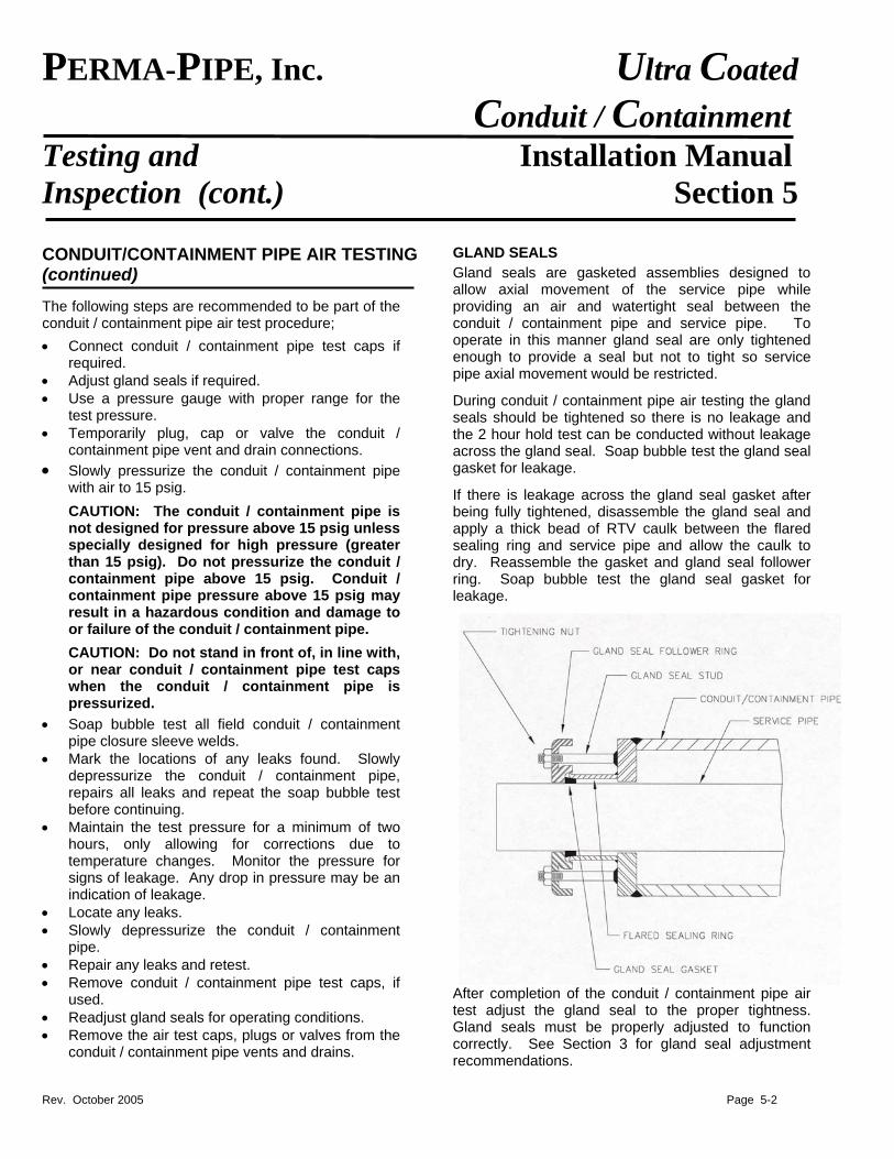
Gland seals are gasketed assemblies designed to allow axial movement of the service pipe while providing an air and watertight seal between the conduit / containment pipe and service pipe. To operate in this manner gland seal are only tightened enough to provide a seal but not to tight so service pipe axial movement would be restricted.
During conduit / containment pipe air testing the gland seals should be tightened so there is no leakage and the 2 hour hold test can be conducted without leakage across the gland seal. Soap bubble test the gland seal gasket for leakage.
If there is leakage across the gland seal gasket after being fully tightened, disassemble the gland seal and apply a thick bead of RTV caulk between the flared sealing ring and service pipe and allow the caulk to dry. Reassemble the gasket and gland seal follower ring. Soap bubble test the gland seal gasket for leakage.
After completion of the conduit / containment pipe air test adjust the gland seal to the proper tightness. Gland seals must be properly adjusted to function correctly. See Section 3 for gland seal adjustment recommendations.
Rev. October 2005 Page 5-2
PERMA-PIPE, Inc. Ultra Coated Conduit / Containment
Testing and Installation Manual Inspection (cont.) Section 5
CONDUIT / CONTAINMENT PIPE TEST CAPS
If the section of conduit / containment piping being air tested has an open end (no end seal or gland seal) the open end can be temporarily sealed with a conduit / containment pipe test cap.
NOTE: The conduit / containment pipe test caps are not designed for pressure drop or hold tests. The test caps are designed to allow the conduit / containment pipe to be pressurized so the field joint closure welds can be soap bubble tested. A final hold test should be performed on the completed conduit / containment pipe run when the run is completed and being air tested.
CAUTION: Pressure testing against a conduit / containment end cap generates large thrust loads on the test cap. Temporary bolting must be securely welded in place to resist this thrust load.
When using conduit / containment test caps observe the following precautions; • Do not pressurize the conduit / containment
test caps above 10 psig. • Full weld all bolting onto the conduit /
containment pipe to resist the test cap thrust load.
• Do not use conduit / containment test caps on conduit / containment pipe sizes larger than 36 inches.
Upon request, PERMA-PIPE can furnish test caps and rubber gaskets. The installer will furnish 5/8” diameter J-bolts or threaded rod, nuts and washers.
Temporarily install the test cap in the following manner;
• Tack weld the heads of the J-bolts to the uncoated edge of the conduit / containment pipe. Locate the J-bolts to match the bolt pattern of the test cap. Leave enough thread extending past the conduit / containment pipe for the test cap to be bolted on.
• Weld the J-bolts to the conduit / containment pipe using a minimum ¼ inch fillet weld all around the bolt diameter.
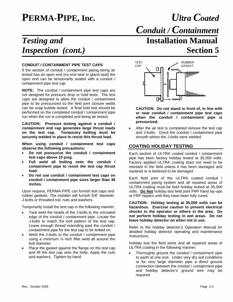
• Place the gasket against the flange on the test cap and lift the test cap onto the bolts. Apply the nuts and washers. Tighten by hand.
TESTCAP
RUBBER GASKET
CAUTION: Do not stand in front of, in line with or near conduit / containment pipe test caps when the conduit / containment pipe is pressurized.
• After the air test is completed remove the test cap and J-bolts. Grind the conduit / containment pipe smooth where the J-bolts were welded.
COATING HOLIDAY TESTING
Each section of ULTRA coated conduit / containment pipe has been factory holiday tested at 35,000 volts. Factory applied ULTRA coating does not need to be retested in the field unless it has been damaged and repaired or is believed to be damaged.
Each field joint of the ULTRA coated conduit / containment piping system and all repaired areas of ULTRA coating must be field holiday tested at 35,000 volts. Do Not holiday test field joint FRP hand lay-ups or FRP repairs until they have been fully cured.
CAUTION: Holiday testing at 35,000 volts can be hazardous. Exercise caution to prevent electrical shocks to the operator or others in the area. Do not perform holiday testing in wet areas. Do not leave holiday detector on when not in use.
Refer to the holiday detector’s Operation Manual for detailed holiday detector operating and maintenance instructions.
Holiday test the field joints and all repaired areas of ULTRA coating in the following manner;
• Thoroughly ground the conduit / containment pipe to earth at one end. Under very dry soil conditions or for very large diameter pipe a direct ground connection between the conduit / containment pipe and holiday detector’s ground wire may be required.
Rev. October 2005 Page 5-3
PERMA-PIPE, Inc. Ultra Coated Conduit / Containment
Testing and Installation Manual Inspection (cont.) Section 5 COATING HOLIDAY TESTING (continued)
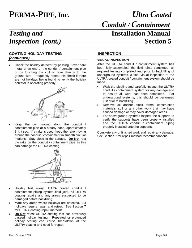
• Check the holiday detector by passing it over bare metal at an end of the conduit / containment pipe or by touching the coil or rake directly to the ground wire. Frequently repeat this check if there are not holidays being found to verify the holiday detector is operating properly.
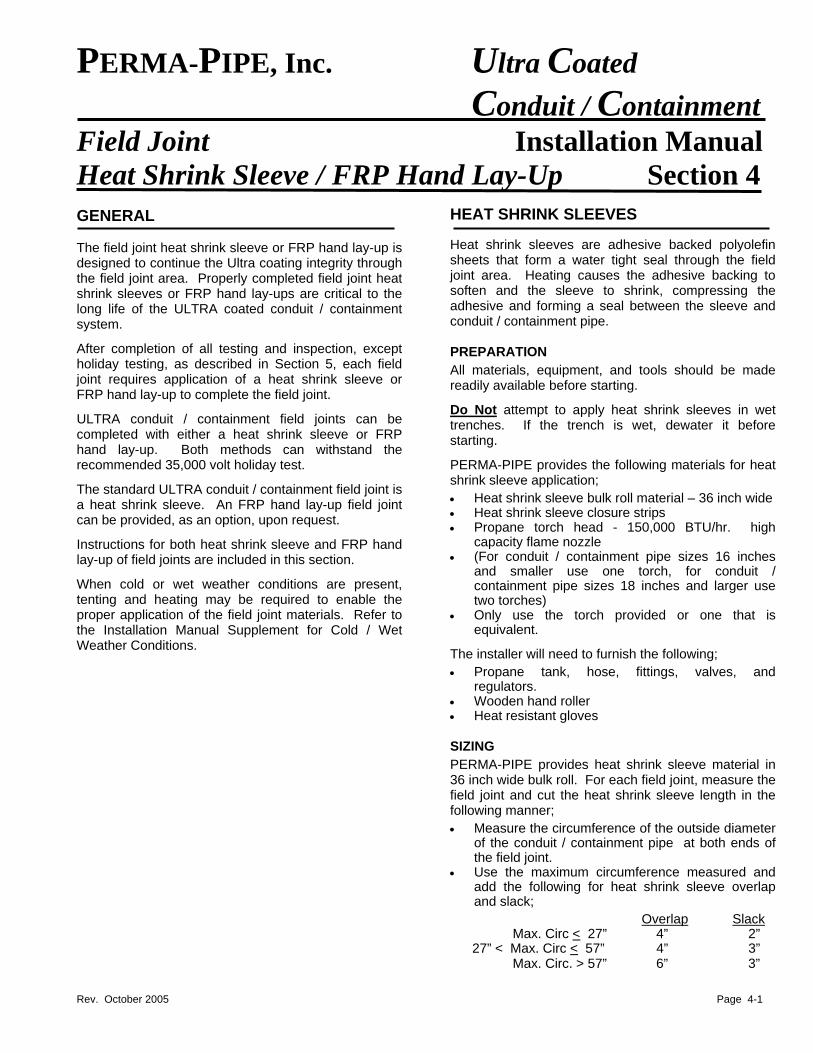
• Keep the coil moving along the conduit / containment pipe at a steady pace, approximately 1 ft. / sec. If a rake is used, keep the rake moving around the conduit / containment in smooth circular motions. Stay close to the surface. Do Not rest the rake on the conduit / containment pipe as this can damage the ULTRA coating.
• Holiday test every ULTRA coated conduit / containment piping system field joint, all ULTRA coating repairs and any areas suspected to be damaged before backfilling.
• Mark any areas where holidays are detected. All holidays require repair and retest. See Section 7 for ULTRA coating repair methods.
• Do Not retest ULTRA coating that has previously passed holiday testing. Repeated or prolonged holiday testing can cause breakdown of the ULTRA coating and need for repair.
INSPECTION
VISUAL INSPECTION
After the ULTRA conduit / containment system has been fully assembled, the field joints completed, all required testing completed and prior to backfilling of underground systems, a final visual inspection of the ULTRA coated conduit / containment system should be made.
• Walk the pipeline and carefully inspect the ULTRA conduit / containment system for any damage and to ensure all work has been completed. For underground systems, this should be performed just prior to backfilling.
• Remove all anchor block forms, construction materials, soil or any other work that may have caused damage or may cover damaged areas.
• For aboveground systems inspect the supports to verify the supports have been properly installed and the ULTRA conduit / containment piping properly installed onto the supports.
Complete any unfinished work and repair any damage. See Section 7 for repair method recommendations.
Rev. October 2005 Page 5-4
PERMA-PIPE, Inc. Ultra Coated Conduit / Containment
Field Joint Installation Manual Heat Shrink Sleeve / FRP Hand Lay-Up Section 4
HEAT SHRINK SLEEVES GENERAL Heat shrink sleeves are adhesive backed polyolefin sheets that form a water tight seal through the field joint area. Heating causes the adhesive backing to soften and the sleeve to shrink, compressing the adhesive and forming a seal between the sleeve and conduit / containment pipe.
The field joint heat shrink sleeve or FRP hand lay-up is designed to continue the Ultra coating integrity through the field joint area. Properly completed field joint heat shrink sleeves or FRP hand lay-ups are critical to the long life of the ULTRA coated conduit / containment system.
After completion of all testing and inspection, except holiday testing, as described in Section 5, each field joint requires application of a heat shrink sleeve or FRP hand lay-up to complete the field joint.
PREPARATION
All materials, equipment, and tools should be made readily available before starting.
Do Not attempt to apply heat shrink sleeves in wet trenches. If the trench is wet, dewater it before starting.
ULTRA conduit / containment field joints can be completed with either a heat shrink sleeve or FRP hand lay-up. Both methods can withstand the recommended 35,000 volt holiday test.
PERMA-PIPE provides the following materials for heat shrink sleeve application;
The standard ULTRA conduit / containment field joint is a heat shrink sleeve. An FRP hand lay-up field joint can be provided, as an option, upon request.
• Heat shrink sleeve bulk roll material – 36 inch wide • Heat shrink sleeve closure strips • Propane torch head - 150,000 BTU/hr. high
capacity flame nozzle
Instructions for both heat shrink sleeve and FRP hand lay-up of field joints are included in this section. • (For conduit / containment pipe sizes 16 inches
and smaller use one torch, for conduit / containment pipe sizes 18 inches and larger use two torches)
When cold or wet weather conditions are present, tenting and heating may be required to enable the proper application of the field joint materials. Refer to the Installation Manual Supplement for Cold / Wet Weather Conditions.
• Only use the torch provided or one that is equivalent.
The installer will need to furnish the following;
• Propane tank, hose, fittings, valves, and regulators.
• Wooden hand roller • Heat resistant gloves SIZING
PERMA-PIPE provides heat shrink sleeve material in 36 inch wide bulk roll. For each field joint, measure the field joint and cut the heat shrink sleeve length in the following manner;
• Measure the circumference of the outside diameter of the conduit / containment pipe at both ends of the field joint.
• Use the maximum circumference measured and add the following for heat shrink sleeve overlap and slack;
Overlap Slack Max. Circ < 27” 4” 2” 27” < Max. Circ < 57” 4” 3” Max. Circ. > 57” 6” 3”
Rev. October 2005 Page 4-1
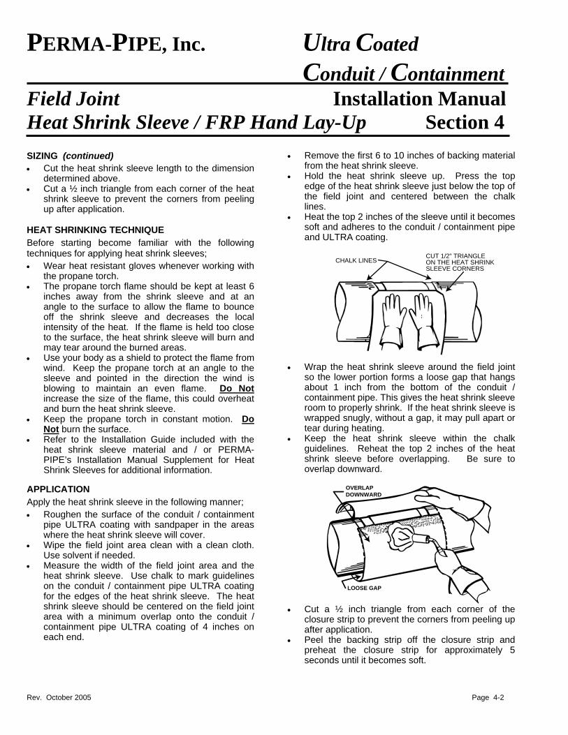
PERMA-PIPE, Inc. Ultra Coated Conduit / Containment
Field Joint Installation Manual Heat Shrink Sleeve / FRP Hand Lay-Up Section 4
SIZING (continued)
• Cut the heat shrink sleeve length to the dimension determined above.
• Cut a ½ inch triangle from each corner of the heat shrink sleeve to prevent the corners from peeling up after application.
HEAT SHRINKING TECHNIQUE
Before starting become familiar with the following techniques for applying heat shrink sleeves;
• Wear heat resistant gloves whenever working with the propane torch.
• The propane torch flame should be kept at least 6 inches away from the shrink sleeve and at an angle to the surface to allow the flame to bounce off the shrink sleeve and decreases the local intensity of the heat. If the flame is held too close to the surface, the heat shrink sleeve will burn and may tear around the burned areas.
• Use your body as a shield to protect the flame from wind. Keep the propane torch at an angle to the sleeve and pointed in the direction the wind is blowing to maintain an even flame. Do Not increase the size of the flame, this could overheat and burn the heat shrink sleeve.
• Keep the propane torch in constant motion. Do Not burn the surface.
• Refer to the Installation Guide included with the heat shrink sleeve material and / or PERMA-PIPE’s Installation Manual Supplement for Heat Shrink Sleeves for additional information.
APPLICATION
Apply the heat shrink sleeve in the following manner;
• Roughen the surface of the conduit / containment pipe ULTRA coating with sandpaper in the areas where the heat shrink sleeve will cover.
• Wipe the field joint area clean with a clean cloth. Use solvent if needed.
• Measure the width of the field joint area and the heat shrink sleeve. Use chalk to mark guidelines on the conduit / containment pipe ULTRA coating for the edges of the heat shrink sleeve. The heat shrink sleeve should be centered on the field joint area with a minimum overlap onto the conduit / containment pipe ULTRA coating of 4 inches on each end.
• Remove the first 6 to 10 inches of backing material from the heat shrink sleeve.
• Hold the heat shrink sleeve up. Press the top edge of the heat shrink sleeve just below the top of the field joint and centered between the chalk lines.
• Heat the top 2 inches of the sleeve until it becomes soft and adheres to the conduit / containment pipe and ULTRA coating.
CHALK LINESCUT 1/2" TRIANGLEON THE HEAT SHRINKSLEEVE CORNERS
• Wrap the heat shrink sleeve around the field joint so the lower portion forms a loose gap that hangs about 1 inch from the bottom of the conduit / containment pipe. This gives the heat shrink sleeve room to properly shrink. If the heat shrink sleeve is wrapped snugly, without a gap, it may pull apart or tear during heating.
• Keep the heat shrink sleeve within the chalk guidelines. Reheat the top 2 inches of the heat shrink sleeve before overlapping. Be sure to overlap downward.
LOOSE GAP
OVERLAPDOWNWARD
• Cut a ½ inch triangle from each corner of the
closure strip to prevent the corners from peeling up after application.
• Peel the backing strip off the closure strip and preheat the closure strip for approximately 5 seconds until it becomes soft.
Rev. October 2005 Page 4-2
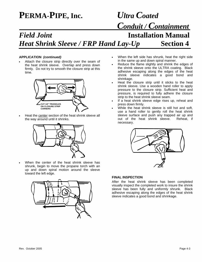
PERMA-PIPE, Inc. Ultra Coated Conduit / Containment
Field Joint Installation Manual Heat Shrink Sleeve / FRP Hand Lay-Up Section 4 APPLICATION (continued)
• Attach the closure strip directly over the seam of the heat shrink sleeve. Overlap and press down firmly. Do not try to smooth the closure strip at this time.
CUT 1/2" TRIANGLESON CLOSURE STRIPCORNERS
• Heat the center section of the heat shrink sleeve all the way around until it shrinks.
• When the center of the heat shrink sleeve has shrunk, begin to move the propane torch with an up and down spiral motion around the sleeve toward the left edge.
• When the left side has shrunk, heat the right side in the same up and down spiral manner.
• Reduce the flame slightly and shrink the edges of the shrink sleeve onto the ULTRA coating. Black adhesive escaping along the edges of the heat shrink sleeve indicates a good bond and shrinkage.
• Heat the closure strip until it sticks to the heat shrink sleeve. Use a wooden hand roller to apply pressure to the closure strip. Sufficient heat and pressure, is required to fully adhere the closure strip to the heat shrink sleeve seam.
• If a heat shrink sleeve edge rises up, reheat and press down firmly.
• While the heat shrink sleeve is still hot and soft, use a hand roller to gently roll the heat shrink sleeve surface and push any trapped air up and out of the heat shrink sleeve. Reheat, if necessary.
FINAL INSPECTION
After the heat shrink sleeve has been completed visually inspect the completed work to insure the shrink sleeve has been fully and uniformly shrunk. Black adhesive escaping along the edges of the heat shrink sleeve indicates a good bond and shrinkage.
Rev. October 2005 Page 4-3
PERMA-PIPE, Inc. Ultra Coated Conduit / Containment
Field Joint Installation Manual Heat Shrink Sleeve / FRP Hand Lay-Up Section 4
FRP HAND LAY-UP FRP hand lay-up field joints consist of two wraps of fiberglass bi-ply cloth, fully saturated with polyester resin to achieve a minimum thickness of 100 mils. A properly completed FRP hand lay-up will pass a 35,000 volt holiday test. See Section 5 for holiday test requirements.
The FRP application temperature range must be between 60°F to 100°F. Contact PERMA-PIPE for special procedures if the application temperature is outside this temperature range. MATERIALS
All materials, equipment and tools should be readily available before starting.
PERMA-PIPE provides the following FRP hand lay-up materials:
• Fiberglass Bi-Ply Mat • Un-Promoted Polyester Resin • Catalyst Promoter, Dimethylaniline (DMA) • Catalyst, powdered organic peroxide (BFF-50) • Metal Finned Roller • Promoter Dispenser
The installer must furnish the following materials:
• Grinder and Grinding Wheel • Disposable Mixing Pails (1 or 3 Gallon) • Variable speed drill for mixing • Acetone (or equivalent solvent) • Heavy-Duty Rubber Gloves • Wooden Mixing Paddles • Wire Brush • Dry Rags • Plastic Drop Cloths (4 mils thick) • Sheets of Plywood (48 inch wide)
WORKING AND SAFETY CONSIDERATIONS
• Refer to the Material Safety Data Sheets (MSDS Sheets) for proper handling, storage and use. Some materials may be flammable or hazardous. Extreme care must be taken so they are stored away from heat, sparks and open flames.
• Contact PERMA-PIPE if additional MSDS Sheets are needed.
• Keep the materials in their original shipping containers. The recommended storage temperature range for the FRP chemicals is 60°F to 85° F.
• Do Not store the chemicals out of the recommended temperature range or allow the chemicals to freeze as this may hinder their effectiveness or render them useless.
• Avoid skin and eye contact. Wear safety gloves and safety glasses. Wash with soap and water after skin contact. Flush with water for 15 minutes and medical attention for eye contact.
• When working in a trench or with other nearby structures, make certain there is sufficient space to be able to see and roll the bottom and sides of the FRP hand lay-up.
• Place the metal finned rollers and any other resin covered tools or rubber gloves in a pail of acetone after each field joint has been wrapped, and before the resin is cured. Because acetone evaporates rapidly, use a pail with a lid.
• Clean all resin and fiberglass fibers from between the fins on the rollers. Trying to roll the air out from under the fiberglass bi-ply mat is very difficult without a clean metal finned roller.
• Always be sure that the metal finned rollers, tools and gloves are completely dry before using on a new area.
• Always work in a dry environment. Keep the area dry until the resin has cured.
• If for some reason the FRP hand lay-up is put on incorrectly, carefully peel it off and re-wrap it while still wet.
Rev. October 2005 Page 4-4
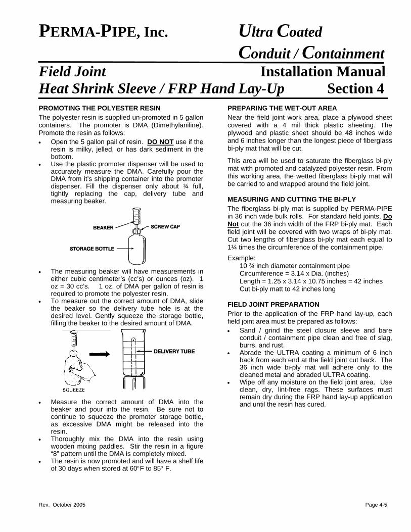
PERMA-PIPE, Inc. Ultra Coated Conduit / Containment
Field Joint Installation Manual Heat Shrink Sleeve / FRP Hand Lay-Up Section 4 PROMOTING THE POLYESTER RESIN
The polyester resin is supplied un-promoted in 5 gallon containers. The promoter is DMA (Dimethylaniline). Promote the resin as follows:
• Open the 5 gallon pail of resin. DO NOT use if the resin is milky, jelled, or has dark sediment in the bottom.
• Use the plastic promoter dispenser will be used to accurately measure the DMA. Carefully pour the DMA from it’s shipping container into the promoter dispenser. Fill the dispenser only about ¾ full, tightly replacing the cap, delivery tube and measuring beaker.
• The measuring beaker will have measurements in
either cubic centimeter’s (cc’s) or ounces (oz). 1 oz = 30 cc’s. 1 oz. of DMA per gallon of resin is required to promote the polyester resin.
• To measure out the correct amount of DMA, slide the beaker so the delivery tube hole is at the desired level. Gently squeeze the storage bottle, filling the beaker to the desired amount of DMA.
• Measure the correct amount of DMA into the
beaker and pour into the resin. Be sure not to continue to squeeze the promoter storage bottle, as excessive DMA might be released into the resin.
• Thoroughly mix the DMA into the resin using wooden mixing paddles. Stir the resin in a figure “8” pattern until the DMA is completely mixed.
• The resin is now promoted and will have a shelf life of 30 days when stored at 60°F to 85° F.
PREPARING THE WET-OUT AREA
Near the field joint work area, place a plywood sheet covered with a 4 mil thick plastic sheeting. The plywood and plastic sheet should be 48 inches wide and 6 inches longer than the longest piece of fiberglass bi-ply mat that will be cut.
This area will be used to saturate the fiberglass bi-ply mat with promoted and catalyzed polyester resin. From this working area, the wetted fiberglass bi-ply mat will be carried to and wrapped around the field joint. MEASURING AND CUTTING THE BI-PLY
The fiberglass bi-ply mat is supplied by PERMA-PIPE in 36 inch wide bulk rolls. For standard field joints, Do Not cut the 36 inch width of the FRP bi-ply mat. Each field joint will be covered with two wraps of bi-ply mat. Cut two lengths of fiberglass bi-ply mat each equal to 1¼ times the circumference of the containment pipe.
Example: 10 ¾ inch diameter containment pipe Circumference = 3.14 x Dia. (inches) Length = 1.25 x 3.14 x 10.75 inches = 42 inches
Cut bi-ply matt to 42 inches long
FIELD JOINT PREPARATION
Prior to the application of the FRP hand lay-up, each field joint area must be prepared as follows:
• Sand / grind the steel closure sleeve and bare conduit / containment pipe clean and free of slag, burrs, and rust.
• Abrade the ULTRA coating a minimum of 6 inch back from each end at the field joint cut back. The 36 inch wide bi-ply mat will adhere only to the cleaned metal and abraded ULTRA coating.
• Wipe off any moisture on the field joint area. Use clean, dry, lint-free rags. These surfaces must remain dry during the FRP hand lay-up application and until the resin has cured.
Rev. October 2005 Page 4-5
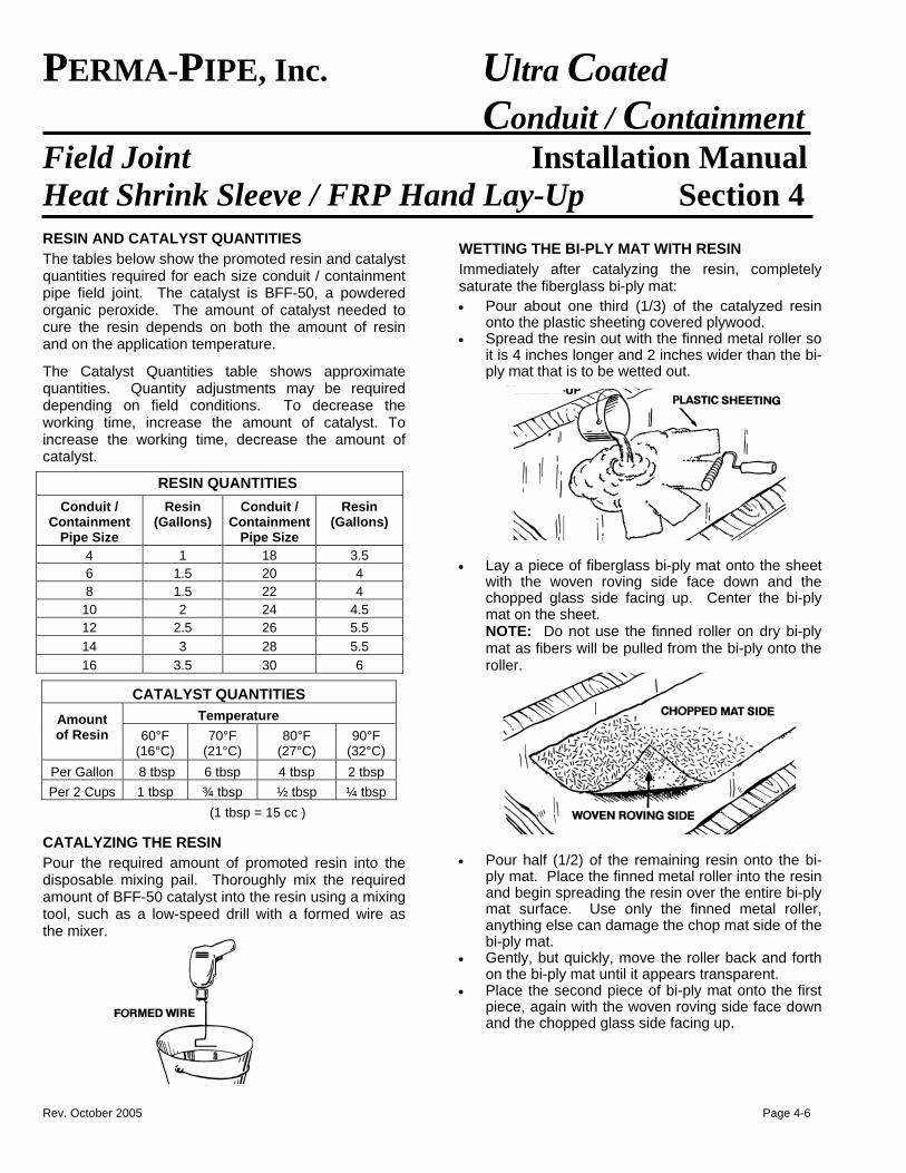
PERMA-PIPE, Inc. Ultra Coated Conduit / Containment
Field Joint Installation Manual Heat Shrink Sleeve / FRP Hand Lay-Up Section 4 RESIN AND CATALYST QUANTITIES
The tables below show the promoted resin and catalyst quantities required for each size conduit / containment pipe field joint. The catalyst is BFF-50, a powdered organic peroxide. The amount of catalyst needed to cure the resin depends on both the amount of resin and on the application temperature.
The Catalyst Quantities table shows approximate quantities. Quantity adjustments may be required depending on field conditions. To decrease the working time, increase the amount of catalyst. To increase the working time, decrease the amount of catalyst.
RESIN QUANTITIES
Conduit / Containment
Pipe Size
Resin (Gallons)
Conduit / Containment
Pipe Size
Resin (Gallons)
4 1 18 3.5 6 1.5 20 4 8 1.5 22 4
10 2 24 4.5 12 2.5 26 5.5 14 3 28 5.5 16 3.5 30 6
CATALYST QUANTITIES Temperature Amount
of Resin
60°F (16°C)
70°F (21°C)
80°F (27°C)
90°F (32°C)
Per Gallon 8 tbsp 6 tbsp 4 tbsp 2 tbsp Per 2 Cups 1 tbsp ¾ tbsp ½ tbsp ¼ tbsp
(1 tbsp = 15 cc ) CATALYZING THE RESIN
Pour the required amount of promoted resin into the disposable mixing pail. Thoroughly mix the required amount of BFF-50 catalyst into the resin using a mixing tool, such as a low-speed drill with a formed wire as the mixer.
WETTING THE BI-PLY MAT WITH RESIN
Immediately after catalyzing the resin, completely saturate the fiberglass bi-ply mat:
• Pour about one third (1/3) of the catalyzed resin onto the plastic sheeting covered plywood.
• Spread the resin out with the finned metal roller so it is 4 inches longer and 2 inches wider than the bi-ply mat that is to be wetted out.
• Lay a piece of fiberglass bi-ply mat onto the sheet
with the woven roving side face down and the chopped glass side facing up. Center the bi-ply mat on the sheet. NOTE: Do not use the finned roller on dry bi-ply mat as fibers will be pulled from the bi-ply onto the roller.
• Pour half (1/2) of the remaining resin onto the bi-
ply mat. Place the finned metal roller into the resin and begin spreading the resin over the entire bi-ply mat surface. Use only the finned metal roller, anything else can damage the chop mat side of the bi-ply mat.
• Gently, but quickly, move the roller back and forth on the bi-ply mat until it appears transparent.
• Place the second piece of bi-ply mat onto the first piece, again with the woven roving side face down and the chopped glass side facing up.
Rev. October 2005 Page 4-6
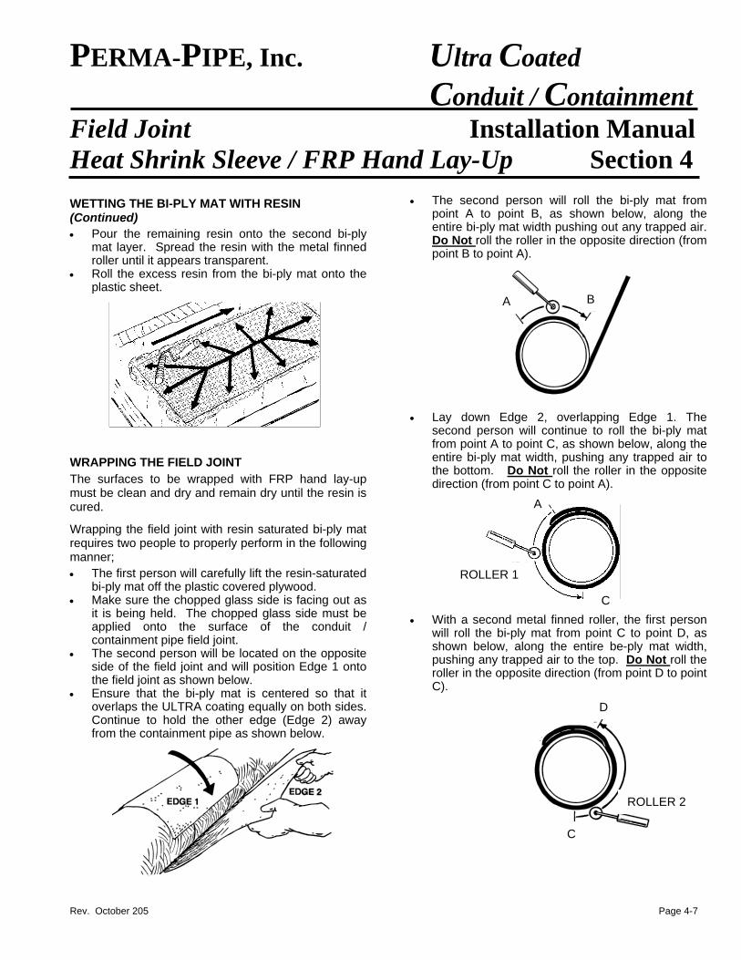
PERMA-PIPE, Inc. Ultra Coated Conduit / Containment
Field Joint Installation Manual Heat Shrink Sleeve / FRP Hand Lay-Up Section 4
WETTING THE BI-PLY MAT WITH RESIN (Continued)
• Pour the remaining resin onto the second bi-ply mat layer. Spread the resin with the metal finned roller until it appears transparent.
• Roll the excess resin from the bi-ply mat onto the plastic sheet.
WRAPPING THE FIELD JOINT
The surfaces to be wrapped with FRP hand lay-up must be clean and dry and remain dry until the resin is cured.
Wrapping the field joint with resin saturated bi-ply mat requires two people to properly perform in the following manner;
• The first person will carefully lift the resin-saturated bi-ply mat off the plastic covered plywood.
• Make sure the chopped glass side is facing out as it is being held. The chopped glass side must be applied onto the surface of the conduit / containment pipe field joint.
• The second person will be located on the opposite side of the field joint and will position Edge 1 onto the field joint as shown below.
• Ensure that the bi-ply mat is centered so that it overlaps the ULTRA coating equally on both sides. Continue to hold the other edge (Edge 2) away from the containment pipe as shown below.
• The second person will roll the bi-ply mat from point A to point B, as shown below, along the entire bi-ply mat width pushing out any trapped air. Do Not roll the roller in the opposite direction (from point B to point A).
• Lay down Edge 2, overlapping Edge 1. The
second person will continue to roll the bi-ply mat from point A to point C, as shown below, along the entire bi-ply mat width, pushing any trapped air to the bottom. Do Not roll the roller in the opposite direction (from point C to point A).
B A
A
ROLLER 1
• With a second metal finned roller, the first person
will roll the bi-ply mat from point C to point D, as shown below, along the entire be-ply mat width, pushing any trapped air to the top. Do Not roll the roller in the opposite direction (from point D to point C).
C
D
ROLLER 2
C
Rev. October 205 Page 4-7
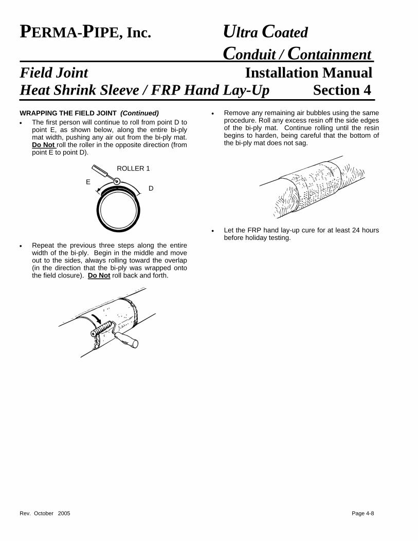
PERMA-PIPE, Inc. Ultra Coated Conduit / Containment
Field Joint Installation Manual Heat Shrink Sleeve / FRP Hand Lay-Up Section 4
WRAPPING THE FIELD JOINT (Continued)
• The first person will continue to roll from point D to point E, as shown below, along the entire bi-ply mat width, pushing any air out from the bi-ply mat. Do Not roll the roller in the opposite direction (from point E to point D).
• Repeat the previous three steps along the entire
width of the bi-ply. Begin in the middle and move out to the sides, always rolling toward the overlap (in the direction that the bi-ply was wrapped onto the field closure). Do Not roll back and forth.
• Remove any remaining air bubbles using the same procedure. Roll any excess resin off the side edges of the bi-ply mat. Continue rolling until the resin begins to harden, being careful that the bottom of the bi-ply mat does not sag.
• Let the FRP hand lay-up cure for at least 24 hours
before holiday testing.
ROLLER 1
E D
Rev. October 2005 Page 4-8
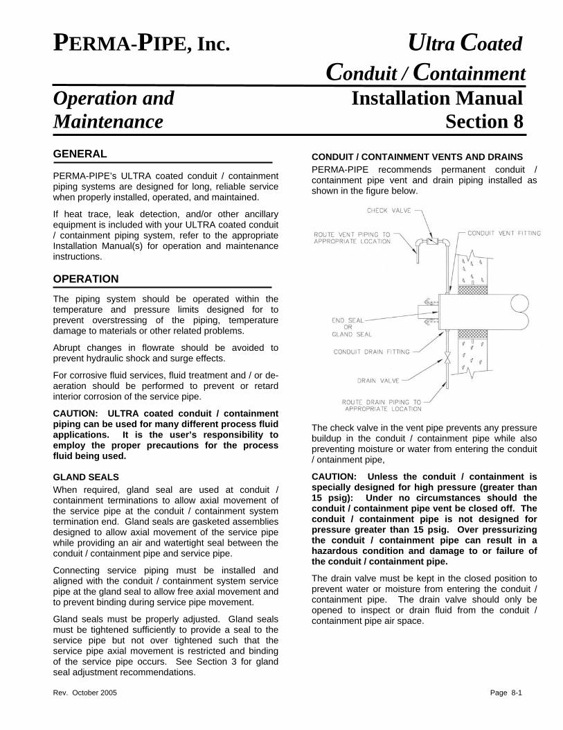
PERMA-PIPE, Inc. Ultra Coated Conduit / Containment Operation and Installation Manual Maintenance Section 8
GENERAL PERMA-PIPE’s ULTRA coated conduit / containment piping systems are designed for long, reliable service when properly installed, operated, and maintained.
If heat trace, leak detection, and/or other ancillary equipment is included with your ULTRA coated conduit / containment piping system, refer to the appropriate Installation Manual(s) for operation and maintenance instructions. OPERATION The piping system should be operated within the temperature and pressure limits designed for to prevent overstressing of the piping, temperature damage to materials or other related problems.
Abrupt changes in flowrate should be avoided to prevent hydraulic shock and surge effects.
For corrosive fluid services, fluid treatment and / or de-aeration should be performed to prevent or retard interior corrosion of the service pipe.
CAUTION: ULTRA coated conduit / containment piping can be used for many different process fluid applications. It is the user’s responsibility to employ the proper precautions for the process fluid being used. GLAND SEALS
When required, gland seal are used at conduit / containment terminations to allow axial movement of the service pipe at the conduit / containment system termination end. Gland seals are gasketed assemblies designed to allow axial movement of the service pipe while providing an air and watertight seal between the conduit / containment pipe and service pipe.
Connecting service piping must be installed and aligned with the conduit / containment system service pipe at the gland seal to allow free axial movement and to prevent binding during service pipe movement.
Gland seals must be properly adjusted. Gland seals must be tightened sufficiently to provide a seal to the service pipe but not over tightened such that the service pipe axial movement is restricted and binding of the service pipe occurs. See Section 3 for gland seal adjustment recommendations.
CONDUIT / CONTAINMENT VENTS AND DRAINS
PERMA-PIPE recommends permanent conduit / containment pipe vent and drain piping installed as
wn in the figure below. sho
The check valve in the vent pipe prevents any pressure buildup in the conduit / containment pipe while also preventing moisture or water from entering the conduit / ontainment pipe,
CAUTION: Unless the conduit / containment is specially designed for high pressure (greater than 15 psig): Under no circumstances should the conduit / containment pipe vent be closed off. The conduit / containment pipe is not designed for pressure greater than 15 psig. Over pressurizing the conduit / containment pipe can result in a hazardous condition and damage to or failure of the conduit / containment pipe.
The drain valve must be kept in the closed position to prevent water or moisture from entering the conduit / containment pipe. The drain valve should only be opened to inspect or drain fluid from the conduit / containment pipe air space.
Rev. October 2005 Page 8-1
PERMA-PIPE, Inc. Ultra Coated Conduit / Containment Operation and Installation Manual Maintenance (cont’d) Section 8
MAINTENANCE MAINTENANCE
Periodic maintenance should be performed to ensure the ULTRA coated conduit / containment piping system is operating properly, is in good condition and to maximize its service life. Any signs of damage, degradation, or deterioration should be identified, evaluated, and repaired.
Periodic maintenance should be performed to ensure the ULTRA coated conduit / containment piping system is operating properly, is in good condition and to maximize its service life. Any signs of damage, degradation, or deterioration should be identified, evaluated, and repaired.
It is critical that the ULTRA coated conduit / containment pipe’s coating and leak tight integrity is maintained and the conduit / containment piping airspace is kept dry to prevent degradation or corrosion to the conduit / containment and / or service pipe(s) that could severely reduce the life of the ULTRA coated conduit / containment piping system.
It is critical that the ULTRA coated conduit / containment pipe’s coating and leak tight integrity is maintained and the conduit / containment piping airspace is kept dry to prevent degradation or corrosion to the conduit / containment and / or service pipe(s) that could severely reduce the life of the ULTRA coated conduit / containment piping system.
At least twice a year the ULTRA coated conduit / containment piping system should be inspected so any problems that may arise can be detected early. The actual frequency of inspection should be adjusted to account for service and operating conditions, environment, climate, and / or ground conditions.
At least twice a year the ULTRA coated conduit / containment piping system should be inspected so any problems that may arise can be detected early. The actual frequency of inspection should be adjusted to account for service and operating conditions, environment, climate, and / or ground conditions.
PERMA-PIPE INSPECTION SERVICES can provide infrared leak detection and energy evaluation surveys, sonic leak detection, ultrasonic pipe wall thickness testing and evaluation, and tracer gas leak detection services. These services can be useful for inspecting and maintaining your piping system. Contact PERMA-PIPE for additional information.
PERMA-PIPE INSPECTION SERVICES can provide infrared leak detection and energy evaluation surveys, sonic leak detection, ultrasonic pipe wall thickness testing and evaluation, and tracer gas leak detection services. These services can be useful for inspecting and maintaining your piping system. Contact PERMA-PIPE for additional information.
An inspection and maintenance log should be set up with all inspections and maintenance recorded. The inspection and maintenance log can be helpful for identify trends, providing documentation of inspection and maintenance activities, and troubleshooting.
An inspection and maintenance log should be set up with all inspections and maintenance recorded. The inspection and maintenance log can be helpful for identify trends, providing documentation of inspection and maintenance activities, and troubleshooting.
Perform the maintenance listed below. Any signs of damage, degradation, or deterioration should be identified, evaluated, and repaired.
Perform the maintenance listed below. Any signs of damage, degradation, or deterioration should be identified, evaluated, and repaired.
GENERAL MAINTENANCE GENERAL MAINTENANCE • Inspect all conduit / containment system termination
ends, building entries, manhole entries, and valve pits. Under no circumstances should water be allowed to cover the termination ends. Accumulating water should be removed immediately.
• Inspect all conduit / containment system termination ends, building entries, manhole entries, and valve pits. Under no circumstances should water be allowed to cover the termination ends. Accumulating water should be removed immediately.
• Inspect gland seals for signs of gasket wear or leakage and binding of the service pipe. Inspect the surface of the service pipe passing through gland seals for any nicks, scratches, gouges or corrosion that would affect the gasket seal.
• Inspect gland seals for signs of gasket wear or leakage and binding of the service pipe. Inspect the surface of the service pipe passing through gland seals for any nicks, scratches, gouges or corrosion that would affect the gasket seal.
• If required, adjust the tightness of the gland seal
tight enough to seal but do not over tighten. • If required, adjust the tightness of the gland seal
tight enough to seal but do not over tighten. • Carefully open the conduit / containment pipe drain
valve and inspect for any fluid accumulation. Remove any accumulated fluid immediately and determine its source and cause.
• Carefully open the conduit / containment pipe drain valve and inspect for any fluid accumulation. Remove any accumulated fluid immediately and determine its source and cause. CAUTION: ULTRA coated conduit / containment pipe can be used for many different process fluid applications. It is the user’s responsibility to employ the proper precautions for the process fluid being used.
CAUTION: ULTRA coated conduit / containment pipe can be used for many different process fluid applications. It is the user’s responsibility to employ the proper precautions for the process fluid being used.
• Dry out all conduit / containment pipe that has been wet to prevent corrosion of the service and conduit / containment pipes from continuing or occurring. Contact PERMA-PIPE for recommended conduit / containment pipe dry out procedures.
• Dry out all conduit / containment pipe that has been wet to prevent corrosion of the service and conduit / containment pipes from continuing or occurring. Contact PERMA-PIPE for recommended conduit / containment pipe dry out procedures.
• Air test the conduit / containment pipe to verify it is leak tight. If the service pipe is at an elevated temperature be careful to consider any increase in pressure of the air in the conduit / containment pipe airspace that may occur due to being heated. Do
• Air test the conduit / containment pipe to verify it is leak tight. If the service pipe is at an elevated temperature be careful to consider any increase in pressure of the air in the conduit / containment pipe airspace that may occur due to being heated. Do Not over pressurize the conduit / containment pipe.
• Verify the conduit / containment pipe vent check valves are operational and will properly vent any pressure build up in the conduit / containment pipe.
• Verify water or other fluid treatment and de-aeration procedures are being properly performed to prevent internal corrosion of the service pipe.
• Inspect all ancillary equipment – valves, expansion joints, pipe supports, pipe anchors, steam traps, flash tanks, etc. Perform all necessary repairs, replacement and maintenance.
BELOWGROUND SYSTEMS • On all wall and floor entries, inspect the link seals,
packings, or other sealing devices being used to assure proper sealing of ground water.
• Inspect for signs of other excavations or constructions that could interfere with the buried conduit / containment system.
• Inspect the landscape for signs of fluid leakage or excessive heat loss or gain. Grass browning or snow melting above the conduit / containment system are signs of excessive heat loss or gain.
ABOVEGROUND SYSTEMS • Inspect all exposed piping. • Inspect the ULTRA coating for signs of wear,
weathering or damage. Inspect closely at support locations for signs of wear or damage.
• Inspect the condition of all field joint closures. Rev. October 2005 Page 8-2
PERMA-PIPE, Inc. Ultra Coated Conduit / Containment
Installation Manual
A Subsidiary of MFRI, Inc. 7720 North Lehigh AvenueNiles, Illinois 60714-3491 Phone (847) 966-2235 Fax (847) 470-1204 www.permapipe.com
Rev. October 2005
WARRANTY Seller warrants to the original Buyer only that the products sold hereunder will substantially comply with the above referenced technical specifications for the products and that no product will have any defect in Seller’s design, workmanship or material. Seller shall not be responsible for and does not warrant the installation of the products. Seller agrees to provide field services as provided herein and warrants only that the information provided to Seller during such field service visits will be consistent with Seller’s recommendations for installation. Seller specifically rejects all other warranties in the contract documents for the project, which may apply to Seller’s products. The foregoing warranty shall be in effect with respect to each product sold hereunder only for a period of fifteen (15) months from the date of completion of testing of such product, but in no event more than eighteen (18) months from the date of shipment by Seller of such product; provided, however, no claim shall be permitted under the warranties contained herein unless Buyer shall give to Seller written notice of all respects in which Buyer claims the product to be defective or at a variance with specifications within ten (10) days from the date Buyer discovers or should have discovered a defect or variance from specifications, but in no event later than eighteen (18) months after shipment of such product, and unless Buyer shall afford Seller a reasonable opportunity to inspect such product after notice has been given. The foregoing warranties shall not apply to any products or components thereof, which have been subject to abnormal or improper use, negligence or accident or which have been altered or repaired by someone other than Seller or Seller’s authorized representative. No product shall be returned without Seller’s prior written consent. Buyer shall accept minor variations in dimensions or other variance from specifications provided that there is no impairment of function or useful life of the product. Seller warrants that its title to the product sold hereunder is good, and that the transfer thereof to Buyer is rightful. Seller’s obligations under the warranties contained herein and any other provision of the Agreement determined to constitute a warranty by the Seller of the products to be sold pursuant hereto, and Buyer’s remedies for any defective or non-conforming products shall be limited solely to the repair or replacement, as elected by Seller of defective or non-conforming materials. To the maximum extent permitted by law, Buyer irrevocably waives all claims against Seller for money damages relating to the condition, use and performance of the goods sold pursuant hereto, including claims based upon tort, strict liability, negligence and product liability. Notwithstanding the provisions of the preceding sentence, if money damages are assessed against the Seller, in no event shall Seller’s liability for such damages exceed the purchase price of products sold by Seller. IN NO EVENT, WHETHER BECAUSE OF A BREACH OF WARRANTY OR REPRESENTATION OR ANY OTHER CAUSE, WHETHER BASED UPON CONTRACT, TORT, WARRANTY OR OTHERWISE, ARISING OUT OF PERFORMANCE OR NON-PERFORMANCE BY SELLER OF IT’S OBLIGATIONS UNDER THIS AGREEMENT OR WITH RESPECT TO THE PRODUCTS SOLD PURSUANT HERETO SHALL SELLER BE LIABLE FOR LOST EARNINGS, INCOME OR PROFITS OR INDIRECT, INCIDENTAL OR CONSEQUENTIAL DAMAGES. THE IMPLIED WARRANTIES OF MERCHANTABILITY AND FITNESS FOR A PARTICULAR PURPOSE AND, EXCEPT AS SPECIFICALLY SET FORTH HEREIN, ALL OTHER WARRANTIES AND REPRESENTATIONS, EXPRESS OR IMPLIED, ARE HEREBY DISCLAIMED AND EXCLUDED. NOTHING SHALL BE CONSTRUED AS AN ADDITIONAL WARRANTY UNLESS SPECIFICALLY DESIGNATED AS SUCH IN WRITING AND SIGNED BY THE SELLER, IN WHICH CASE SUCH ADDITIONAL WARRANTY SHALL BE SUBJECT TO THE PROVISIONS HERIN AS TO THE DURATION AND LIMITATION OF REMEDY UNLESS SUCH ADDITIONAL WARRANTY EXPRESSLY VARIES SUCH PROVISIONS.