Embed Size (px)
Citation preview
UserManual
• Installation• Operation• Programming
Electro Industries/GaugeTech1800 Shames Drive•Westbury, New York 11590
Tel 516.334.0870•Fax 516.338.4741• www.electroind.com
Universal Communication Converter
UNICOM 2500UNICOM 2500
UNICOM 2500
UNICOM-2500
UNIVERSAL COMMUNICATION COVERTER
1800 Shames DriveWestbury, New York 11590
Tel: (516) 334-0870 Fax: (516) 338-4741
USER'S INSTALLATION & OPERATION MANUALVersion 1.3/ 11-2014
U N I C O M 2 5 0 0
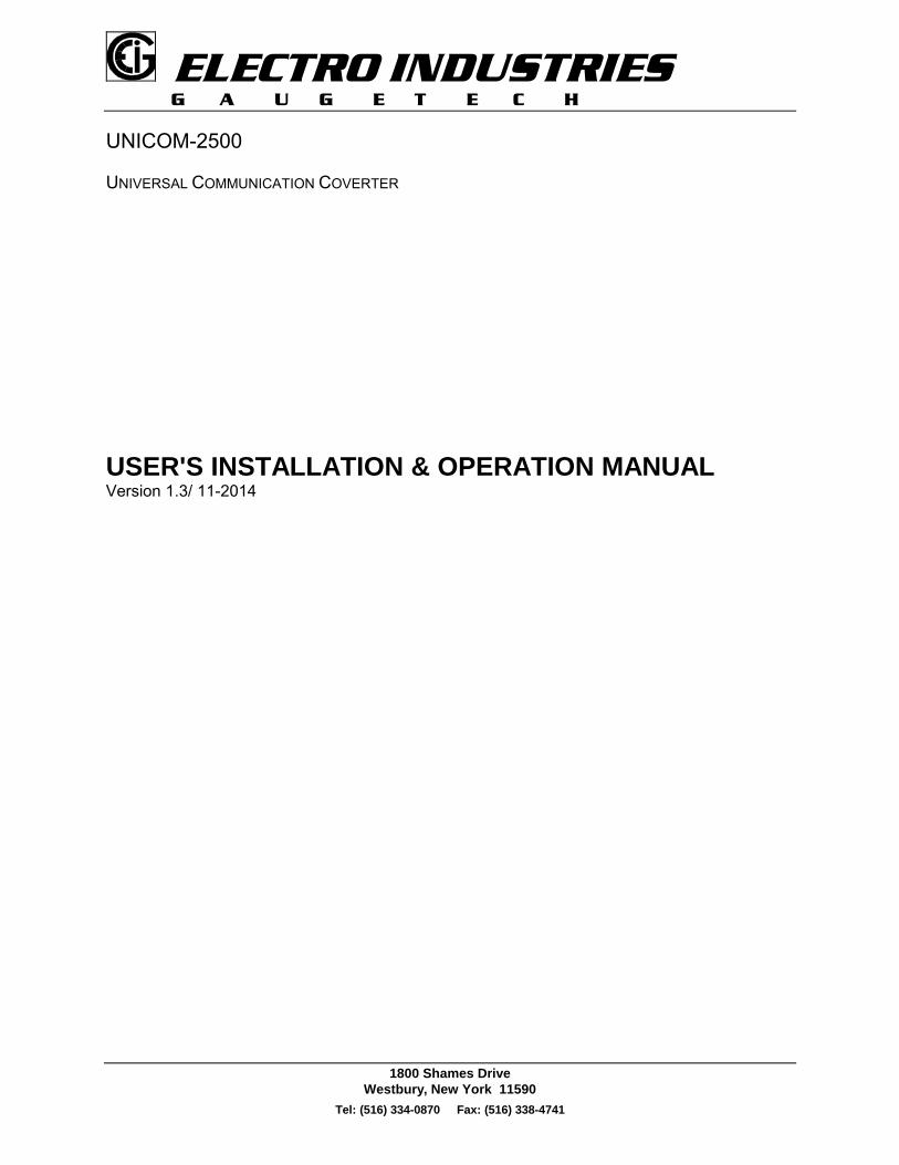
Address: Electro Industries/Gaugetech (EIG)1800 Shames Drive Westbury, New York 11590 U. S. A
For Customer or Technical Assistance, Repair and Calibration:Phone: (516) 334-0870 Fax: (516) 338-4741
Customer Support & Repair Service
Customer support is available 9:00 A.M. to 4:30 P.M., Eastern Time, Monday through Friday. Please have themodel, serial number and a detailed problem description available. If the problem concerns a particularreading, please have all meter readings available. When returning any merchandise to E.I.G., a returnauthorization number is required.
PRODUCTWARRANTY:
Electro Industries/GaugeTech warrants this product to be free from defects in material andworkmanship for a period of 1 year from date of shipment. During the warranty period, wewill, at our option, either repair or replace any product that proves to be defective.
To exercise this warranty, fax or call our customer service department. You will receiveprompt assistance and return instructions. Send the instrument, transportation prepaid, tothe address above. Repairs will be made and the instrument will be returned.
LIMITATIONOFWARRANTY:
This warranty does not apply to defects resulting from unauthorized modification, misuse,use for any reason other than electrical power monitoring. This unit is not to be used forprimary over current protection. Any protection feature in this unit is to be used for alarmor secondary protection only.
This warranty is in lieu of all other warranties, expressed or implied, including anyimplied warranty of merchantability or fitness for a particular purpose. ElectroIndustries/GaugeTech shall not be liable for any indirect, special or consequential damagesarising from any authorized or unauthorized use of any Electro Industries/GaugeTechproduct.
STATEMENTOFCALIBRATION:
This instrument has been inspected and tested in accordance with specifications publishedby Electro Industries/GaugeTech. The accuracy and calibration of this instrument aretraceable to the National Bureau of Standards through equipment which is calibrated atplanned intervals by comparison to certified standards.
DISCLAIMER: Information presented in this publication has been carefully checked for reliability;however, no responsibility is assumed for inaccuracies. The information contained in thisdocument is subject to change without notice.
COPYRIGHT: No part of this manual may be reproduced or transmitted in any form or by any means,electronic or mechanical, including photocopying, recording, or information storage orretrieval systems or any future forms of duplication, for any purpose other than thepurchaser's use, without the expressed written permission of Electro Industries/GaugeTech.
Copyright (C) 2014 Electro Industries/GaugeTech. All rights reserved.Printed in the United States of America.
*$8*(7(&+
Unicom Installation & Operation
1
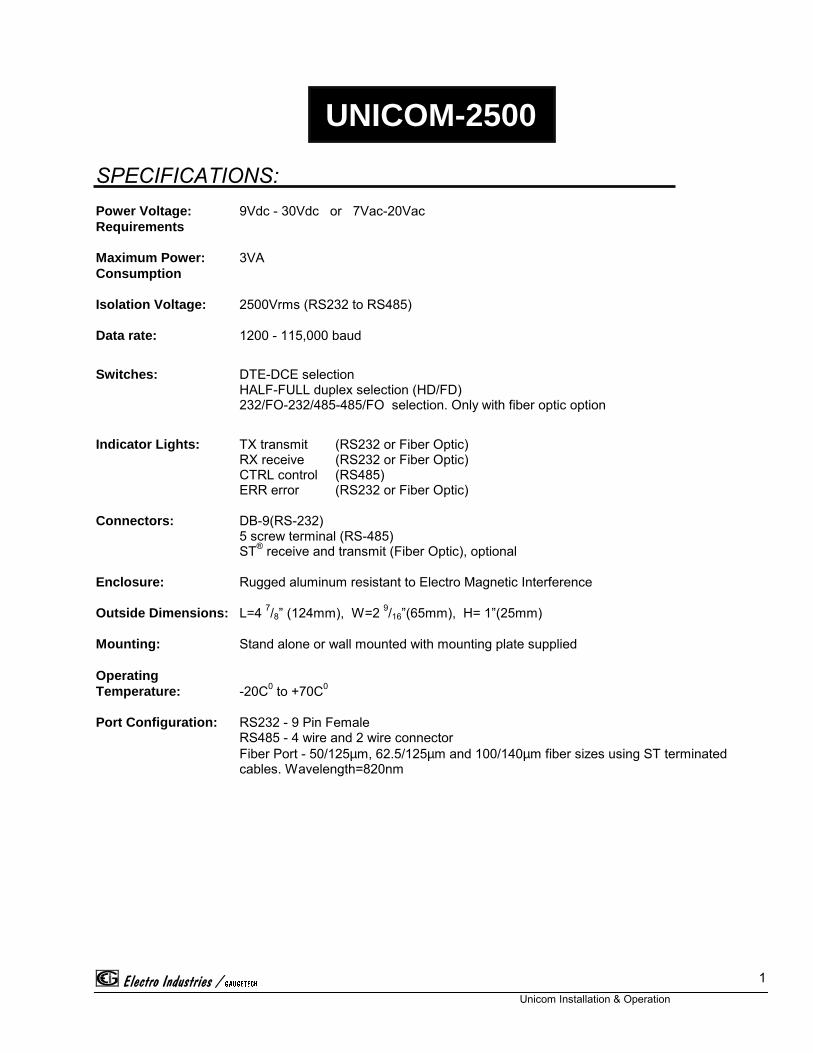
UNICOM-2500
SPECIFICATIONS:Power Voltage: 9Vdc - 30Vdc or 7Vac-20VacRequirements
Maximum Power: 3VAConsumption
Isolation Voltage: 2500Vrms (RS232 to RS485)
Data rate: 1200 - 115,000 baud
Switches: DTE-DCE selectionHALF-FULL duplex selection (HD/FD)232/FO-232/485-485/FO selection. Only with fiber optic option
Indicator Lights: TX transmit (RS232 or Fiber Optic)RX receive (RS232 or Fiber Optic)CTRL control (RS485)ERR error (RS232 or Fiber Optic)
Connectors: DB-9(RS-232)5 screw terminal (RS-485)ST® receive and transmit (Fiber Optic), optional
Enclosure: Rugged aluminum resistant to Electro Magnetic Interference
Outside Dimensions: L=4 7/8” (124mm), W=2 9/16”(65mm), H= 1”(25mm)
Mounting: Stand alone or wall mounted with mounting plate supplied
OperatingTemperature: -20C0 to +70C0
Port Configuration: RS232 - 9 Pin FemaleRS485 - 4 wire and 2 wire connectorFiber Port - 50/125µm, 62.5/125µm and 100/140µm fiber sizes using ST terminatedcables. Wavelength=820nm
*$8*(7(&+
Unicom Installation & Operation
2
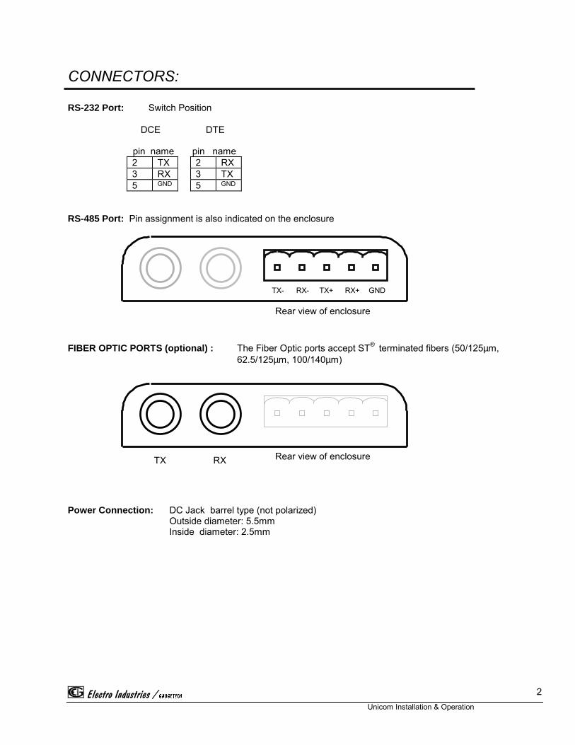
CONNECTORS:
RS-232 Port: Switch Position
DCE DTE
pin name pin name2 TX 2 RX3 RX 3 TX5 GND 5 GND
RS-485 Port: Pin assignment is also indicated on the enclosure
FIBER OPTIC PORTS (optional) : The Fiber Optic ports accept ST® terminated fibers (50/125µm, 62.5/125µm, 100/140µm)
Power Connection: DC Jack barrel type (not polarized)Outside diameter: 5.5mmInside diameter: 2.5mm
Rear view of enclosure
Rear view of enclosure
TX- RX- TX+ RX+ GND
RXTX
*$8*(7(&+
Unicom Installation & Operation
3
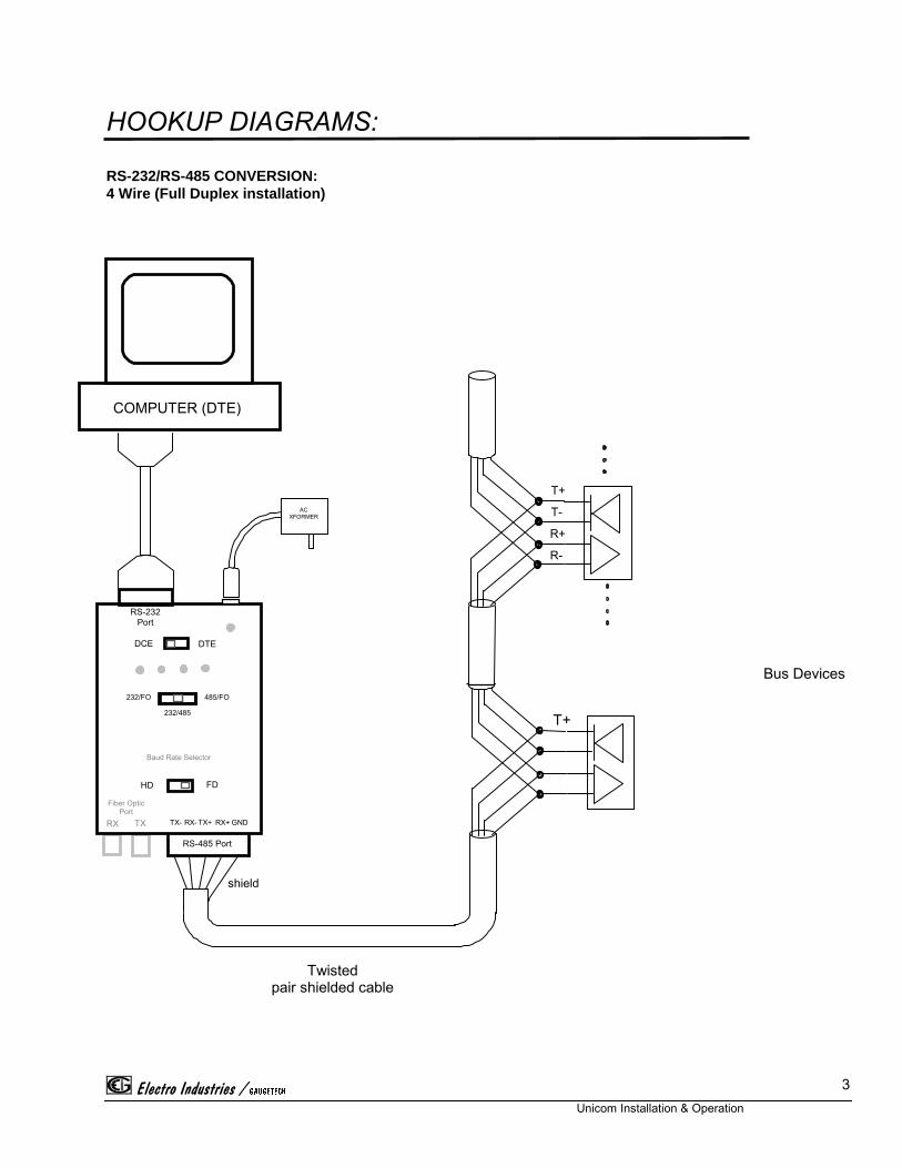
HOOKUP DIAGRAMS:
RS-232/RS-485 CONVERSION:4 Wire (Full Duplex installation)
Bus Devices
GNDRX+TX+RX-TX-TXRX
Fiber OpticPort
RS-485 Port
RS-232Port
DTE
FD
232/485
485/FO232/FO
DCE
HD
COMPUTER (DTE)
T+
shield
Twistedpair shielded cable
ACXFORMER
Baud Rate Selector
T+
T-
R+
R-
*$8*(7(&+
Unicom Installation & Operation
4
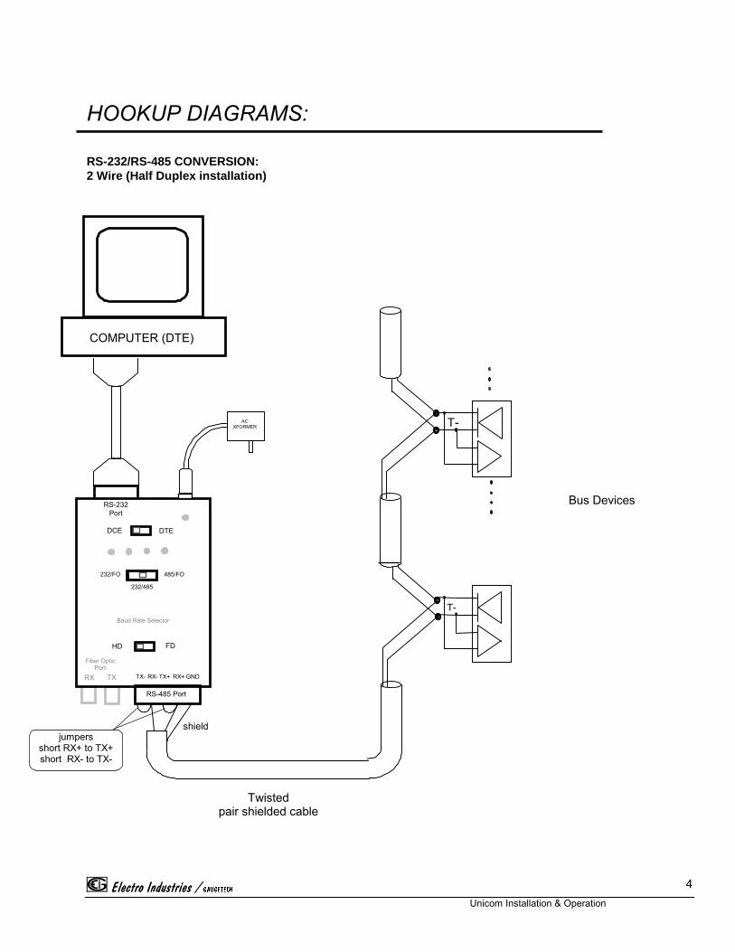
HOOKUP DIAGRAMS:
RS-232/RS-485 CONVERSION:2 Wire (Half Duplex installation)
GNDRX+TX+RX-TX-TXRX
Fiber OpticPort
RS-485 Port
RS-232Port
DTE
FD
232/485
485/FO232/FO
DCE
HD
COMPUTER (DTE)
ACXFORMER
shield
Twistedpair shielded cable
Baud Rate Selector
jumpersshort RX+ to TX+short RX- to TX-
Bus Devices
T-
T-
*$8*(7(&+
Unicom Installation & Operation
5
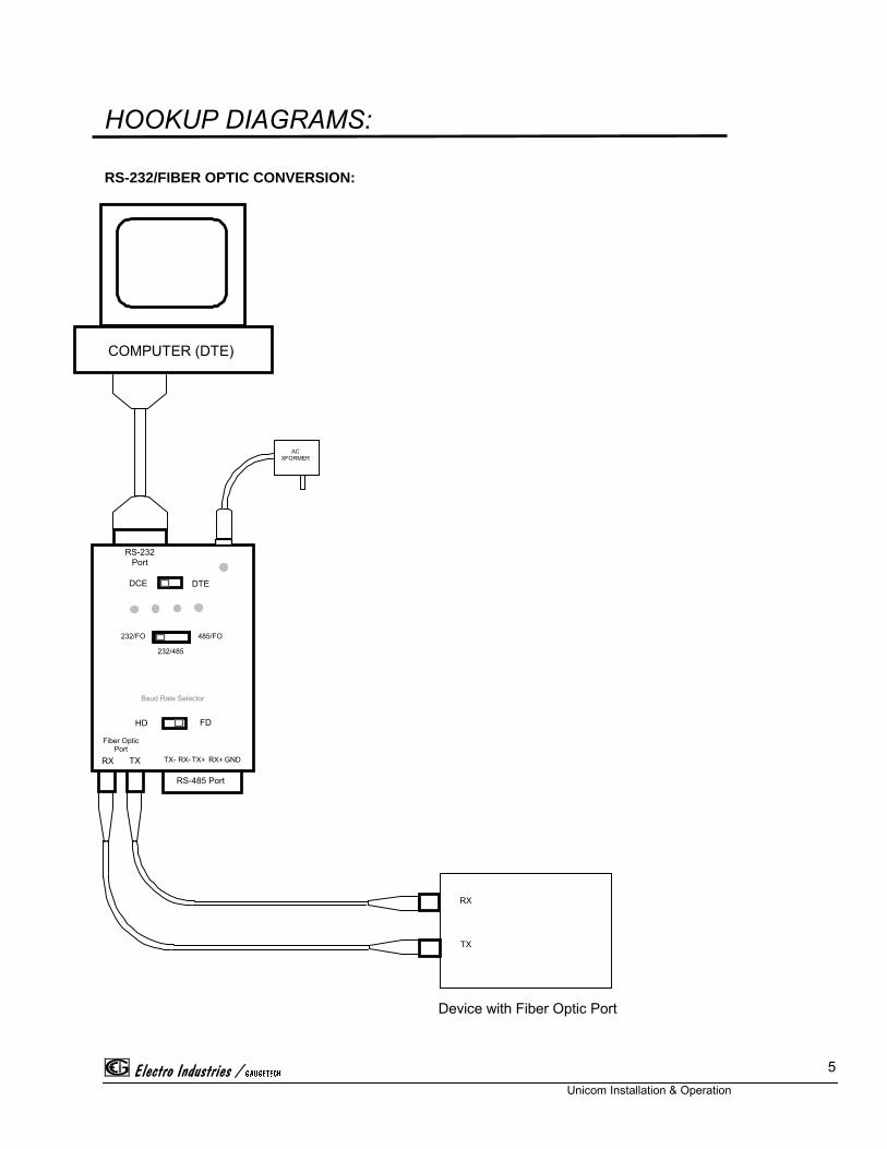
HOOKUP DIAGRAMS:
RS-232/FIBER OPTIC CONVERSION:
Device with Fiber Optic Port
GNDRX+TX+RX-TX-TXRX
Fiber OpticPort
RS-485 Port
RS-232Port
DTE
FD
232/485
485/FO232/FO
DCE
HD
COMPUTER (DTE)
ACXFORMER
Baud Rate Selector
RX
TX
*$8*(7(&+
Unicom Installation & Operation
6
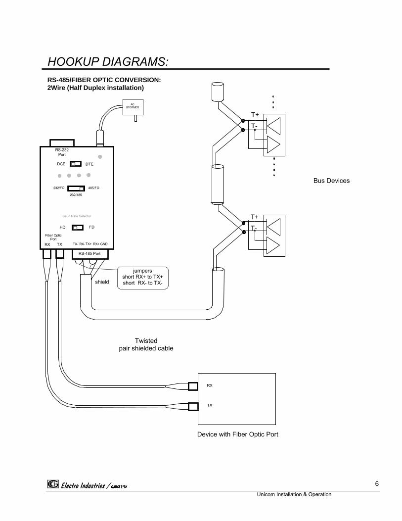
HOOKUP DIAGRAMS:RS-485/FIBER OPTIC CONVERSION:2Wire (Half Duplex installation)
GNDRX+TX+RX-TX-TXRX
Fiber OpticPort
RS-485 Port
RS-232Port
DTE
FD
232/485
485/FO232/FO
DCE
HD
ACXFORMER
Baud Rate Selector
Device with Fiber Optic Port
RX
TX
shield
jumpersshort RX+ to TX+short RX- to TX-
Twistedpair shielded cable
Bus Devices
T+
T-
T+
T-
*$8*(7(&+
Unicom Installation & Operation
7
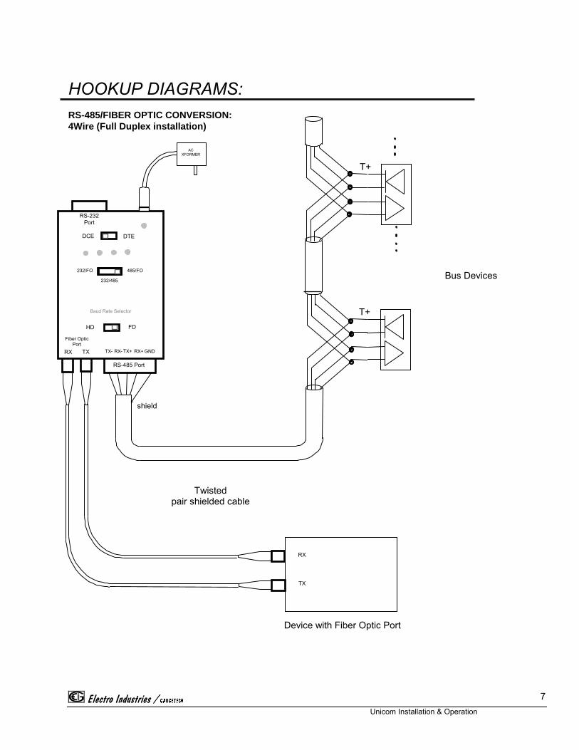
HOOKUP DIAGRAMS:RS-485/FIBER OPTIC CONVERSION:4Wire (Full Duplex installation)
GNDRX+TX+RX-TX-TXRX
Fiber OpticPort
RS-485 Port
RS-232Port
DTE
FD
232/485
485/FO232/FO
DCE
HD
ACXFORMER
Baud Rate Selector
Device with Fiber Optic Port
RX
TX
Bus Devices
shield
Twistedpair shielded cable
T+
T+
*$8*(7(&+
Unicom Installation & Operation
8
DESCRIPTION OF FEATURES
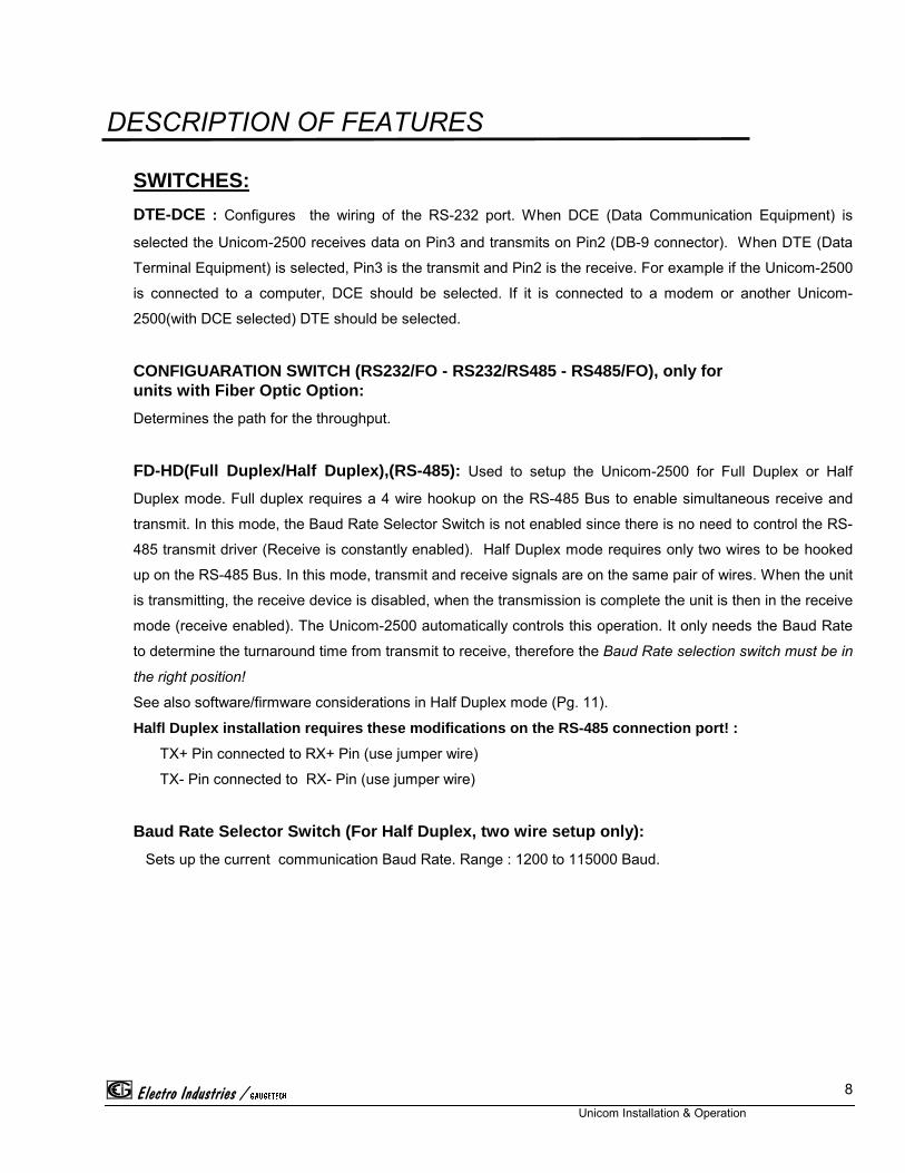
SWITCHES:
DTE-DCE : Configures the wiring of the RS-232 port. When DCE (Data Communication Equipment) is
selected the Unicom-2500 receives data on Pin3 and transmits on Pin2 (DB-9 connector). When DTE (Data
Terminal Equipment) is selected, Pin3 is the transmit and Pin2 is the receive. For example if the Unicom-2500
is connected to a computer, DCE should be selected. If it is connected to a modem or another Unicom-
2500(with DCE selected) DTE should be selected.
CONFIGUARATION SWITCH (RS232/FO - RS232/RS485 - RS485/FO), only forunits with Fiber Optic Option:
Determines the path for the throughput.
FD-HD(Full Duplex/Half Duplex),(RS-485): Used to setup the Unicom-2500 for Full Duplex or Half
Duplex mode. Full duplex requires a 4 wire hookup on the RS-485 Bus to enable simultaneous receive and
transmit. In this mode, the Baud Rate Selector Switch is not enabled since there is no need to control the RS-
485 transmit driver (Receive is constantly enabled). Half Duplex mode requires only two wires to be hooked
up on the RS-485 Bus. In this mode, transmit and receive signals are on the same pair of wires. When the unit
is transmitting, the receive device is disabled, when the transmission is complete the unit is then in the receive
mode (receive enabled). The Unicom-2500 automatically controls this operation. It only needs the Baud Rate
to determine the turnaround time from transmit to receive, therefore the Baud Rate selection switch must be in
the right position!
See also software/firmware considerations in Half Duplex mode (Pg. 11).
Halfl Duplex installation requires these modifications on the RS-485 connection port! :
TX+ Pin connected to RX+ Pin (use jumper wire)
TX- Pin connected to RX- Pin (use jumper wire)
Baud Rate Selector Switch (For Half Duplex, two wire setup only):
Sets up the current communication Baud Rate. Range : 1200 to 115000 Baud.
*$8*(7(&+
Unicom Installation & Operation
9
STATUS LIGHTS:Power: Indicates the unit is on
RX: Indicates the RS-232 or Fiber Optic port is receiving
TX: Indicates the RS-232 or Fiber Optic port is receiving
ERR: Indicates an illegal condition on the RS-232 or Fiber Optic port.A start bit is detected on the RS-232 or Fiber Optic receive line, but there is no data. This condition wouldenable the transmit driver on the RS-485 port forever which would load down the RS-485 CommunicationBus. When the ERR light comes on, Unicom-2500 automatically disables the transmit driver to preventthis unwanted situation. Such a condition is usually caused by software/firmware lockup.A new start bit will reset the unit.
CTRL: indicates the RS-485 port data direction, and is used only in Half Duplex mode. The On state indicates
transmit, the Off state indicates receive.
*$8*(7(&+
Unicom Installation & Operation
10
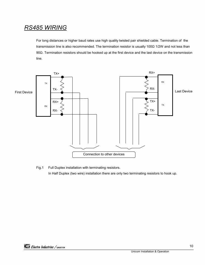
RS485 WIRING
For long distances or higher baud rates use high quality twisted pair shielded cable. Termination of the
transmission line is also recommended. The termination resistor is usually 100Ω 1/2W and not less than
90Ω. Termination resistors should be hooked up at the first device and the last device on the transmission
line.
Fig.1 Full Duplex installation with terminating resistors.
In Half Duplex (two wire) installation there are only two terminating resistors to hook up.
RX
TX RX
TX
Connection to other devices
TX+
TX-
RX+
RX-
RX+
RX-
TX+
TX-
Last DeviceFirst Device
*$8*(7(&+
Unicom Installation & Operation
11
Software/Firmware considerations when using RS-485 Half Duplex(two
wire) installation:In Half Duplex mode care must be taken in order to achieve successful operation. The automatic control
of the Unicom-2500 detects the transitions on the incoming RS-232 or Fiber Optic(optional) receive line.
When a transition occurs it enables the transmit driver of the RS-485 port. After the last transition is
detected, the unit holds transmit enable for 13 bit-times, disables the transmit driver, and then enables
the receive device of the RS-485 port. In order to avoid collisions on the transmission line, a time delay of
at least 13 bits must be inserted before transmitting back to Unicom-2500.
Electro Industries / GAUGETECH
Unicom Installation & Operation
E 12
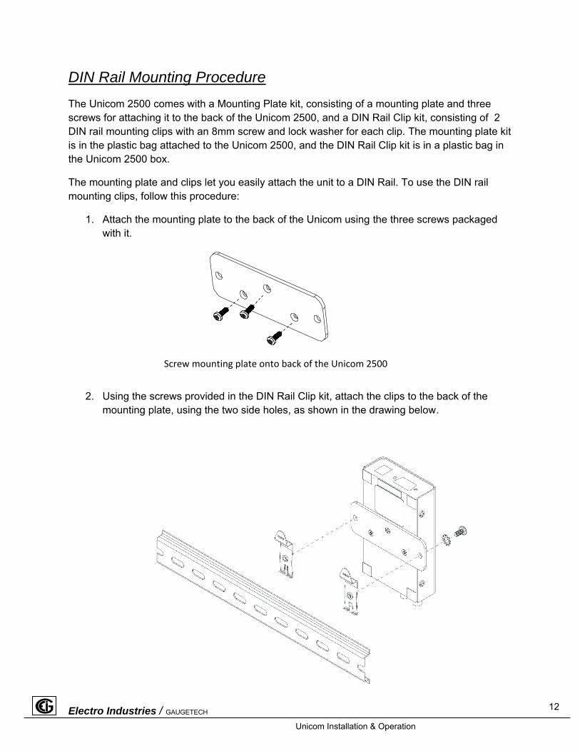
DIN Rail Mounting Procedure
The Unicom 2500 comes with a Mounting Plate kit, consisting of a mounting plate and three screws for attaching it to the back of the Unicom 2500, and a DIN Rail Clip kit, consisting of 2 DIN rail mounting clips with an 8mm screw and lock washer for each clip. The mounting plate kit is in the plastic bag attached to the Unicom 2500, and the DIN Rail Clip kit is in a plastic bag in the Unicom 2500 box.
The mounting plate and clips let you easily attach the unit to a DIN Rail. To use the DIN rail mounting clips, follow this procedure:
1. Attach the mounting plate to the back of the Unicom using the three screws packaged with it.
2. Using the screws provided in the DIN Rail Clip kit, attach the clips to the back of the mounting plate, using the two side holes, as shown in the drawing below.
Screw mounting plate onto back of the Unicom 2500
Electro Industries / GAUGETECH
Unicom Installation & Operation
E 12
a. From the front of either bracket, insert the screw into the lock washer and through the hole, and screw it into the clip using an appropriate screwdriver. Note that the clip should be positioned as shown above, with the indented side facing the back.
b. Repeat step a for the second bracket.
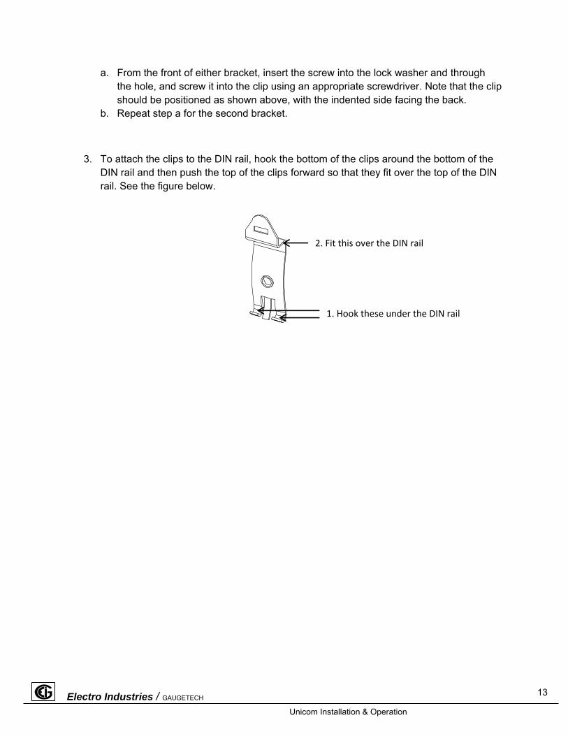
3. To attach the clips to the DIN rail, hook the bottom of the clips around the bottom of the DIN rail and then push the top of the clips forward so that they fit over the top of the DIN rail. See the figure below.
2. Fit this over the DIN rail
1. Hook these under the DIN rail
13


![New [ CS101 ] Introduction to Programming 2015 Spring - Midterm …flywing.co.kr/zokbo/file/KAIST/Common/CS101/2015_Spring... · 2017. 9. 5. · CS101 course. Your program will be](https://img.pdfslide.tips/doc/110x75/60675f28fa04bb6fd234cb3e/new-cs101-introduction-to-programming-2015-spring-midterm-2017-9-5-cs101.jpg)