Embed Size (px)
Citation preview
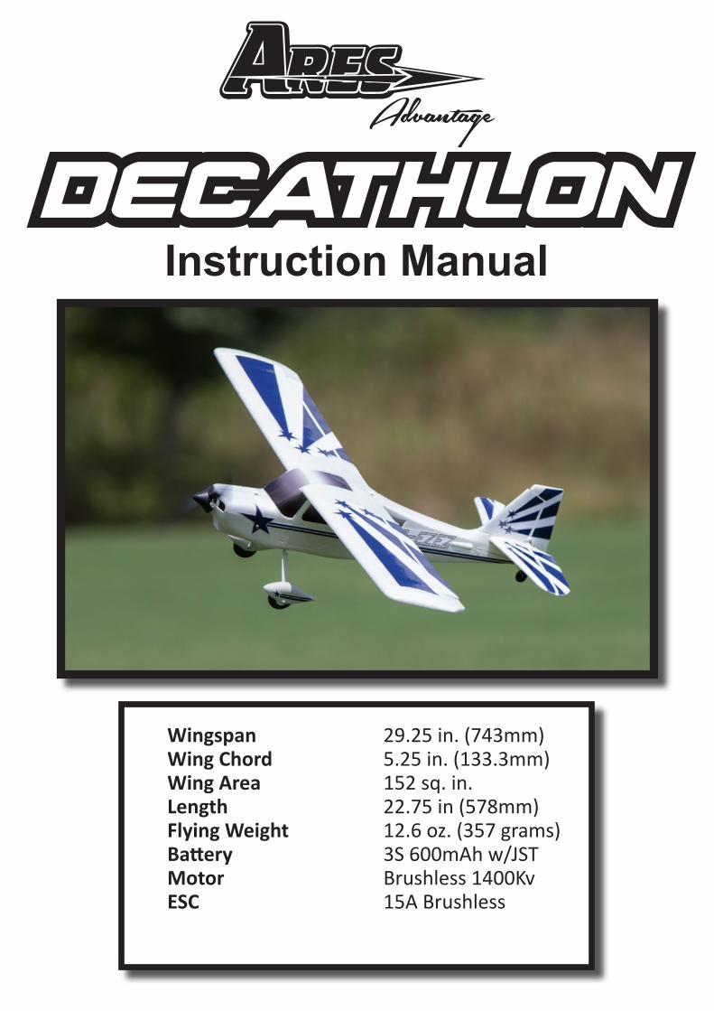
Wingspan 29.25 in. (743mm) Wing Chord 5.25 in. (133.3mm) Wing Area 152 sq. in. Length 22.75 in (578mm) Flying Weight 12.6 oz. (357 grams) Battery 3S 600mAh w/JST Motor Brushless 1400Kv ESC 15A Brushless
Instruction Manual
2
TABLE OF CONTENTS
TABLE OF CONTENTS ���������������������������������������������������������������������������������������������� 2SAFETY PRECAUTIONS ������������������������������������������������������������������������������������������� 3INTRODUCTION �������������������������������������������������������������������������������������������������������� 3GENERAL PRECAUTIONS ��������������������������������������������������������������������������������������� 4DECATHOLON 350 RTF CONTENTS ����������������������������������������������������������������������� 5REQUIRED TO COMPLETE RFR ����������������������������������������������������������������������������� 5LiPo BATTERY WARNING ����������������������������������������������������������������������������������������� 6LiPo BATTERY CHARGING ��������������������������������������������������������������������������������������� 7AIRPLANE ASSEMBLY ���������������������������������������������������������������������������������������������� 8INSTALLING FLIGHT BATTERY ������������������������������������������������������������������������������ 10CENTERING CONTROL SURFACES ����������������������������������������������������������������������11TRANSMITTER DETAILS ���������������������������������������������������������������������������������������� 12NFP OVERVIEW ������������������������������������������������������������������������������������������������������ 12NFP MODE SWITCH ����������������������������������������������������������������������������������������������� 13NFP TRIM BUTTON ������������������������������������������������������������������������������������������������� 14ESC (ELECTRONIC SPEED CONTROL) ���������������������������������������������������������������� 15FLIGHT CONTROLS ������������������������������������������������������������������������������������������������ 16CONTROL THROWS ����������������������������������������������������������������������������������������������� 17CENTER OF GRAVITY �������������������������������������������������������������������������������������������� 17FIRST FLIGHT CHECKLIST ������������������������������������������������������������������������������������ 18FLYING ��������������������������������������������������������������������������������������������������������������������� 18USING ALTERNATE RADIO SYSTEMS ������������������������������������������������������������������ 19NFP CONTROL UNIT ����������������������������������������������������������������������������������������������� 21WARRANTY ������������������������������������������������������������������������������������������������������������� 22DECATHLON REPLACEMENT PARTS ������������������������������������������������������������������� 23
3
The Ares Advantage Decathlon 350 is the ideal airplane for learning to fly RC because it includes both the technology that helps teach you how to fly and the capability to make flying fun once you’ve learned. The technology is the innovative new Aegis Natural Flight Progression (NFP) system with 3 different flying modes (Beginner, Intermediate, and Unassisted) that provide the stable assistance you need to learn to fly on your own. The capability comes from a powerful 1400KV brushless motor and 15A BL ESC combo that combined with the included 3S 600mAh Lipo battery provide plenty of power and long flight times. The NFP technology in the Decathlon is controlled from a 3-position switch on the transmitter that allows you to select one of either Beginner, Intermediate, or Unassisted Mode. Beginner Mode limits the bank angle during flight and automatically helps pilots make coordinated turns. Intermediate Mode allows greater bank angles and helps you learn how using rudder can help with controlling the airplane. In either Beginner Mode or Intermediate Mode, all you have to do if you feel you’ve lost control is let go of the sticks and the airplane quickly returns back to straight and level flight. After your flying skills have progressed to the point that you’re ready to turn off the NFP system and fly in Unassisted Mode, the technology is still there to “rescue” you if the airplane gets into trouble. All you need to do is flip the NFP control switch back into either Beginner or Intermediate Mode and you’re back in level flight! Another feature of the Aegis NFP system in the Decathlon 350 is revolutionary “Tail-Lock” technology. This feature is designed into both Beginner and Intermediate Modes and provides the benefit of automatically making coordinated flight turns look easy, even in rough air. Plus, with the NFP system on, take-offs and landings automatically become straight, smooth and stress-free, even on rough, bumpy runways. The Decathlon 350 has an attractive scale trim scheme and comes complete with everything needed to fly included in the box. In addition to the Decathlon 350 airframe, you get a 2.4GHz standard size 4-channel transmitter, a powerful LiPo battery, an AC charger, and even the AA batteries needed to power up the transmitter. A Ready-for-Receiver (without transmitter, receiver, battery, and charger) version that works with some other best-selling radio systems and includes the Aegis NFP control board is also available. With nothing extra to buy with the RTF version, you can be making your first flight toward years of RC fun within minutes of opening the box!
INTRODUCTION
SAFETY PRECAUTIONS
Failure to use this product in the intended manner as described in the following instruction can result in damage and/or personal injury. A Radio Controlled (RC) airplane/helicopter/quadcopter is not a toy! If misused it can cause serious bodily harm and damage to property.
Keep items that could become entangled away from the propeller, including loose clothing, tools, etc. Be especially sure to keep your hands, face and other parts of your body away from the propeller.
As the user of this product you are solely and wholly responsible for operating it in a manner that does not endanger yourself and others or result in damage to the product or the property of others.
This model is controlled by a radio signal that is subject to possible interference from a variety of sources outside your control. This interference can cause momentary loss of control so it is advisable to always keep a safe distance from objects and people in all directions around your model as this will help to avoid collisions and/or injury.
4
GENERAL PRECAUTIONS
• Never operate your model if the voltage of the batteries in the transmitter is too low.
• Always operate your model in an open area away from obstacles, people, vehicles, buildings, etc�
• Carefully follow the directions and warnings for this and any optional support equipment
(chargers, rechargeable batteries, etc.).
• Keep all chemicals, small parts and all electronic components out of the reach of children�
• Moisture causes damage to electronic components. Avoid water exposure to all electronic components, parts, etc. not specifically designed and protected for use in water.
• Never lick or place any portion of the model in your mouth as it could cause serious injury or even death�
This device complies with part 15 of the FCC rules. Operation is subject to the following two conditions:
(1) This device may not cause harmful interference, and
(2) this device must accept any interference received, including interference that may cause undesired operation.
Caution: Changes or modifications not expressly approved by the party responsible for compliance could void the user’s authority to operate the equipment.This product contains a radio transmitter with wireless technology which has been tested and found to be compliant with the applicable regulations governing a radio transmitter in the 2.400GHz to 2.4835GHz frequency range.
The associated regulatory agencies of the following countries recognize the noted certifications for this product as authorized for sale and use: USA
FCC INFORMATION
5
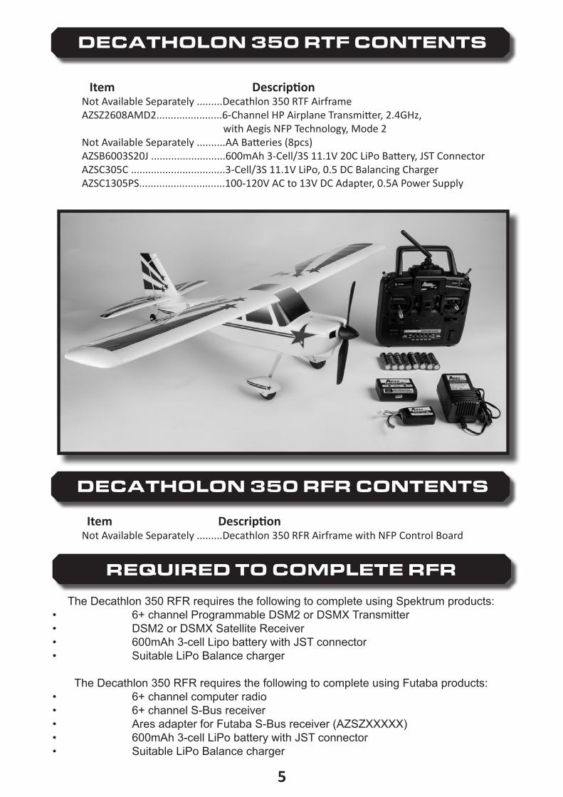
Item DescriptionNot Available Separately .........Decathlon 350 RTF AirframeAZSZ2608AMD2.......................6-Channel HP Airplane Transmitter, 2.4GHz, with Aegis NFP Technology, Mode 2Not Available Separately ..........AA Batteries (8pcs)AZSB6003S20J ..........................600mAh 3-Cell/3S 11.1V 20C LiPo Battery, JST ConnectorAZSC305C .................................3-Cell/3S 11.1V LiPo, 0.5 DC Balancing ChargerAZSC1305PS..............................100-120V AC to 13V DC Adapter, 0.5A Power Supply
DECATHOLON 350 RTF CONTENTS
DECATHOLON 350 RFR CONTENTS
Item DescriptionNot Available Separately .........Decathlon 350 RFR Airframe with NFP Control Board
REQUIRED TO COMPLETE RFR
The Decathlon 350 RFR requires the following to complete using Spektrum products:• 6+ channel Programmable DSM2 or DSMX Transmitter• DSM2 or DSMX Satellite Receiver• 600mAh 3-cell Lipo battery with JST connector• Suitable LiPo Balance charger
The Decathlon 350 RFR requires the following to complete using Futaba products:• 6+ channel computer radio• 6+ channel S-Bus receiver• Ares adapter for Futaba S-Bus receiver (AZSZXXXXX)• 600mAh 3-cell LiPo battery with JST connector• Suitable LiPo Balance charger
6
LiPo BATTERY WARNING
IMPORTANT NOTE: Lithium Polymer batteries are significantly more volatile than the alkaline, NiCd or NiMH batteries also used in RC applications. All instructions and warnings must be followed exactly to prevent property damage and/or personal injury as mishandling of LiPo batteries can result in fire. By handling, charging or using the included LiPo battery you assume all risks associated with LiPo batteries. If you do not agree with these conditions please return the complete product in new, unused condition to the place of purchase immediately.
You MUST charge the LiPo battery in a safe area away from flammable materials. NEVER charge the LiPo battery unattended at any time. When charging the battery you should ALWAYS remain in constant observation to monitor the charging process and react immediately to any potential problems that may occur.
After flying/discharging the battery you must allow it to cool to ambient/room temperature before recharging.
To charge the LiPo battery you MUST use only the included 305C balance charger or suitable LiPo battery charger. Failure to do so may result in a fire causing property damage and/or personal injury. DO NOT use a NiCd or NiMH charger.
If at any time during the charge or discharge process the battery begins to balloon or swell, discontinue charging or discharging immediately. Quickly and safely disconnect the battery, then place it in a safe, open area away from flammable materials to observe for at least 15 minutes. Continuing to charge or discharge a battery that has begun to balloon or swell can result in a fire. A battery that has ballooned or swollen even a small amount must be removedfrom service completely.
Store the battery at room temperature, approximately 68–77° Fahrenheit (F), and in a dry area for best results.
•
•
•
•
•
•
When transporting or temporarily storing the battery, the temperature range should be from approximately 40–100°F. Do not store the battery or model in a hot garage, car or direct sunlight whenever possible. Ifstoredinahotgarageorcarthebatterycanbedamagedorevencatchfire!
Do not over-discharge the LiPo battery. Discharging the LiPo battery too low can cause damage to the battery resulting in reduced power, flight duration or failure of the battery entirely.
•
•
7
LiPo cells should not be discharged to below 3.0V each under load. In the case of the 3-Cell/3S 11.1V LiPo battery used to power the Decathlon, you will not want to allow the battery to fall below 9.0V during flight.The electronic speed control (ESC) has low voltage cutoff (LVC) protection. When the flight battery voltage drops below a set point the throttle gradually is reduced. At this point the airplane will need to be landed and the battery recharged.
•
•
LiPo BATTERY CHARGING
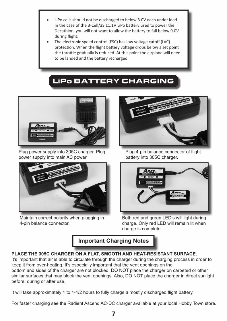
PLACE THE 305C CHARGER ON A FLAT, SMOOTH AND HEAT-RESISTANT SURFACE.It’s important that air is able to circulate through the charger during the charging process in order to keep it from over-heating. It’s especially important that the vent openings on the bottom and sides of the charger are not blocked. DO NOT place the charger on carpeted or other similar surfaces that may block the vent openings. Also, DO NOT place the charger in direct sunlight before, during or after use.
It will take approximately 1 to 1-1/2 hours to fully charge a mostly discharged flight battery.
For faster charging see the Radient Ascend AC-DC charger available at your local Hobby Town store.
Plug power supply into 305C charger. Plug power supply into main AC power.
Maintain correct polarity when plugging in 4-pin balance connector.
Plug 4-pin balance connector of flight battery into 305C charger.
Both red and green LED’s will light during charge. Only red LED will remain lit when charge is complete.
Important Charging Notes
8
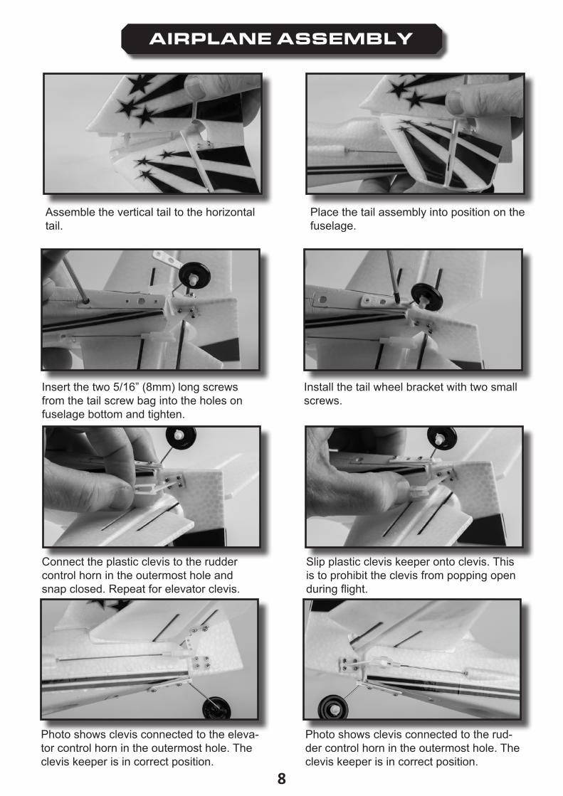
AIRPLANE ASSEMBLY
Assemble the vertical tail to the horizontal tail�
Place the tail assembly into position on the fuselage.
Insert the two 5/16” (8mm) long screws from the tail screw bag into the holes on fuselage bottom and tighten.
Connect the plastic clevis to the rudder control horn in the outermost hole and snap closed� Repeat for elevator clevis�
Photo shows clevis connected to the eleva-tor control horn in the outermost hole. The clevis keeper is in correct position.
Install the tail wheel bracket with two small screws.
Slip plastic clevis keeper onto clevis. This is to prohibit the clevis from popping open during flight.
Photo shows clevis connected to the rud-der control horn in the outermost hole. The clevis keeper is in correct position.
9
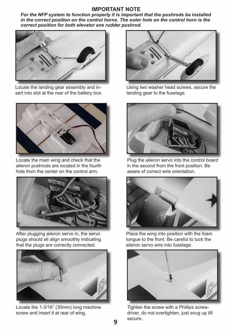
Locate the landing gear assembly and in-sert into slot at the rear of the battery box.
Locate the main wing and check that the aileron pushrods are located in the fourth hole from the center on the control arm.
After plugging aileron servo in, the servo plugs should all align smoothly indicating that the plugs are correctly connected.
Locate the 1-3/16” (30mm) long machine screw and insert it at rear of wing.
Using two washer head screws, secure the landing gear to the fuselage.
Plug the aileron servo into the control board in the second from the front position. Be aware of correct wire orientation.
Place the wing into position with the foam tongue to the front. Be careful to tuck the aileron servo wire into fuselage.
Tighten the screw with a Phillips screw-driver, do not overtighten, just snug up till secure.
IMPORTANT NOTEFor the NFP system to function properly it is important that the pushrods be installed in the correct position on the control horns. The outer hole on the control horn is the correct position for both elevator ane rudder pushrod.
10
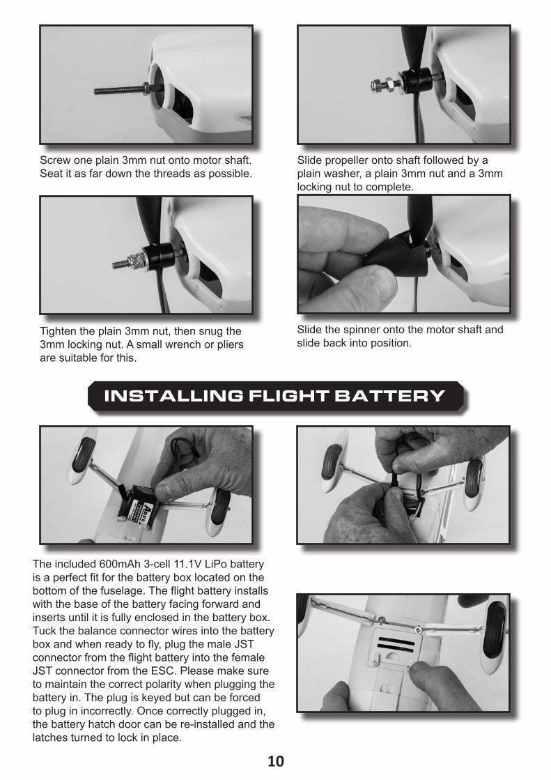
Screw one plain 3mm nut onto motor shaft. Seat it as far down the threads as possible.
Tighten the plain 3mm nut, then snug the 3mm locking nut. A small wrench or pliers are suitable for this.
Slide propeller onto shaft followed by a plain washer, a plain 3mm nut and a 3mm locking nut to complete.
Slide the spinner onto the motor shaft and slide back into position.
INSTALLING FLIGHT BATTERY
The included 600mAh 3-cell 11.1V LiPo battery is a perfect fit for the battery box located on the bottom of the fuselage. The flight battery installs with the base of the battery facing forward and inserts until it is fully enclosed in the battery box. Tuck the balance connector wires into the battery box and when ready to fly, plug the male JST connector from the flight battery into the female JST connector from the ESC. Please make sure to maintain the correct polarity when plugging the battery in. The plug is keyed but can be forced to plug in incorrectly. Once correctly plugged in, the battery hatch door can be re-installed and the latches turned to lock in place.
11
Rudder Centered
Elevator Centered
Rudder Not Centered
Elevator Not Centered
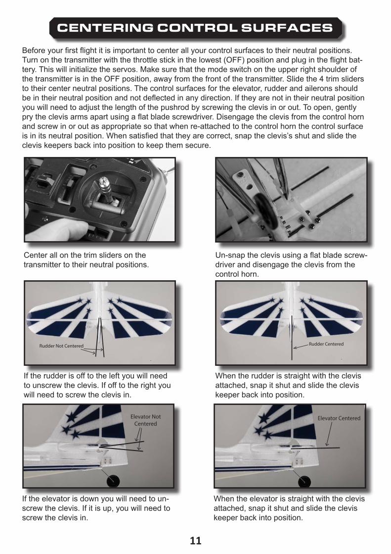
CENTERING CONTROL SURFACES
Before your first flight it is important to center all your control surfaces to their neutral positions. Turn on the transmitter with the throttle stick in the lowest (OFF) position and plug in the flight bat-tery. This will initialize the servos. Make sure that the mode switch on the upper right shoulder of the transmitter is in the OFF position, away from the front of the transmitter. Slide the 4 trim sliders to their center neutral positions. The control surfaces for the elevator, rudder and ailerons should be in their neutral position and not deflected in any direction. If they are not in their neutral position you will need to adjust the length of the pushrod by screwing the clevis in or out. To open, gently pry the clevis arms apart using a flat blade screwdriver. Disengage the clevis from the control horn and screw in or out as appropriate so that when re-attached to the control horn the control surface is in its neutral position. When satisfied that they are correct, snap the clevis’s shut and slide the clevis keepers back into position to keep them secure.
Center all on the trim sliders on the transmitter to their neutral positions.
If the rudder is off to the left you will need to unscrew the clevis. If off to the right you will need to screw the clevis in.
If the elevator is down you will need to un-screw the clevis. If it is up, you will need to screw the clevis in.
Un-snap the clevis using a flat blade screw-driver and disengage the clevis from the control horn�
When the rudder is straight with the clevis attached, snap it shut and slide the clevis keeper back into position.
When the elevator is straight with the clevis attached, snap it shut and slide the clevis keeper back into position.
12
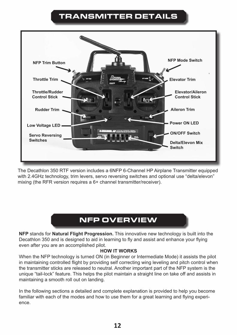
TRANSMITTER DETAILS
NFP Mode Switch
Elevator/Aileron Control Stick
Elevator Trim
Aileron Trim
ON/OFF Switch
Delta/Elevon Mix Switch
Servo Reversing Switches
Rudder Trim
Throttle/RudderControl Stick
Throttle Trim
NFP Trim Button
Low Voltage LED Power ON LED
The Decathlon 350 RTF version includes a 6NFP 6-Channel HP Airplane Transmitter equipped with 2.4GHz technology, trim levers, servo reversing switches and optional use “delta/elevon” mixing (the RFR version requires a 6+ channel transmitter/receiver).
The transmitter is also equipped with a 3-position switch and a push button that are part of the NFP (Natural Flight Progression) technology that is included in the Decathlon 350.
NFP OVERVIEW
NFP stands for Natural Flight Progression. This innovative new technology is built into the Decathlon 350 and is designed to aid in learning to fly and assist and enhance your flying even after you are an accomplished pilot.
HOW IT WORKSWhen the NFP technology is turned ON (in Beginner or Intermediate Mode) it assists the pilot in maintaining controlled flight by providing self correcting wing leveling and pitch control when the transmitter sticks are released to neutral. Another important part of the NFP system is the unique “tail-lock” feature. This helps the pilot maintain a straight line on take off and assists in maintaining a smooth roll out on landing.
In the following sections a detailed and complete explanation is provided to help you become familiar with each of the modes and how to use them for a great learning and flying experi-ence�
13
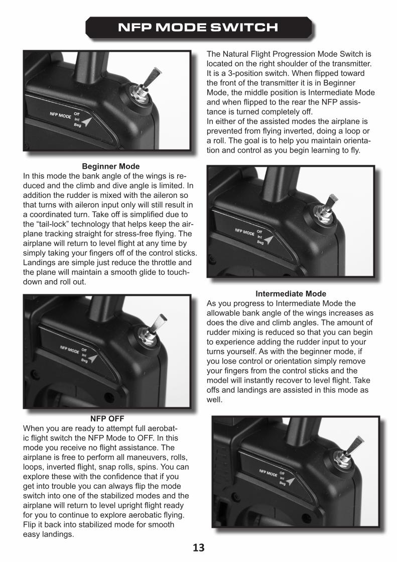
NFP MODE SWITCH
The Natural Flight Progression Mode Switch is located on the right shoulder of the transmitter. It is a 3-position switch. When flipped toward the front of the transmitter it is in Beginner Mode, the middle position is Intermediate Mode and when flipped to the rear the NFP assis-tance is turned completely off.In either of the assisted modes the airplane is prevented from flying inverted, doing a loop or a roll. The goal is to help you maintain orienta-tion and control as you begin learning to fly.
Beginner ModeIn this mode the bank angle of the wings is re-duced and the climb and dive angle is limited. In addition the rudder is mixed with the aileron so that turns with aileron input only will still result in a coordinated turn. Take off is simplified due to the “tail-lock” technology that helps keep the air-plane tracking straight for stress-free flying. The airplane will return to level flight at any time by simply taking your fingers off of the control sticks. Landings are simple just reduce the throttle and the plane will maintain a smooth glide to touch-down and roll out.
Intermediate ModeAs you progress to Intermediate Mode the allowable bank angle of the wings increases as does the dive and climb angles. The amount of rudder mixing is reduced so that you can begin to experience adding the rudder input to your turns yourself. As with the beginner mode, if you lose control or orientation simply remove your fingers from the control sticks and the model will instantly recover to level flight. Take offs and landings are assisted in this mode as well.
NFP OFFWhen you are ready to attempt full aerobat-ic flight switch the NFP Mode to OFF. In this mode you receive no flight assistance. The airplane is free to perform all maneuvers, rolls, loops, inverted flight, snap rolls, spins. You can explore these with the confidence that if you get into trouble you can always flip the mode switch into one of the stabilized modes and the airplane will return to level upright flight ready for you to continue to explore aerobatic flying. Flip it back into stabilized mode for smooth easy landings.
14
NFP TRIM BUTTON
2. Move the stick in direction of desired trim
1. Press and Hold Button
2. Move control stick in direction of desired trim response
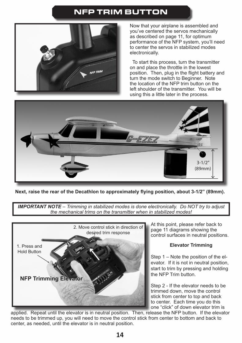
Now that your airplane is assembled and you’ve centered the servos mechanically as described on page 11, for optimum performance of the NFP system, you’ll need to center the servos in stabilized modes electronically.
To start this process, turn the transmitter on and place the throttle in the lowest position. Then, plug in the flight battery and turn the mode switch to Beginner. Note the location of the NFP trim button on the left shoulder of the transmitter. You will be using this a little later in the process.
3-1/2”(89mm)
Next, raise the rear of the Decathlon to approximately flying position, about 3-1/2” (89mm).
At this point, please refer back to page 11 diagrams showing the control surfaces in neutral positions.
Elevator Trimming
Step 1 – Note the position of the el-evator. If it is not in neutral position, start to trim by pressing and holding the NFP Trim button.
Step 2 - If the elevator needs to be trimmed down, move the control stick from center to top and back to center. Each time you do this one “click” of down elevator trim is
NFP Trimming Elevator
applied. Repeat until the elevator is in neutral position. Then, release the NFP button. If the elevator needs to be trimmed up, you will need to move the control stick from center to bottom and back to center, as needed, until the elevator is in neutral position.
IMPORTANT NOTE – Trimming in stabilized modes is done electronically. Do NOT try to adjust the mechanical trims on the transmitter when in stabilized modes!
15
1. Press and Hold Button
NFP Trimming Rudder
2. Move control stick in direction of desired trim
response
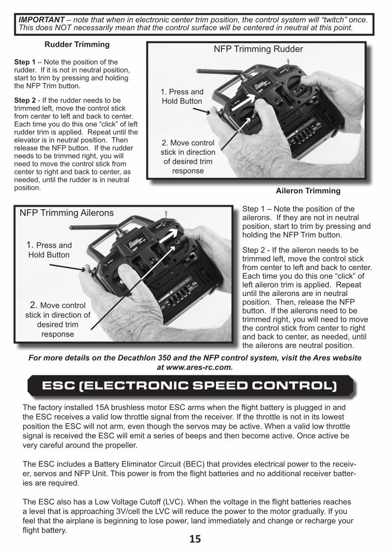
Rudder Trimming
Step 1 – Note the position of the rudder. If it is not in neutral position, start to trim by pressing and holding the NFP Trim button.
Step 2 - If the rudder needs to be trimmed left, move the control stick from center to left and back to center. Each time you do this one “click” of left rudder trim is applied. Repeat until the elevator is in neutral position. Then release the NFP button. If the rudder needs to be trimmed right, you will need to move the control stick from center to right and back to center, as needed, until the rudder is in neutral position�
1. Press and Hold Button
NFP Trimming Rudder
2. Move control stick in direction of desired trim
response
1. Press and Hold Button
2. Move control stick in direction of
desired trim response
NFP Trimming Ailerons
Aileron Trimming
Step 1 – Note the position of the ailerons. If they are not in neutral position, start to trim by pressing and holding the NFP Trim button.
Step 2 - If the aileron needs to be trimmed left, move the control stick from center to left and back to center. Each time you do this one “click” of left aileron trim is applied. Repeat until the ailerons are in neutral position. Then, release the NFP button. If the ailerons need to be trimmed right, you will need to move the control stick from center to right and back to center, as needed, until the ailerons are neutral position.
ESC (ELECTRONIC SPEED CONTROL)
The factory installed 15A brushless motor ESC arms when the flight battery is plugged in and the ESC receives a valid low throttle signal from the receiver. If the throttle is not in its lowest position the ESC will not arm, even though the servos may be active. When a valid low throttle signal is received the ESC will emit a series of beeps and then become active. Once active be very careful around the propeller. The ESC includes a Battery Eliminator Circuit (BEC) that provides electrical power to the receiv-er, servos and NFP Unit. This power is from the flight batteries and no additional receiver batter-ies are required.
The ESC also has a Low Voltage Cutoff (LVC). When the voltage in the flight batteries reaches a level that is approaching 3V/cell the LVC will reduce the power to the motor gradually. If you feel that the airplane is beginning to lose power, land immediately and change or recharge your flight battery.
IMPORTANT – note that when in electronic center trim position, the control system will “twitch” once. This does NOT necessarily mean that the control surface will be centered in neutral at this point.
For more details on the Decathlon 350 and the NFP control system, visit the Ares website at www.ares-rc.com.
16
RIG
HT
LEFT
RIG
HT
LEFT
RIGHT
LEFT
RIGHT
LEFT
RIGHTLEFT
UP
DO
WN
UP
DO
WN
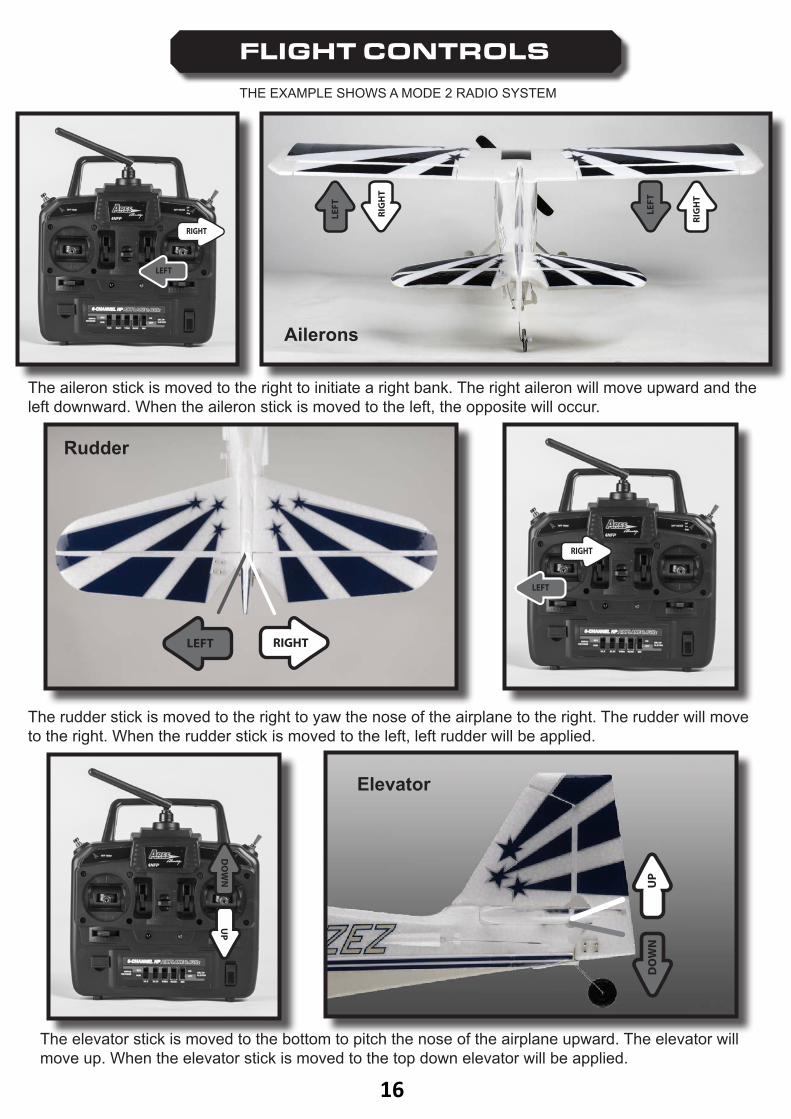
FLIGHT CONTROLS
The aileron stick is moved to the right to initiate a right bank. The right aileron will move upward and the left downward. When the aileron stick is moved to the left, the opposite will occur.
The rudder stick is moved to the right to yaw the nose of the airplane to the right. The rudder will move to the right. When the rudder stick is moved to the left, left rudder will be applied.
The elevator stick is moved to the bottom to pitch the nose of the airplane upward. The elevator will move up. When the elevator stick is moved to the top down elevator will be applied.
THE EXAMPLE SHOWS A MODE 2 RADIO SYSTEM
Ailerons
Rudder
Elevator
17
CONTROL THROWS
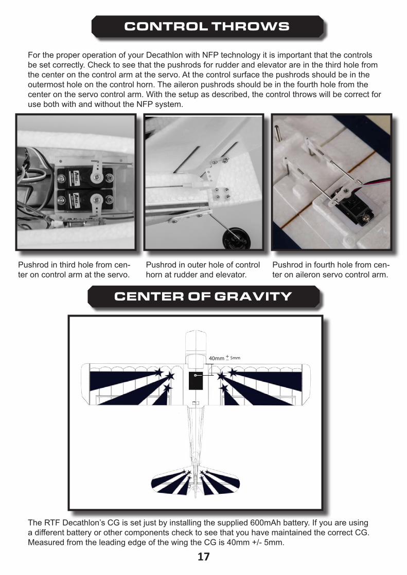
For the proper operation of your Decathlon with NFP technology it is important that the controls be set correctly. Check to see that the pushrods for rudder and elevator are in the third hole from the center on the control arm at the servo. At the control surface the pushrods should be in the outermost hole on the control horn. The aileron pushrods should be in the fourth hole from the center on the servo control arm. With the setup as described, the control throws will be correct for use both with and without the NFP system.
Pushrod in third hole from cen-ter on control arm at the servo.
Pushrod in outer hole of control horn at rudder and elevator.
Pushrod in fourth hole from cen-ter on aileron servo control arm.
CENTER OF GRAVITY
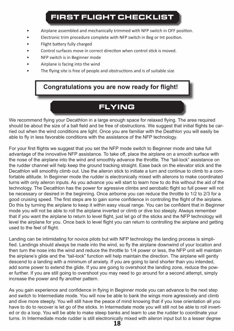
40mm +5mm
The RTF Decathlon’s CG is set just by installing the supplied 600mAh battery. If you are using a different battery or other components check to see that you have maintained the correct CG. Measured from the leading edge of the wing the CG is 40mm +/- 5mm.
18
FIRST FLIGHT CHECKLIST
• Airplane assembled and mechanically trimmed with NFP switch in OFF position.• Electronic trim procedure complete with NFP switch in Beg or Int position.• Flight battery fully charged• Control surfaces move in correct direction when control stick is moved.• NFP switch is in Beginner mode• Airplane is facing into the wind• The flying site is free of people and obstructions and is of suitable size
Congratulations you are now ready for flight!
FLYING
We recommend flying your Decathlon in a large enough space for relaxed flying. The area required should be about the size of a ball field and be free of obstructions. We suggest that initial flights be car-ried out when the wind conditions are light. Once you are familiar with the Deathlon you will easily be able to fly in less favorable conditions with the assistance of the NFP technology.
For your first flights we suggest that you set the NFP mode switch to Beginner mode and take full advantage of the innovative NFP assistance. To take off, place the airplane on a smooth surface with the nose of the airplane into the wind and smoothly advance the throttle. The “tail-lock” assistance on the rudder channel will help keep the ground tracking straight. Ease back on the elevator stick and the Decathlon will smoothly climb out. Use the aileron stick to initiate a turn and continue to climb to a com-fortable altitude. In Beginner mode the rudder is electronically mixed with ailerons to make coordinated turns with only aileron inputs. As you advance you will start to learn how to do this without the aid of the technology. The Decathlon has the power for agressive climbs and aerobatic flight so full power will not be necessary or desired in the beginning. Once airborne you can reduce the throttle to 1/2 to 2/3 for a good cruising speed. The first steps are to gain some confidence in controling the flight of the airplane. Do this by turning the airplane to keep it within easy visual range. You can be confident that in Beginner mode you will not be able to roll the airplane inverted or climb or dive too steeply. Always remember that if you want the airplane to return to level flight, just let go of the sticks and the NFP technology will level the airplane for you. Once back to level flight you can return to controlling the airplane and getting used to the feel of flight.
Landing can be intimidating for novice pilots but with NFP technology the landing process is simpli-fied. Landings should always be made into the wind, so fly the airplane downwind of your location and then turn the nose into the wind and reduce the throttle to 1/4 power or less, the NFP unit will maintain the airplane’s glide and the “tail-lock” function will help maintain the direction. The airplane will gently descend to a landing with a minimum of anxiety. If you are going to land shorter than you intended, add some power to extend the glide. If you are going to overshoot the landing zone, reduce the pow-er further. If you are still going to overshoot you may need to go around for a second attempt, simply increase the power and fly another pattern.
As you gain experience and confidence in flying in Beginner mode you can advance to the next step and switch to Intermediate mode. You will now be able to bank the wings more agressively and climb and dive more steeply. You will still have the peace of mind knowing that if you lose orientation all you have to do to recover is let go of the sticks. In Intermediate mode you will still not be able to roll invert-ed or do a loop. You will be able to make steep banks and learn to use the rudder to coordinate your turns. In Intermediate mode rudder is still electronically mixed with aileron input but to a lesser degree
19
USING ALTERNATE RADIO SYSTEMS
Instructions for use with Spektrum™ DSM2® or DSMX® Transmitter and Satellite Receiver
INSTALLATION AND CONFIGURATION
To fly your Decathlon using a Spektrum™ compatible radio system, you will need a DSM2® or DSMX® compatible satellite receiver and a Spektrum™ compatible transmitter in Airplane mode with 6 channels or more. Connect the Spektrum™ DSM2® or DSMX® satellite receiver to the receiver port on the NFP control unit and secure it in an appropriate location in the fuselage using double-sided adhesive�
Assign the channels on the transmitter as follows:Channel 1: ThrottleChannel 2: AileronChannel 3: ElevatorChannel 4: RudderChannel 5: NFP mode selection switchChannel 6: Stabilized Mode Trim
The directions for Throttle, Aileron, Elevator, and Rudder should be normal (not reversed). We recommend a -100 to 100 setting for these channels, although you are welcome to change these settings or use dual rate switches to optimize flight experience.
If possible, Channel 5 should be assigned to a three-position switch. If no such switch is available, a two-position switch can be used, although only two of the NFP flight modes will be available. If a three-position switch is available, the NFP mode selection switch should output 100% when flipped all the way down (NFP Beginner Mode), 0% in the middle position (NFP Intermediate Mode), and -100% when flipped all the way up (NFP Off). If a two-position switch is used, only two modes can be selected, and the pilot will have to decide which settings they prefer.
If possible, Channel 6 should be assigned to a contact switch that returns to the normal position when released. The channel should be configured such that it assumes a value of 100% when the button/switch is depressed. In this case, the Decathlon will be in the normal flight mode. When the button/switch is depressed, the channel should assume a value of -100%, and the airplane will be in NFP trim mode.
than in Beginner mode. This means that in order to fly coordinated turns you will need to apply some rudder along with the aileron input to make a smooth turn. If you do not add some additional rudder input in the direction of the turn the airplane will still turn but it will not be as coordinated a turn as you were doing in Beginner mode. As you gain some confidence and experience in adding some rudder during your turns you will see an improvement in how smoothly you are flying. Take off and landing in Intermediate mode are similar to Beginner mode, the NFP technology is active and assists in both aspects of the flight.
When you are comfortable with Intermediate mode you are ready to move on to Unassisted mode where all the NFP technology is turned off. In this mode the stabilization and “tail-lock” functions are inactive. In this mode the airplane is totally aerobatic and can perform loops, rolls, inverted flight and many other maneuvers. You can begin to explore this expanded realm of flight with the total con-fidence that if you become disoriented or lose control of the airplane that you can be back to level flight with the flip of a switch. While learning expanded flight maneuvers always give yourself suffi-cient altitude to recover from the unexpected.
We hope that you enjoy learning to fly the Decathlon and have many enjoyable flights.
20
Instructions for use with Futaba® Transmitter and S.BUS ReceiverINSTALLATION AND CONFIGURATION
To fly your Decathlon with a Futaba® radio system, you will need a programmable Futaba® compatible transmitter in airplane mode with 6 channels or more and a Futaba compatible S.BUS receiver with 6 channels or more. The Decathlon supports both S-FHSS and FASST radio protocols. You will also need an adapter to connect the receiver to the S.BUS receiver (AZSZ2607).
Connect the S.BUS adapter to the NFP control unit using the AZSZ2607 S.BUS adapter cable. Make sure to use the correct polarity such that the brown GROUND wire on the adapter connects to the GROUND pin on the S�BUS adapter� DO NOT connect the servo outputs on the S.BUS receiver to the control unit, as doing so may damage the devices and will cause the airplane to function incorrectly. Secure the receiver in an appropriate location in the fuselage using double-sided adhesive�Channel 1: AileronChannel 2: ElevatorChannel 3: ThrottleChannel 4: RudderChannel 5: NFP mode selection switchChannel 6: Stabilized Mode Trim
Channels 1 and 2 should be in the Reverse mode, and channels 3 and 4 should be Normal. We recommend a -100 to 100 setting for these channels, although you are welcome to change these settings or use dual rate switches to optimize flight experience.
If possible, Channel 5 should be assigned to a three-position switch. If no such switch is available, a two-position switch can be used, although only two of the NFP flight modes will be available. If a three-position switch is available, the NFP mode selection switch should output 100% when flipped all the way down, 0% in the middle position, and -100% when flipped all the way up. If a two-position switch is used, only two modes can be selected, and the pilot will have to decide which settings they prefer�
If possible, Channel 6 should be assigned to a contact switch that returns to the normal position when released. Then channel should be configured such that it assumes a value of 100% when the button/switch is depressed. In this case, the Decathlon will be in the normal flight mode. When the button/switch is not depressed, the channel should assume a value of -100%, and the airplane will be in NFP trim mode.
BINDING
For instructions for binding Futaba® compatible radio systems, please refer to the appropriate instruction manuals.
BINDING
If you are using the DSM2® protocol, you will need to place a Spektrum™ Bind Plug on the Aux/Bind servo connector on the NFP control unit before binding. If you are using the DSMX® protocol, this is not necessary. To enter bind mode, with the transmitter powered off, press and hold the button on the NFP control unit while plugging in the battery. The receiver will start to blink rapidly to indicate that it is in bind mode. Then, power on the transmitter in bind mode. The LED indicator on the receiver should become solid to indicate a solid link. You can now remove the Bind Plug (if connected). You will need to unplug the battery and plug it back in to re-initialize the system. If the bind is not successful at first, please repeat the process�
You can also use a separate system to bind the receiver and transmitter and then install the already bound receiver into the airplane.
*Spektrum, DSM2, and DSMX are registered trademarks of Horizon Hobby
21
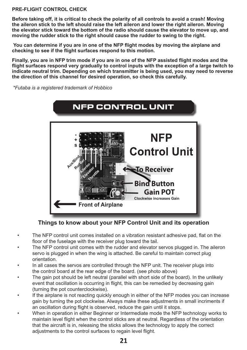
NFP CONTROL UNIT
Aux/Bind
Rudder
Ailero
n
Elevato
r
Throttle
-+s
Clockwise increases Gain
Bind ButtonGain POT
To Receiver
NFP Control Unit
Front of Airplane
• The NFP control unit comes installed on a vibration resistant adhesive pad, flat on the floor of the fuselage with the receiver plug toward the tail.• The NFP control unit comes with the rudder and elevator servos plugged in. The aileron servo is plugged in when the wing is attached. Be careful to maintain correct plug orientation�• In all cases the servos are controlled through the NFP unit. The receiver plugs into the control board at the rear edge of the board. (see photo above)• The gain pot should be left neutral (parallel with short side of the board). In the unlikely event that oscillation is occurring in flight, this can be remedied by decreasing gain (turning the pot counterclockwise). • If the airplane is not reacting quickly enough in either of the NFP modes you can increase gain by turning the pot clockwise. Always make these adjustments in small incriments if an oscillation during flight is observed, reduce the gain until it stops.• When in operation in either Beginner or Intermediate mode the NFP technology works to maintain level flight when the control sticks are at neutral. Regardless of the orientation that the aircraft is in, releasing the sticks allows the technology to apply the correct adjustments to the control surfaces to regain level flight.
Things to know about your NFP Control Unit and its operation
PRE-FLIGHT CONTROL CHECK
Before taking off, it is critical to check the polarity of all controls to avoid a crash! Moving the aileron stick to the left should raise the left aileron and lower the right aileron. Moving the elevator stick toward the bottom of the radio should cause the elevator to move up, and moving the rudder stick to the right should cause the rudder to swing to the right.
You can determine if you are in one of the NFP flight modes by moving the airplane and checking to see if the flight surfaces respond to this motion.
Finally, you are in NFP trim mode if you are in one of the NFP assisted flight modes and the flight surfaces respond very gradually to control inputs with the exception of a large twitch to indicate neutral trim. Depending on which transmitter is being used, you may need to reverse the direction of this channel for desired operation, so check this carefully.
*Futaba is a registered trademark of Hobbico
2222
30-Day Limited Warranty Term Period:
We warranty that the Product(s) purchased (the “Product”) will be free from defects in materials and work manship when the product is new (before being used) for the limited warranty term period, 30 days, from the date of purchase by the Purchaser.
If you believe a defect in material, workmanship, etc. was not apparent when the Product was new and only became evident after the Product was used, take the following steps. If you purchased the Product at a HobbyTown store, please contact your local HobbyTown store for warranty support and/or service. If you purchased the Product from the Firelands website, use the contact information found under the Support heading to contact Firelands directly.
If you contact Firelands, you may be asked to send the product to Firelands, at your cost, for inspection. Provided the warranty conditions have been met within the warranty term period, the components that are found to be defective, incorrectly manufactured or assembled may be repaired or replaced, at the sole discretion of Firelands. Your warranty item will be returned to you at Firelands’ expense. In the event your product needs repair or a replacement part that is not covered by this warranty, your local HobbyTown store or Firelands can assist you with support and in obtaining the genuine replacement parts to repair your Prod uct. Firelands will charge $40.00 per hour plus the cost of replacement parts to service your vehicle if after contacting you, you so authorize such repairs. Your product will be returned to you at your expense.
If you purchased your Product from a HobbyTown Internet site not affiliated with a local store, please consult that site for its support and service policies. You can also find more information at:
www.Hobbytown.com
or by emailing [email protected]
or call 800-205-6773
WARRANTY
• In addition to the leveling function in Beginner mode, the NFP technology also mixes some rudder with the ailerons to produce coordinated turns even when only the aileron stick is used for turns. Even though rudder is mixed automatically, additional rudder can be added by moving the rudder stick along with the aileron stick. • As you progress to Intermediate mode rudder mixing is still active but at a reduced rate. To make coordinated turns in this mode you will need to apply some rudder with the rudder stick along with the aileron stick movement. By practicing this skill you will become a more confident and competent pilot.• The “Tail-lock” feature of the NFP technology is a benifit to pilots of all experience levels. It actively works whenever one of the NFP modes are selected and helps the airplane maintain a direction both on the ground and in the air. When the NFP unit detects a change in the yaw of the airplane it applies the opposite rudder input to dampen out the effect. This is very helpful when taking off, particularly in a crosswind, as it helps maintain a smooth and straight take off roll. The same is true for landings, the “Tail-lock” technology helps you make a smooth approach and maintain a straight roll out after touchdown.
23
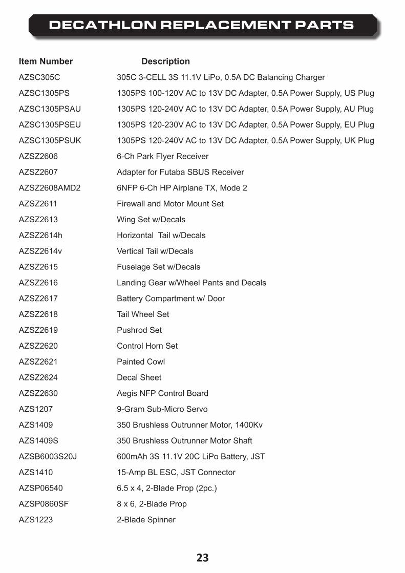
DECATHLON REPLACEMENT PARTS
Item Number Description
AZSC305C 305C 3-CELL 3S 11.1V LiPo, 0.5A DC Balancing Charger
AZSC1305PS 1305PS 100-120V AC to 13V DC Adapter, 0.5A Power Supply, US Plug
AZSC1305PSAU 1305PS 120-240V AC to 13V DC Adapter, 0.5A Power Supply, AU Plug
AZSC1305PSEU 1305PS 120-230V AC to 13V DC Adapter, 0.5A Power Supply, EU Plug
AZSC1305PSUK 1305PS 120-240V AC to 13V DC Adapter, 0.5A Power Supply, UK Plug
AZSZ2606 6-Ch Park Flyer Receiver
AZSZ2607 Adapter for Futaba SBUS Receiver
AZSZ2608AMD2 6NFP 6-Ch HP Airplane TX, Mode 2
AZSZ2611 Firewall and Motor Mount Set
AZSZ2613 Wing Set w/Decals
AZSZ2614h Horizontal Tail w/Decals
AZSZ2614v Vertical Tail w/Decals
AZSZ2615 Fuselage Set w/Decals
AZSZ2616 Landing Gear w/Wheel Pants and Decals
AZSZ2617 Battery Compartment w/ Door
AZSZ2618 Tail Wheel Set
AZSZ2619 Pushrod Set
AZSZ2620 Control Horn Set
AZSZ2621 Painted Cowl
AZSZ2624 Decal Sheet
AZSZ2630 Aegis NFP Control Board
AZS1207 9-Gram Sub-Micro Servo
AZS1409 350 Brushless Outrunner Motor, 1400Kv
AZS1409S 350 Brushless Outrunner Motor Shaft
AZSB6003S20J 600mAh 3S 11.1V 20C LiPo Battery, JST
AZS1410 15-Amp BL ESC, JST Connector
AZSP06540 6.5 x 4, 2-Blade Prop (2pc.)
AZSP0860SF 8 x 6, 2-Blade Prop
AZS1223 2-Blade Spinner

www.Ares-RC.com©2014
Rev 1�010/1714