Embed Size (px)
Citation preview
Instytut Fizyki Doświadczalnej Wydział Matematyki, Fizyki i Informatyki
UNIWERSYTET GDAŃSKI
Instytut Fizyki Doświadczalnej 1.
Experiment 31 : Determination of the Landé factor using electron paramagnetic resonance (EPR)
I. Background theory.
1. Electron energy levels in atoms. 2. Quantum numbers of electron energy levels. 3. Magnetic moment of the electron shell of an atom.
4. Electron spin magnetic moment. 5. Bohr magneton. 6. Para and diamagnetic atoms. 7. The total magnetic moment of an atom.
8. Relationship between the nuclear magneton and Bohr magneton. 9. Atoms in a constant magnetic field:
a) Larmor precession; b) Larmor precession frequency; c) Landé factor.
10. Resonance interactions of atomic magnetic moments in a fixed and a variable magnetic field (in classical terms).
11. Paramagnetic magnetisation in fixed and variable magnetic fields. 12. Energy absorption from a varying magnetic field by magnetised paramagnetic substances:
a) spin relaxation and its effect on absorption line widths; b) spin – grid relaxation and its impact on energy absorption from a varying magnetic field.
13. Quantum description of electron paramagnetic resonance: a) energy level splitting of paramagnetic atoms in an external magnetic field; b) filling of the magnetic sublevels; c) resonance transition frequency in electron paramagnetic resonance.
14. Electron paramagnetic resonance spectrum: a) EPR absorption line profiles; b) half-width of EPR lines; c) fine structure of EPR spectra.
15. Construction and operation of microwave spectrometers (with resonance and reflective cavity resonance): a) klystron as a source of microwaves; b) resonance cavity; c) microwave detector.
16. Optimal microwave detector operating conditions for measuring EPR signals with microwave spectrometers.
17. Applications of electron paramagnetic resonance. 18. Zeeman effect in weak and strong magnetic fields.

Instytut Fizyki Doświadczalnej 2.
Experiment 31 : Determination of the Landé factor using electron paramagnetic resonance (EPR)
II. Experimental tasks.
1. Refer to the experimental setup shown in Picture 1.
Picture 1. Experimental setup for measuring EPR absorption lines: 1 – EPR resonance cavity; 2 –
EPR power supply; 3 – universal power supply; 4 – dual-channel oscilloscope; 5 – digital multimeter (ammeter); 6 – digital multimeter (voltmeter); 7 - teslameter; 8 – switch.
2. Connect the apparatus as shown in Figure 2 and following the supervisor’s instructions.
3. Set switch 8 in Picture 1 to position 0. 4. Turn on the power to each system component.
Figure 2. Circuit diagram of components to measure EPR resonance: 1 – resonance cavity; 2 – EPR power supply; 3 – universal power supply; 4 – dual-
channel oscilloscope; 5, 6 – digital multimeters.

Instytut Fizyki Doświadczalnej 3.
Experiment 31 : Determination of the Landé factor using electron paramagnetic resonance (EPR)
Power switches for the oscilloscope 4, Picture 1, digital multimeter 5, Picture 1 and EPR power supply 2, Picture 1 are on their front panels while those for the teslameter and universal power supply are found on the rear of their housings.
5. Set the oscilloscope in X-Y mode by pressing: Menu/Zoom, Time Base in the Horizontal menu, and turning the dial to choose the correct mode. Then use the keys: Menu/Zoom, Sa Rate and turn the dial to set a sampling frequency of 100.0 kSa.
6. Ensure that the test sample is inside the resonance cavity. 7. Balance the bridge by observing the voltage on the meter 6, Picture 1 and following these
steps: Set the resistance knob R 3, Picture 3 to the middle of the range; rotate the capacitance dial C, 2, Picture 3 all the way to the left. Press button 8, Picture 5 and turn dial 12, Picture 5 to zero the meter.
Picture 3. Left and right view of the EPR resonance cavity: 1 – EPR signal output; 2 –capacitance dial C; 3 – resistance dial R; 4 – high-frequency input; 5 – place for the sample.
8. Set a constant voltage across the coil to about 12 V with dial 2, Picture 4, and use dial 3, Picture 4 to set the current to 1,5 A.
Picture 4. Universal power supply front panel: 1 – output voltage; 2 – voltage dial; 3 – current dial; 4 – AC voltage selection; 5 – AC voltage output.
Instytut Fizyki Doświadczalnej 4.
Experiment 31 : Determination of the Landé factor using electron paramagnetic resonance (EPR)
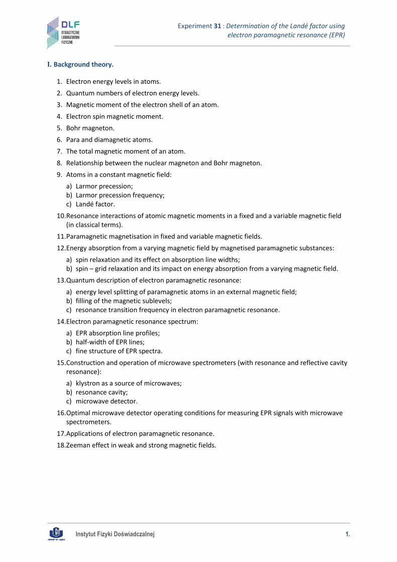
Set the AC voltage to 4 V by appropriately setting 4, Picture 4 and set the EPR signal gain to the middle of the range by turning dial 11, Picture 5.
9. Look for the sample absorption signal by following these steps: set switch 8 to position 1, press button 12, Picture 5, and while watching the image on the oscilloscope and the voltage on the meter 6, Picture 1, turn the capacitance dial C, 2, Picture 3 and dial 12, Picture 5 such that the image on the oscilloscope is symmetrical and the meter reads zero voltage.
10. Set the phase of the observed signals with knob 12, Picture 5 so that the absorption images overlap while using dial 2, Picture 4 to centre the oscilloscope images and save them using the instructions in the Appendix.
11. Read off the current and calculate the value of the Landé factor. 12. Investigate the effect of dial 11, Picture 5 on the shape of the signal.
Picture 5, Front panel of the EPR power supply: 1 – power switch; 2 – high-frequency output; 3 - 6V/50Hz internal phase shift output; 4 – phase shifter output; 5 – EPR resonator signal input; 6 – output to the digital meter; 7 – output to the oscilloscope; 8 – bridge balance check button; 9
– button to select oscilloscope signal only; 10 – button to select signal for the oscilloscope and meter; 11 – gain dial; 12 – zero dial; 13 – phase dial.
Instytut Fizyki Doświadczalnej 5.
Experiment 31 : Determination of the Landé factor using electron paramagnetic resonance (EPR)
III. Apparatus.
1. EPR resonance chamber with Helmholtz coils. 2. EPR power supply. 3. Universal power supply.
4. Two digital multimeters. 5. DSO 1002 A oscilloscope. 6. Teslameter. 7. DPPH (Diphenylpicrylhydrazyl) sample.
8. Switch.
IV. Literature.
1. R.G. Marcley – “Apparatus Drawings Project. Report Number 19. Apparatus for Electron Paramagnetic Resonance at Low Fields”, Am. J. Phys. 29, 492 (1961).
2. R.S. Alger – “Electron Paramagnetic Resonance: techniques and applications”, N.Y. 1968. 3. V. Acosta, C.L. Cowan, B.J. Graham – “Essentials of Modern Physics”, Harper & Row, Publishers,
New York 1973. 4. A. Reimann – “Physics”, Vol. III. “Modern Physics”, Harper & Row, Publishers Inc., 1973. 5. J.A. Weil, J.R. Bolton – “Electron Paramagnetic Resonance: Elementary Theory and Practical
Applications”, Wiley, New York 2001. 6. R.P. Feynman, R. Leighton, M. Sands – “The Feynman Lectures on Physics”, Vol. II. Part 2.,
Addison – Wesley, 2005.
Instytut Fizyki Doświadczalnej 6.
Experiment 31 : Determination of the Landé factor using electron paramagnetic resonance (EPR)
Appendix Reading and saving signals with the DSO 1002 A oscilloscope (Agilent Technology)
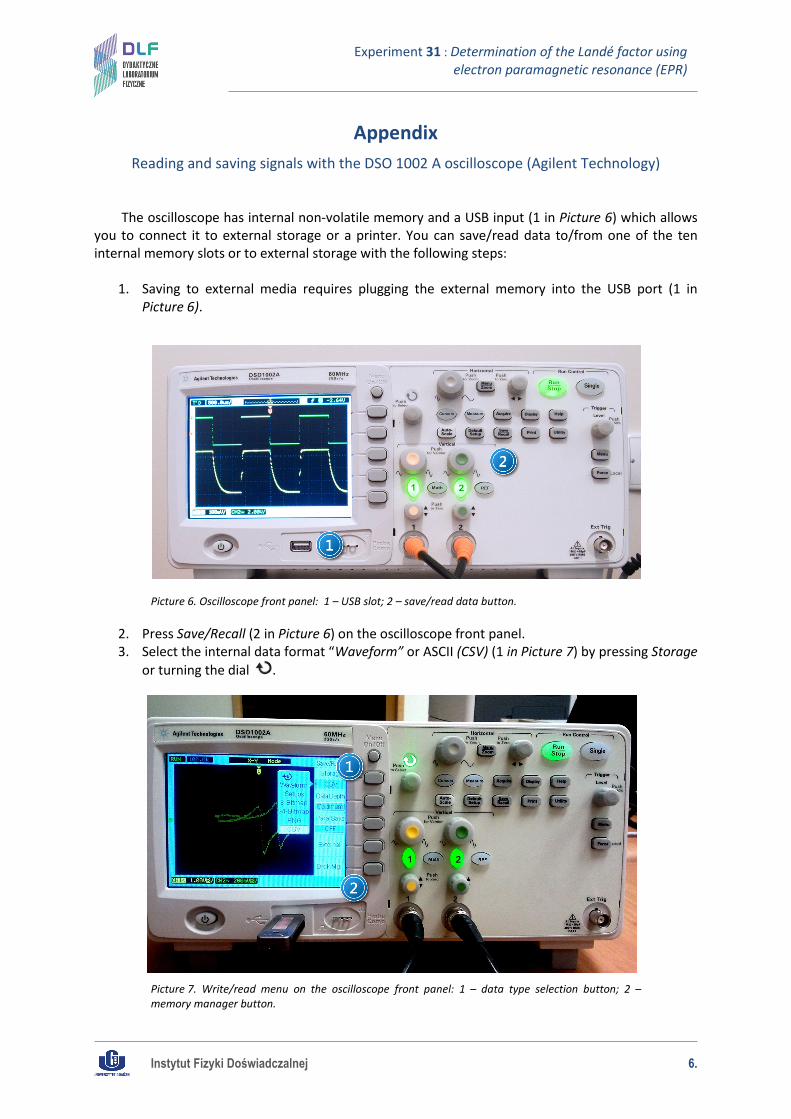
The oscilloscope has internal non-volatile memory and a USB input (1 in Picture 6) which allows you to connect it to external storage or a printer. You can save/read data to/from one of the ten internal memory slots or to external storage with the following steps:
1. Saving to external media requires plugging the external memory into the USB port (1 in
Picture 6).
Picture 6. Oscilloscope front panel: 1 – USB slot; 2 – save/read data button.
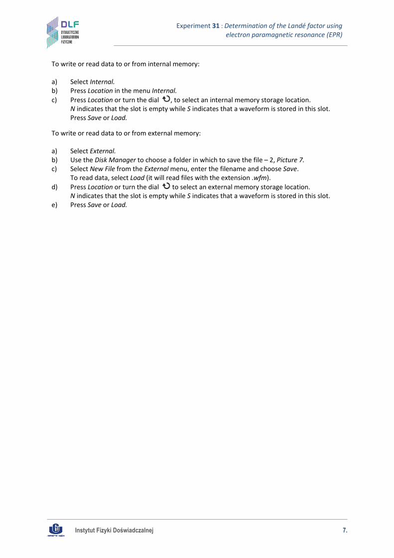
2. Press Save/Recall (2 in Picture 6) on the oscilloscope front panel. 3. Select the internal data format “Waveform” or ASCII (CSV) (1 in Picture 7) by pressing Storage
or turning the dial .
Picture 7. Write/read menu on the oscilloscope front panel: 1 – data type selection button; 2 – memory manager button.
Instytut Fizyki Doświadczalnej 7.
Experiment 31 : Determination of the Landé factor using electron paramagnetic resonance (EPR)
To write or read data to or from internal memory: a) Select Internal. b) Press Location in the menu Internal. c) Press Location or turn the dial , to select an internal memory storage location.
N indicates that the slot is empty while S indicates that a waveform is stored in this slot. Press Save or Load.
To write or read data to or from external memory: a) Select External. b) Use the Disk Manager to choose a folder in which to save the file – 2, Picture 7. c) Select New File from the External menu, enter the filename and choose Save.
To read data, select Load (it will read files with the extension .wfm). d) Press Location or turn the dial to select an external memory storage location.
N indicates that the slot is empty while S indicates that a waveform is stored in this slot. e) Press Save or Load.