Embed Size (px)
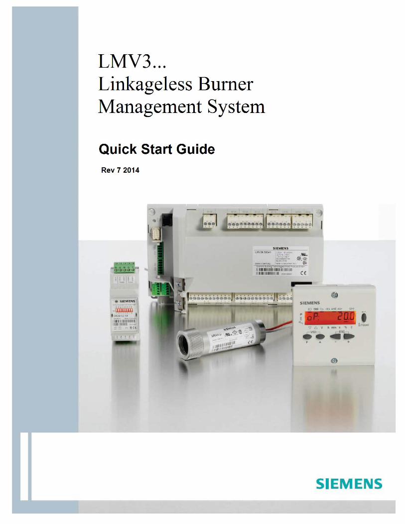
Citation preview

Intentionally Left Blank
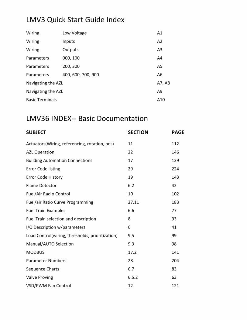
LMV3 Quick Start Guide Index
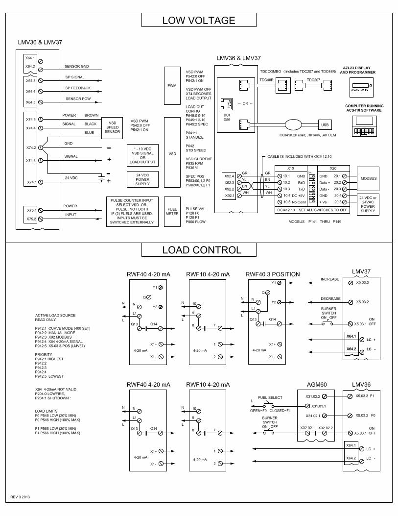
Wiring Low Voltage A1
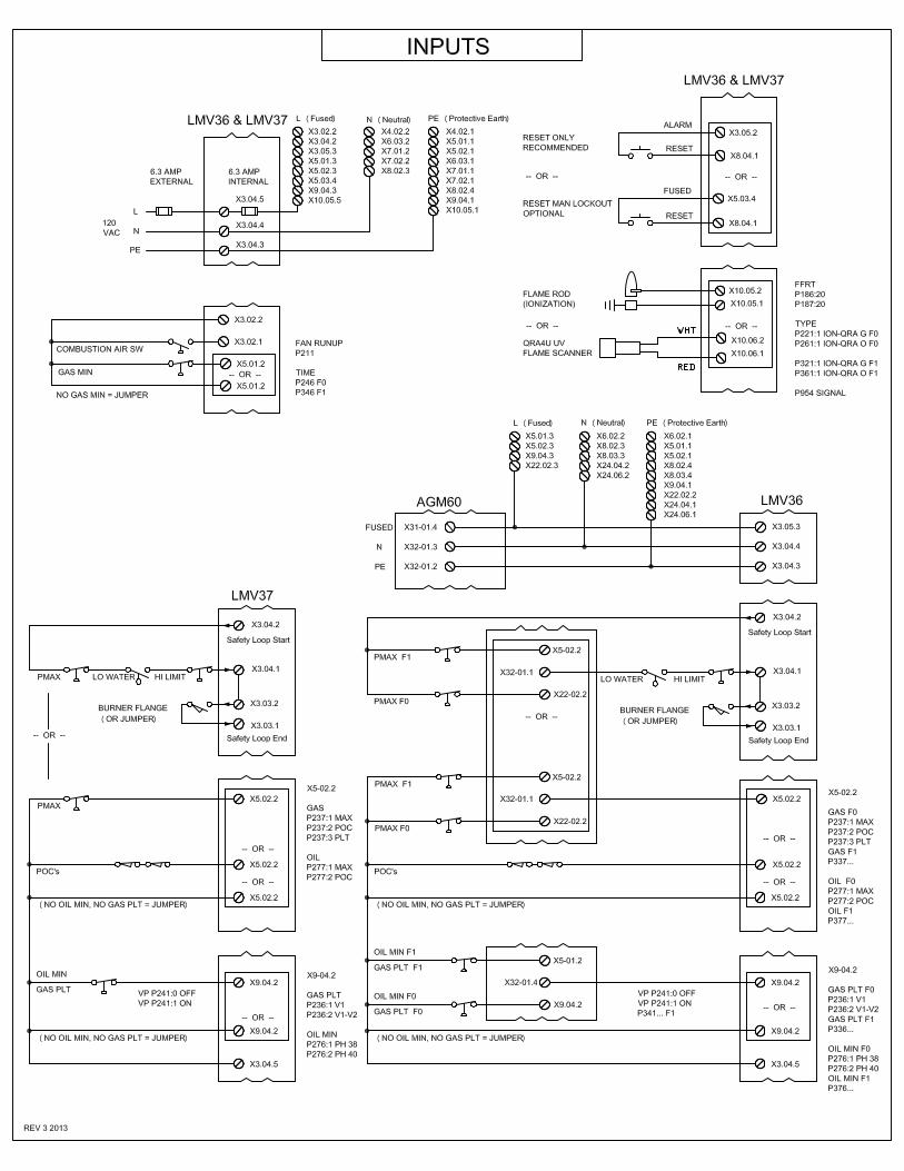
Wiring Inputs A2
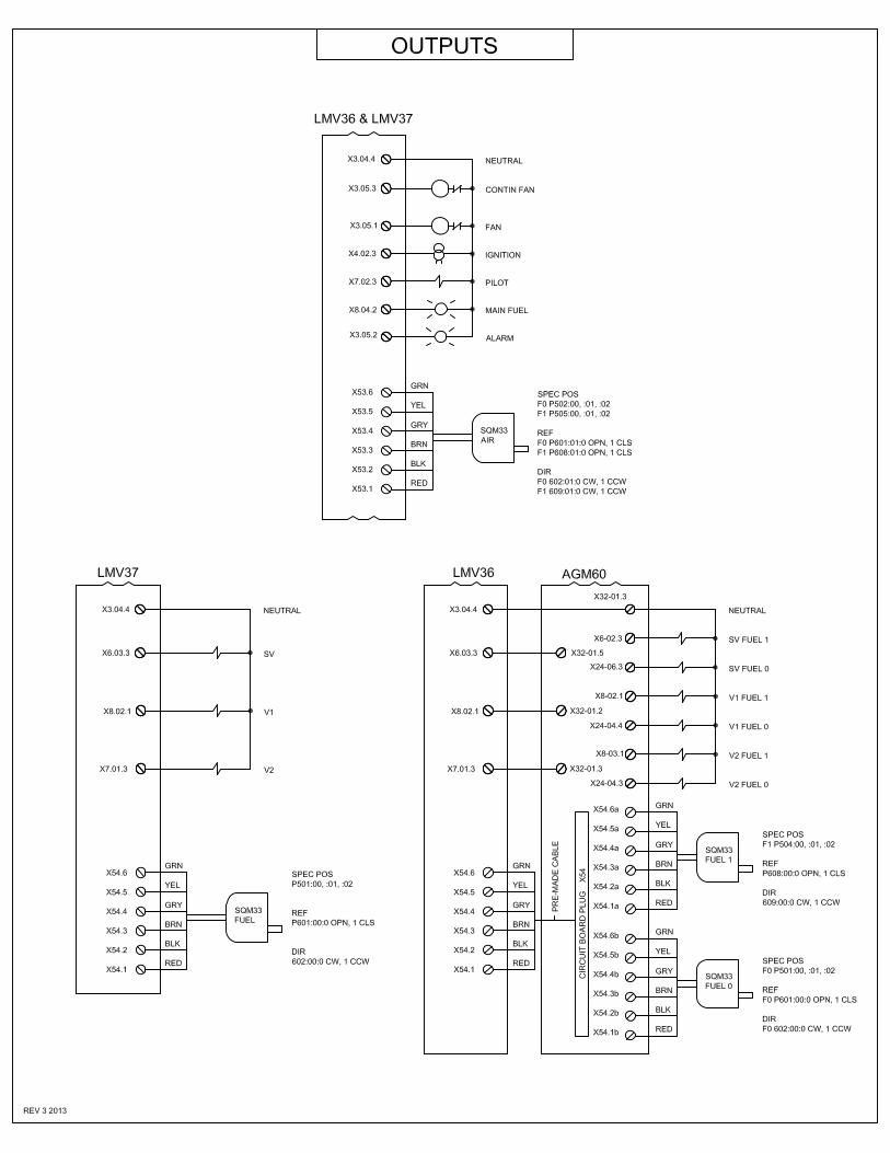
Wiring Outputs A3
Parameters 000, 100 A4
Parameters 200, 300 A5
Parameters 400, 600, 700, 900 A6
Navigating the AZL A7, A8
Navigating the AZL A9
Basic Terminals A10
LMV36 INDEX‐‐ Basic Documentation
SUBJECT SECTION PAGE
Actuators(Wiring, referencing, rotation, pos) 11 112
AZL Operation 22 146
Building Automation Connections 17 139
Error Code listing 29 224
Error Code History 19 143
Flame Detector 6.2 42
Fuel/Air Radio Control 10 102
Fuel/air Ratio Curve Programming 27.11 183
Fuel Train Examples 6.6 77
Fuel Train selection and description 8 93
I/O Description w/parameters 6 41
Load Control(wiring, thresholds, prioritization) 9.5 99
Manual/AUTO Selection 9.3 98
MODBUS 17.2 141
Parameter Numbers 28 204
Sequence Charts 6.7 83
Valve Proving 6.5.2 63
VSD/PWM Fan Control 12 121

Intentionally Left Blank

Intentionally Left Blank
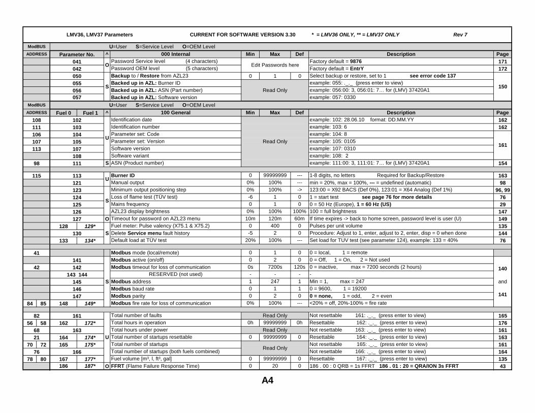
^ 000 Internal Min Max Def Description PagePassword Service level (4 characters) Factory default = 9876 171Password OEM level (5 characters) Factory default = EntrY 172Backup to / Restore from AZL23 0 1 0 Select backup or restore, set to 1 see error code 137Backed up in AZL: Burner ID example: 055: ._._ (press enter to view)Backed up in AZL: ASN (Part number) example: 056:00: 3, 056:01: 7… for (LMV) 37420A1Backed up in AZL: Software version example: 057: 0330
^ 100 General Min Max Def Description PageIdentification date example: 102: 28.06.10 format: DD.MM.YY 162Identification number example: 103: 6 162Parameter set: Code example: 104: 8Parameter set: Version example: 105: 0105Software version example: 107: 0310Software variant example: 108: 2
S ASN (Product number) example: 111:00: 3, 111:01: 7… for (LMV) 37420A1 154
Burner ID 0 99999999 --- 1-8 digits, no letters Required for Backup/Restore 163Manual output 0% 100% --- min = 20%, max = 100%, --- = undefined (automatic) 98Minimum output positioning step 0% 100% -> 123:00 = X92 BACS (Def 0%), 123:01 = X64 Analog (Def 1%) 96, 99
LMV36, LMV37 Parameters CURRENT FOR SOFTWARE VERSION 3.30 * = LMV36 ONLY, ** = LMV37 ONLY Rev 7
ModBUS U=User S=Service Level O=OEM Level ADDRESS
111106107113
98
ModBUS
115
ADDRESS
108
Edit Passwords here
161
O
150Read Only
S
U
U
Fuel 0 Fuel 1
104105107
U=User S=Service Level O=OEM Level
102103
041042050055056057
108111
113
Read Only
121123
Parameter No.
Loss of flame test (TÜV test) -6 1 0 1 = start test see page 76 for more details 76Mains frequency 0 1 0 0 = 50 Hz (Europe), 1 = 60 Hz (US) 29AZL23 display brightness 0% 100% 100% 100 = full brightness 147
O Timeout for password on AZL23 menu 10m 120m 60m If time expires -> back to home screen, password level is user (U) 149Fuel meter: Pulse valency (X75.1 & X75.2) 0 400 0 Pulses per unit volume 135Delete Service menu fault history -5 2 0 Procedure: Adjust to 1, enter, adjust to 2, enter, disp = 0 when done 144Default load at TÜV test 20% 100% --- Set load for TUV test (see parameter 124), example: 133 = 40% 76
Modbus mode (local/remote) 0 1 0 0 = local, 1 = remote Modbus active (on/off) 0 2 0 0 = Off, 1 = On, 2 = Not usedModbus timeout for loss of communication 0s 7200s 120s 0 = inactive, max = 7200 seconds (2 hours)
RESERVED (not used) - - - -Modbus address 1 247 1 Min = 1, max = 247Modbus baud rate 0 1 1 0 = 9600, 1 = 19200Modbus parity 0 2 0 0 = none, 1 = odd, 2 = even
84 85 Modbus fire rate for loss of communication 0% 100% --- <20% = off, 20%-100% = fire rate
Total number of faults Not resettable 161: ._._ (press enter to view) 165
56 58 Total hours in operation 0h 99999999 0h Resettable 162: ._._ (press enter to view) 176Total hours under power Not resettable 163: ._._ (press enter to view) 161Total number of startups resettable 0 99999999 0 Resettable 164: ._._ (press enter to view) 163
70 72 Total number of startups Not resettable 165: ._._ (press enter to view) 161Total number of startups (both fuels combined) Not resettable 166: ._._ (press enter to view) 164
78 80 Fuel volume [m³, l, ft³, gal] 0 99999999 0 Resettable 167: ._._ (press enter to view) 135O FFRT (Flame Failure Response Time) 0 20 0 186 . 00 : 0 QRB = 1s FFRT 186 . 01 : 20 = QRA/ION 3s FFRT 43
76
143 144
41
82
6821
42 140
and
141
149*
U
S
142
145
164
148
174*
128 129*
133 134*130
141
175*
162
S
163
165
172*161
166
187*167 177*
S
146
Read Only
127
125
Read Only
126
124
Read Only
186
147
A4
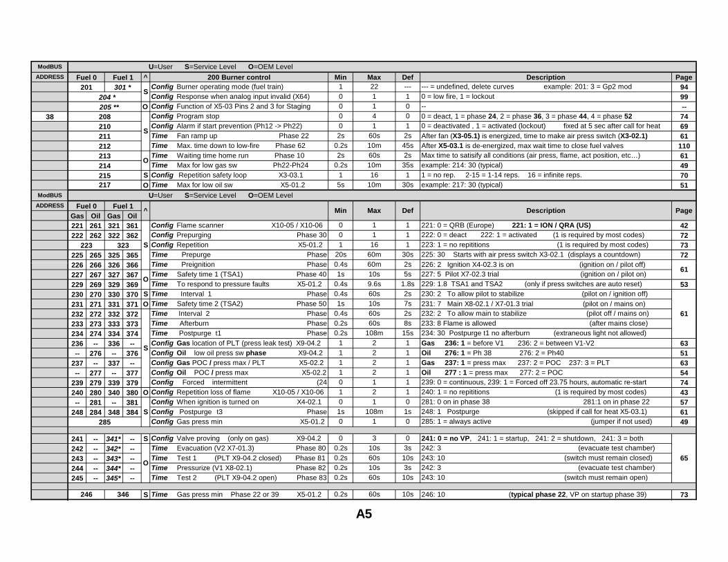
^ 200 Burner control Min Max Def Description PageConfig Burner operating mode (fuel train) 1 22 --- --- = undefined, delete curves example: 201: 3 = Gp2 mod 94Config Response when analog input invalid (X64) 0 1 1 0 = low fire, 1 = lockout 99
O Config Function of X5-03 Pins 2 and 3 for Staging 0 1 0 -- --Config Program stop 0 4 0 0 = deact, 1 = phase 24, 2 = phase 36, 3 = phase 44, 4 = phase 52 74Config Alarm if start prevention (Ph12 -> Ph22) 0 1 1 0 = deactivated , 1 = activated (lockout) fixed at 5 sec after call for heat 69Time Fan ramp up Phase 22 2s 60s 2s After fan (X3-05.1) is energized, time to make air press switch (X3-02.1) 61Time Max. time down to low-fire Phase 62 0.2s 10m 45s After X5-03.1 is de-energized, max wait time to close fuel valves 110Time Waiting time home run Phase 10 2s 60s 2s Max time to satisify all conditions (air press, flame, act position, etc…) 61Time Max for low gas sw Ph22-Ph24 0.2s 10m 35s example: 214: 30 (typical) 49
S Config Repetition safety loop X3-03.1 1 16 1 1 = no rep. 2-15 = 1-14 reps. 16 = infinite reps. 70O Time Max for low oil sw X5-01.2 5s 10m 30s example: 217: 30 (typical) 51
Gas Oil Gas Oil221 261 321 361 Config Flame scanner X10-05 / X10-06 0 1 1 221: 0 = QRB (Europe) 221: 1 = ION / QRA (US) 42
222 262 322 362 Config Prepurging Phase 30 0 1 1 222: 0 = deact 222: 1 = activated (1 is required by most codes) 72Config Repetition X5-01.2 1 16 1 223: 1 = no repititions (1 is required by most codes) 73
225 265 325 365 Time Prepurge Phase 20s 60m 30s 225: 30 Starts with air press switch X3-02.1 (displays a countdown) 72
226 266 326 366 Ti P i iti Ph 0 4 60 2 226 2 I iti X4 02 3 i (i iti / il t ff)
S
S
ADDRESS
ADDRESS
38
ModBUS
ModBUS
Page
U=User S=Service Level O=OEM Level
Fuel 0
^
208210
215
223 323 S
212211
O
204 *
Fuel 1
Fuel 0
214
201 301 *
Fuel 1Description
U=User S=Service Level O=OEM Level
205 **
217
Min Max Def
213
226 266 326 366 Time Preignition Phase 0.4s 60m 2s 226: 2 Ignition X4-02.3 is on (ignition on / pilot off) 227 267 327 367 Time Safety time 1 (TSA1) Phase 40 1s 10s 5s 227: 5 Pilot X7-02.3 trial (ignition on / pilot on)229 269 329 369 Time To respond to pressure faults X5-01.2 0.4s 9.6s 1.8s 229: 1.8 TSA1 and TSA2 (only if press switches are auto reset) 53
230 270 330 370 S Time Interval 1 Phase 0.4s 60s 2s 230: 2 To allow pilot to stabilize (pilot on / ignition off)231 271 331 371 O Time Safety time 2 (TSA2) Phase 50 1s 10s 7s 231: 7 Main X8-02.1 / X7-01.3 trial (pilot on / mains on)232 272 332 372 Time Interval 2 Phase 0.4s 60s 2s 232: 2 To allow main to stabilize (pilot off / mains on)233 273 333 373 Time Afterburn Phase 0.2s 60s 8s 233: 8 Flame is allowed (after mains close)234 274 334 374 Time Postpurge t1 Phase 0.2s 108m 15s 234: 30 Postpurge t1 no afterburn (extraneous light not allowed)236 -- 336 -- Config Gas location of PLT (press leak test) X9-04.2 1 2 1 Gas 236: 1 = before V1 236: 2 = between V1-V2 63
-- 276 -- 376 Config Oil low oil press sw phase X9-04.2 1 2 1 Oil 276: 1 = Ph 38 276: 2 = Ph40 51
237 -- 337 -- Config Gas POC / press max / PLT X5-02.2 1 2 1 Gas 237: 1 = press max 237: 2 = POC 237: 3 = PLT 63
-- 277 -- 377 Config Oil POC / press max X5-02.2 1 2 1 Oil 277 : 1 = press max 277: 2 = POC 54
239 279 339 379 Config Forced intermittent (24 0 1 1 239: 0 = continuous, 239: 1 = Forced off 23.75 hours, automatic re-start 74
240 280 340 380 O Config Repetition loss of flame X10-05 / X10-06 1 2 1 240: 1 = no repititions (1 is required by most codes) 43
-- 281 -- 381 Config When ignition is turned on X4-02.1 0 1 0 281: 0 on in phase 38 281:1 on in phase 22 57
248 284 348 384 Config Postpurge t3 Phase 1s 108m 1s 248: 1 Postpurge (skipped if call for heat X5-03.1) 61Config Gas press min X5-01.2 0 1 0 285: 1 = always active (jumper if not used) 49
241 -- 341* -- S Config Valve proving (only on gas) X9-04.2 0 3 0 241: 0 = no VP, 241: 1 = startup, 241: 2 = shutdown, 241: 3 = both242 -- 342* -- Time Evacuation (V2 X7-01.3) Phase 80 0.2s 10s 3s 242: 3 (evacuate test chamber)243 -- 343* -- Time Test 1 (PLT X9-04.2 closed) Phase 81 0.2s 60s 10s 243: 10 (switch must remain closed)244 -- 344* -- Time Pressurize (V1 X8-02.1) Phase 82 0.2s 10s 3s 242: 3 (evacuate test chamber)245 -- 345* -- Time Test 2 (PLT X9-04.2 open) Phase 83 0.2s 60s 10s 243: 10 (switch must remain open)
S Time Gas press min Phase 22 or 39 X5-01.2 0.2s 60s 10s 246: 10 (typical phase 22, VP on startup phase 39) 73
65
S
O
S
O
285
246 346
61
61
A5
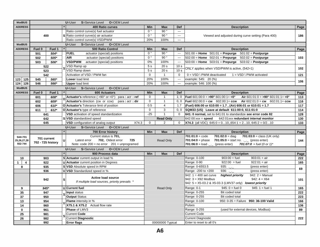
^ 400 Ratio curves Min Max Def Description PageRatio control curve(s) fuel actuator 0 ° 90 ° ---Ratio control curve(s) air actuator 0 ° 90 ° ---Ratio control curve(s) VSD/PWM 20% 100% ---
^ 500 Ratio Control Min Max Def Description PageFUEL actuator (special) positions 0 ° 90 ° --- 501:00 = Home 501:01 = Prepurge 501:02 = PostpurgeAIR actuator (special) positions 0 ° 90 ° --- 502:00 = Home 502:01 = Prepurge 502:02 = PostpurgeVSD/PWM actuator (special) positions 0% 100% --- 503:00 = Home 503:01 = Prepurge 503:02 = PostpurgeVSD Ramp up 5 s 20 s 10 sVSD Ramp down 5 s 20 s 10 sActivation of VSD / PWM fan 0 1 0 0 = VSD \ PWM deactivated 1 = VSD \ PWM activated 121
123 125 Lower load limit 20% 100% --- example: 545: 20 (%)124 126 Upper load limit 20% 100% --- example: 546: 100 (%)
U=User S=Service Level O=OEM Level ^ 600 Actuators Min Max Def Description Page
Actuator's reference ( >90° or <0°) para : act : ref 0 1 1; 0 Fuel 601:00:0 = >90° 601:00:1= <0° Air 601:01:0 = >90° 601:01:1= <0° 113Actuator's direction (cw or ccw) para : act : dir 0 1 0, 0 Fuel 602:00:0 = cw 602:00:1= ccw Air 602:01:0 = cw 602:01:1= ccw 116
O Actuator's Tolerance limit of position 0.5 4 1.7 (Fuel) 606:00 or 610:00 = 1.7 , (Air) 606:01 or 610:01 = 1.7 117O Actuator's type of reference 0 3 0, 0 SQM33 (US) Leave at default 611:00:0, 611:01:0 114
VSD activation of speed standardization -25 1 0 641: 0 normal, set to 641:01 to standardize see error code 82 128
ModBUS
ModBUS
ADDRESS
ModBUS
ADDRESS
ADDRESS
Viewed and adjusted during curve setting (Para 400)S
103501 504*
Fuel 0 Fuel 1
S
566*
502 505*
ONLY applies when VSD/PWM is active, (542=1)
Fuel 0
523
606 610*
Fuel 1
503
608*
565*545
O
400
611 612*
601
522
602 609*
641
546
542
506*
102
186
106
U=User S=Service Level O=OEM Level
U=User S=Service Level O=OEM Level
p ,VSD standardized speed 642:00:xxx = speed 642:01xxx redundant internal monitor 130VSD configuration of analog output X74.3 0 2 0 X74.3 (all VDC) 645:0 = 0...10,,654:1 = 2...10, 645:2 = 0/2...10 133
^ 700 Error history Min Max Def Description Page
U
Current status is 701,Latest error 702, Oldest error 725
Note: code 200 = no error 201 = unprogramed
701:01:0 = code 701:02:0 = diag 701:03:0 = class (UK only)701:04:0 = phase 701:05:0 = start no. ._._ (press enter)701:06:0 = load ._._ (press enter) 701:07:0 = fuel (0 or 1)*
144
^ 900 Process data Min Max Def Description PageS Actuator current output in load % Range: 0-100 903:00 = fuel 903:01 = air 222
1 4 U Actuator current position in Degrees Range: 0-90 922:00 = fuel 922:01 = air 165S VSD Absolute speed in RPM Range: 0-6553.5 935: ._._ (press enter)U VSD Standardized speed in % Range: -200 to +200 936: ._._ (press enter)
SActive load source
If multiple load sources, priority prevails *
942: 1 = 400 set curve highest priority 942: 2 = Manual 942: 3 = X92 Modbus 942: 4 = X64942: 5 = X5-03.2 & X5-03.3 (LMV37 only) lowest priority
101
U Current fuel Range: 0-1 945: 0 = fuel 0 945: 1 = fuel 1 165Input status Range: 0-255 Bit coded total 222Output Status Range: 0-255 Bit coded total 223Flame intensity in % Range: 0-100 950: 0-35 = Failure 950: 36-100 Valid 166X75.1 & X75.2 Actual flow rate Pulses 136Phase of LMV3 Range: 0-255 (used for external devices, Modbus) 89Current Code Current Code Current Diagnostic Current DiagnosticError flags Enter to reset to all 0's
544=70125,26,27,28
552-744
0
10
8
2526
93537
1413
Read Only
U
S
Read Only
S
00000000 Typical982
961
642645
954
936
942
947
S
69
992
701 current702 - 725 history
950
U=User S=Service Level O=OEM Level
222
Read Only
945*
981
903922935
A6
960
U=User S=Service Level O=OEM Level
A6

Intentionally Left Blank
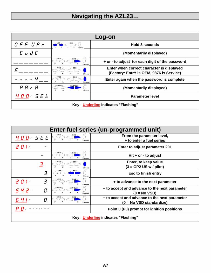
O f f U P r Hold 3 seconds
Log-on
Navigating the AZL23…
O f f U P r Hold 3 seconds
C o d E (Momentarily displayed)
_ _ _ _ _ _ _ + or - to adjust for each digit of the password
E _ _ _ _ _ _ Enter when correct character is displayed(Factory: EntrY is OEM, 9876 is Service)
- - - - Y _ _ Enter again when the password is complete
P A r A (Momentarily displayed)
4 0 0 : S E t Parameter level
Key: Underline indicates "Flashing"
4 0 0 : S E t From the parameter level,+ to enter a fuel series
Enter fuel series (un-programmed unit) 4 0 0 S E t + to enter a fuel series
2 0 1 : - Enter to adjust parameter 201
- Hit + or - to adjust
3 Enter, to keep value(3 = GP2 US w / pilot)
3 E t fi i h t 3 Esc to finish entry
2 0 1 : 3 + to advance to the next parameter
5 4 2 : 0 + to accept and advance to the next parameter(0 = No VSD)
6 4 1 : 0 + to accept and advance to the next parameter(0 = No VSD standardize)(0 No VSD standardize)
P 0 : ---:--- Point 0 (P0) prompt for ignition positions
Key: Underline indicates "Flashing"
A7
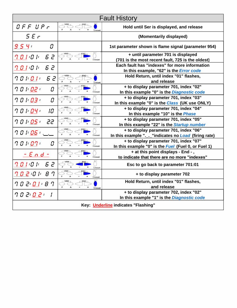
O f f U P r Hold until Ser is displayed, and release
S E r (Momentarily displayed)
9 5 4 : 0 1st parameter shown is flame signal (parameter 954)
Fault History
7 0 1 :0 1: 6 2 + until parameter 701 is displayed(701 is the most recent fault, 725 is the oldest)
7 0 1 :0 1: 6 2 Each fault has "indexes" for more informationIn this example, "62" is the Error code
7 0 1: 0 1 : 6 2 Hold Return, until index "01" flashes, and release
+ to display parameter 701 index "02"7 0 1: 02 : 0 + to display parameter 701, index "02"In this example "0" is the Diagnostic code
7 0 1: 03 : 0 + to display parameter 701, index "03"In this example "0" is the Class (UK use ONLY)
7 0 1: 04 : 10 + to display parameter 701, index "04"In this example "10" is the Phase
7 0 1: 05 : 22 + to display parameter 701, index "05"7 0 1: 05 : 22 p y pIn this example "22" is the Startup number
7 0 1: 06 : ._._ + to display parameter 701, index "06"In this example "._._"indicates no Load (firing rate)
7 0 1: 07 : 0 + to display parameter 701, index "07"In this example "0" is the Fuel (Fuel 0, or Fuel 1)
- E n d - + at this point displays - End - , to indicate that there are no more "indexes"to indicate that there are no more indexes
7 0 1 :0 1: 6 2 Esc to go back to parameter 701:01
7 0 2 :0 1: 8 7 + to display parameter 702
7 0 2: 0 1 : 8 7 Hold Return, until index "01" flashes, and release
7 0 2: 0 2 : 1 + to display parameter 702, index "02"7 0 2: 0 2 : 1 to display parameter 702, index 02In this example "1" is the Diagnostic code
Key: Underline indicates "Flashing"
8/8
Building Technologies Division Benutzerhandbuch AZL2… CC1U7542en Infrastructure & Cities Sector 07.12.2012
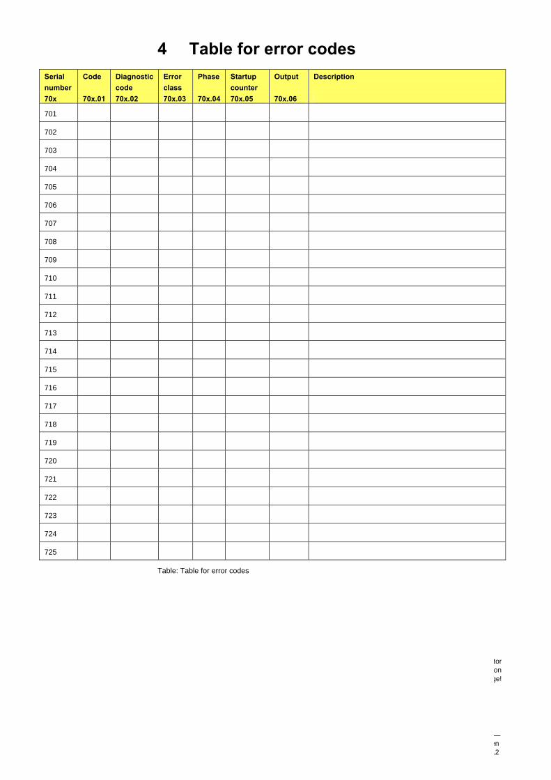
4 Table for error codes
Serial number
Code Diagnostic code
Error class
Phase Startup counter
Output Description
70x 70x.01 70x.02 70x.03 70x.04 70x.05 70x.06
701
702
703
704
705
706
707
708
709
710
711
712
713
714
715
716
717
718
719
720
721
722
723
724
725
Table: Table for error codes
Siemens AG Infrastructure & Cities Sector Building Technologies DivisionBerliner Ring 23 D-76437 Rastatt Tel. +49 7222 598 279 Fax +49 7222 598 269 www.siemens.com
© 2012 Siemens AG Infrastructure & Cities Sector Building Technologies Division
Subject to change!
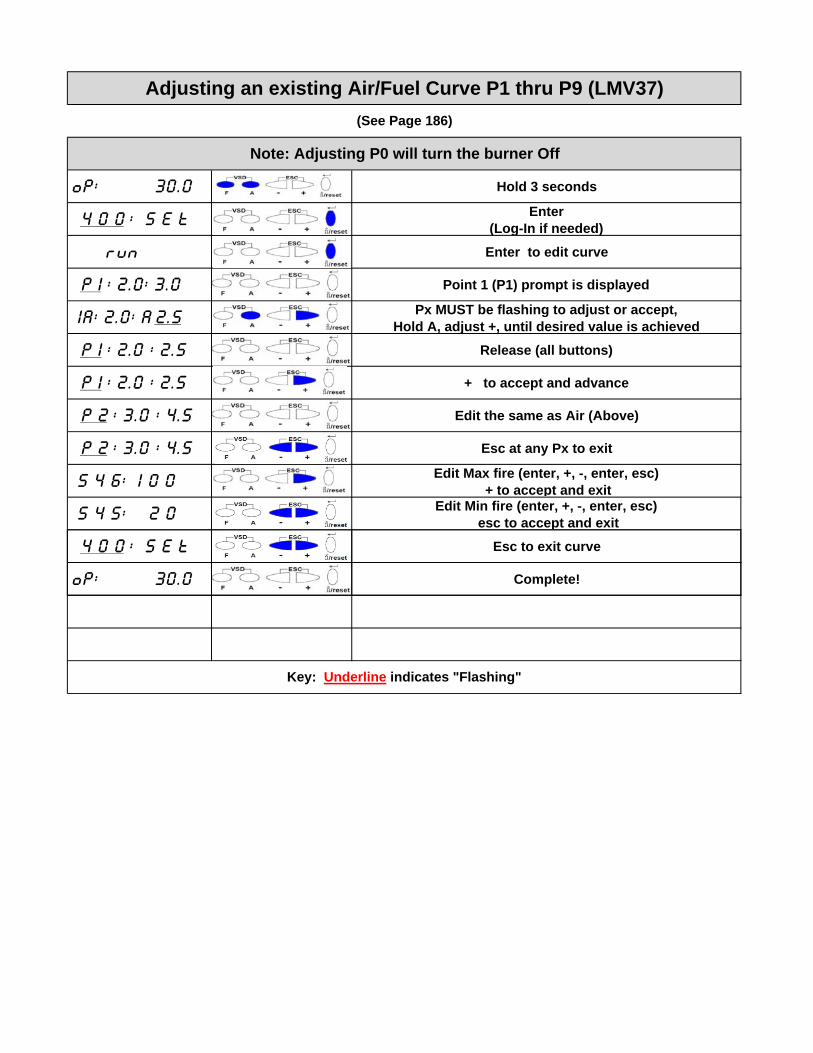
oP: 30.0 Hold 3 seconds
4 0 0 : S E t Enter (Log-In if needed)
run Enter to edit curve
P 1 : 2.0: 3.0 Point 1 (P1) prompt is displayed
1A: 2.0: A 2.5 Px MUST be flashing to adjust or accept,Hold A, adjust +, until desired value is achieved
P 1 : 2.0 : 2.5 Release (all buttons)
P 1 : 2.0 : 2.5 + to accept and advance
P 2 : 3.0 : 4.5 Edit the same as Air (Above)
P 2 : 3.0 : 4.5 Esc at any Px to exit
5 4 6: 1 0 0 Edit Max fire (enter, +, -, enter, esc)+ to accept and exit
5 4 5: 2 0 Edit Min fire (enter, +, -, enter, esc)esc to accept and exit
4 0 0 : S E t Esc to exit curve
Note: Adjusting P0 will turn the burner Off
Adjusting an existing Air/Fuel Curve P1 thru P9 (LMV37)
(See Page 186)
oP: 30.0 Complete!
Key: Underline indicates "Flashing"
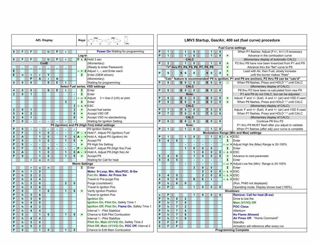
0 F F U P r Power On Waiting for programming P 1 : 1 . 0 : 1 . 0 When P1 flashes: Adjust (F+/-, A+/-) if necessary
P 1 : 1 . 0 : 1 . 0 + Advance in the combustion curve
0 F F U P r F & A Hold 3 sec (Momentary display of automatic CALC)
(Momentary) P 2 : 1 . 0 : 1 . 0 + P2 thru P8 have now been linearized from P1 and P9
_ _ _ _ _ _ _ (Ready to enter Password) + Advance thru the "flat" curve to P9
E - + I Adjust +, -, and Enter each +
E n t r Y I Enter (OEM shown) +
P A r A (Momentary)
4 0 0 : S E t Waiting for programming P 9 : 9 0 . 0 : 9 0 . 0 - When P9 flashes, Press and HOLD "-" until CALC
(Momentary display of CALC)
4 0 0 : S E t I Enter P 8 : 8 5 . 0 : 8 5 . 0 P8 thru P2 have been re-calculated from new P9
2 0 1 : - I Enter P1 and P9 do not CALC, but can be adjusted
- - or + Adjust 3 = Gas 2 (US) w/ pilot P 8 : 8 5 . 0 : 8 5 . 0 + Adjust: F and +/- (fuel) A and +/- (air) and VSD if used
3 I Enter P 8 : 8 0 . 0 : 8 0 . 0 + When P8 flashes, Press and HOLD "-" until CALC
3 - & + ESC (Momentary display of CALC)
2 0 1 : 3 + Accept fuel series P 7 : 7 5 . 0 : 7 5 . 0 Adjust: F and +/- (fuel) A and +/- (air) and VSD if used
5 4 2 : 0 + Accept VSD Off P 7 : 7 0 . 0 : 7 0 . 0 When P7 flashes, Press and HOLD "-" until CALC
6 4 1 : 0 + Accept VSD no standardizing (Momentary display of CALC)
P 0 : - - - : - - - Waiting for Ignition Setting P 6 : 6 0 . 0 : 6 0 . 0 Continue P6 thru P2
P1 thru P9 MUST flash after you adjust to validate
P 0 : - - - : - - - P0 Ignition Setting P 1 : 1 . 0 : 1 . 0 When P1 flashes (after adj) your curve is complete
0 F : 1 . 0 : - - - F - + Hold F, Adjust P0 (Ignition) Fuel
0 A : 1 . 0 : 1 . 0 A - + Hold A, Adjust P0 (Ignition) Air P 1 : 1 . 0 : 1 . 0 - & + ESC
P 0 : 1 . 0 : 1 . 0 + Accept P0 5 4 6 : - - - - I Enter
P 9 : - - - : - - - + P9 High fire Setting - - - - - or + Adjust High fire (Max) Range is 20-100%
9 F : 1 . 0 : - - - F - + Hold F, Adjust P9 (High fire) Fuel 1 0 0 . 0 I Enter
9 A : 1 . 0 : 1 . 0 A - + Hold A, Adjust P9 (High fire) Air 1 0 0 . 0 - & + ESC
P 9 : 1 . 0 : 1 . 0 + Accept P9 5 4 6 : 1 0 0 . 0 + Advance to next parameter
r u n Waiting for Call for heat 5 4 5 : - - - - I Enter
- - - - - or + Adjust Low fire (Min) Range is 20-100%
r u n I Enter 2 0 . 0 I Enter
P h 1 2 Make: S-Loop, Min, Max/POC, B-Sw 2 0 . 0 - & + ESC
P h 2 2 Fan On, Make: Air Press Sw 5 4 5 : 2 0 . 0 - & + ESC
P h 2 4 Travel to Pre-purge Pos 4 0 0 : S E t - & + ESC
P h 3 0 2 0 Purge (countdown) P h 6 0 (Run, Ph60 not displayed)
P h 3 6 Travel to Ignition Pos o P : 1 0 0 . 0 Operating mode, Display shows load (100%)
P 0 : 1 . 0 : 1 . 0 + Verify Ignition Position
P h 3 6 Travel to Ignition Pos o P : 1 0 0 . 0 Remove: Call for heat (B-sw)
P h 3 8 Ignition On P h 6 2 Drive to low fire
P h 4 0 Ignition On, Pilot On, Safety Time 1 P h 7 0 Main (V1/V2) Off
P h 4 2 Ignition Off, Pilot On, Flame On, Safety Time 1 P h 7 2 POC Close
P h 4 4 Interval 1 - Pilot Stabilize P h 7 4 Afterburn
P 0 : 1 . 0 : 1 . 0 + Chance to Edit Pilot Combustion P h 7 8 No Flame Allowed
P h 4 4 Interval 1 - Pilot Stabilize P h 1 0 Air Press Off "Home Command"
P h 5 0 Pilot On, Main (V1/V2) On, Safety Time 2 0 F F Standby
P h 5 2 Pilot Off, Main (V1/V2) On, POC Off, Interval 2 0 F F Actuators will reference after every run
P 0 : 1 . 0 : 1 . 0 Chance to Edit Main Combustion
LMV3 Startup, Gas/Air, 400 set (fuel curve) procedure
Select Fuel series, VSD settings
P0 (Ignition) and P9 (High Fire) Initial settings
Warm Settings
AZL Display Keys
Log-In
CodE
"+" thru P3, P4, P5, P6, P7, P8, P9
CALC
0 0
CALC
Note:
Fuel Curve settings
CALC
9
Programming Complete
Shutdown
Modulation Range (Min and Max) settings
Lead with Air, then Fuel, slowly increase
until the burner makes "Rate".
CALC
Note:
0 0
"Calc" feature is recommended! P0 is ignition, P1 and P9 are anchors, P2 thru P8 can be "calc'd"
. : 9: 9P
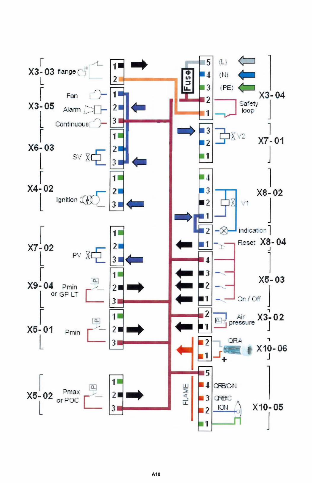
A10
Software version V03.30 CC1P7544en 15.10.2010 Building Technologies Division
Industry Sector
LMV36... AGM60...
LMV36.520A1 / AGM60.4A9 Basic unit with integrated fuel-air ratio control for forced draft burners Basic Documentation
The LMV36... / AGM60... and this Basic Documentation are intended for OEMs which integrate the units in their products!

2/242
Building Technologies Division Basic Documentation LMV36... CC1P7544en Industry Sector 15.10.2010
3/242
Building Technologies Division Basic Documentation LMV36... CC1P7544en Industry Sector 15.10.2010
Supplementary documentation User Documentation Modbus AZL2... .....................................................................A7541
Environmental Product Declaration LMV2… / LMV3...............................................E7541
Installation and Operating Instructions PC Software ACS410................................. J7352
Product Range Overview LMV2… / LMV3... .......................................................... Q7541

4/242
Building Technologies Division Basic Documentation LMV36... CC1P7544en Industry Sector 15.10.2010
5/242
Building Technologies Division Basic Documentation LMV36... CC1P7544en Industry Sector Contents 15.10.2010
Contents 1 Safety notes .................................................................................................13 1.1 Warning notes ...............................................................................................13 1.2 Mounting notes ..............................................................................................15 1.2.1 LMV36... ........................................................................................................15
− Notes on mounting ............................................................................15 1.2.2 AGM60... .......................................................................................................16
− Notes for mounting............................................................................16 − Mounting method ..............................................................................16
1.3 Installation notes............................................................................................17 1.3.1 Use of the AGM60... ......................................................................................18 1.4 Electrical connections of LMV36... and AGM60... .........................................18 1.4.1 LMV36... ........................................................................................................18 1.4.2 AGM60... .......................................................................................................19 1.5 Electrical connection of flame detectors ........................................................19 1.6 Commissioning notes ....................................................................................20
− Fuel-air ratio control system.............................................................20 − Basic unit section ..............................................................................20
1.7 Notes on settings and parameter settings .....................................................22 1.8 Standards and certificates .............................................................................23 1.9 Service notes.................................................................................................23 1.10 Life cycle........................................................................................................23
− LMV36... ............................................................................................23 − AGM60... ...........................................................................................23 − General .............................................................................................23
1.11 Disposal notes ...............................................................................................23
2 Makeup of structure / function description...............................................24 2.1 LMV36... ........................................................................................................24 2.2 For North American .......................................................................................24 2.3 General information .......................................................................................25 2.4 AGM60... .......................................................................................................26 2.4.1 Electrical connections of fuel actuators .........................................................26 2.4.2 Continuous operation ....................................................................................27 2.4.3 Fuel changeover............................................................................................27 2.4.4 Extra fuel selector..........................................................................................27
3 Type summary .............................................................................................28 3.1 LMV36... ........................................................................................................28 3.2 AGM60... .......................................................................................................28 3.3 Fuel selector ..................................................................................................28
4 Technical data..............................................................................................29 4.1 LMV36... basic unit ........................................................................................29 4.1.1 Terminal loading Inputs .................................................................................29 4.1.2 Terminal loading Outputs ..............................................................................30 4.1.3 Analog output / load output X74.3 .................................................................30 4.1.4 Cable lengths.................................................................................................31
6/242
Building Technologies Division Basic Documentation LMV36... CC1P7544en Industry Sector Contents 15.10.2010
4.1.5 Cross-sectional areas ....................................................................................31 4.2 Signal cable AGV50... from AZL2... → BCI ...................................................32 4.3 Environmental conditions...............................................................................32 4.4 Flame detectors .............................................................................................33 4.4.1 Ionization probe .............................................................................................33 4.4.2 UV flame detectors QRA2… / QRA4.U / QRA10… .......................................34 4.4.3 Photoresistive flame detectors QRB… ..........................................................35 4.5 Switch unit AGM60... .....................................................................................36 4.5.1 Terminal output Inputs ...................................................................................37 4.5.2 Terminal output Outputs ................................................................................37 4.5.3 Cable lengths .................................................................................................38 4.5.4 Cross-sectional areas ....................................................................................38 4.5.5 Electrical connections of actuators ................................................................38 4.5.6 Environmental conditions...............................................................................38
5 Dimensions...................................................................................................39 5.1 LMV36............................................................................................................39 5.2 AGM60...........................................................................................................40
6 Basic unit......................................................................................................41 6.1 Description of inputs and outputs...................................................................41
− Flame signal input and flame detector X10–05 and X10–06 ................41 6.2 Flame detectors .............................................................................................42 6.2.1 Loss of flame..................................................................................................43 6.2.2 Extraneous light .............................................................................................43 6.2.3 No flame at the end of safety time (TSA).......................................................43 6.2.4 Flame intensity...............................................................................................44 6.2.5 Supervision of flame detector ........................................................................44 6.3 Digital inputs ..................................................................................................45 6.3.1 Safety loop X3–04 (optional pressure switch-max (Pmax)), terminals 1
and 2 ..............................................................................................................45 6.3.2 (Burner flange) X3–03, terminals 1 and 2 ......................................................46 6.3.3 Input for external controller (ON / OFF) X5–03, terminal 1 ............................46 6.3.4 Air pressure switch (APS) X3–02...................................................................47 6.3.5 Pressure switch for gas valve proving (P LT) X9-04......................................48 6.3.6 Gas pressure switch-min (Pmin), start release gas X5–01............................49 6.3.7 Oil pressure switch-min (Pmin) X9-04 (X5–01 on AGM60...) ........................50 6.3.8 Setting the time for checking the pressure switch..........................................51 6.3.9 Gas / oil pressure switch-max (Pmax) / or POC contact, start release
oil X5–02 ........................................................................................................52 6.3.10 Fuel selection.................................................................................................55 6.3.11 Reset X8-04, terminal 1 .................................................................................55 6.4 Digital outputs ................................................................................................56 6.4.1 Output alarm type No-SI X3–05, terminal 2 ...................................................56 6.4.2 Fan motor contactor type SI X3–05, terminal 1 .............................................56 6.4.3 Fan continuous purging X3–05, terminal 3 ....................................................56 6.4.4 Output ignition (Z) type SI (IGNITION) X4–02 ...............................................57 6.4.5 Outputs fuel valves type SI (V1...V3 / PV) X8–02, X7-01, X7-02...................58 6.4.6 Output safety valve (SV) type SI X6–03 / magnetic clutch ............................60
7/242
Building Technologies Division Basic Documentation LMV36... CC1P7544en Industry Sector Contents 15.10.2010
6.4.7 Output for indication of operation X8-04 terminal 2 .......................................60 6.5 Program sequence ........................................................................................61 6.5.1 Time parameters ...........................................................................................61 6.5.2 Valve proving.................................................................................................63 6.5.3 Valve proving with separate pressure switch (P LT) X9-04...........................64 6.5.4 Valve proving via gas pressure switch-min X5-01.........................................65 6.5.4.1. Lockout phase (phase 00) .............................................................................65 6.5.4.2. Safety phase (phase 02) ...............................................................................66 6.5.5 Special functions during the program sequence ...........................................67 6.5.5.1. Reset / manual lockout ..................................................................................67 6.5.5.2. Alarm upon prevention of startup ..................................................................69 6.5.5.3. Possible preventions of startup .....................................................................69 6.5.5.4. Repetition counter .........................................................................................70 6.5.5.5. Start without prepurging (as per EN 676) ......................................................72 6.5.5.6. Gas shortage program...................................................................................73 6.5.5.7. Program stop function ...................................................................................74 6.5.5.8. Forced intermittent operation (<24 hours) .....................................................74 6.5.5.9. Low-fire shutdown .........................................................................................74 6.5.5.10. Continuous fan ..............................................................................................75 6.5.5.11. Test function for burner approval – loss-of-flame test (TÜV test)..................76 6.6 Fuel trains (application examples).................................................................77
− Gas direct ignition .............................................................................77 − (Operating mode 1, 7, 14, 19) ...........................................................77 − Gas pilot ignition 1.............................................................................77 − (Operating mode 2, 8, 15, 20) ...........................................................77 − Gas pilot ignition 2.............................................................................77 − (Operating mode 3, 9, 16, 21) ...........................................................77 − Fuel valve control program................................................................77 − Light oil direct ignition, multistage .....................................................78 − (Operating mode 5, 17) .....................................................................78 − (Operating mode 5, 17) .....................................................................78 − (Operating mode 6, 18) .....................................................................78 − Light oil direct ignition, modulating ....................................................79 − (Operating mode 4, 22) .....................................................................79 − (Operating mode 4, 22) .....................................................................79 − Fuel valve control program................................................................79 − Dual fuel burner gas/ light oil with gas pilot ignition (Operating mode
3, 9, 16, 21) (Operating mode 10, 11)..................................80 − Fuel valve control program................................................................80 − Light oil direct ignition modulating with 2 fuel valves.........................81 − (Operating mode 12) .........................................................................81 − (Operating mode 12) .........................................................................81 − Fuel valve control program................................................................81 − Dual fuel burner gas / light oil with gas pilot ignition with 2 fuel valves
(Operating mode 3, 9, 16, 21) (Operating mode 13).............82 − Fuel valve control program................................................................82
6.7 Sequence diagrams.......................................................................................83 6.7.1 Gas direct ignition «G», «G mod», «G mod pneu» .......................................84 6.7.2 Gas pilot ignition 1 «Gp1», «Gp1 mod», «Gp1 mod pneu»...........................85 6.7.3 Gas pilot ignition 2 «Gp2», «Gp2 mod», «Gp2 mod pneu»...........................86 6.7.4 Light oil direct ignition «Lo», «Lo mod», «Lo 2-stage», «Lo 3-stage» ...........87
8/242
Building Technologies Division Basic Documentation LMV36... CC1P7544en Industry Sector Contents 15.10.2010
6.7.5 Light oil pilot ignition «Lo Gp»........................................................................88 6.7.6 Legend to sequence diagrams.......................................................................89 6.7.7 Legend to the sequence diagrams.................................................................89
7 AGM60...........................................................................................................91 7.1 System with AGM60... and one fuel actuator.................................................91 7.2 System with AGM60... and two fuel actuators ...............................................91 7.3 Connecting cable between AGM60... and LMV36... basic unit (AGV61.100
cable) .............................................................................................................92
8 Selection of operating mode.......................................................................93 8.1 Deleting curves ..............................................................................................95
9 Connection to load controllers...................................................................96 9.1 Controller-on contact X5-03, terminal 1 .........................................................96 9.2 Load controller via BAC system X92 .............................................................96 9.3 Manual output ................................................................................................98 9.4 Output with curve settings..............................................................................98 9.5 External load controller via analog input X64.1 / X64.2 .................................99
− Switching thresholds / minimum positioning step..................................99 9.5.1 Thresholds for modulating operation .............................................................99 9.5.2 Switching thresholds for multistage operation .............................................100 9.6 Prioritization of power sources.....................................................................101 9.6.1 Emergency operation with several load controllers .....................................101
10 Electronic fuel-air ratio control.................................................................102 10.1 General ........................................................................................................102 10.2 Behavior outside the operating positions .....................................................102 10.2.1 Traveling speed ...........................................................................................102 10.2.2 Home position ..............................................................................................102 10.2.3 Prepurging ...................................................................................................103 10.2.4 Ignition .........................................................................................................103 10.2.5 Postpurging..................................................................................................103 10.3 Modulating operation ...................................................................................104 10.3.1 Definition of curves ......................................................................................104 10.3.2 Traveling speed/maximum curve slope .......................................................105 10.3.3 Entering the running position .......................................................................105 10.3.4 Operating position........................................................................................105 10.3.5 Limitation of modulation range.....................................................................106 10.3.6 Setting the minimum and maximum output..................................................107 10.4 Multistage operation.....................................................................................108 10.4.1 Definition of curves ......................................................................................108 10.4.2 Traveling speed ...........................................................................................108 10.4.3 Adjustment of output ....................................................................................109 10.4.4 Entering the operating position ....................................................................109 10.4.5 Operating position........................................................................................109 10.4.6 Limitation of modulation range.....................................................................110 10.5 End of operating position .............................................................................110 10.6 Notes on settings and parameter settings ...................................................111
9/242
Building Technologies Division Basic Documentation LMV36... CC1P7544en Industry Sector Contents 15.10.2010
11 Actuators X53 / X54 ...................................................................................112 11.1 Function principle ........................................................................................112 11.2 Definition of angles ......................................................................................112 11.3 Referencing .................................................................................................113 11.3.1 Reference run..............................................................................................114
− Reference travel type 1 ...................................................................114 − Reference travel type 2 ...................................................................114
11.4 Direction of rotation .....................................................................................116 11.5 Monitoring the actuator positions.................................................................117 11.6 Changing the error detection band for monitoring the actuator positions....119 11.7 Forced travel................................................................................................119 11.8 Detection of line interruptions ......................................................................119 11.9 Protection against mixup of actuators .........................................................120 11.9.1 Proposal for implementation........................................................................120
12 Fan control .................................................................................................121 12.1 Function principle ........................................................................................121 12.2 Activation of VSD/PWM fan.........................................................................121 12.3 VSD control X74.3 .......................................................................................122 12.4 PWM fan control X64.3................................................................................123 12.5 Safe separation of mains voltage and protective extra low-voltage ............123 12.6 Ramp time ...................................................................................................123
− For VSD operation ..............................................................................123 12.7 Acquisition of speed ....................................................................................124 12.7.1 Acquisition of speed with proximity switch...................................................124
− Speed input X74.4 ..............................................................................124 12.7.2 Acquisition of speed with Hall generator .....................................................125 12.8 Speed control ..............................................................................................126 12.9 Speed supervision .......................................................................................126 12.10 Setting the parameters of the VSD..............................................................127 12.11 Standardization of speed.............................................................................128
− Automatic speed standardization........................................................128 12.12 Control of fan motor with pneumatic fuel-air ratio control ............................130 12.13 EMC of LMV36... and VSD..........................................................................131 12.14 Description of connection terminals.............................................................132 12.14.1 VSD .............................................................................................................132 12.14.2 PWM fan......................................................................................................132
13 Load output X74.3 .....................................................................................133 13.1 Safe separation of mains voltage and extra low-voltage ............................133 13.2 Modulating operation ...................................................................................133 13.3 2-stage operation.........................................................................................133 13.4 3-stage operation.........................................................................................134
14 Fuel meter input X75.1 / X75.2..................................................................135 14.1 Configuration of fuel meter ..........................................................................135 14.1.1 Types of fuel meters ....................................................................................135
10/242
Building Technologies Division Basic Documentation LMV36... CC1P7544en Industry Sector Contents 15.10.2010
14.1.2 Configuration of pulses per volume unit.......................................................135 14.1.3 Reading and resetting the meter readings...................................................135 14.2 Fuel throughput............................................................................................136 14.2.1 Configuration................................................................................................136 14.2.2 Reading out the fuel throughput...................................................................136
15 Connection and internal diagram.............................................................137
16 Special feature: Burner identification (ID) ...............................................139
17 Connection to superposed systems ........................................................139 17.1 General information and building automation functions...............................139 17.2 Modbus ........................................................................................................141
18 PC software ACS410..................................................................................142
19 Error history ...............................................................................................143 19.1 Error classes ................................................................................................143 19.2 Makeup of error history ................................................................................144
− Deleting the error history .................................................................144
20 Lifecycle function ......................................................................................145
21 Safety notes on use of the AZL2... ...........................................................145
22 Operating the AZL2... unit .........................................................................146 22.1 Description of unit/display and buttons ........................................................146 22.2 Meaning of symbols on the display..............................................................147 22.3 Brightness of display....................................................................................147 22.4 Special functions..........................................................................................148 22.4.1 Manual lockout.............................................................................................148 22.4.2 Manual control (manual request for output) .................................................148 22.5 Timeout for menu operation.........................................................................149 22.6 Backup / restore...........................................................................................150 22.6.1 Backup .........................................................................................................151 22.6.2 Restore ........................................................................................................153
23 Operation of basic unit via the AZL2... ....................................................155 23.1 Normal display .............................................................................................155 23.1.1 Display in standby mode..............................................................................155 23.1.2 Display during startup / shutdown................................................................155 23.1.2.1. Display of program phases ..........................................................................155 23.1.2.2. Display of program phase with remaining running time until end of the
phase is reached..........................................................................................155 23.1.2.3. List of phase displays...................................................................................156 23.1.3 Display of operating position........................................................................156 23.1.4 Fault status messages, display of errors and info........................................157 23.1.4.1. Display of errors (faults) with lockout ...........................................................157 23.1.4.2. Reset............................................................................................................157 23.1.4.3. Activating info / service mode from lockout..................................................157 23.1.4.4. Error with safety shutdown...........................................................................158 23.1.4.5. General information .....................................................................................158
11/242
Building Technologies Division Basic Documentation LMV36... CC1P7544en Industry Sector Contents 15.10.2010
23.1.4.6. Prevention of startup ...................................................................................158 23.1.4.7. Safety loop...................................................................................................158
24 Menu-driven operation..............................................................................159 24.1 Assignment of levels....................................................................................159
25 Info level .....................................................................................................160 25.1 Display of info level......................................................................................162 25.2 Display of info values (examples)................................................................162 25.2.1 Identification date ........................................................................................162 25.2.2 Identification number ...................................................................................162 25.2.3 Burner identification.....................................................................................163 25.2.4 Number of startups resettable .....................................................................163 25.2.5 Total number of startups..............................................................................164 25.2.6 End of info level ...........................................................................................164
26 Service level...............................................................................................165 26.1 Display of service level ................................................................................165 26.2 Display of service values (example) ............................................................166 26.2.1 Number of faults ..........................................................................................166 26.2.2 Error history .................................................................................................166 26.2.3 Intensity of flame .........................................................................................166 26.2.4 End of service level .....................................................................................166
27 Parameter level ..........................................................................................167 27.1 Entry of password........................................................................................168 27.2 Entry of burner identification........................................................................170 27.3 Change of heating engineer’s password .....................................................171 27.4 Change of OEM’s password........................................................................172 27.5 Use of parameter level ................................................................................172 27.6 Structure of parameter levels ......................................................................173 27.7 Parameters without index, with direct display..............................................174 27.7.1 Using the example of parameter 208: Program stop...................................174 27.8 Parameters without index, with no direct display (with parameters having a
value range >5 digits) ..................................................................................176 27.8.1 Using the example of parameter 162: Operating hours resettable..............176 27.9 Parameter with index, with direct display ....................................................178 27.9.1 Using the example of parameter 501: No-flame positions fuel actuator......178 27.10 Parameters with index, with no direct display..............................................180 27.10.1 Using the example of parameter 701: Errors...............................................180 27.11 Fuel-air ratio curves – settings and commissioning.....................................183 27.11.1 Initial commissioning ...................................................................................183 27.11.2 Setting curvepoints P0 and P9 for modulating operation («G mod»,
«Gp1 mod», «Gp2 mod» and «Lo mod»)....................................................186 27.11.3 Setting curvepoints P0 and P9 for «G mod pneu», «Gp1 mod pneu»
and «Gp2 mod pneu»..................................................................................187 27.11.4 Warm settings for modulating operation («G mod», «Gp1 mod», «Gp2
mod» and «Lo mod») ..................................................................................188
12/242
Building Technologies Division Basic Documentation LMV36... CC1P7544en Industry Sector Contents 15.10.2010
27.11.5 Warm settings for modulating mode («G mod pneu», «Gp1 mod pneu» and «Gp2 mod pneu») .................................................................................193
27.11.6 Cold settings for «G mod», «Gp1 mod», «Gp2 mod» and «Lo mod»..........193 27.11.7 Cold settings for «G mod pneu», «Gp1 mod pneu» and «Gp2 mod
pneu» ...........................................................................................................193 27.11.8 Interpolation of curvepoints..........................................................................194 27.11.9 Interpolating the curvepoints........................................................................195 27.11.10 Setting of curvepoints for multistage mode («Lo 2-stage» and «Lo 3-
stage») .........................................................................................................198 27.11.11 Warm settings for «Lo 2-stage» and «Lo 3-stage»......................................199 27.11.12 Cold settings for multistage mode («Lo 2-stage» and «Lo 3-stage») ..........203 27.11.13 Intensity of flame during curve settings........................................................203
28 Parameter list LMV36.................................................................................204
29 Error code list.............................................................................................224
30 Revision history of basic unit LMV36... ...................................................239 − Software changes ...............................................................................239
31 List of figures .............................................................................................240
13/242
Building Technologies Division Basic documentation LMV36... CC1P7544en Industry Sector 1 Safety notes 15.10.2010
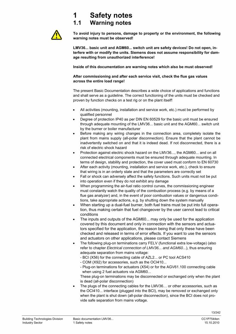
1 Safety notes 1.1 Warning notes To avoid injury to persons, damage to property or the environment, the following warning notes must be observed! LMV36... basic unit and AGM60... switch unit are safety devices! Do not open, in-terfere with or modify the units. Siemens does not assume responsibility for dam-age resulting from unauthorized interference! Inside of this documentation are warning notes which also be must observed! After commissioning and after each service visit, check the flue gas values across the entire load range! The present Basic Documentation describes a wide choice of applications and functions and shall serve as a guideline. The correct functioning of the units must be checked and proven by function checks on a test rig or on the plant itself! • All activities (mounting, installation and service work, etc.) must be performed by
qualified personnel • Degree of protection IP40 as per DIN EN 60529 for the basic unit must be ensured
through adequate mounting of the LMV36... basic unit and the AGM60... switch unit by the burner or boiler manufacturer
• Before making any wiring changes in the connection area, completely isolate the plant from mains supply (all-polar disconnection). Ensure that the plant cannot be inadvertently switched on and that it is indeed dead. If not disconnected, there is a risk of electric shock hazard
• Protection against electric shock hazard on the LMV36..., the AGM60... and on all connected electrical components must be ensured through adequate mounting. In terms of design, stability and protection, the cover used must conform to EN 60730
• After each activity (mounting, installation and service work, etc.), check to ensure that wiring is in an orderly state and that the parameters are correctly set
• Fall or shock can adversely affect the safety functions. Such units must not be put into operation even if they do not exhibit any damage
• When programming the air-fuel ratio control curves, the commissioning engineer must constantly watch the quality of the combustion process (e.g. by means of a flue gas analyzer) and, in the event of poor combustion values or dangerous condi-tions, take appropriate actions, e.g. by shutting down the system manually
• When starting up a dual-fuel burner, both fuel trains must be put into full opera-tion, thus making certain that fuel changeover by the user cannot lead to critical conditions
• The inputs and outputs of the AGM60... may only be used for the application covered by this document and only in connection with the sensors and actua-tors specified for the application, the reason being that only these have been checked and released in terms of error effects. If you want to use the sensors and actuators on other applications, please contact Siemens
• The following plug-on terminations carry FELV (functional extra low-voltage) (also refer to chapter Electrical connection of LMV36... and AGM60...), thus ensuring adequate separation from mains voltage: - BCI (X56) for the connecting cable of AZL2... or PC tool ACS410 - COM (X92) for accessories, such as the OCI410... - Plug-on terminations for actuators (X54) or for the AGV61.100 connecting cable when using 2 fuel actuators via AGM60... These plug-on terminations may be disconnected or exchanged only when the plant is dead (all-polar disconnection)
• The plugs of the connecting cables for the LMV36… or other accessories, such as the OCI410... interface (plugged into the BCI), may be removed or exchanged only when the plant is shut down (all-polar disconnection), since the BCI does not pro-vide safe separation from mains voltage.
14/242
Building Technologies Division Basic documentation LMV36... CC1P7544en Industry Sector 1 Safety notes 15.10.2010
• The connection for the SQM3… or SQN1... actuators does not provide safe separa-tion from mains voltage. Prior to connecting or changing one of these actuators, the plant must be shut down (all-polar disconnection)
• When setting up a system with the AGM60..., check to ensure that the sensors and actuators are correctly assigned to fuels
To ensure safety and reliability of the LMV36... and the AGM60..., the following points must also be observed: - Condensation and ingress of humidity must be avoided. Should such conditions oc-
cur, make sure that the unit is completed dry before switching on again! - Static charges must be avoided since they can damage the unit’s electronic compo-
nents when touched. Recommendation: Use ESD equipment
- If the unit fuse was blown due to overload or a short-circuit at the connection termi-nals, the LMV36... must be replaced since the switching contacts could have been damaged
15/242
Building Technologies Division Basic documentation LMV36... CC1P7544en Industry Sector 1 Safety notes 15.10.2010
1.2 Mounting notes • Ensure that the relevant national safety regulations and regulations relating to stan-
dards are complied with • In geographical areas where DIN regulations apply, the requirements of VDE must
be satisfied, especially DIN / VDE 0100, 0550 and DIN / VDE 0722
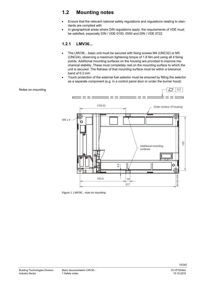
1.2.1 LMV36... • The LMV36... basic unit must be secured with fixing screws M4 (UNC32) or M5
(UNC24), observing a maximum tightening torque of 1.8 Nm and using all 4 fixing points. Additional mounting surfaces on the housing are provided to improve me-chanical stability. These must completely rest on the mounting surface to which the unit is secured. The flatness of that mounting surface must be within a tolerance band of 0.3 mm
• Touch protection of the external fuel selector must be ensured by fitting the selector as a separate component (e.g. in a control panel door or under the burner hood)
122
(103.5)
6.5
103.5 10
217
M5 x 4
0,3
Bild
365
./040
9
Additional mountingsurfaces
Outer contour of housing
Figure 1: LMV36... note on mounting
Notes on mounting
16/242
Building Technologies Division Basic documentation LMV36... CC1P7544en Industry Sector 1 Safety notes 15.10.2010
1.2.2 AGM60...
0,3
85
110
101 69M4 (4x)
6,5
97
10 (2x)
Bild 258e/0309
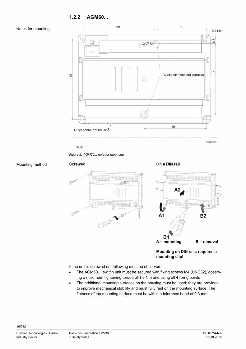
Figure 2: AGM60... note for mounting Screwed On a DIN rail
A = mounting B = removal
Mounting on DIN rails requires a mounting clip!
If the unit is screwed on, following must be observed: • The AGM60… switch unit must be secured with fixing screws M4 (UNC32), observ-
ing a maximum tightening torque of 1.8 Nm and using all 4 fixing points • The additional mounting surfaces on the housing must be used; they are provided
to improve mechanical stability and must fully rest on the mounting surface. The flatness of the mounting surface must be within a tolerance band of 0.3 mm
Notes for mounting
Mounting method
17/242
Building Technologies Division Basic documentation LMV36... CC1P7544en Industry Sector 1 Safety notes 15.10.2010
1.3 Installation notes • Always run the high-voltage ignition cables separate from the unit and other cables
while observing the greatest possible distances • Ensure that the electrical wiring inside the boiler is in compliance with national and
local safety regulations • Mains power must always be supplied via L and N. This means that no potential dif-
ferential must exist between the neutral conductor N and protective earth PE • Phase and neutral conductor must not be interchanged (dangerous malfunctions,
loss of protection against electric shock hazard, etc.) • Make certain that strain relief of the connected cables is in compliance with the re-
levant standards (e.g. as per DIN EN 60730 and DIN EN 60335) • Ensure that spliced wires cannot get into contact with neighboring terminals. Use
adequate ferrules • Run the high-voltage ignition cable completely separate from all other cables • The burner manufacturer must protect unused terminals of LMV36... and AGM60...
by fitting dummy plugs (exception: X64 (reserved) and X74) • When making the wiring, ensure that the AC 120 V sections is strictly separated
from other voltage sections, thus ensuring protection against electric shock hazard (for more detailed information, refer to chapter Electrical connection of LMV36... and AGM60...)
• The plugs of connecting line for the LMV36…, must be connected or disconnected only when the plant is dead (all-polar disconnection), since the BCI does not ensure safe separation from mains voltage
• AGV50... signal cable from LMV36... and AZL2... Since the BCI carries FELV (refer to chapter Electrical connection of LMV36... and AGM60...), use of the AGV50… signal cable for connection from the LMV36... to the AZL2... is mandatory, or observe the respective specification. The cable is specified for use under the burner hood. When using other types of cable that do not conform to the specification, protection against electric shock hazard is not necessarily en-sured
• Do not lay signal cable AGV50... from the LMV36... to the AZL2... together with other cables
• Service operation with a longer signal cable from the LMV36...: If a longer signal cable is required for service work for example (short-time usage, <24 hours), note that the above application under the burner hood no longer applies and, for this reason, the signal cable can be subjected to increased mechanical stress. In that case, use a reinforced signal cable
• Both the AGV50... signal cable and the AZL2... must be shipped and stored so that no damage due to dust and water can occur when the products are used in the field
• To ensure protection against electric shock hazard, make certain that – prior to switching on power – the AGV50... signal cable is correctly connected to the AZL2...
• The AZL2... must be used in a dry and clean environment • The connection between the actuators and the regulating units for fuel and com-
bustion air or any other regulating units must be form-fitted
18/242
Building Technologies Division Basic documentation LMV36... CC1P7544en Industry Sector 1 Safety notes 15.10.2010
1.3.1 Use of the AGM60... • To ensure correct fuel changeover, output Safety valve (SV) / magnetic clutch
(X6-03.3) must be connected to the respective input of the AGM60... (X32-01.5), the reason being the following: Depending on the signal level at this output, the AGM60... sends the point in time for fuel changeover to the LMV36...
Caution! • The AGM60... must always be powered via the LMV36... basic unit and never di-
rectly by mains voltage • The live conductor for fuel changeover (refer to chapter Fuel changeover) must al-
ways be picked up at terminal X31-01.4 of the AGM60… • Connecting cable between LMV36... and AGM60... (also refer to chapter Makeup of
system): Use of this connecting cable is mandatory (available as an accessory item, refer to chapter Type summary)
1.4 Electrical connections of LMV36... and AGM60...
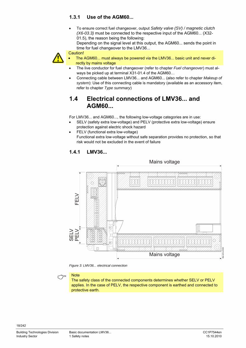
For LMV36... and AGM60..., the following low-voltage categories are in use: • SELV (safety extra low-voltage) and PELV (protective extra low-voltage) ensure
protection against electric shock hazard • FELV (functional extra low-voltage)
Functional extra low-voltage without safe separation provides no protection, so that risk would not be excluded in the event of failure
1.4.1 LMV36...
Mains voltage
SE
LVP
ELV
FELV
Mains voltage
Figure 3: LMV36... electrical connection
Note The safety class of the connected components determines whether SELV or PELV applies. In the case of PELV, the respective component is earthed and connected to protective earth.
19/242
Building Technologies Division Basic documentation LMV36... CC1P7544en Industry Sector 1 Safety notes 15.10.2010
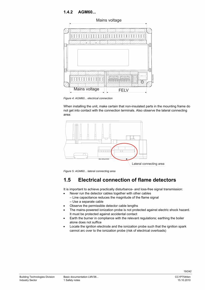
1.4.2 AGM60...
Mains voltage FELV
Mains voltage
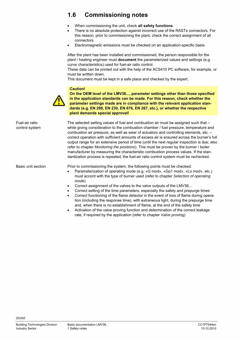
Figure 4: AGM60... electrical connection When installing the unit, make certain that non-insulated parts in the mounting frame do not get into contact with the connection terminals. Also observe the lateral connecting area:
Bild 263e/0309
Lateral connecting area Figure 5: AGM60... lateral connecting area
1.5 Electrical connection of flame detectors It is important to achieve practically disturbance- and loss-free signal transmission: • Never run the detector cables together with other cables
– Line capacitance reduces the magnitude of the flame signal – Use a separate cable
• Observe the permissible detector cable lengths • The mains-powered ionization probe is not protected against electric shock hazard.
It must be protected against accidental contact • Earth the burner in compliance with the relevant regulations; earthing the boiler
alone does not suffice • Locate the ignition electrode and the ionization probe such that the ignition spark
cannot arc over to the ionization probe (risk of electrical overloads)
20/242
Building Technologies Division Basic documentation LMV36... CC1P7544en Industry Sector 1 Safety notes 15.10.2010
1.6 Commissioning notes • When commissioning the unit, check all safety functions • There is no absolute protection against incorrect use of the RASTx connectors. For
this reason, prior to commissioning the plant, check the correct assignment of all connectors
• Electromagnetic emissions must be checked on an application-specific basis After the plant has been installed and commissioned, the person responsible for the plant / heating engineer must document the parameterized values and settings (e.g. curve characteristics) used for fuel-air ratio control. These data can be printed out with the help of the ACS410 PC software, for example, or must be written down. This document must be kept in a safe place and checked by the expert.
Caution! On the OEM level of the LMV36..., parameter settings other than those specified in the application standards can be made. For this reason, check whether the parameter settings made are in compliance with the relevant application stan-dards (e.g. EN 298, EN 230, EN 676, EN 267, etc.), or whether the respective plant demands special approval!
The selected setting values of fuel and combustion air must be assigned such that – while giving consideration to the combustion chamber / fuel pressure, temperature and combustion air pressure, as well as wear of actuators and controlling elements, etc. – correct operation with sufficient amounts of excess air is ensured across the burner’s full output range for an extensive period of time (until the next regular inspection is due; also refer to chapter Monitoring the positions). This must be proven by the burner / boiler manufacturer by measuring the characteristic combustion process values. If the stan-dardization process is repeated, the fuel-air ratio control system must be rechecked. Prior to commissioning the system, the following points must be checked: • Parameterization of operating mode (e.g. «G mod», «Gp1 mod», «Lo mod», etc.)
must accord with the type of burner used (refer to chapter Selection of operating mode)
• Correct assignment of the valves to the valve outputs of the LMV36... • Correct setting of the time parameters, especially the safety and prepurge times • Correct functioning of the flame detector in the event of loss of flame during opera-
tion (including the response time), with extraneous light, during the prepurge time and, when there is no establishment of flame, at the end of the safety time
• Activation of the valve proving function and determination of the correct leakage rate, if required by the application (refer to chapter Valve proving)
Fuel-air ratio control system
Basic unit section
21/242
Building Technologies Division Basic documentation LMV36... CC1P7544en Industry Sector 1 Safety notes 15.10.2010
The functions of the following available or required input status signals must be check-ed: • Air pressure • Minimum gas pressure / maximum gas pressure or POC • Gas pressure valve proving • Minimum oil pressure and maximum oil pressure • Safety loop (e.g. safety limiter)
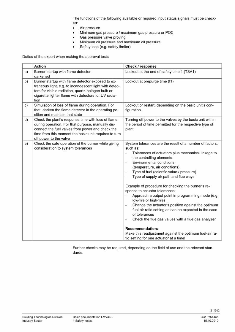
Duties of the expert when making the approval tests
Action Check / response a) Burner startup with flame detector
darkened Lockout at the end of safety time 1 (TSA1)
b) Burner startup with flame detector exposed to ex-traneous light, e.g. to incandescent light with detec-tors for visible radiation, quartz-halogen bulb or cigarette lighter flame with detectors for UV radia-tion
Lockout at prepurge time (t1)
c) Simulation of loss of flame during operation. For that, darken the flame detector in the operating po-sition and maintain that state
Lockout or restart, depending on the basic unit’s con-figuration
d) Check the plant’s response time with loss of flame during operation. For that purpose, manually dis-connect the fuel valves from power and check the time from this moment the basic unit requires to turn off power to the valve
Turning off power to the valves by the basic unit within the period of time permitted for the respective type of plant
e) Check the safe operation of the burner while giving consideration to system tolerances
System tolerances are the result of a number of factors, such as: - Tolerances of actuators plus mechanical linkage to
the controlling elements - Environmental conditions
(temperature, air conditions) - Type of fuel (calorific value / pressure) - Type of supply air path and flue ways Example of procedure for checking the burner’s re-sponse to actuator tolerances: - Approach a output point in programming mode (e.g.
low-fire or high-fire) - Change the actuator’s position against the optimum
fuel-air ratio setting as can be expected in the case of tolerances
- Check the flue gas values with a flue gas analyzer Recommendation: Make this readjustment against the optimum fuel-air ra-tio setting for one actuator at a time!
Further checks may be required, depending on the field of use and the relevant stan-dards.
22/242
Building Technologies Division Basic documentation LMV36... CC1P7544en Industry Sector 1 Safety notes 15.10.2010
1.7 Notes on settings and parameter settings • When adjusting the electronic fuel-air ratio control system integrated in the
LMV36..., allow for sufficient amounts of excess air since – over a period of time – the flue gas settings are affected by a number of factors (e.g. density of air, wear of actuators and controlling elements, etc.). For this reason, the flue gas values initially set must be checked at regular intervals
• To safeguard against inadvertent or unauthorized parameter transfer from the PC software to the basic unit, the OEM must assign an individual burner identification (ID) for each burner. Compliance with this regulation is mandatory to ensure that the LMV36... system prevents the transfer of parameter sets of some other plant (with inadequate and possibly dangerous parameter values) to the LMV36... system via the PC tool. In addition, the fuel-air ratio control parameters must be manually ap-proached and the combustion values checked
• With the LMV36... system, it is to be noted that the unit’s characteristics are deter-mined primarily by the specific parameter settings rather than the type of unit. This means that, among other things, each time a plant is commissioned, the parameter settings must be checked and the LMV36... must not be transferred from one plant to another without adapting the parameter settings to the new plant
• When using the ACS410 PC software, the safety notes given in the relevant Instal-lation and Operating Instructions (J7352) must also be observed
• A password protects the parameter level against unauthorized access. The OEM al-locates individual passwords to the setting levels he can access. The default pass-words used by Siemens must be changed by the OEM. These passwords are confi-dential and may only be given to persons authorized to access such setting levels
• The responsibility for setting the parameters lies with the person who – in accor-dance with his access rights – made changes to the respective setting level
In particular, the OEM (burner and / or boiler manufacturer) assumes responsibil-ity for the correct parameter settings in compliance with the standards covering the specific applications (e.g. EN 676, EN 267, EN 1643, etc.).
23/242
Building Technologies Division Basic documentation LMV36... CC1P7544en Industry Sector 1 Safety notes 15.10.2010
1.8 Standards and certificates
Conformity to EEC directives - Electromagnetic compatibility EMC (immunity) - Directive for gas-fired appliances - Low-voltage directive - Pressure equipment directive
2004/108/EC 90/396/EEC 2006/95/EC 97/23/EC
ISO 9001: 2010 Cert. 00739
ISO 14001: 2010 Cert. 38233
• Identification code as per EN 230 / EN 298, chapter 4 F T / M C L B B
1.9 Service notes • If fuses are blown, the unit must be returned to Siemens (refer to chapter Warn-
ing notes) • Error diagnostics can only be made via the LMV36... (BCI)
1.10 Life cycle The burner management system LMV36... has a designed lifetime* of 250,000 burner startup cycles which, under normal operating conditions in heating mode, correspond to approx. 10 years of usage (starting from the production date given on the type field). The AGM60... switch unit has a designed lifetime* of 5,000 burner startup cycles which, under normal operating conditions in heating mode, correspond to approx. 10 years of usage (starting from the production date given on the type field). This lifetime is based on the endurance tests specified in EN 230 / EN 298 and the table containing the relevant test documentation published by the European Association of Component Manufacturers (Afecor) (www.afecor.org). The designed lifetime is based on use of the LMV36... / AGM60... according to the manufacturer’s Basic Documentation. When reaching the designed lifetime in terms of the number of burner startup cycles or time of usage, the LMV36... / AGM60... must be replaced by authorized personnel. * The designed lifetime is not the warranty time specified in the Terms of Delivery
1.11 Disposal notes The unit contains electrical and electronic components and must not be disposed of to-gether with domestic waste. Local and currently valid legislation must be observe
LMV36...
AGM60...
General
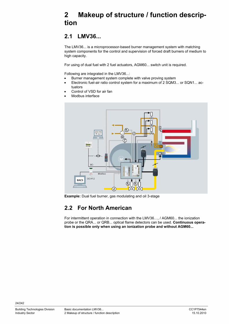
24/242
Building Technologies Division Basic documentation LMV36... CC1P7544en Industry Sector 2 Makeup of structure / function description 15.10.2010
2 Makeup of structure / function descrip-tion
2.1 LMV36... The LMV36... is a microprocessor-based burner management system with matching system components for the control and supervision of forced draft burners of medium to high capacity. For using of dual fuel with 2 fuel actuators, AGM60... switch unit is required. Following are integrated in the LMV36...: • Burner management system complete with valve proving system • Electronic fuel-air ratio control system for a maximum of 2 SQM3... or SQN1... ac-
tuators • Control of VSD for air fan • Modbus interface
Example: Dual fuel burner, gas modulating and oil 3-stage
2.2 For North American For intermittent operation in connection with the LMV36…, / AGM60... the ionization probe or the QRA... or QRB... optical flame detectors can be used. Continuous opera-tion is possible only when using an ionization probe and without AGM60...
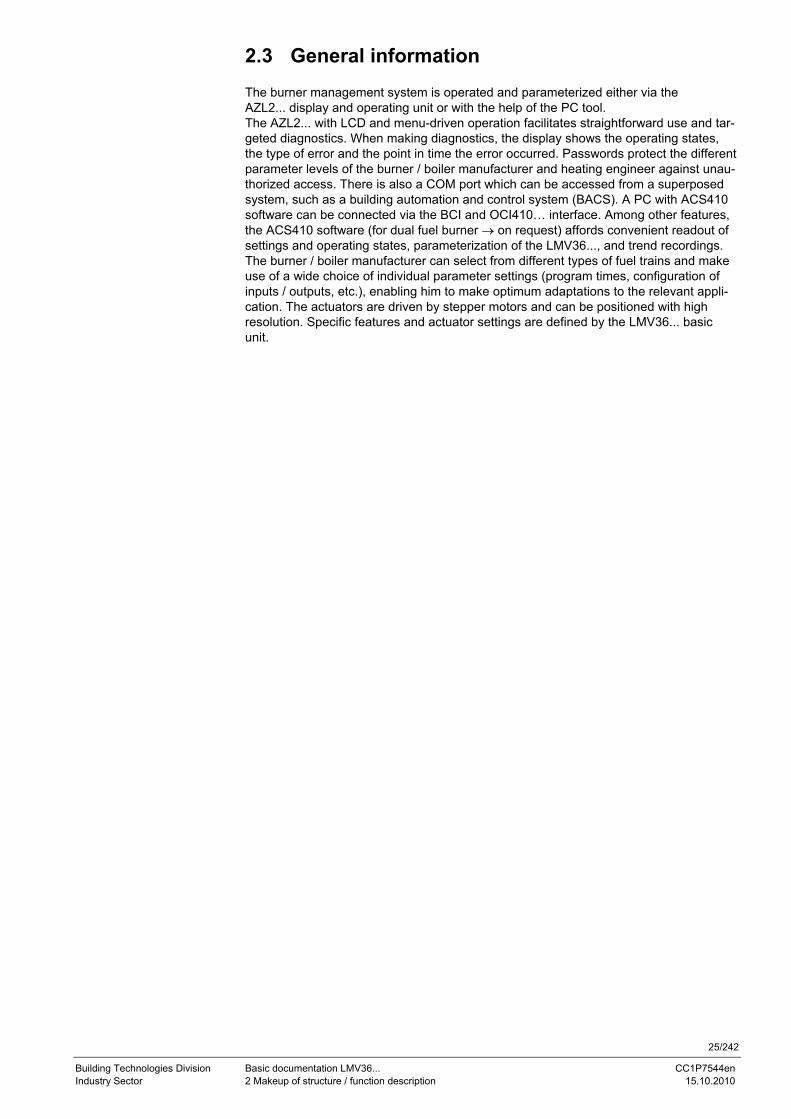
25/242
Building Technologies Division Basic documentation LMV36... CC1P7544en Industry Sector 2 Makeup of structure / function description 15.10.2010
2.3 General information The burner management system is operated and parameterized either via the AZL2... display and operating unit or with the help of the PC tool. The AZL2... with LCD and menu-driven operation facilitates straightforward use and tar-geted diagnostics. When making diagnostics, the display shows the operating states, the type of error and the point in time the error occurred. Passwords protect the different parameter levels of the burner / boiler manufacturer and heating engineer against unau-thorized access. There is also a COM port which can be accessed from a superposed system, such as a building automation and control system (BACS). A PC with ACS410 software can be connected via the BCI and OCI410… interface. Among other features, the ACS410 software (for dual fuel burner → on request) affords convenient readout of settings and operating states, parameterization of the LMV36..., and trend recordings. The burner / boiler manufacturer can select from different types of fuel trains and make use of a wide choice of individual parameter settings (program times, configuration of inputs / outputs, etc.), enabling him to make optimum adaptations to the relevant appli-cation. The actuators are driven by stepper motors and can be positioned with high resolution. Specific features and actuator settings are defined by the LMV36... basic unit.
26/242
Building Technologies Division Basic documentation LMV36... CC1P7544en Industry Sector 2 Makeup of structure / function description 15.10.2010
2.4 AGM60... The AGM60… switch unit connected to the LMV36... serves for changeover of valve control or for feedback signals from the 2 types of fuel. The signals are monitored by the LMV36... basic unit (same as with the single-fuel variant) which, in the event of fault, also triggers shutdown.
Pressure input Fuel0
Pressure input Fuel1
Pressure input LNPE
Fuel0Fuel1
SAFuel
Fuel valve outlets
Fuel valve Fuel0
Fuel valve Fuel1
Fuel actuator Fuel0
Fuel actuator Fuel1
M Actuator air
Fuel selection
LMV...
AGM60...
Bild 264e/0309
Figure 6: AGM60... connected to the LMV36...
2.4.1 Electrical connections of fuel actuators When using only 1 fuel actuator, it must be connected directly to the LMV36... In that case, a connecting cable (AGV61.100) is not required. When using 2 fuel actuators for each type, they must be connected to the AGM60... Fuel selection choices: - Gas / oil - Gas / gas - Oil / oil When wiring the components, we recommend to make the following fuel assignments as standard: Fuel 0 = gas Fuel 1 = oil This can be set via parameter 201 / 301 (refer to chapter Selection of operating mode). Following switching’s of inputs and outputs are made via AGM60...: - Fuel at the LMV36... - Fuel valve - Pressure switch or POC - Actuator (SQM3... or SQN1...)
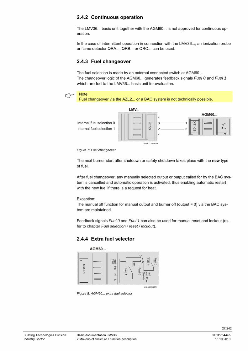
27/242
Building Technologies Division Basic documentation LMV36... CC1P7544en Industry Sector 2 Makeup of structure / function description 15.10.2010
2.4.2 Continuous operation The LMV36... basic unit together with the AGM60... is not approved for continuous op-eration. In the case of intermittent operation in connection with the LMV36..., an ionization probe or flame detector QRA..., QRB... or QRC... can be used.
2.4.3 Fuel changeover The fuel selection is made by an external connected switch at AGM60... The changeover logic of the AGM60... generates feedback signals Fuel 0 and Fuel 1 which are fed to the LMV36... basic unit for evaluation.
Note Fuel changeover via the AZL2... or a BAC system is not technically possible.
Bild 373e/0409
AGM60...
Internal fuel selection 1Internal fuel selection 0
X31-02
01
P
LMV...
X5-
03
4
3
2
1
1
2
Figure 7: Fuel changeover The next burner start after shutdown or safety shutdown takes place with the new type of fuel. After fuel changeover, any manually selected output or output called for by the BAC sys-tem is cancelled and automatic operation is activated, thus enabling automatic restart with the new fuel if there is a request for heat. Exception: The manual off function for manual output and burner off (output = 0) via the BAC sys-tem are maintained. Feedback signals Fuel 0 and Fuel 1 can also be used for manual reset and lockout (re-fer to chapter Fuel selection / reset / lockout).
2.4.4 Extra fuel selector
AGM60...
X31-01
1 SWI
FuelPE
NL
Bild 266/0309 Figure 8: AGM60... extra fuel selector
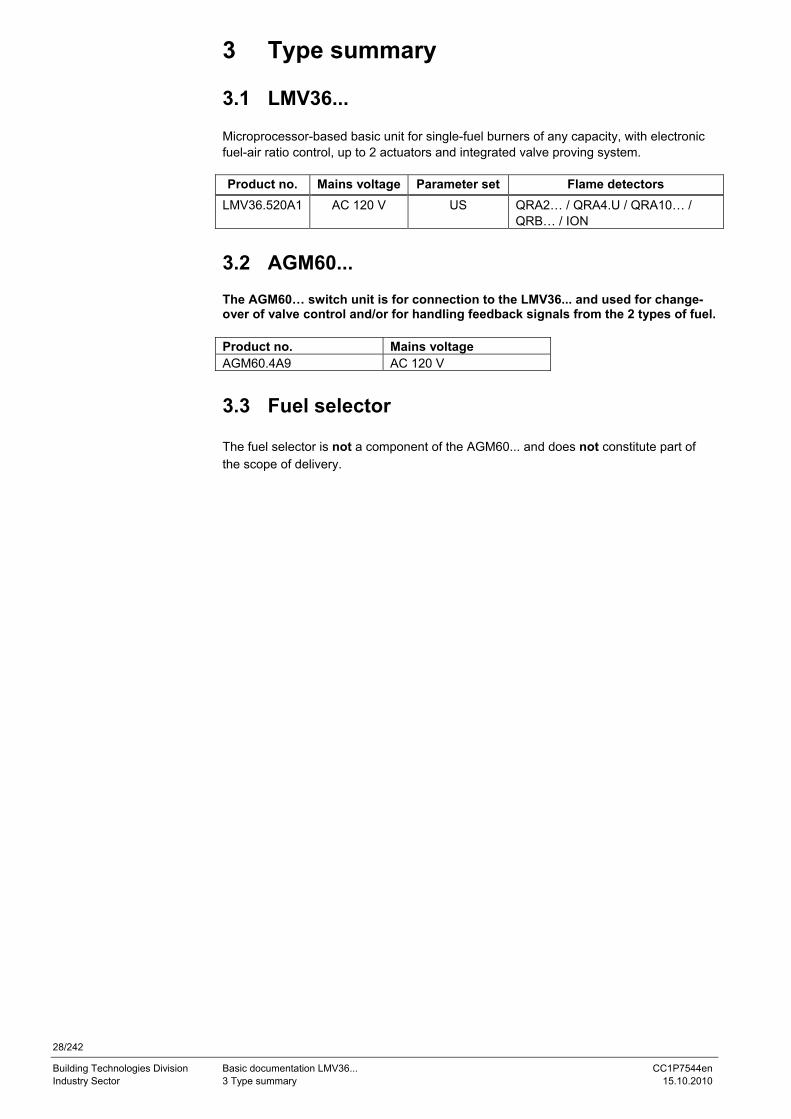
28/242
Building Technologies Division Basic documentation LMV36... CC1P7544en Industry Sector 3 Type summary 15.10.2010
3 Type summary
3.1 LMV36... Microprocessor-based basic unit for single-fuel burners of any capacity, with electronic fuel-air ratio control, up to 2 actuators and integrated valve proving system. Product no. Mains voltage Parameter set Flame detectors
LMV36.520A1 AC 120 V US QRA2… / QRA4.U / QRA10… / QRB… / ION
3.2 AGM60... The AGM60… switch unit is for connection to the LMV36... and used for change-over of valve control and/or for handling feedback signals from the 2 types of fuel. Product no. Mains voltage AGM60.4A9 AC 120 V
3.3 Fuel selector The fuel selector is not a component of the AGM60... and does not constitute part of the scope of delivery.
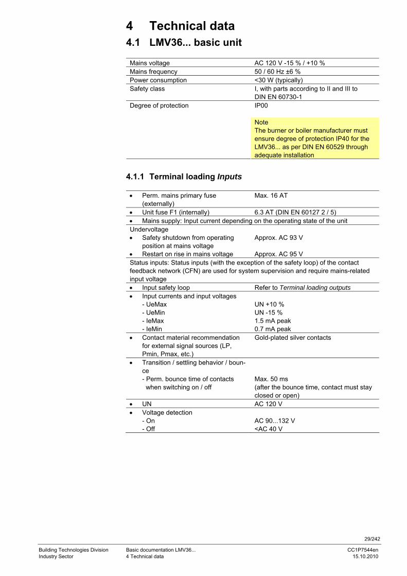
29/242
Building Technologies Division Basic documentation LMV36... CC1P7544en Industry Sector 4 Technical data 15.10.2010
4 Technical data 4.1 LMV36... basic unit
Mains voltage AC 120 V -15 % / +10 % Mains frequency 50 / 60 Hz ±6 % Power consumption <30 W (typically) Safety class I, with parts according to II and III to
DIN EN 60730-1 IP00
Degree of protection
Note The burner or boiler manufacturer must ensure degree of protection IP40 for the LMV36... as per DIN EN 60529 through adequate installation
4.1.1 Terminal loading Inputs
• Perm. mains primary fuse (externally)
Max. 16 AT
• Unit fuse F1 (internally) 6.3 AT (DIN EN 60127 2 / 5) • Mains supply: Input current depending on the operating state of the unit Undervoltage • Safety shutdown from operating
position at mains voltage Approx. AC 93 V
• Restart on rise in mains voltage Approx. AC 95 V Status inputs: Status inputs (with the exception of the safety loop) of the contact feedback network (CFN) are used for system supervision and require mains-related input voltage • Input safety loop Refer to Terminal loading outputs • Input currents and input voltages
- UeMax - UeMin - IeMax - IeMin
UN +10 % UN -15 % 1.5 mA peak 0.7 mA peak
• Contact material recommendation for external signal sources (LP, Pmin, Pmax, etc.)
Gold-plated silver contacts
• Transition / settling behavior / boun-ce - Perm. bounce time of contacts when switching on / off
Max. 50 ms (after the bounce time, contact must stay closed or open)
• UN AC 120 V • Voltage detection
- On - Off
AC 90...132 V <AC 40 V
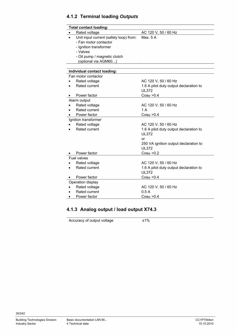
30/242
Building Technologies Division Basic documentation LMV36... CC1P7544en Industry Sector 4 Technical data 15.10.2010
4.1.2 Terminal loading Outputs
Total contact loading: • Rated voltage AC 120 V, 50 / 60 Hz • Unit input current (safety loop) from:
- Fan motor contactor - Ignition transformer - Valves - Oil pump / magnetic clutch (optional via AGM60...)
Max. 5 A
Individual contact loading: Fan motor contactor • Rated voltage AC 120 V, 50 / 60 Hz • Rated current 1.6 A pilot duty output declaration to
UL372 • Power factor Cosϕ >0.4 Alarm output • Rated voltage AC 120 V, 50 / 60 Hz • Rated current 1 A • Power factor Cosϕ >0.4 Ignition transformer • Rated voltage AC 120 V, 50 / 60 Hz • Rated current 1.6 A pilot duty output declaration to
UL372 or 250 VA ignition output declaration to UL372
• Power factor Cosϕ >0.2 Fuel valves • Rated voltage AC 120 V, 50 / 60 Hz • Rated current 1.6 A pilot duty output declaration to
UL372 • Power factor Cosϕ >0.4 Operation display • Rated voltage AC 120 V, 50 / 60 Hz • Rated current 0.5 A • Power factor Cosϕ >0.4
4.1.3 Analog output / load output X74.3
Accuracy of output voltage ±1%
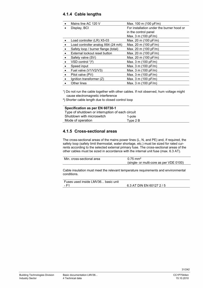
31/242
Building Technologies Division Basic documentation LMV36... CC1P7544en Industry Sector 4 Technical data 15.10.2010
4.1.4 Cable lengths
• Mains line AC 120 V Max. 100 m (100 pF/m) • Display, BCI For installation under the burner hood or
in the control panel Max. 3 m (100 pF/m)
• Load controller (LR) X5-03 Max. 20 m (100 pF/m) • Load controller analog X64 (24 mA) Max. 20 m (100 pF/m) • Safety loop / burner flange (total) Max. 20 m (100 pF/m) • External lockout reset button Max. 20 m (100 pF/m) • Safety valve (SV) Max. 20 m (100 pF/m) • VSD control ¹)²) Max. 3 m (100 pF/m) • Speed input Max. 3 m (100 pF/m) • Fuel valve (V1/V2/V3) Max. 3 m (100 pF/m) • Pilot valve (PV) Max. 3 m (100 pF/m) • Ignition transformer (Z) Max. 3 m (100 pF/m) • Other lines Max. 3 m (100 pF/m)
¹) Do not run the cable together with other cables. If not observed, hum voltage might cause electromagnetic interference ²) Shorter cable length due to closed control loop Specification as per EN 60730-1 Type of shutdown or interruption of each circuit Shutdown with microswitch 1-pole Mode of operation Type 2 B
4.1.5 Cross-sectional areas The cross-sectional areas of the mains power lines (L, N, and PE) and, if required, the safety loop (safety limit thermostat, water shortage, etc.) must be sized for rated cur-rents according to the selected external primary fuse. The cross-sectional areas of the other cables must be sized in accordance with the internal unit fuse (max. 6.3 AT). Min. cross-sectional area 0.75 mm²
(single- or multi-core as per VDE 0100) Cable insulation must meet the relevant temperature requirements and environmental conditions. Fuses used inside LMV36... basic unit - F1 6.3 AT DIN EN 60127 2 / 5
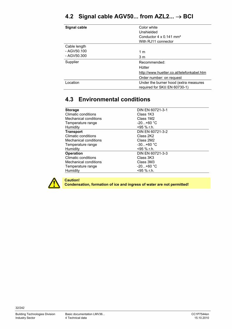
32/242
Building Technologies Division Basic documentation LMV36... CC1P7544en Industry Sector 4 Technical data 15.10.2010
4.2 Signal cable AGV50... from AZL2... → BCI Signal cable Color white
Unshielded Conductor 4 x 0.141 mm² With RJ11 connector
Cable length - AGV50.100 - AGV50.300
1 m 3 m
Supplier Recommended: Hütter http://www.huetter.co.at/telefonkabel.htm Order number: on request
Location Under the burner hood (extra measures required for SKII EN 60730-1)
4.3 Environmental conditions Storage DIN EN 60721-3-1 Climatic conditions Class 1K3 Mechanical conditions Class 1M2 Temperature range -20...+60 °C Humidity <95 % r.h. Transport DIN EN 60721-3-2 Climatic conditions Class 2K2 Mechanical conditions Class 2M2 Temperature range -30...+60 °C Humidity <95 % r.h. Operation DIN EN 60721-3-3 Climatic conditions Class 3K3 Mechanical conditions Class 3M3 Temperature range -20...+60 °C Humidity <95 % r.h.
Caution! Condensation, formation of ice and ingress of water are not permitted!
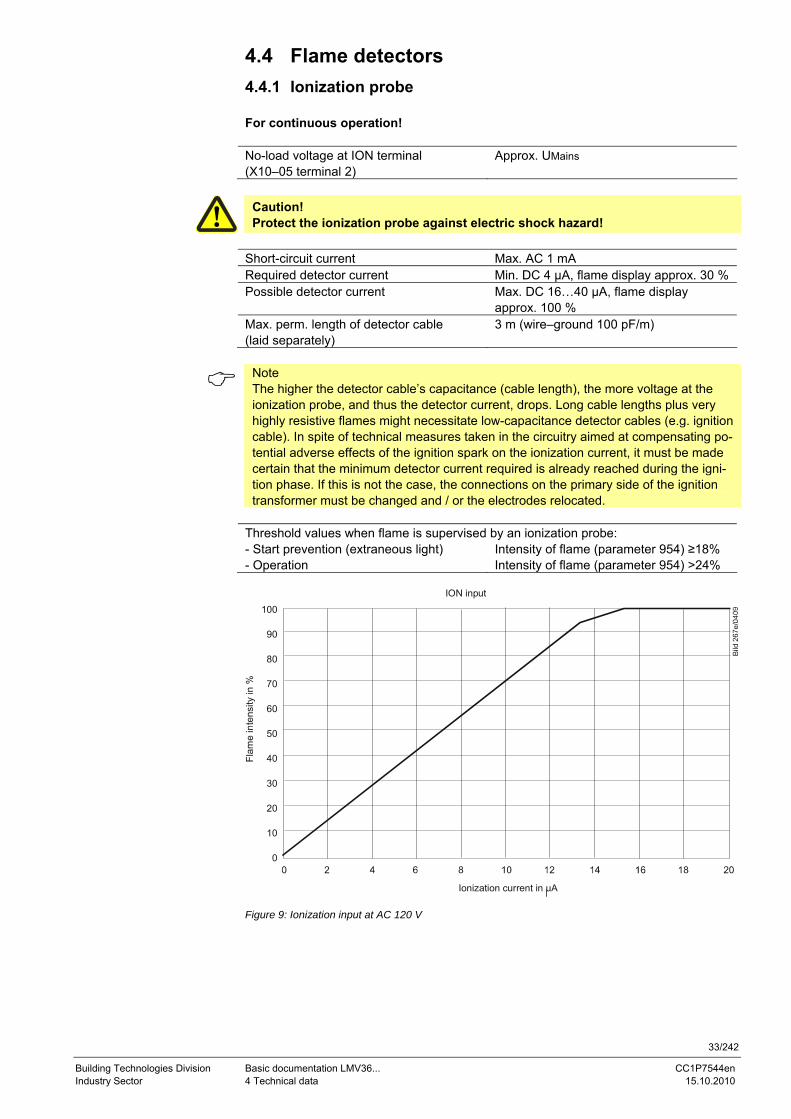
33/242
Building Technologies Division Basic documentation LMV36... CC1P7544en Industry Sector 4 Technical data 15.10.2010
4.4 Flame detectors 4.4.1 Ionization probe For continuous operation! No-load voltage at ION terminal (X10–05 terminal 2)
Approx. UMains
Caution! Protect the ionization probe against electric shock hazard!
Short-circuit current Max. AC 1 mA Required detector current Min. DC 4 µA, flame display approx. 30 % Possible detector current Max. DC 16…40 µA, flame display
approx. 100 % Max. perm. length of detector cable (laid separately)
3 m (wire–ground 100 pF/m)
Note The higher the detector cable’s capacitance (cable length), the more voltage at the ionization probe, and thus the detector current, drops. Long cable lengths plus very highly resistive flames might necessitate low-capacitance detector cables (e.g. ignition cable). In spite of technical measures taken in the circuitry aimed at compensating po-tential adverse effects of the ignition spark on the ionization current, it must be made certain that the minimum detector current required is already reached during the igni-tion phase. If this is not the case, the connections on the primary side of the ignition transformer must be changed and / or the electrodes relocated.
Threshold values when flame is supervised by an ionization probe: - Start prevention (extraneous light) Intensity of flame (parameter 954) ≥18% - Operation Intensity of flame (parameter 954) >24%
ION input
Flam
e in
tens
ity in
%
100
90
80
70
60
50
40
30
20
10
0
Ionization current in uA Figure 9: Ionization input at AC 120 V
34/242
Building Technologies Division Basic documentation LMV36... CC1P7544en Industry Sector 4 Technical data 15.10.2010
4.4.2 UV flame detectors QRA2… / QRA4.U / QRA10…
Caution! If flame detectors QRA2… / QRA4.U / QRA10... are used for flame supervision with the LMV36..., it must be ensured that the basic unit is permanently con-nected to power (conforming to EN 230 / EN 298), thus enabling the system to detect flame detector failures during startup and shutdown. Generally, the sys-tem works with QRA... flame detectors in intermittent operation. For technical data, refer to Data Sheet N7712 covering QRA2... / QRA10... UV flame detector! For technical data, refer to Data Sheet N7711 covering QRA4.U UV flame detec-tor!
Threshold values when flame is supervised by QRA...: - Start prevention (extraneous light) Intensity of flame (parameter 954) ≥18% - Operation Intensity of flame (parameter 954) >24%

35/242
Building Technologies Division Basic documentation LMV36... CC1P7544en Industry Sector 4 Technical data 15.10.2010
4.4.3 Photoresistive flame detectors QRB… No-load voltage at QRB... terminal (X10–05 terminal 3)
Approx. DC 5 V
Max. perm. length of QRB... detector cable (laid separately)
3 m (wire – wire 100 pF/m)
Note A detector resistance of RF <500 Ω is identified as a short-circuit and leads to safety shutdown in operation as if the flame had been lost.
For this reason, before considering the use of a highly sensitive photoresistive detector (QRB1B... or QRB3S), it should be checked whether this type of flame detector is in-deed required! Increased line capacitance between QRB... connection and mains live wire L has an adverse effect on the sensitivity and increases the risk of damaged flame detectors due to overvoltage. Always run detector cables separately! Threshold values when flame is supervised by QRB...: Start prevention (extraneous light) with RQRB
<400 kΩ Intensity of flame ≥10%
Operation with RQRB <230 kΩ Intensity of flame >16%
Short-circuit detection with RQRB <0.5 kΩ
0,1 1 10 100 1000
7540
d04e
/101
0
Figure 10: QRB… input at AC 120 V
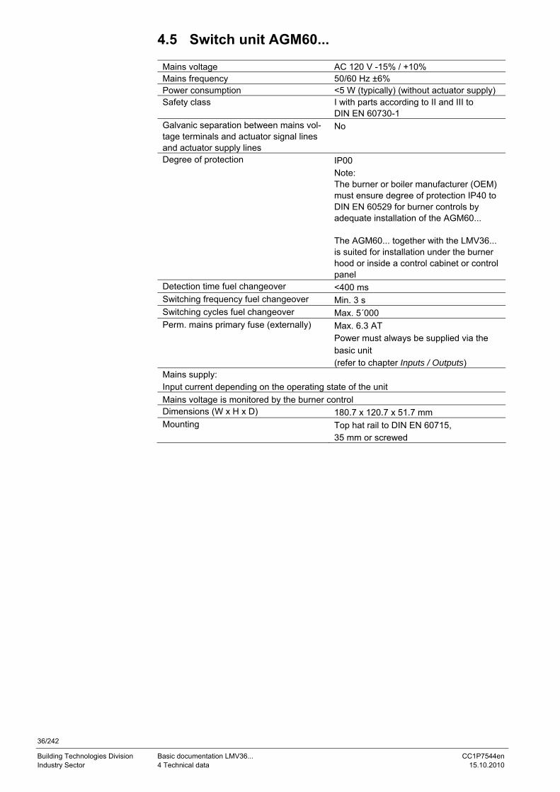
36/242
Building Technologies Division Basic documentation LMV36... CC1P7544en Industry Sector 4 Technical data 15.10.2010
4.5 Switch unit AGM60...
Mains voltage AC 120 V -15% / +10% Mains frequency 50/60 Hz ±6% Power consumption <5 W (typically) (without actuator supply) Safety class I with parts according to II and III to
DIN EN 60730-1 Galvanic separation between mains vol-tage terminals and actuator signal lines and actuator supply lines
No
Degree of protection IP00 Note: The burner or boiler manufacturer (OEM) must ensure degree of protection IP40 to DIN EN 60529 for burner controls by adequate installation of the AGM60... The AGM60... together with the LMV36... is suited for installation under the burner hood or inside a control cabinet or control panel
Detection time fuel changeover <400 ms Switching frequency fuel changeover Min. 3 s Switching cycles fuel changeover Max. 5´000 Perm. mains primary fuse (externally) Max. 6.3 AT
Power must always be supplied via the basic unit (refer to chapter Inputs / Outputs)
Mains supply: Input current depending on the operating state of the unit Mains voltage is monitored by the burner control Dimensions (W x H x D) 180.7 x 120.7 x 51.7 mm Mounting Top hat rail to DIN EN 60715,
35 mm or screwed
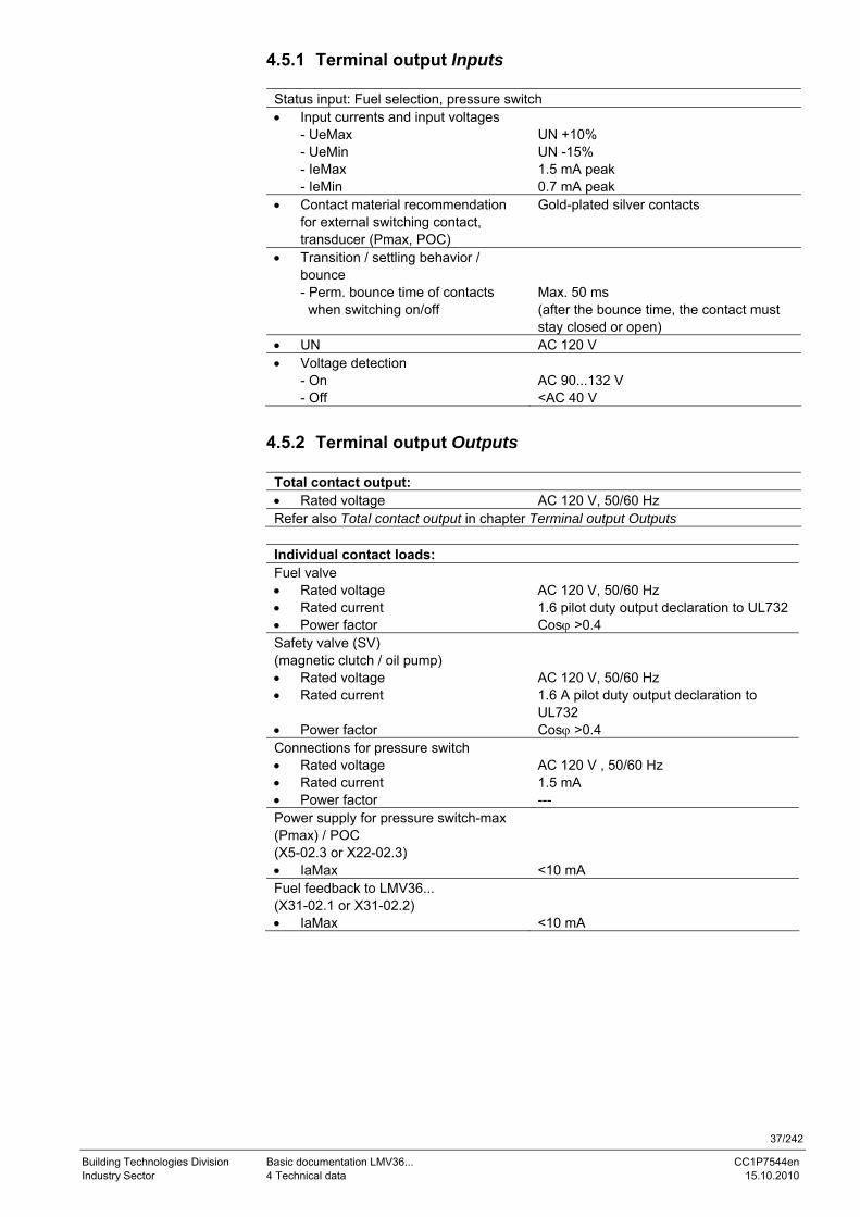
37/242
Building Technologies Division Basic documentation LMV36... CC1P7544en Industry Sector 4 Technical data 15.10.2010
4.5.1 Terminal output Inputs
Status input: Fuel selection, pressure switch • Input currents and input voltages
- UeMax - UeMin - IeMax - IeMin
UN +10% UN -15% 1.5 mA peak 0.7 mA peak
• Contact material recommendation for external switching contact, transducer (Pmax, POC)
Gold-plated silver contacts
• Transition / settling behavior / bounce - Perm. bounce time of contacts when switching on/off
Max. 50 ms (after the bounce time, the contact must stay closed or open)
• UN AC 120 V • Voltage detection
- On - Off
AC 90...132 V <AC 40 V
4.5.2 Terminal output Outputs
Total contact output: • Rated voltage AC 120 V, 50/60 Hz Refer also Total contact output in chapter Terminal output Outputs
Individual contact loads: Fuel valve • Rated voltage AC 120 V, 50/60 Hz • Rated current 1.6 pilot duty output declaration to UL732 • Power factor Cosϕ >0.4 Safety valve (SV) (magnetic clutch / oil pump)
• Rated voltage AC 120 V, 50/60 Hz • Rated current 1.6 A pilot duty output declaration to
UL732 • Power factor Cosϕ >0.4 Connections for pressure switch • Rated voltage AC 120 V , 50/60 Hz • Rated current 1.5 mA • Power factor --- Power supply for pressure switch-max (Pmax) / POC (X5-02.3 or X22-02.3)
• IaMax <10 mA Fuel feedback to LMV36... (X31-02.1 or X31-02.2)
• IaMax <10 mA
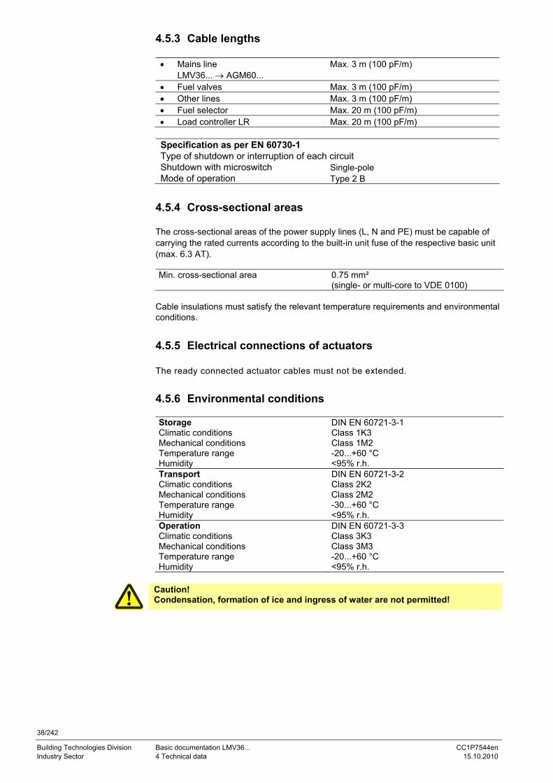
38/242
Building Technologies Division Basic documentation LMV36... CC1P7544en Industry Sector 4 Technical data 15.10.2010
4.5.3 Cable lengths
• Mains line LMV36... → AGM60...
Max. 3 m (100 pF/m)
• Fuel valves Max. 3 m (100 pF/m) • Other lines Max. 3 m (100 pF/m) • Fuel selector Max. 20 m (100 pF/m) • Load controller LR Max. 20 m (100 pF/m)
Specification as per EN 60730-1 Type of shutdown or interruption of each circuit Shutdown with microswitch Single-pole Mode of operation Type 2 B
4.5.4 Cross-sectional areas The cross-sectional areas of the power supply lines (L, N and PE) must be capable of carrying the rated currents according to the built-in unit fuse of the respective basic unit (max. 6.3 AT). Min. cross-sectional area 0.75 mm²
(single- or multi-core to VDE 0100) Cable insulations must satisfy the relevant temperature requirements and environmental conditions.
4.5.5 Electrical connections of actuators The ready connected actuator cables must not be extended.
4.5.6 Environmental conditions Storage DIN EN 60721-3-1 Climatic conditions Class 1K3 Mechanical conditions Class 1M2 Temperature range -20...+60 °C Humidity <95% r.h. Transport DIN EN 60721-3-2 Climatic conditions Class 2K2 Mechanical conditions Class 2M2 Temperature range -30...+60 °C Humidity <95% r.h. Operation DIN EN 60721-3-3 Climatic conditions Class 3K3 Mechanical conditions Class 3M3 Temperature range -20...+60 °C Humidity <95% r.h.
Caution! Condensation, formation of ice and ingress of water are not permitted!
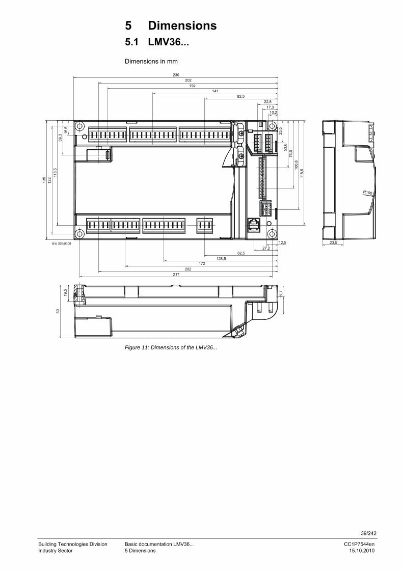
39/242
Building Technologies Division Basic documentation LMV36... CC1P7544en Industry Sector 5 Dimensions 15.10.2010
5 Dimensions 5.1 LMV36... Dimensions in mm
230
202192
14182,5
22,817,3
10,2
16,5
39,3
118,
512
213
5
217202
172128,5
82,527,2
12,5
19,7
60
25,5
53,6
76,6
100,
811
8,5
23,5
R100
19,5
Figure 11: Dimensions of the LMV36...
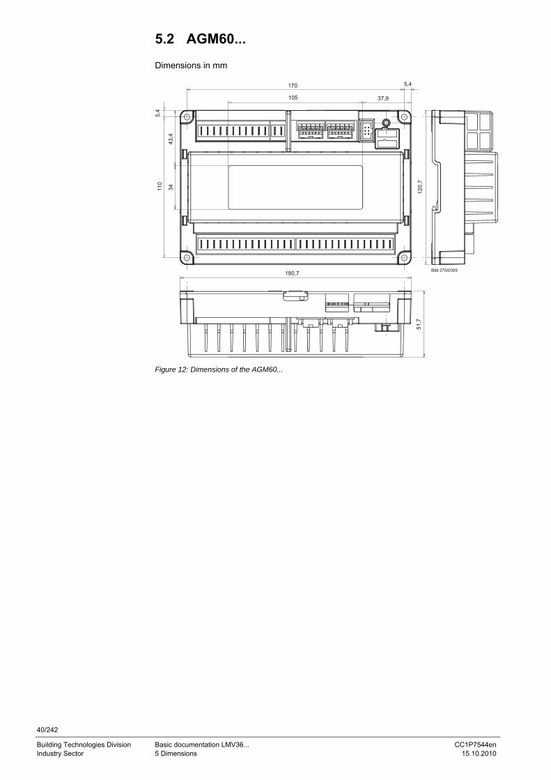
40/242
Building Technologies Division Basic documentation LMV36... CC1P7544en Industry Sector 5 Dimensions 15.10.2010
5.2 AGM60... Dimensions in mm
5,4
110
43,4
34
170
105
5,4
37,9
120,
7
180,7
51,7
Figure 12: Dimensions of the AGM60...
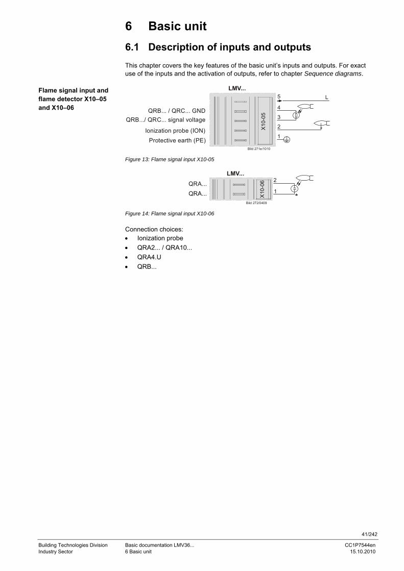
41/242
Building Technologies Division Basic documentation LMV36... CC1P7544en Industry Sector 6 Basic unit 15.10.2010
6 Basic unit
6.1 Description of inputs and outputs This chapter covers the key features of the basic unit’s inputs and outputs. For exact use of the inputs and the activation of outputs, refer to chapter Sequence diagrams.
LMV...
Bild 271e/1010
Protective earth (PE)Ionization probe (ION)
QRB.../ QRC... signal voltageQRB... / QRC... GND
X10
-05
5
4
3
2
1
Figure 13: Flame signal input X10-05
LMV...
Bild 272/0409
QRA...
X10
-06
1
2
Figure 14: Flame signal input X10-06 Connection choices: • Ionization probe • QRA2... / QRA10... • QRA4.U • QRB...
Flame signal input and flame detector X10–05 and X10–06
42/242
Building Technologies Division Basic documentation LMV36... CC1P7544en Industry Sector 6 Basic unit 15.10.2010
6.2 Flame detectors • For display of the flame on the AZL2..., the following general conditions apply:
- Display is subject to various component tolerances, which means that deviations of ± 10% can occur - Note that, for physical reasons, there is no linear relationship between flame display and detector signal values
The LMV36... system can be used with different types of flame detectors. For the correct use of flame detectors, refer to chapter Sequence diagrams. The flame detector used must be correctly parameterized.
Caution! Continuous operation is possible only when using an ionization probe!
In the hardware of the LMV36..., the flame signals are subdivided into 2 groups (group 0 covering types the QRB... and group 1 covering ionization and the QRA…). The flame detector for gas is selected via parameter 221 (fuel 0) / 321 (fuel 1), that for oil via pa-rameter 261 (fuel 0) / 361 (fuel 1).
No. Parameter
221 Gas: Active detector flame evaluation 0 = QRB 1 = ION / QRA
321 Fuel 1 gas: Active detector of flame evaluation 0 = QRB 1 = ION / QRA…
261 Oil: Active detector of flame evaluation 0 = QRB 1 = ION / QRA
361 Fuel 1 oil: Active detector of flame evaluation 0 = QRB 1 = ION / QRA…
43/242
Building Technologies Division Basic documentation LMV36... CC1P7544en Industry Sector 6 Basic unit 15.10.2010
6.2.1 Loss of flame In the event of loss of flame, the unit initiates safety shutdown, followed by a restart, if required. A repetition counter can be used to select the number of flame losses after which the unit shall initiate lockout (refer to chapter Repetition counter).
Error code
Diagnostic code
Meaning for the LMV36... system
7 0 Loss of flame
No. Parameter
186 Software drop-out delay time of flame signal (100 ms) Index 0 = QRB... (0 = inactive, >1) Index 1 = ION / QRA... (0 = inactive, >3 -only 200 ms steps)
187 Fuel 1: Software drop-out delay time of flame signal (100 ms) Index 0 = QRB... (0 = inactive, >1) Index 1 = ION / QRA... (0 = inactive, >3 -only 200 ms steps)
240 Repetition limit value loss of flame 1 = No repetition 2 = 1 Repetition
340 Repetition limit value loss of flame 1 = No repetition 2 = 1 Repetition
280 Repetition limit value loss of flame 1 = No repetition 2 = 1 Repetition
380 Repetition limit value loss of flame 1 = No repetition 2 = 1 Repetition
Caution! The response time of the flame detector leads to an extension of the second safety time (TSA2). This must be taken into account when designing the burner!
6.2.2 Extraneous light Extraneous light during standby (phase 12) leads to prevention of startup, followed by a restart. Extraneous light during the prepurge phase results in immediate lockout. If ex-traneous light occurs during the shutdown phase, the system switches to the safety phase. One repetition is permitted. This means that if the error occurs again the next time the system is shut down, the unit will initiate lockout.
Error code
Diagnostic code
Meaning for the LMV36... system
4 0 Extraneous light during startup 1 Extraneous light during shutdown 2 Extraneous light during startup – prevention of startup
6.2.3 No flame at the end of safety time (TSA) If no flame is established by the end of the first safety time, the unit initiates lockout.
Error code
Diagnostic code
Meaning for the LMV36... system
2 1 No flame at the end of safety time 1 (TSA1) 2 No flame at the end of safety time 2 (TSA2)
44/242
Building Technologies Division Basic documentation LMV36... CC1P7544en Industry Sector 6 Basic unit 15.10.2010
6.2.4 Flame intensity The flame’s intensity can be displayed. It is standardized from 0 to 100%.
No. Parameter
954 Intensity of flame
Note Also refer to chapter Intensity of flame during curve settings.
6.2.5 Supervision of flame detector
Error code
Diagnostic code
Meaning for the LMV36... system
93 3 Short-circuit of flame detector At the QRB… flame detector’s input, the LMV36... checks the detector for short-circuits in operation.
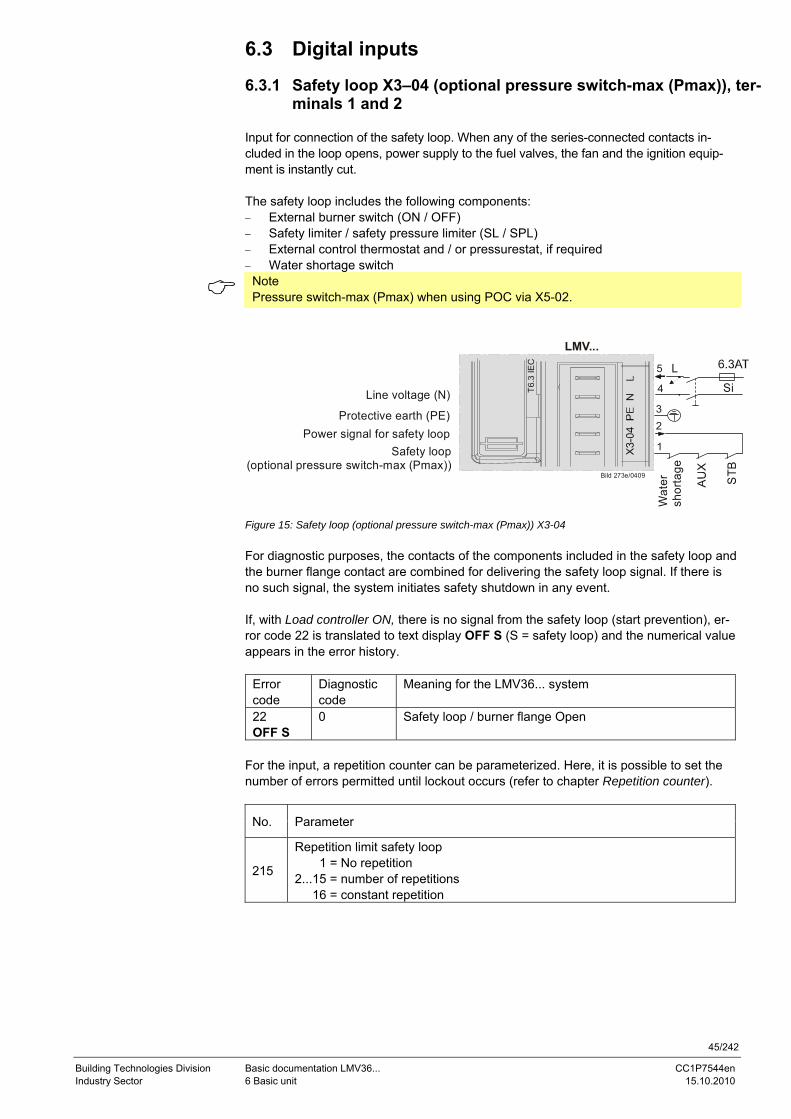
45/242
Building Technologies Division Basic documentation LMV36... CC1P7544en Industry Sector 6 Basic unit 15.10.2010
6.3 Digital inputs 6.3.1 Safety loop X3–04 (optional pressure switch-max (Pmax)), ter-
minals 1 and 2 Input for connection of the safety loop. When any of the series-connected contacts in-cluded in the loop opens, power supply to the fuel valves, the fan and the ignition equip-ment is instantly cut. The safety loop includes the following components: − External burner switch (ON / OFF) − Safety limiter / safety pressure limiter (SL / SPL) − External control thermostat and / or pressurestat, if required − Water shortage switch
Note Pressure switch-max (Pmax) when using POC via X5-02.
LMV...
Bild 273e/0409
T6.3
IEC
Safety loop(optional pressure switch-max (Pmax))
Power signal for safety loopProtective earth (PE)
Line voltage (N)
STB
Wat
ersh
orta
ge
SiL
1
23
4
5
Figure 15: Safety loop (optional pressure switch-max (Pmax)) X3-04 For diagnostic purposes, the contacts of the components included in the safety loop and the burner flange contact are combined for delivering the safety loop signal. If there is no such signal, the system initiates safety shutdown in any event. If, with Load controller ON, there is no signal from the safety loop (start prevention), er-ror code 22 is translated to text display OFF S (S = safety loop) and the numerical value appears in the error history.
Error code
Diagnostic code
Meaning for the LMV36... system
22 OFF S
0 Safety loop / burner flange Open
For the input, a repetition counter can be parameterized. Here, it is possible to set the number of errors permitted until lockout occurs (refer to chapter Repetition counter).
No. Parameter
215
Repetition limit safety loop 1 = No repetition 2...15 = number of repetitions 16 = constant repetition
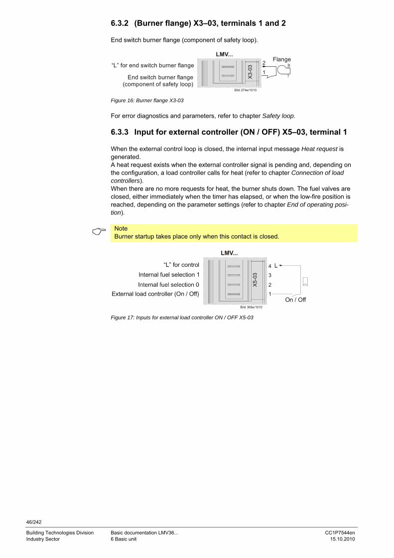
46/242
Building Technologies Division Basic documentation LMV36... CC1P7544en Industry Sector 6 Basic unit 15.10.2010
6.3.2 (Burner flange) X3–03, terminals 1 and 2 End switch burner flange (component of safety loop).
LMV...
Bild 274e/1010
X3-0
3
End switch burner flange(component of safety loop)
“L” for end switch burner flangeFlange2
1
Figure 16: Burner flange X3-03 For error diagnostics and parameters, refer to chapter Safety loop. 6.3.3 Input for external controller (ON / OFF) X5–03, terminal 1 When the external control loop is closed, the internal input message Heat request is generated. A heat request exists when the external controller signal is pending and, depending on the configuration, a load controller calls for heat (refer to chapter Connection of load controllers). When there are no more requests for heat, the burner shuts down. The fuel valves are closed, either immediately when the timer has elapsed, or when the low-fire position is reached, depending on the parameter settings (refer to chapter End of operating posi-tion).
Note Burner startup takes place only when this contact is closed.
LMV...
Bild 368e/1010
X5-
03
External load controller (On / Off)
Internal fuel selection 1“L” for control
On / Off
4
3
2
1
Figure 17: Inputs for external load controller ON / OFF X5-03
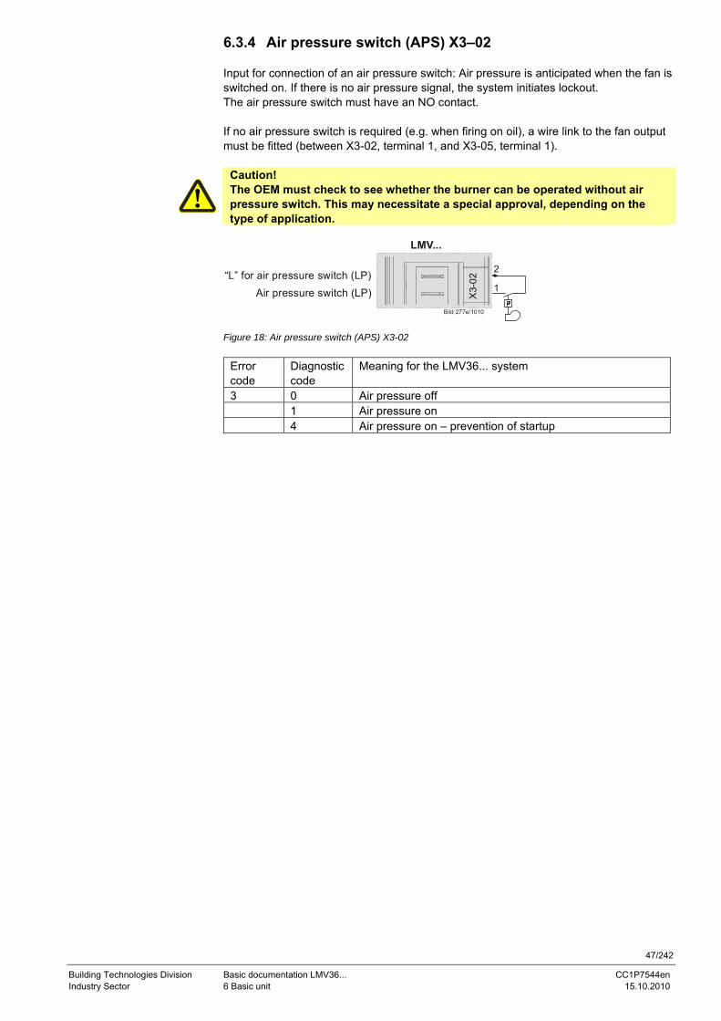
47/242
Building Technologies Division Basic documentation LMV36... CC1P7544en Industry Sector 6 Basic unit 15.10.2010
6.3.4 Air pressure switch (APS) X3–02 Input for connection of an air pressure switch: Air pressure is anticipated when the fan is switched on. If there is no air pressure signal, the system initiates lockout. The air pressure switch must have an NO contact. If no air pressure switch is required (e.g. when firing on oil), a wire link to the fan output must be fitted (between X3-02, terminal 1, and X3-05, terminal 1).
Caution! The OEM must check to see whether the burner can be operated without air pressure switch. This may necessitate a special approval, depending on the type of application.
LMV...
Bild 277e/1010
X3-
02
Air pressure switch (LP)“L” for air pressure switch (LP) 2
1
Figure 18: Air pressure switch (APS) X3-02
Error code
Diagnostic code
Meaning for the LMV36... system
3 0 Air pressure off 1 Air pressure on 4 Air pressure on – prevention of startup
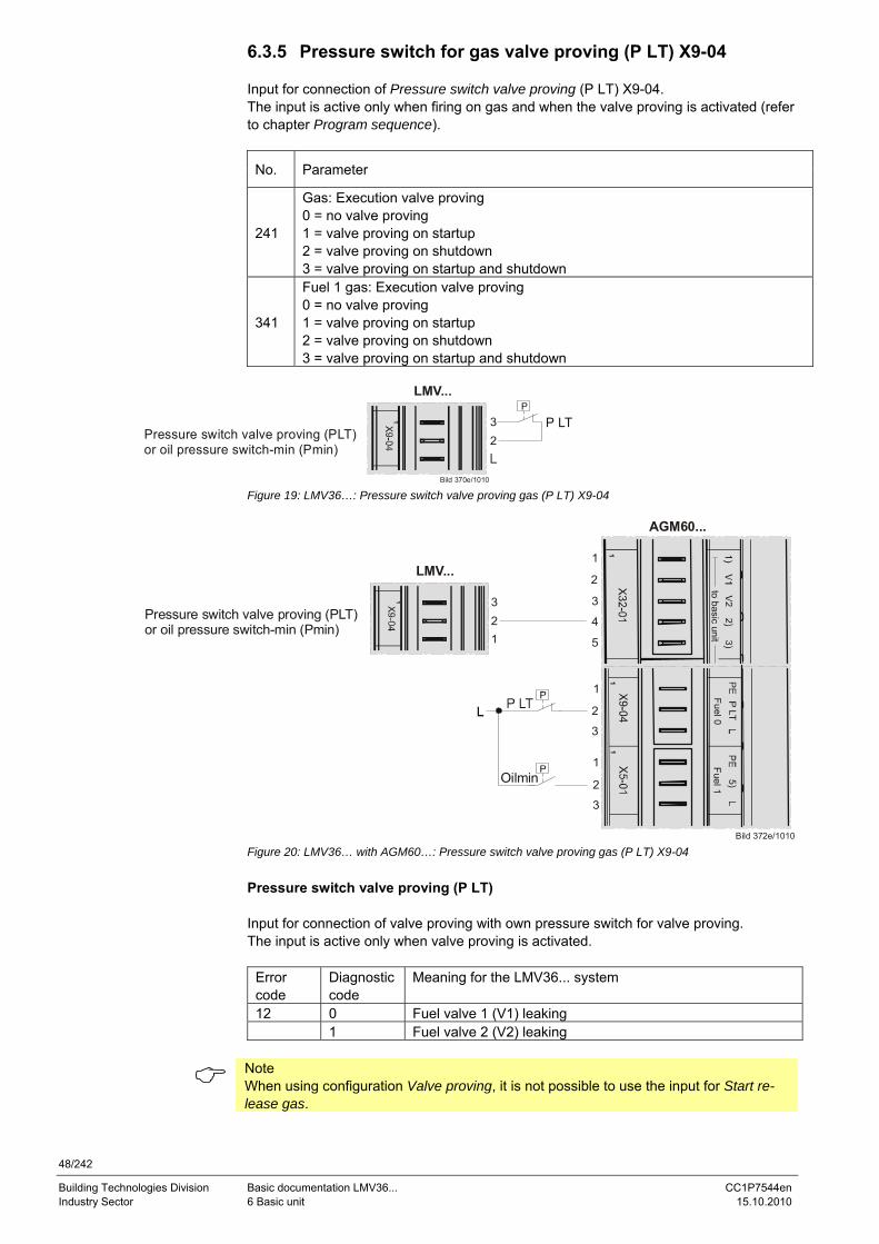
48/242
Building Technologies Division Basic documentation LMV36... CC1P7544en Industry Sector 6 Basic unit 15.10.2010
6.3.5 Pressure switch for gas valve proving (P LT) X9-04 Input for connection of Pressure switch valve proving (P LT) X9-04. The input is active only when firing on gas and when the valve proving is activated (refer to chapter Program sequence).
No. Parameter
241
Gas: Execution valve proving 0 = no valve proving 1 = valve proving on startup 2 = valve proving on shutdown 3 = valve proving on startup and shutdown
341
Fuel 1 gas: Execution valve proving 0 = no valve proving 1 = valve proving on startup 2 = valve proving on shutdown 3 = valve proving on startup and shutdown
Pressure switch valve proving (PLT)or oil pressure switch-min (Pmin)
LMV...
Bild 370e/1010
32
1 P LT
Figure 19: LMV36…: Pressure switch valve proving gas (P LT) X9-04
Pressure switch valve proving (PLT)or oil pressure switch-min (Pmin)
LMV...
321
1
Bild 372e/1010
Oilmin
1
tobasic
unitFuel1
Fuel 0
11
1
2
3
4
5
3
2
1
3
2
1
AGM60...
Figure 20: LMV36… with AGM60…: Pressure switch valve proving gas (P LT) X9-04 Pressure switch valve proving (P LT) Input for connection of valve proving with own pressure switch for valve proving. The input is active only when valve proving is activated.
Error code
Diagnostic code
Meaning for the LMV36... system
12 0 Fuel valve 1 (V1) leaking 1 Fuel valve 2 (V2) leaking
Note When using configuration Valve proving, it is not possible to use the input for Start re-lease gas.
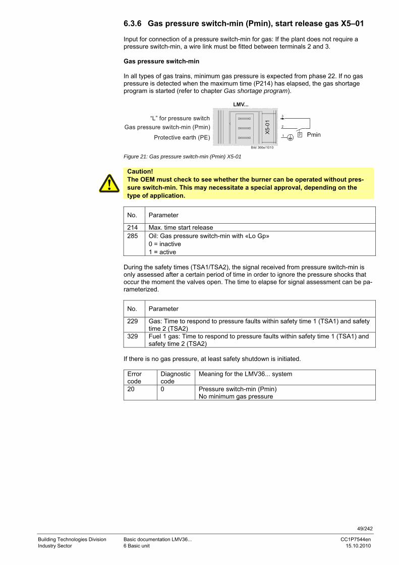
49/242
Building Technologies Division Basic documentation LMV36... CC1P7544en Industry Sector 6 Basic unit 15.10.2010
6.3.6 Gas pressure switch-min (Pmin), start release gas X5–01 Input for connection of a pressure switch-min for gas: If the plant does not require a pressure switch-min, a wire link must be fitted between terminals 2 and 3. Gas pressure switch-min In all types of gas trains, minimum gas pressure is expected from phase 22. If no gas pressure is detected when the maximum time (P214) has elapsed, the gas shortage program is started (refer to chapter Gas shortage program).
LMV...
Bild 366e/1010
X5-
01
Protective earth (PE)
Gas pressure switch-min (Pmin)“L” for pressure switch
Figure 21: Gas pressure switch-min (Pmin) X5-01
Caution! The OEM must check to see whether the burner can be operated without pres-sure switch-min. This may necessitate a special approval, depending on the type of application.
No. Parameter
214 Max. time start release 285 Oil: Gas pressure switch-min with «Lo Gp»
0 = inactive 1 = active
During the safety times (TSA1/TSA2), the signal received from pressure switch-min is only assessed after a certain period of time in order to ignore the pressure shocks that occur the moment the valves open. The time to elapse for signal assessment can be pa-rameterized.
No. Parameter
229 Gas: Time to respond to pressure faults within safety time 1 (TSA1) and safety time 2 (TSA2)
329 Fuel 1 gas: Time to respond to pressure faults within safety time 1 (TSA1) and safety time 2 (TSA2)
If there is no gas pressure, at least safety shutdown is initiated.
Error code
Diagnostic code
Meaning for the LMV36... system
20 0 Pressure switch-min (Pmin) No minimum gas pressure
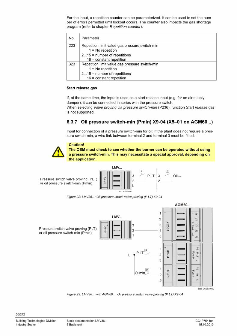
50/242
Building Technologies Division Basic documentation LMV36... CC1P7544en Industry Sector 6 Basic unit 15.10.2010
For the input, a repetition counter can be parameterized. It can be used to set the num-ber of errors permitted until lockout occurs. The counter also impacts the gas shortage program (refer to chapter Repetition counter).
No. Parameter
223 Repetition limit value gas pressure switch-min 1 = No repetition 2...15 = number of repetitions 16 = constant repetition
323 Repetition limit value gas pressure switch-min 1 = No repetition 2...15 = number of repetitions 16 = constant repetition
Start release gas If, at the same time, the input is used as a start release input (e.g. for an air supply damper), it can be connected in series with the pressure switch. When selecting Valve proving via pressure switch-min (P236), function Start release gas is not supported. 6.3.7 Oil pressure switch-min (Pmin) X9-04 (X5–01 on AGM60...) Input for connection of a pressure switch-min for oil: If the plant does not require a pres-sure switch-min, a wire link between terminal 2 and terminal 3 must be fitted.
Caution! The OEM must check to see whether the burner can be operated without using a pressure switch-min. This may necessitate a special approval, depending on the application.
Pressure switch valve proving (PLT)or oil pressure switch-min (Pmin)
LMV...
Bild 371e/1010
32
1 P LT 32
Oilmin
Figure 22: LMV36...: Oil pressure switch valve proving (P LT) X9-04
Pressure switch valve proving (PLT)or oil pressure switch-min (Pmin)
LMV...
321
1
Bild 369e/1010
Oilmin
1
tobasic
unitFuel1
Fuel0
11
1
2
3
4
5
3
2
1
3
2
1
AGM60...
Figure 23: LMV36... with AGM60...: Oil pressure switch valve proving (P LT) X9-04
51/242
Building Technologies Division Basic documentation LMV36... CC1P7544en Industry Sector 6 Basic unit 15.10.2010
Oil pressure switch-min In all types of oil train, the minimum oil pressure is expected from phase 38. If no oil pressure is detected when the maximum time (P217) has elapsed or if, subsequently, the oil pressure drops, the system initiates lockout.
No. Parameter
217 Max. Waiting time for detection of detector or pressure signal (e.g. homerun, preignition «Lo»)
Error code
Diagnostic code
Meaning for the LMV36... system
20 0 Pressure switch-min (Pmin) No min. oil pressure
During the safety times (TSA1/TSA2), the signal from pressure switch-min is only as-sessed after a certain period of time in order to ignore the pressure shocks that occur the moment the valves open. The time to elapse for signal assessment can be param-eterized.
No. Parameter
269 Oil: Time to respond to pressure faults within safety time 1 (TSA1) and safety time 2 (TSA2)
369 Fuel 1 oil: Time to respond to pressure faults within safety time 1 (TSA1) and safety time 2 (TSA2)
6.3.8 Setting the time for checking the pressure switch For oil pressure switch-min, the point in time from which the check is made can be set via parameter 276 (active from phase 38, or from safety time (TSA)).
No. Parameter
276 Oil: Pressure switch-min input 0 = inactive 1 = active from phase 38 2 = active from safety time (TSA)
376 Fuel 1 Oil: Pressure switch-min input 0 = inactive 1 = active from phase 38 2 = active from safety time (TSA)
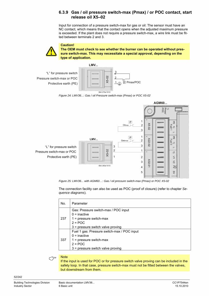
52/242
Building Technologies Division Basic documentation LMV36... CC1P7544en Industry Sector 6 Basic unit 15.10.2010
6.3.9 Gas / oil pressure switch-max (Pmax) / or POC contact, start release oil X5–02
Input for connection of a pressure switch-max for gas or oil: The sensor must have an NC contact, which means that the contact opens when the adjusted maximum pressure is exceeded. If the plant does not require a pressure switch-max, a wire link must be fit-ted between terminals 2 and 3.
Caution! The OEM must check to see whether the burner can be operated without pres-sure switch-max. This may necessitate a special approval, depending on the type of application.
LMV...
Bild 279e/1010
X5-
02
Pmax/POCProtective earth (PE)Pressure switch-max or POC
“L” for pressure switch
Figure 24: LMV36...: Gas / oil Pressure switch-max (Pmax) or POC X5-02
LMV...
Bild 280e/1010
X5-
02
Protective earth (PE)Pressure switch-max or POC
“L” for pressure switch
AGM60...
V3
OilmaxP
GasmaxP
32
1
12
3
12
3
1
2
3
4
5
Figure 25: LMV36... with AGM60…: Gas / oil pressure switch-max (Pmax) or POC X5-02 The connection facility can also be used as POC (proof of closure) (refer to chapter Se-quence diagrams).
No. Parameter
237
Gas: Pressure switch-max / POC input 0 = inactive 1 = pressure switch-max 2 = POC 3 = pressure switch valve proving
337
Fuel 1 gas: Pressure switch-max / POC input 0 = inactive 1 = pressure switch-max 2 = POC 3 = pressure switch valve proving
Note If the input is used for POC or for pressure switch valve proving can be included in the safety loop. In that case, pressure switch-max must not be fitted between the valves, but downstream from them.
53/242
Building Technologies Division Basic documentation LMV36... CC1P7544en Industry Sector 6 Basic unit 15.10.2010
Gas pressure switch-max In all types of gas trains, the maximum gas pressure is monitored from phase 40. If the maximum gas pressure is exceeded, the system initiates lockout.
Error code
Diagnostic code
Meaning for the LMV36... system
14 0 POC open 1 POC closed 21 0 Pressure switch-max (Pmax): Max. gas pressure exceeded
During the safety times (TSA1 / TSA2), the signal from pressure switch-max is only as-sessed after a certain period time has elapsed in order to ignore the pressure shocks that occur the moment the valves open.
No. Parameter
229 Gas: Time to respond to pressure faults within safety time 1 (TSA1) and safety time 2 (TSA2)
329 Fuel 1 gas: Time to respond to pressure faults within safety time 1 (TSA1) and safety time 2 (TSA2)
54/242
Building Technologies Division Basic documentation LMV36... CC1P7544en Industry Sector 6 Basic unit 15.10.2010
Pressure switch-max-oil In all types of oil trains, the maximum oil pressure is monitored from phase 22. If the maximum oil pressure is exceeded after the maximum time (parameter 214) has elapsed, or during the subsequent phases, the system initiates lockout.
No. Parameter
214 Max. time start release
Error code
Diagnostic code
Meaning for the LMV36... system
14 0 POC open 1 POC closed 21 0 Pressure switch-max (Pmax): Max. oil pressure exceeded
During the safety times (TSA1 / TSA2), the signal from pressure switch-max is only as-sessed after a certain period of time has elapsed to ignore the pressure shocks that oc-cur the moment the valves open.
No. Parameter
269 Oil: Time to respond to pressure faults within safety time 1 (TSA1) and safety time 2 (TSA2)
369 Fuel 1 oil: Time to respond to pressure faults within safety time 1 (TSA1) and safety time 2 (TSA2)
The terminal can also be used for POC (Proof of Closure) (refer to chapter Sequence diagrams).
No. Parameter
277
Oil: Pressure switch-max / POC input 0 = inactive 1 = pressure switch-max 2 = POC
377
Fuel 1 oil: Pressure switch-max / POC input 0 = inactive 1 = pressure switch-max 2 = POC
Note If the input is used for POC, pressure switch-max can be included in the safety loop. In that case, pressure switch-max must not be fitted between the valves, but after them.
Start release oil If the input is simultaneously used as a start release input (e.g. for an air supply damper), the latter can be connected in series with the pressure switch. If the input is parameterized for POC, it cannot be used as a start release input.
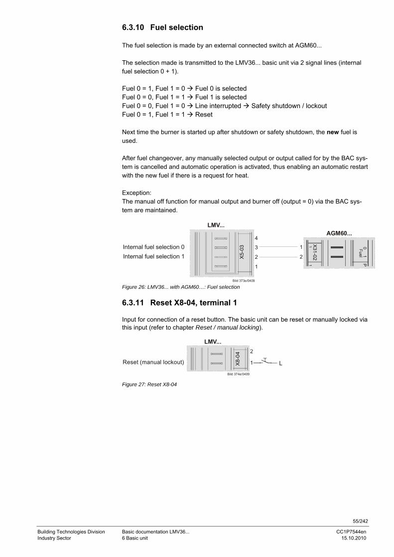
55/242
Building Technologies Division Basic documentation LMV36... CC1P7544en Industry Sector 6 Basic unit 15.10.2010
6.3.10 Fuel selection The fuel selection is made by an external connected switch at AGM60... The selection made is transmitted to the LMV36... basic unit via 2 signal lines (internal fuel selection 0 + 1). Fuel 0 = 1, Fuel 1 = 0 Fuel 0 is selected Fuel 0 = 0, Fuel 1 = 1 Fuel 1 is selected Fuel 0 = 0, Fuel 1 = 0 Line interrupted Safety shutdown / lockout Fuel 0 = 1, Fuel 1 = 1 Reset Next time the burner is started up after shutdown or safety shutdown, the new fuel is used. After fuel changeover, any manually selected output or output called for by the BAC sys-tem is cancelled and automatic operation is activated, thus enabling an automatic restart with the new fuel if there is a request for heat. Exception: The manual off function for manual output and burner off (output = 0) via the BAC sys-tem are maintained.
Bild 373e/0409
AGM60...
Internal fuel selection 1Internal fuel selection 0
X31-02
01
P
LMV...
X5-0
34
3
2
1
1
2
Figure 26: LMV36... with AGM60…: Fuel selection 6.3.11 Reset X8-04, terminal 1 Input for connection of a reset button. The basic unit can be reset or manually locked via this input (refer to chapter Reset / manual locking).
LMV...
Bild 374e/0409
X8-0
4
Reset (manual lockout) L
Figure 27: Reset X8-04
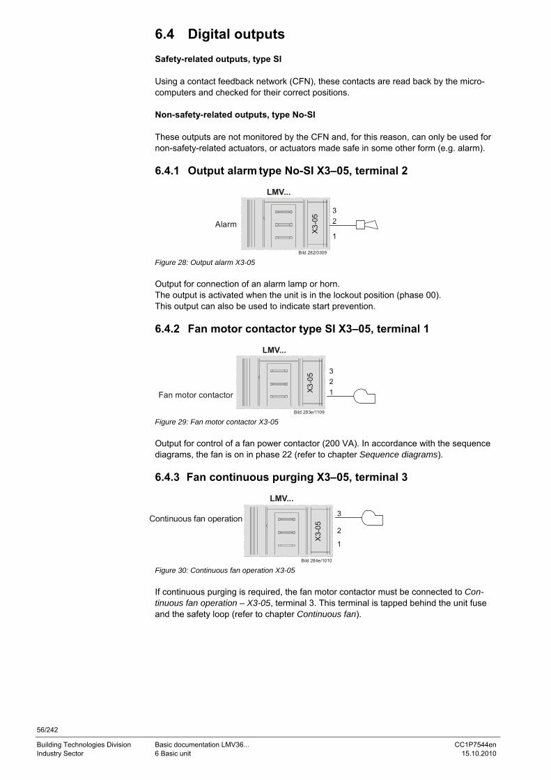
56/242
Building Technologies Division Basic documentation LMV36... CC1P7544en Industry Sector 6 Basic unit 15.10.2010
6.4 Digital outputs Safety-related outputs, type SI Using a contact feedback network (CFN), these contacts are read back by the micro-computers and checked for their correct positions. Non-safety-related outputs, type No-SI These outputs are not monitored by the CFN and, for this reason, can only be used for non-safety-related actuators, or actuators made safe in some other form (e.g. alarm). 6.4.1 Output alarm type No-SI X3–05, terminal 2
LMV...
Bild 282/0309
X3-
05Alarm
Figure 28: Output alarm X3-05 Output for connection of an alarm lamp or horn. The output is activated when the unit is in the lockout position (phase 00). This output can also be used to indicate start prevention. 6.4.2 Fan motor contactor type SI X3–05, terminal 1
LMV...
Bild 283e/1109
X3-
05
Fan motor contactor
Figure 29: Fan motor contactor X3-05 Output for control of a fan power contactor (200 VA). In accordance with the sequence diagrams, the fan is on in phase 22 (refer to chapter Sequence diagrams). 6.4.3 Fan continuous purging X3–05, terminal 3
LMV...
Bild 284e/1010
X3-
05
Continuous fan operation
Figure 30: Continuous fan operation X3-05 If continuous purging is required, the fan motor contactor must be connected to Con-tinuous fan operation – X3-05, terminal 3. This terminal is tapped behind the unit fuse and the safety loop (refer to chapter Continuous fan).
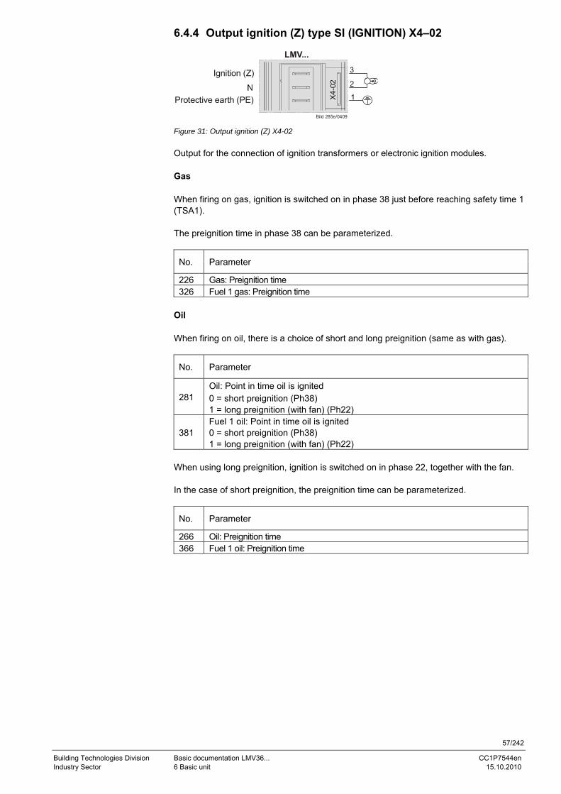
57/242
Building Technologies Division Basic documentation LMV36... CC1P7544en Industry Sector 6 Basic unit 15.10.2010
6.4.4 Output ignition (Z) type SI (IGNITION) X4–02
LMV...
Bild 285e/0409
X4-
02
Protective earth (PE)
Ignition (Z)
Figure 31: Output ignition (Z) X4-02 Output for the connection of ignition transformers or electronic ignition modules. Gas When firing on gas, ignition is switched on in phase 38 just before reaching safety time 1 (TSA1). The preignition time in phase 38 can be parameterized.
No. Parameter
226 Gas: Preignition time 326 Fuel 1 gas: Preignition time
Oil When firing on oil, there is a choice of short and long preignition (same as with gas).
No. Parameter
281 Oil: Point in time oil is ignited 0 = short preignition (Ph38) 1 = long preignition (with fan) (Ph22)
381 Fuel 1 oil: Point in time oil is ignited 0 = short preignition (Ph38) 1 = long preignition (with fan) (Ph22)
When using long preignition, ignition is switched on in phase 22, together with the fan. In the case of short preignition, the preignition time can be parameterized.
No. Parameter
266 Oil: Preignition time 366 Fuel 1 oil: Preignition time
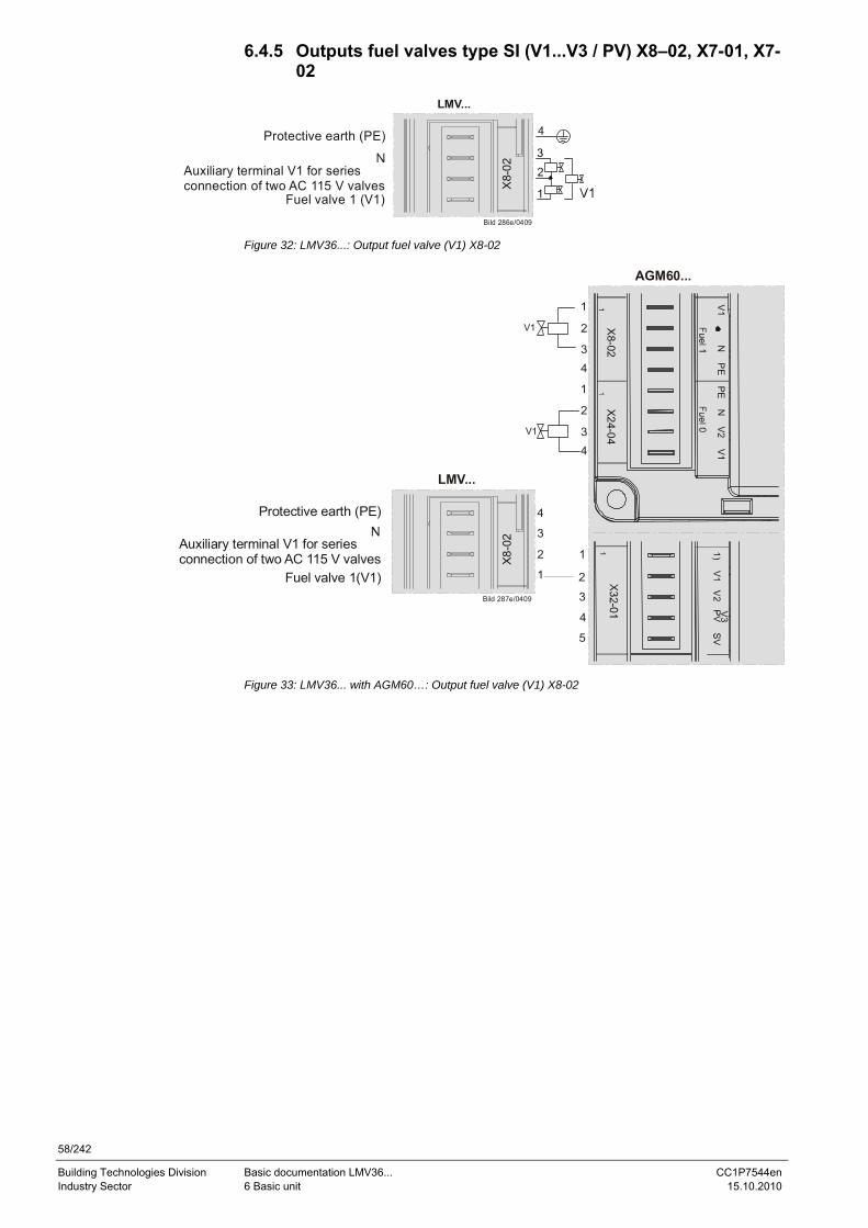
58/242
Building Technologies Division Basic documentation LMV36... CC1P7544en Industry Sector 6 Basic unit 15.10.2010
6.4.5 Outputs fuel valves type SI (V1...V3 / PV) X8–02, X7-01, X7-02
LMV...
Bild 286e/0409
X8-
02
Fuel valve 1 (V1)
Auxiliary terminal V1 for seriesconnection of two AC 115 V valves
Protective earth (PE)
Figure 32: LMV36...: Output fuel valve (V1) X8-02
LMV...
Bild 287e/0409
X8-0
2
Fuel valve 1(V1)
Auxiliary terminal V1 for seriesconnection of two AC 115 V valves
Protective earth (PE)
AGM60...
V3
X8-02
X24-04
V1 N P
EPE
NV2
V1
V1
V1
1
2
34
1
2
34
1
2
3
4
5
4
3
2
1
Figure 33: LMV36... with AGM60…: Output fuel valve (V1) X8-02
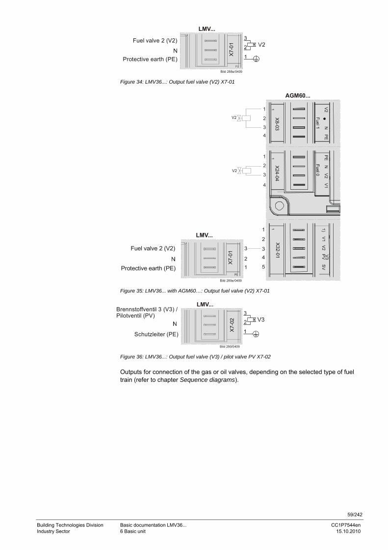
59/242
Building Technologies Division Basic documentation LMV36... CC1P7544en Industry Sector 6 Basic unit 15.10.2010
LMV...
Bild 288e/0409
X7-
01
Fuel valve 2 (V2)
Protective earth (PE)
Figure 34: LMV36...: Output fuel valve (V2) X7-01
LMV...
Bild 289e/0409
X7-
01
Fuel valve 2 (V2)
Protective earth (PE)
AGM60...
V3
X8-03
V2 N
PE
X24-04
PE
NV
2V
1
V2
V2
1
2
3
4
1
2
3
4
1
2
34
5
3
21
Figure 35: LMV36... with AGM60…: Output fuel valve (V2) X7-01
LMV...
Bild 290/0409
X7-
02
Brennstoffventil 3 (V3) /
Schutzleiter (PE)
Pilotventil (PV)
Figure 36: LMV36...: Output fuel valve (V3) / pilot valve PV X7-02 Outputs for connection of the gas or oil valves, depending on the selected type of fuel train (refer to chapter Sequence diagrams).
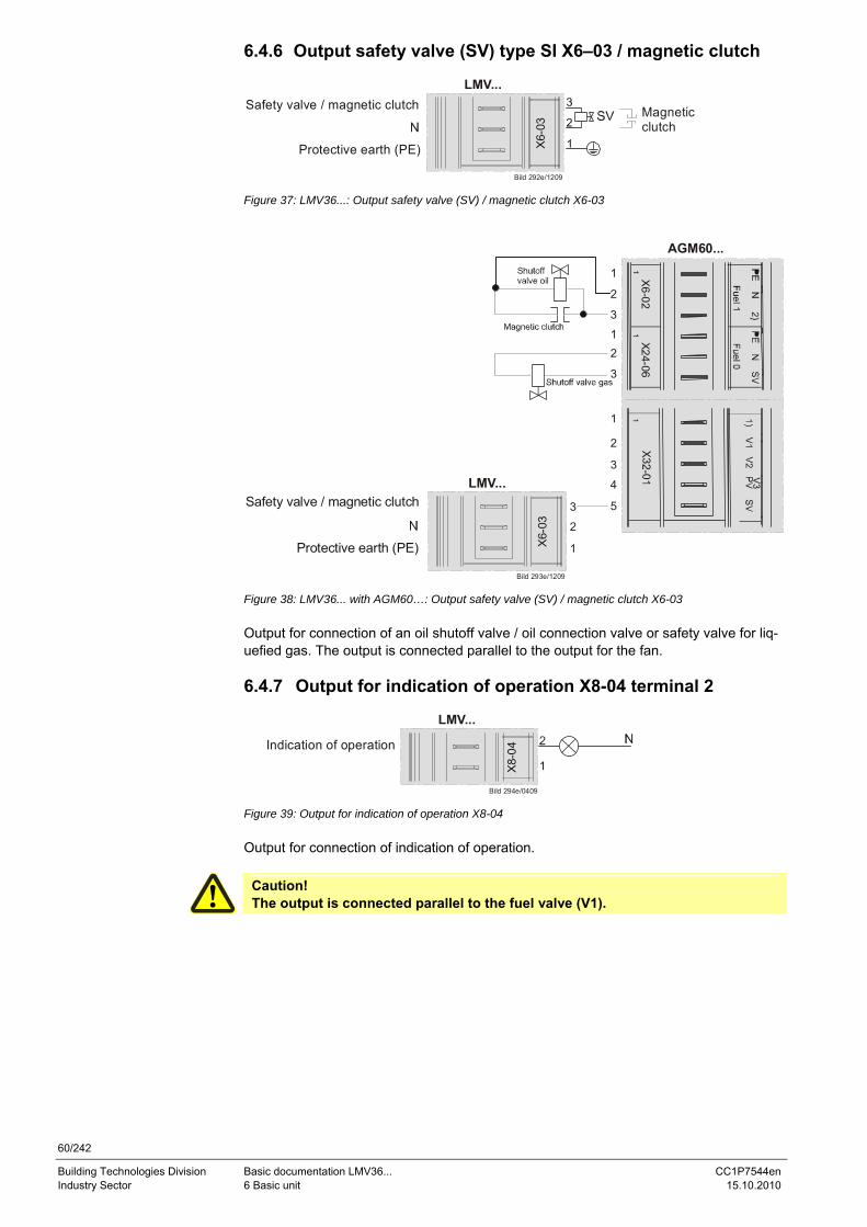
60/242
Building Technologies Division Basic documentation LMV36... CC1P7544en Industry Sector 6 Basic unit 15.10.2010
6.4.6 Output safety valve (SV) type SI X6–03 / magnetic clutch
LMV...
Bild 292e/1209
X6-
03
Safety valve / magnetic clutch
Protective earth (PE)
Magneticclutch
Figure 37: LMV36...: Output safety valve (SV) / magnetic clutch X6-03
LMV...
Bild 293e/1209
X6-
03
Safety valve / magnetic clutch
Protective earth (PE)
AGM60...
V3
X6-02 X24-06
1
2
3
12
3
1
2
3
4
53
2
1
Figure 38: LMV36... with AGM60…: Output safety valve (SV) / magnetic clutch X6-03 Output for connection of an oil shutoff valve / oil connection valve or safety valve for liq-uefied gas. The output is connected parallel to the output for the fan. 6.4.7 Output for indication of operation X8-04 terminal 2
LMV...
Bild 294e/0409
X8-0
4Indication of operation
Figure 39: Output for indication of operation X8-04 Output for connection of indication of operation.
Caution! The output is connected parallel to the fuel valve (V1).
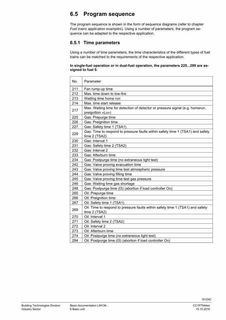
61/242
Building Technologies Division Basic documentation LMV36... CC1P7544en Industry Sector 6 Basic unit 15.10.2010
6.5 Program sequence The program sequence is shown in the form of sequence diagrams (refer to chapter Fuel trains application examples). Using a number of parameters, the program se-quence can be adapted to the respective application. 6.5.1 Time parameters Using a number of time parameters, the time characteristics of the different types of fuel trains can be matched to the requirements of the respective application. In single-fuel operation or in dual-fuel operation, the parameters 225...299 are as-signed to fuel 0.
No. Parameter
211 Fan rump-up time 212 Max. time down to low-fire 213 Waiting time home run 214 Max. time start release
217 Max. Waiting time for detection of detector or pressure signal (e.g. homerun, preignition «Lo»)
225 Gas: Prepurge time 226 Gas: Preignition time 227 Gas: Safety time 1 (TSA1)
229 Gas: Time to respond to pressure faults within safety time 1 (TSA1) and safety time 2 (TSA2)
230 Gas: Interval 1 231 Gas: Safety time 2 (TSA2) 232 Gas: Interval 2 233 Gas: Afterburn time 234 Gas: Postpurge time (no extraneous light test) 242 Gas: Valve proving evacuation time 243 Gas: Valve proving time test atmospheric pressure 244 Gas: Valve proving filling time 245 Gas: Valve proving time test gas pressure 246 Gas: Waiting time gas shortage 248 Gas: Postpurge time (t3) (abortion if load controller On) 265 Oil: Prepurge time 266 Oil: Preignition time 267 Oil: Safety time 1 (TSA1)
269 Oil: Time to respond to pressure faults within safety time 1 (TSA1) and safety time 2 (TSA2)
270 Oil: Interval 1 271 Oil: Safety time 2 (TSA2) 272 Oil: Interval 2 273 Oil: Afterburn time 274 Oil: Postpurge time (no extraneous light test) 284 Oil: Postpurge time (t3) (abortion if load controller On)
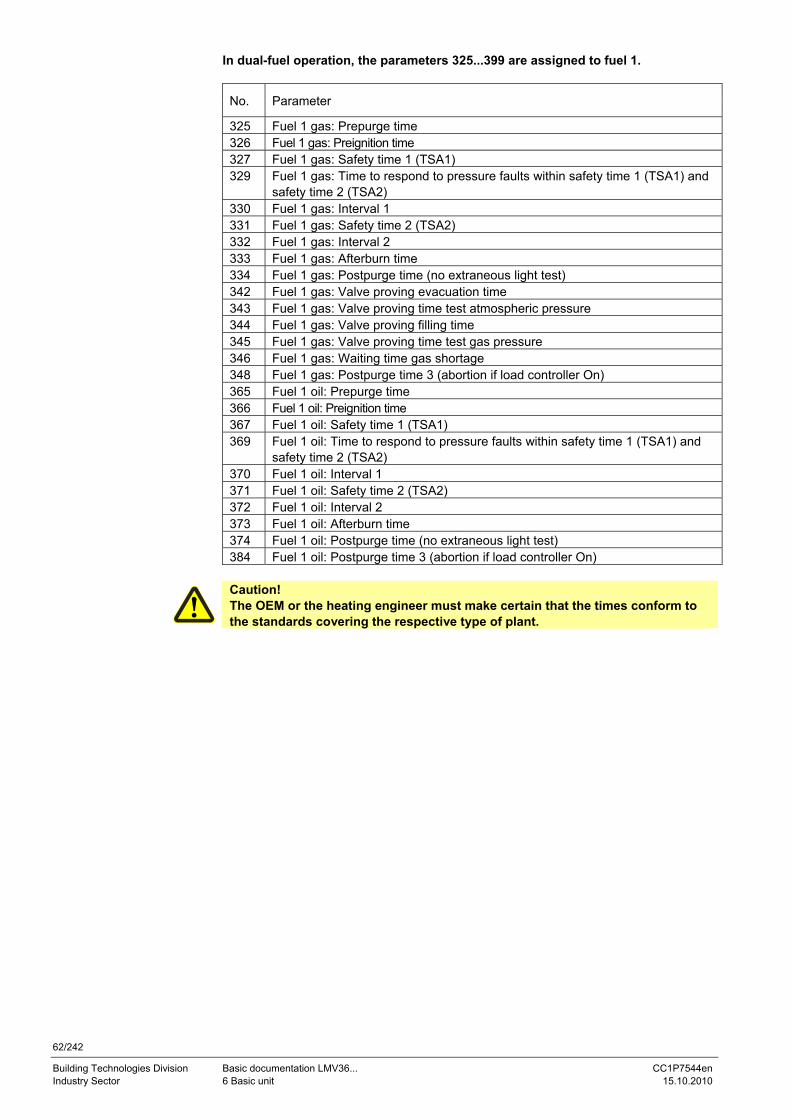
62/242
Building Technologies Division Basic documentation LMV36... CC1P7544en Industry Sector 6 Basic unit 15.10.2010
In dual-fuel operation, the parameters 325...399 are assigned to fuel 1.
No. Parameter
325 Fuel 1 gas: Prepurge time 326 Fuel 1 gas: Preignition time 327 Fuel 1 gas: Safety time 1 (TSA1) 329 Fuel 1 gas: Time to respond to pressure faults within safety time 1 (TSA1) and
safety time 2 (TSA2) 330 Fuel 1 gas: Interval 1 331 Fuel 1 gas: Safety time 2 (TSA2) 332 Fuel 1 gas: Interval 2 333 Fuel 1 gas: Afterburn time 334 Fuel 1 gas: Postpurge time (no extraneous light test) 342 Fuel 1 gas: Valve proving evacuation time 343 Fuel 1 gas: Valve proving time test atmospheric pressure 344 Fuel 1 gas: Valve proving filling time 345 Fuel 1 gas: Valve proving time test gas pressure 346 Fuel 1 gas: Waiting time gas shortage 348 Fuel 1 gas: Postpurge time 3 (abortion if load controller On) 365 Fuel 1 oil: Prepurge time 366 Fuel 1 oil: Preignition time 367 Fuel 1 oil: Safety time 1 (TSA1) 369 Fuel 1 oil: Time to respond to pressure faults within safety time 1 (TSA1) and
safety time 2 (TSA2) 370 Fuel 1 oil: Interval 1 371 Fuel 1 oil: Safety time 2 (TSA2) 372 Fuel 1 oil: Interval 2 373 Fuel 1 oil: Afterburn time 374 Fuel 1 oil: Postpurge time (no extraneous light test) 384 Fuel 1 oil: Postpurge time 3 (abortion if load controller On)
Caution! The OEM or the heating engineer must make certain that the times conform to the standards covering the respective type of plant.
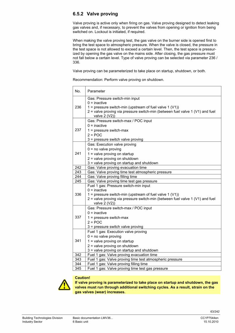
63/242
Building Technologies Division Basic documentation LMV36... CC1P7544en Industry Sector 6 Basic unit 15.10.2010
6.5.2 Valve proving Valve proving is active only when firing on gas. Valve proving designed to detect leaking gas valves and, if necessary, to prevent the valves from opening or ignition from being switched on. Lockout is initiated, if required. When making the valve proving test, the gas valve on the burner side is opened first to bring the test space to atmospheric pressure. When the valve is closed, the pressure in the test space is not allowed to exceed a certain level. Then, the test space is pressur-ized by opening the gas valve on the mains side. After closing, the gas pressure must not fall below a certain level. Type of valve proving can be selected via parameter 236 / 336. Valve proving can be parameterized to take place on startup, shutdown, or both. Recommendation: Perform valve proving on shutdown.
No. Parameter
236
Gas: Pressure switch-min input 0 = inactive 1 = pressure switch-min (upstream of fuel valve 1 (V1)) 2 = valve proving via pressure switch-min (between fuel valve 1 (V1) and fuel valve 2 (V2))
237
Gas: Pressure switch-max / POC input 0 = inactive 1 = pressure switch-max 2 = POC 3 = pressure switch valve proving
241
Gas: Execution valve proving 0 = no valve proving 1 = valve proving on startup 2 = valve proving on shutdown 3 = valve proving on startup and shutdown
242 Gas: Valve proving evacuation time 243 Gas: Valve proving time test atmospheric pressure 244 Gas: Valve proving filling time 245 Gas: Valve proving time test gas pressure
336
Fuel 1 gas: Pressure switch-min input 0 = inactive 1 = pressure switch-min (upstream of fuel valve 1 (V1)) 2 = valve proving via pressure switch-min (between fuel valve 1 (V1) and fuel valve 2 (V2))
337
Gas: Pressure switch-max / POC input 0 = inactive 1 = pressure switch-max 2 = POC 3 = pressure switch valve proving
341
Fuel 1 gas: Execution valve proving 0 = no valve proving 1 = valve proving on startup 2 = valve proving on shutdown 3 = valve proving on startup and shutdown
342 Fuel 1 gas: Valve proving evacuation time 343 Fuel 1 gas: Valve proving time test atmospheric pressure 344 Fuel 1 gas: Valve proving filling time 345 Fuel 1 gas: Valve proving time test gas pressure
Caution! If valve proving is parameterized to take place on startup and shutdown, the gas valves must run through additional switching cycles. As a result, strain on the gas valves (wear) increases.
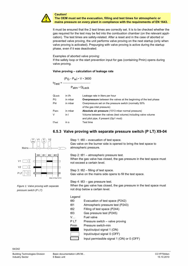
64/242
Building Technologies Division Basic documentation LMV36... CC1P7544en Industry Sector 6 Basic unit 15.10.2010
Caution! The OEM must set the evacuation, filling and test times for atmospheric or mains pressure on every plant in compliance with the requirements of EN 1643.
It must be ensured that the 2 test times are correctly set. It is to be checked whether the gas required for the test may be fed into the combustion chamber (on the relevant appli-cation). The test times are safety-related. After a reset and in the case of aborted or prevented valve proving, the unit performs valve proving on the next startup (only when valve proving is activated). Prepurging with valve proving is active during the startup phase, even if it was deactivated. Examples of aborted valve proving: If the safety loop or the start prevention input for gas (containing Pmin) opens during valve proving. Valve proving – calculation of leakage rate (PG - Pw) • V • 3600 tTest = ⎯⎯⎯⎯⎯⎯⎯⎯⎯
Patm • QLeck QLeck in l/h Leakage rate in liters per hour PG in mbar Overpressure between the valves at the beginning of the test phase PW in mbar Overpressure set on the pressure switch (normally 50% of the gas inlet pressure) Patm in mbar Absolute air pressure (1013 mbar normal pressure) V in l Volume between the valves (test volume) including valve volume and pilot pipe, if present (Gp1 mod) tTest in s Test time
6.5.3 Valve proving with separate pressure switch (P LT) X9-04
Step 1: t80 – evacuation of test space. Gas valve on the burner side is opened to bring the test space to atmospheric pressure. Step 2: t81 – atmospheric pressure test. When the gas valve has closed, the gas pressure in the test space must not exceed a certain level. Step 3: t82 – filling of test space. Gas valve on the mains side opens to fill the test space. Step 4: t83 – gas pressure test. When the gas valve has closed, the gas pressure in the test space must not drop below a certain level. Legend t80 Evacuation of test space (P242) t81 Atmospheric pressure test (P243) t82 Filling of test space (P244) t83 Gas pressure test (P245) V… Fuel valve P LT Pressure switch – valve proving Pmin Pressure switch-min
Input/output signal 1 (ON)
Input/output signal 0 (OFF)
P LT
PLT
Bild 410e/1010
Pmin
Figure 1: Valve proving with separate pressure switch (P LT)
Input permissible signal 1 (ON) or 0 (OFF)
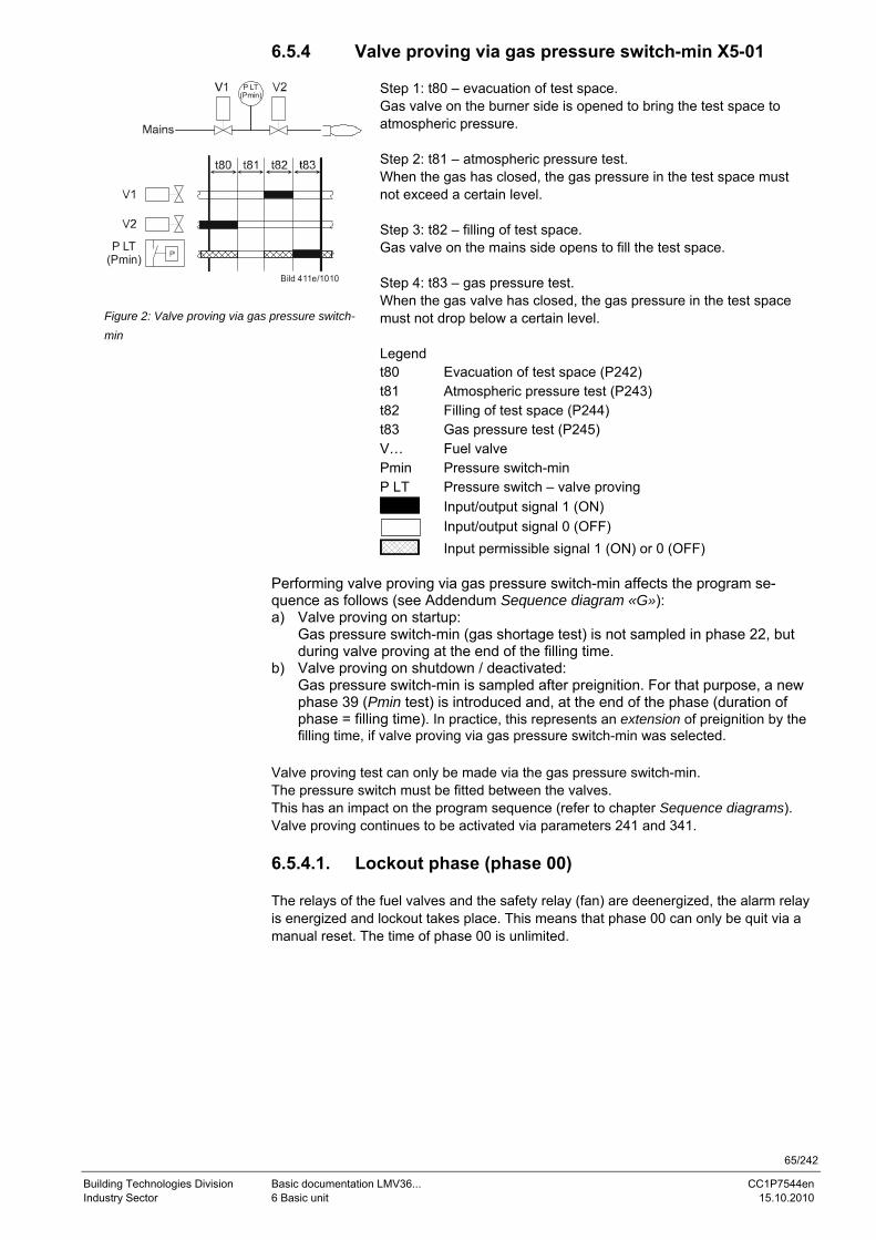
65/242
Building Technologies Division Basic documentation LMV36... CC1P7544en Industry Sector 6 Basic unit 15.10.2010
6.5.4 Valve proving via gas pressure switch-min X5-01
Step 1: t80 – evacuation of test space. Gas valve on the burner side is opened to bring the test space to atmospheric pressure. Step 2: t81 – atmospheric pressure test. When the gas has closed, the gas pressure in the test space must not exceed a certain level. Step 3: t82 – filling of test space. Gas valve on the mains side opens to fill the test space. Step 4: t83 – gas pressure test. When the gas valve has closed, the gas pressure in the test space must not drop below a certain level. Legend t80 Evacuation of test space (P242) t81 Atmospheric pressure test (P243) t82 Filling of test space (P244) t83 Gas pressure test (P245) V… Fuel valve Pmin Pressure switch-min P LT Pressure switch – valve proving
Input/output signal 1 (ON)
Input/output signal 0 (OFF)
Bild 411e/1010
P LT(Pmin)
P LT(Pmin)
Figure 2: Valve proving via gas pressure switch-min
Input permissible signal 1 (ON) or 0 (OFF) Performing valve proving via gas pressure switch-min affects the program se-quence as follows (see Addendum Sequence diagram «G»): a) Valve proving on startup:
Gas pressure switch-min (gas shortage test) is not sampled in phase 22, but during valve proving at the end of the filling time.
b) Valve proving on shutdown / deactivated: Gas pressure switch-min is sampled after preignition. For that purpose, a new phase 39 (Pmin test) is introduced and, at the end of the phase (duration of phase = filling time). In practice, this represents an extension of preignition by the filling time, if valve proving via gas pressure switch-min was selected.
Valve proving test can only be made via the gas pressure switch-min. The pressure switch must be fitted between the valves. This has an impact on the program sequence (refer to chapter Sequence diagrams). Valve proving continues to be activated via parameters 241 and 341. 6.5.4.1. Lockout phase (phase 00) The relays of the fuel valves and the safety relay (fan) are deenergized, the alarm relay is energized and lockout takes place. This means that phase 00 can only be quit via a manual reset. The time of phase 00 is unlimited.

66/242
Building Technologies Division Basic documentation LMV36... CC1P7544en Industry Sector 6 Basic unit 15.10.2010
6.5.4.2. Safety phase (phase 02) The safety phase is an intermediate phase which is completed prior to triggering lock-out. The relays of the fuel valves and the safety relay (fan) are deenergized, but lockout does not yet take place. The alarm relay is not yet activated. If possible or permitted, safety checks or repetition counter checks are made whose results decide on the transi-tion to Lockout phase or Standby. The duration of the safety phase is dynamic (depend-ing on the extent of testing), the maximum time being 30 seconds. This process is aimed primarily at avoiding unwanted lockouts, e.g. resulting from EMC problems.
67/242
Building Technologies Division Basic documentation LMV36... CC1P7544en Industry Sector 6 Basic unit 15.10.2010
6.5.5 Special functions during the program sequence 6.5.5.1. Reset / manual lockout The system can be manually locked by simultaneously pressing the Info button and any other button on the AZL2... This function enables the user to interlock the system from any operating level, that is, to trigger unalterable shutdown. Due to the system’s makeup, this facility does not constitute an Emergency OFF function. When making a reset, the following actions are carried out: • Alarm relay and fault display are switched off • The lockout position is cancelled • The unit makes a reset and then changes to standby The system can be reset in 3 different ways: 1. Reset on the AZL2... display and operating unit If the unit is in the lockout position, a reset can be made by pressing the Info button for 1…3 seconds. The function is available only when the unit is in the lockout position. Longer or shorter pushes on the button do not produce a reset so that the system main-tains the lockout position.
Error code
Diagnostic code
Meaning for the LMV36... system
167 2 Manual lockout by the AZL2...
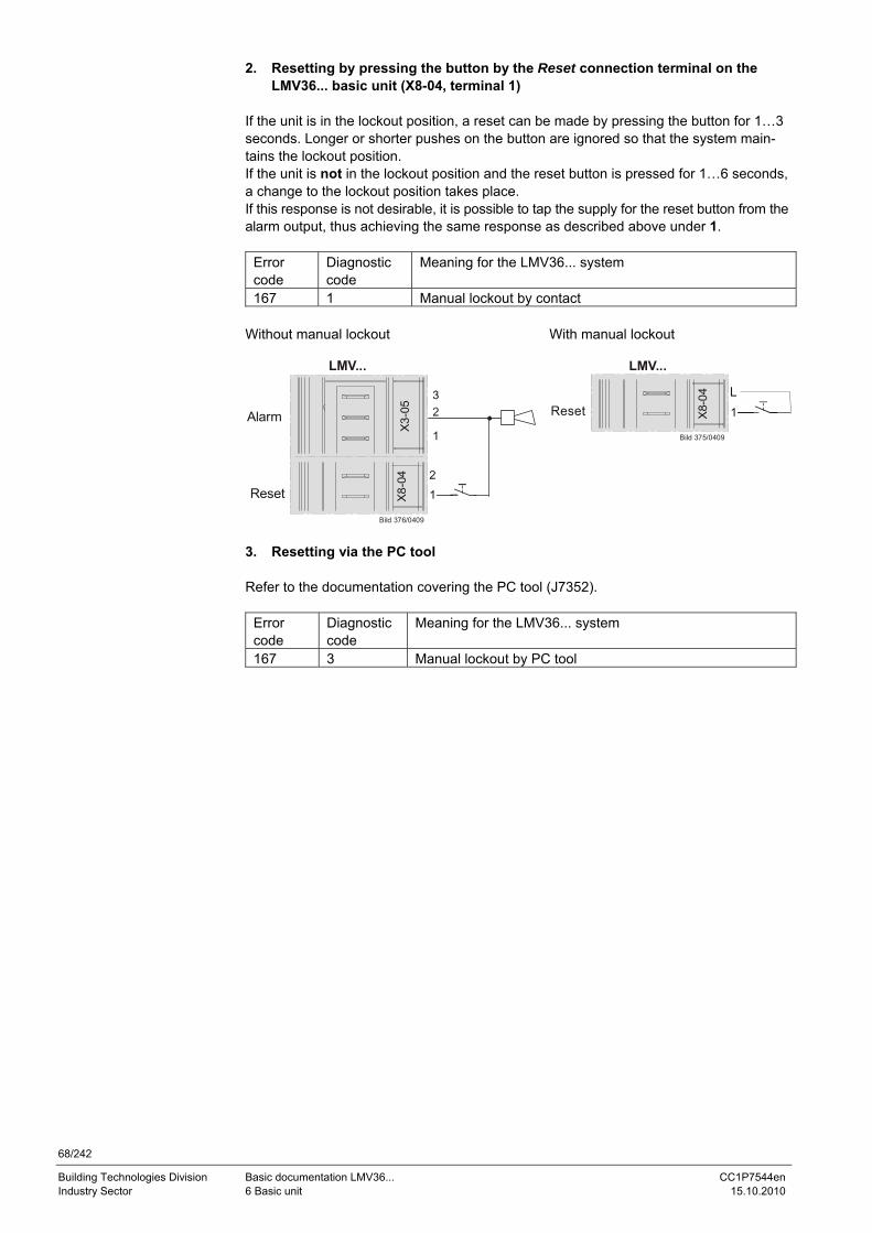
68/242
Building Technologies Division Basic documentation LMV36... CC1P7544en Industry Sector 6 Basic unit 15.10.2010
2. Resetting by pressing the button by the Reset connection terminal on the
LMV36... basic unit (X8-04, terminal 1) If the unit is in the lockout position, a reset can be made by pressing the button for 1…3 seconds. Longer or shorter pushes on the button are ignored so that the system main-tains the lockout position. If the unit is not in the lockout position and the reset button is pressed for 1…6 seconds, a change to the lockout position takes place. If this response is not desirable, it is possible to tap the supply for the reset button from the alarm output, thus achieving the same response as described above under 1.
Error code
Diagnostic code
Meaning for the LMV36... system
167 1 Manual lockout by contact Without manual lockout With manual lockout
Bild 376/0409
X8-
04
Reset2
LMV...
X3-
05Alarm
LMV...
Bild 375/0409
X8-
04
ResetL
3. Resetting via the PC tool Refer to the documentation covering the PC tool (J7352).
Error code
Diagnostic code
Meaning for the LMV36... system
167 3 Manual lockout by PC tool
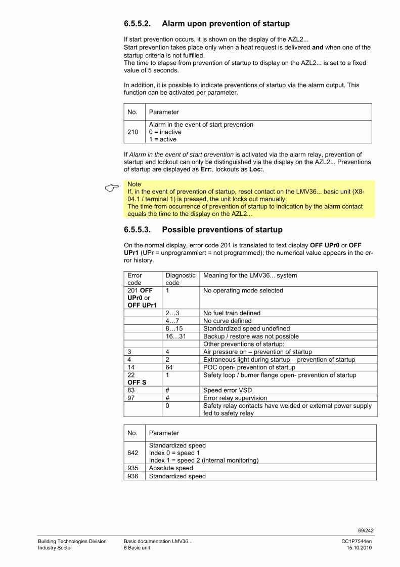
69/242
Building Technologies Division Basic documentation LMV36... CC1P7544en Industry Sector 6 Basic unit 15.10.2010
6.5.5.2. Alarm upon prevention of startup If start prevention occurs, it is shown on the display of the AZL2... Start prevention takes place only when a heat request is delivered and when one of the startup criteria is not fulfilled. The time to elapse from prevention of startup to display on the AZL2... is set to a fixed value of 5 seconds. In addition, it is possible to indicate preventions of startup via the alarm output. This function can be activated per parameter.
No. Parameter
210 Alarm in the event of start prevention 0 = inactive 1 = active
If Alarm in the event of start prevention is activated via the alarm relay, prevention of startup and lockout can only be distinguished via the display on the AZL2... Preventions of startup are displayed as Err:, lockouts as Loc:.
Note If, in the event of prevention of startup, reset contact on the LMV36... basic unit (X8-04.1 / terminal 1) is pressed, the unit locks out manually. The time from occurrence of prevention of startup to indication by the alarm contact equals the time to the display on the AZL2...
6.5.5.3. Possible preventions of startup On the normal display, error code 201 is translated to text display OFF UPr0 or OFF UPr1 (UPr = unprogrammiert = not programmed); the numerical value appears in the er-ror history.
Error code
Diagnostic code
Meaning for the LMV36... system
201 OFF UPr0 or OFF UPr1
1 No operating mode selected
2…3 No fuel train defined 4…7 No curve defined 8…15 Standardized speed undefined 16…31 Backup / restore was not possible Other preventions of startup: 3 4 Air pressure on – prevention of startup 4 2 Extraneous light during startup – prevention of startup 14 64 POC open- prevention of startup 22 OFF S
1 Safety loop / burner flange open- prevention of startup
83 # Speed error VSD 97 # Error relay supervision 0 Safety relay contacts have welded or external power supply
fed to safety relay
No. Parameter
642 Standardized speed Index 0 = speed 1 Index 1 = speed 2 (internal monitoring)
935 Absolute speed 936 Standardized speed
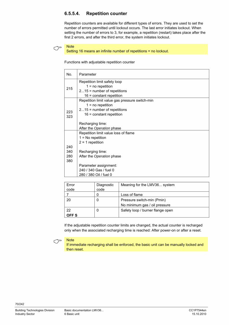
70/242
Building Technologies Division Basic documentation LMV36... CC1P7544en Industry Sector 6 Basic unit 15.10.2010
6.5.5.4. Repetition counter Repetition counters are available for different types of errors. They are used to set the number of errors permitted until lockout occurs. The last error initiates lockout. When setting the number of errors to 3, for example, a repetition (restart) takes place after the first 2 errors, and after the third error, the system initiates lockout.
Note Setting 16 means an infinite number of repetitions = no lockout.
Functions with adjustable repetition counter
No. Parameter
215
Repetition limit safety loop 1 = no repetition 2...15 = number of repetitions 16 = constant repetition
223 323
Repetition limit value gas pressure switch-min 1 = no repetition 2...15 = number of repetitions 16 = constant repetition Recharging time: After the Operation phase
240 340 280 380
Repetition limit value loss of flame 1 = No repetition 2 = 1 repetition Recharging time: After the Operation phase Parameter assignment: 240 / 340 Gas / fuel 0 280 / 380 Oil / fuel 0
Error code
Diagnostic code
Meaning for the LMV36... system
7 0 Loss of flame 20 0 Pressure switch-min (Pmin)
No minimum gas / oil pressure 22 OFF S
0 Safety loop / burner flange open
If the adjustable repetition counter limits are changed, the actual counter is recharged only when the associated recharging time is reached: After power-on or after a reset.
Note If immediate recharging shall be enforced, the basic unit can be manually locked and then reset.
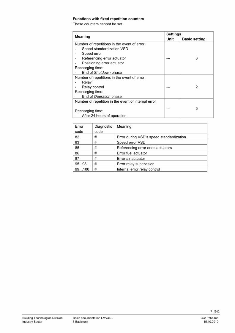
71/242
Building Technologies Division Basic documentation LMV36... CC1P7544en Industry Sector 6 Basic unit 15.10.2010
Functions with fixed repetition counters These counters cannot be set.
Settings Meaning Unit Basic setting Number of repetitions in the event of error: - Speed standardization VSD - Speed error - Referencing error actuator - Positioning error actuator Recharging time: - End of Shutdown phase
--- 3
Number of repetitions in the event of error: - Relay - Relay control Recharging time: - End of Operation phase
--- 2
Number of repetition in the event of internal error Recharging time: - After 24 hours of operation
--- 5
Error code
Diagnostic code
Meaning
82 # Error during VSD’s speed standardization 83 # Speed error VSD 85 # Referencing error ones actuators 86 # Error fuel actuator 87 # Error air actuator 95...98 # Error relay supervision 99…100 # Internal error relay control
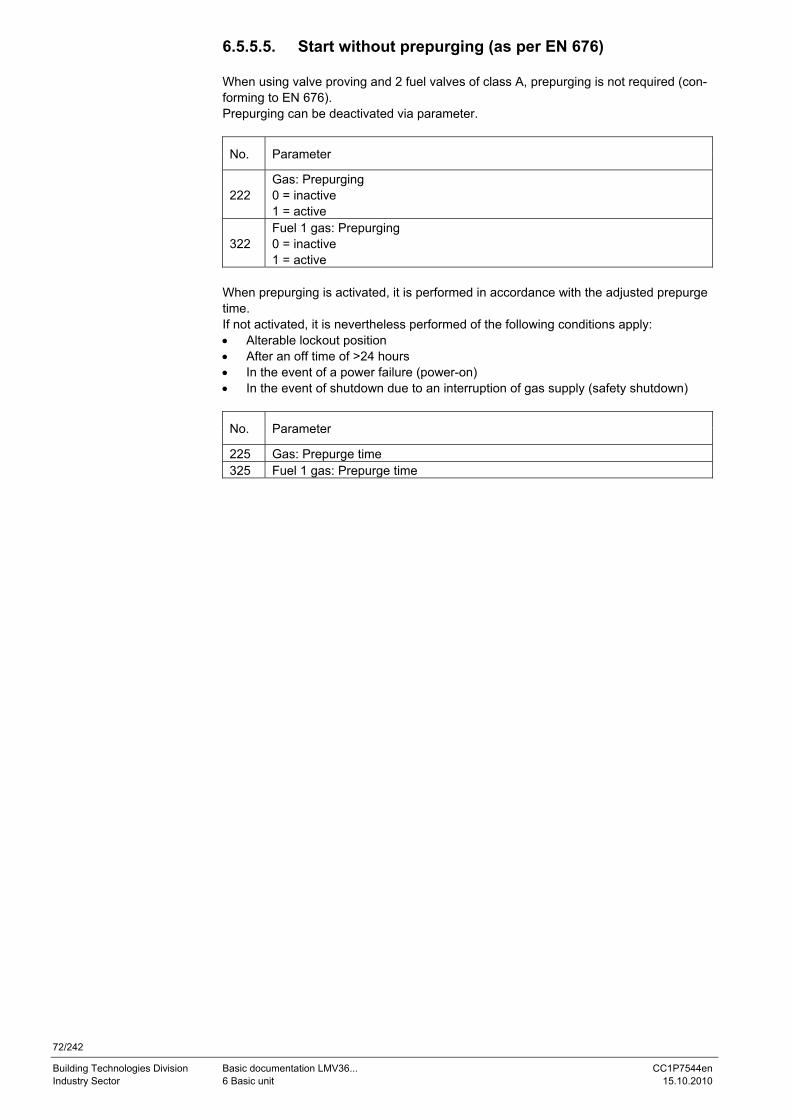
72/242
Building Technologies Division Basic documentation LMV36... CC1P7544en Industry Sector 6 Basic unit 15.10.2010
6.5.5.5. Start without prepurging (as per EN 676) When using valve proving and 2 fuel valves of class A, prepurging is not required (con-forming to EN 676). Prepurging can be deactivated via parameter.
No. Parameter
222 Gas: Prepurging 0 = inactive 1 = active
322 Fuel 1 gas: Prepurging 0 = inactive 1 = active
When prepurging is activated, it is performed in accordance with the adjusted prepurge time. If not activated, it is nevertheless performed of the following conditions apply: • Alterable lockout position • After an off time of >24 hours • In the event of a power failure (power-on) • In the event of shutdown due to an interruption of gas supply (safety shutdown)
No. Parameter
225 Gas: Prepurge time 325 Fuel 1 gas: Prepurge time
73/242
Building Technologies Division Basic documentation LMV36... CC1P7544en Industry Sector 6 Basic unit 15.10.2010
6.5.5.6. Gas shortage program Valve proving via gas pressure switch-min (P236 = 2) Since gas pressure switch-min is not located between the fuel valves, the gas shortage test cannot be made in phase 22. Therefore, when performing valve proving on startup, the gas shortage test is made at the end of the filling time (end of phase 82). With no valve proving on startup, the gas shortage test is made directly before safety time 1 is started (end of phase 39). Standard valve proving (P236 = 1) If the gas pressure is too low, startup is aborted in phase 22.
No. Parameter
246 Gas: Waiting time gas shortage 346 Fuel 1 gas: Waiting time gas shortage
If gas shortage occurs with the last of the parameterized number of start attempts, the system initiates lockout.
No. Parameter
223 Repetition limit value gas pressure switch-min 1 = no repetition 2...15 = number of repetitions 16 = constant repetition
323 Repetition limit value gas pressure switch-min 1 = no repetition 2...15 = number of repetitions 16 = constant repetition
In that case, the system makes with gas shortage program a selectable number of start attempts until lockout occurs. The waiting time from one start attempt to the next is dou-bled each time, starting from an adjustable waiting time.
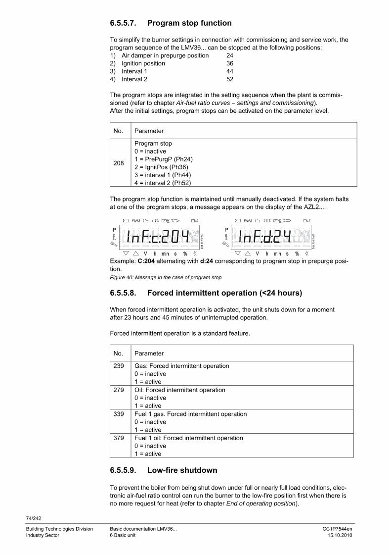
74/242
Building Technologies Division Basic documentation LMV36... CC1P7544en Industry Sector 6 Basic unit 15.10.2010
6.5.5.7. Program stop function To simplify the burner settings in connection with commissioning and service work, the program sequence of the LMV36... can be stopped at the following positions: 1) Air damper in prepurge position 24 2) Ignition position 36 3) Interval 1 44 4) Interval 2 52 The program stops are integrated in the setting sequence when the plant is commis-sioned (refer to chapter Air-fuel ratio curves – settings and commissioning). After the initial settings, program stops can be activated on the parameter level.
No. Parameter
208
Program stop 0 = inactive 1 = PrePurgP (Ph24) 2 = IgnitPos (Ph36) 3 = interval 1 (Ph44) 4 = interval 2 (Ph52)
The program stop function is maintained until manually deactivated. If the system halts at one of the program stops, a message appears on the display of the AZL2....
Example: C:204 alternating with d:24 corresponding to program stop in prepurge posi-tion. Figure 40: Message in the case of program stop 6.5.5.8. Forced intermittent operation (<24 hours) When forced intermittent operation is activated, the unit shuts down for a moment after 23 hours and 45 minutes of uninterrupted operation. Forced intermittent operation is a standard feature.
No. Parameter
239 Gas: Forced intermittent operation 0 = inactive 1 = active
279 Oil: Forced intermittent operation 0 = inactive 1 = active
339 Fuel 1 gas. Forced intermittent operation 0 = inactive 1 = active
379 Fuel 1 oil: Forced intermittent operation 0 = inactive 1 = active
6.5.5.9. Low-fire shutdown To prevent the boiler from being shut down under full or nearly full load conditions, elec-tronic air-fuel ratio control can run the burner to the low-fire position first when there is no more request for heat (refer to chapter End of operating position).
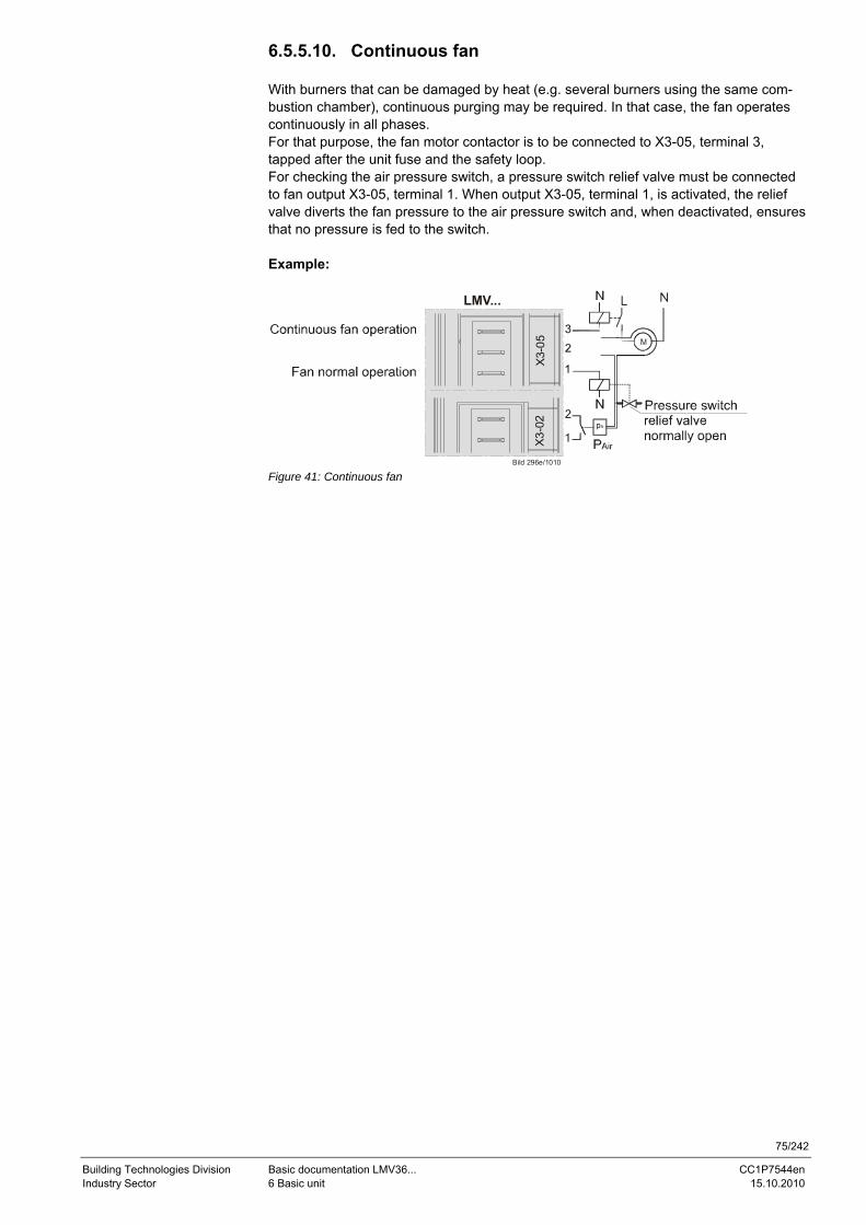
75/242
Building Technologies Division Basic documentation LMV36... CC1P7544en Industry Sector 6 Basic unit 15.10.2010
6.5.5.10. Continuous fan With burners that can be damaged by heat (e.g. several burners using the same com-bustion chamber), continuous purging may be required. In that case, the fan operates continuously in all phases. For that purpose, the fan motor contactor is to be connected to X3-05, terminal 3, tapped after the unit fuse and the safety loop. For checking the air pressure switch, a pressure switch relief valve must be connected to fan output X3-05, terminal 1. When output X3-05, terminal 1, is activated, the relief valve diverts the fan pressure to the air pressure switch and, when deactivated, ensures that no pressure is fed to the switch. Example:
LMV...
Bild 296e/1010
X3-
05X
3-02
Figure 41: Continuous fan
76/242
Building Technologies Division Basic documentation LMV36... CC1P7544en Industry Sector 6 Basic unit 15.10.2010
6.5.5.11. Test function for burner approval – loss-of-flame test (TÜV test)
The purpose of this test is to verify the detection time required in the event of loss of flame when applying for burner approval. When starting the test, the fuel valves are shut to determine the time (resolution of 0.2 seconds) until the basic unit detects loss of flame. Procedure: • Determine the burner output at which the test shall be made, using parameter 133
(fuel 0) or parameter 134 (fuel 1). If these parameters are not set, the test is carried out at the current output of the system
• Start the test by entering the value of 1 for parameter 124. If the burner’s output for the test is set (parameter 133 or 134), the system is driven to that output level first. To ensure this functionality, the presetting of pa-rameter 121 (manual output) is used. This cancels any manual output that was previously active
• Now, the LMV36… shuts the fuel valves, leading to loss of flame • The evaluation is made by the basic unit by measuring the time the system requires
from fuel valve shutdown until loss of flame is detected. Then, the measured value is available as a diagnostic code in connection with error C:7 (loss of flame) The resolution is 0.2 seconds. Example: The display of C:7 D:10 means that the time required from valve shutdown to detection of loss of flame is 2 seconds (D:10 corresponding 10 x 0.2 seconds).
When the test is successfully completed, parameter 124 is reset to 0. If unsuccess-ful, a negative value is delivered for diagnostic purposes and error code 150 is en-tered. -1 = invalid phase (test possible in phase 60 only) – message displayed: C:150 D: 1 -2 = default output < minimum output – message displayed: C:150 D:2 -3 = default output > maximum output – message displayed: C:150 D:3 -4 = manual abortion (no error, start variable was manually reset to 0) – message displayed: C:150 D:4 -5 = timeout with TÜV test (no loss of flame within 50 seconds after valves were shut) – lockout: C:150 D:5 Values previously set for the burner’s output at which the test shall be made (pa-rameter 133 or 134) remain stored.
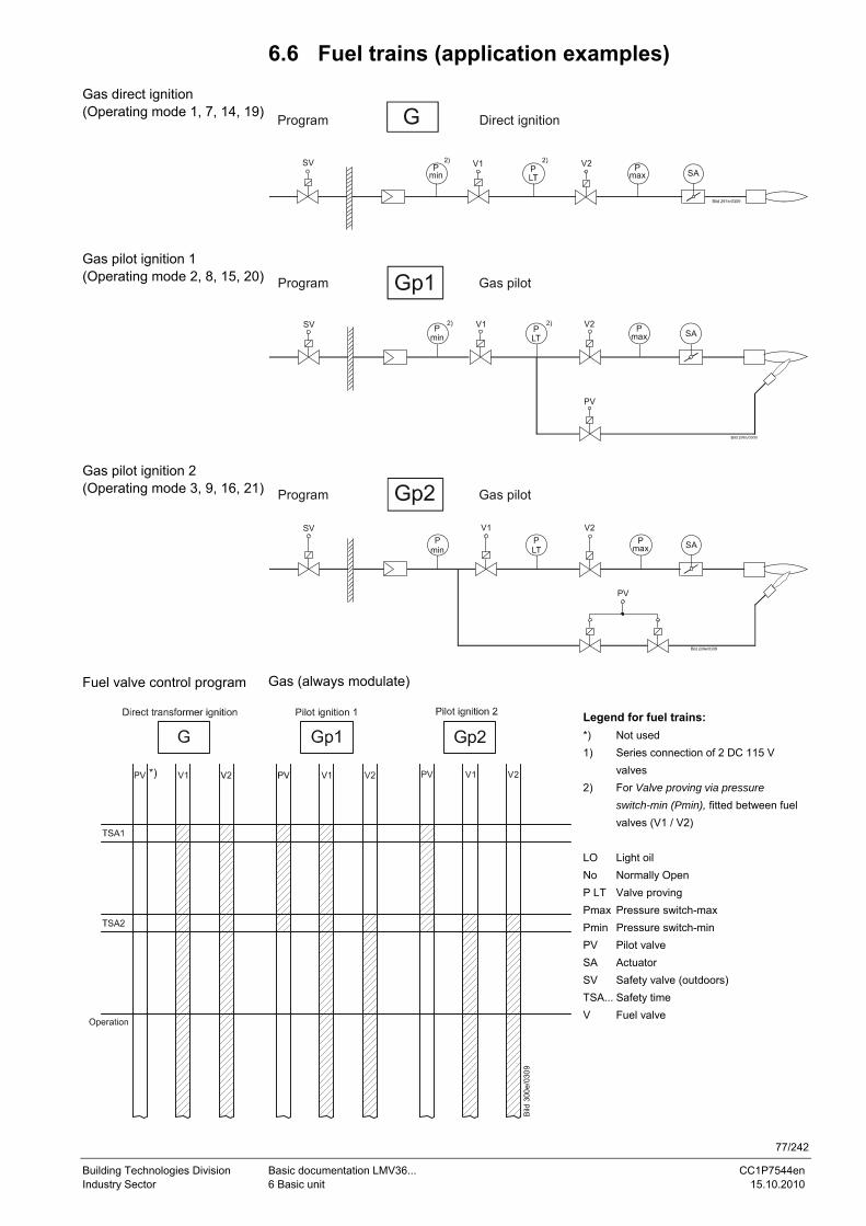
77/242
Building Technologies Division Basic documentation LMV36... CC1P7544en Industry Sector 6 Basic unit 15.10.2010
6.6 Fuel trains (application examples)
SV V1 V2
Direct ignitionGProgram
SAPmin
Pmax
P
SV V1SA
V2
Program Gp1 Gas pilot
PV
Pmin
PLT
Pmax
SV
SA
V2
Program Gp2 Gas pilot
PV
V1P
minPLT
Pmax
Gas (always modulate)
Pilot ignition 1
Gp2
V1 V2
Bild
300
e/03
09
Legend for fuel trains: *) Not used 1) Series connection of 2 DC 115 V valves 2) For Valve proving via pressure switch-min (Pmin), fitted between fuel valves (V1 / V2) LO Light oil No Normally Open P LT Valve proving Pmax Pressure switch-max Pmin Pressure switch-min PV Pilot valve SA Actuator SV Safety valve (outdoors) TSA... Safety time V Fuel valve
Gas direct ignition (Operating mode 1, 7, 14, 19)
Gas pilot ignition 1 (Operating mode 2, 8, 15, 20)
Gas pilot ignition 2 (Operating mode 3, 9, 16, 21)
Fuel valve control program
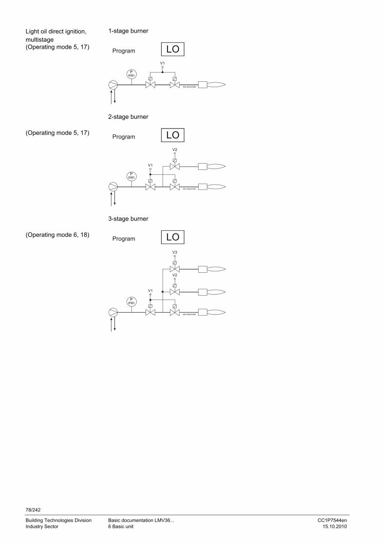
78/242
Building Technologies Division Basic documentation LMV36... CC1P7544en Industry Sector 6 Basic unit 15.10.2010
1-stage burner
LOProgram
Pmin
V1
2-stage burner
LOProgram
Pmin
V1
V2
3-stage burner
LOProgram
Pmin
V1
V2
V3
Light oil direct ignition, multistage (Operating mode 5, 17)
(Operating mode 5, 17)
(Operating mode 6, 18)
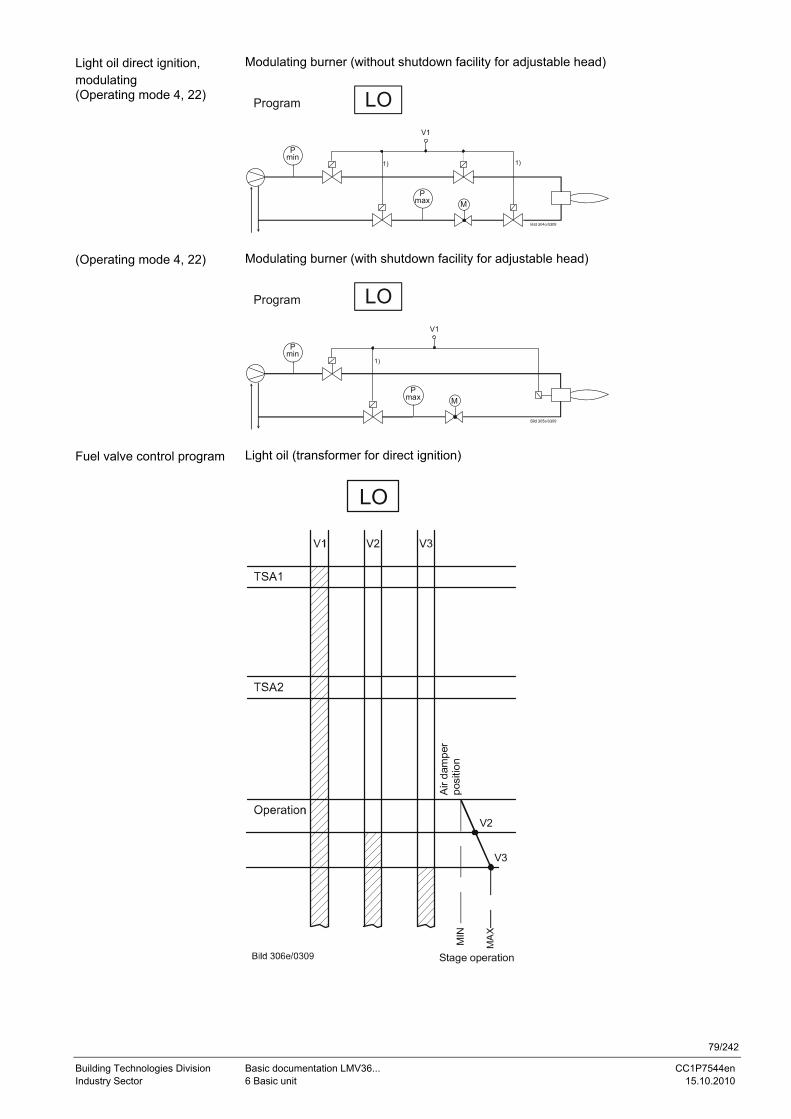
79/242
Building Technologies Division Basic documentation LMV36... CC1P7544en Industry Sector 6 Basic unit 15.10.2010
Modulating burner (without shutdown facility for adjustable head)
LOProgram
V1
Pmax M
Pmin
1) 1)
Modulating burner (with shutdown facility for adjustable head)
LOProgram
V1
Pmax M
Pmin
1)
Light oil (transformer for direct ignition)
LO
V3
V2
MIN
Air
dam
per
posi
tion
Stage operation
Light oil direct ignition, modulating (Operating mode 4, 22)
(Operating mode 4, 22)
Fuel valve control program
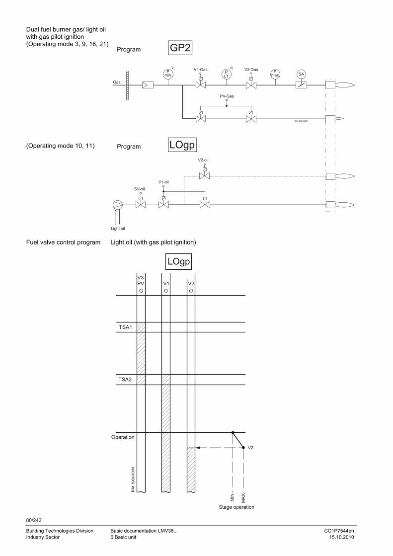
80/242
Building Technologies Division Basic documentation LMV36... CC1P7544en Industry Sector 6 Basic unit 15.10.2010
V1-Gas V2-Gas
GP2Program
SAPmin
Pmax
P
Gas
PV-Gas
SV-oil
LOgpProgram
V1-oil
V2-oil
Light oil Light oil (with gas pilot ignition)
V2
Stage operation
MIN
MA
X
V3PV V1 V2
TSA2
TSA1
Dual fuel burner gas/ light oil with gas pilot ignition (Operating mode 3, 9, 16, 21) (Operating mode 10, 11)
Fuel valve control program
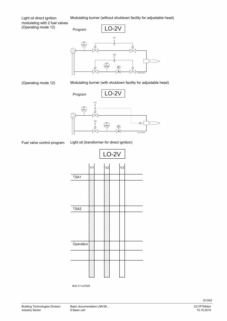
81/242
Building Technologies Division Basic documentation LMV36... CC1P7544en Industry Sector 6 Basic unit 15.10.2010
Modulating burner (without shutdown facility for adjustable head)
LO-2VProgram
Pmax M
Pmin 1)
V1
1)
V2
Modulating burner (with shutdown facility for adjustable head)
LO-2VProgram
V1
Pmax M
Pmin
V2
Light oil (transformer for direct ignition)
LO-2V
Light oil direct ignition modulating with 2 fuel valves(Operating mode 12)
(Operating mode 12)
Fuel valve control program
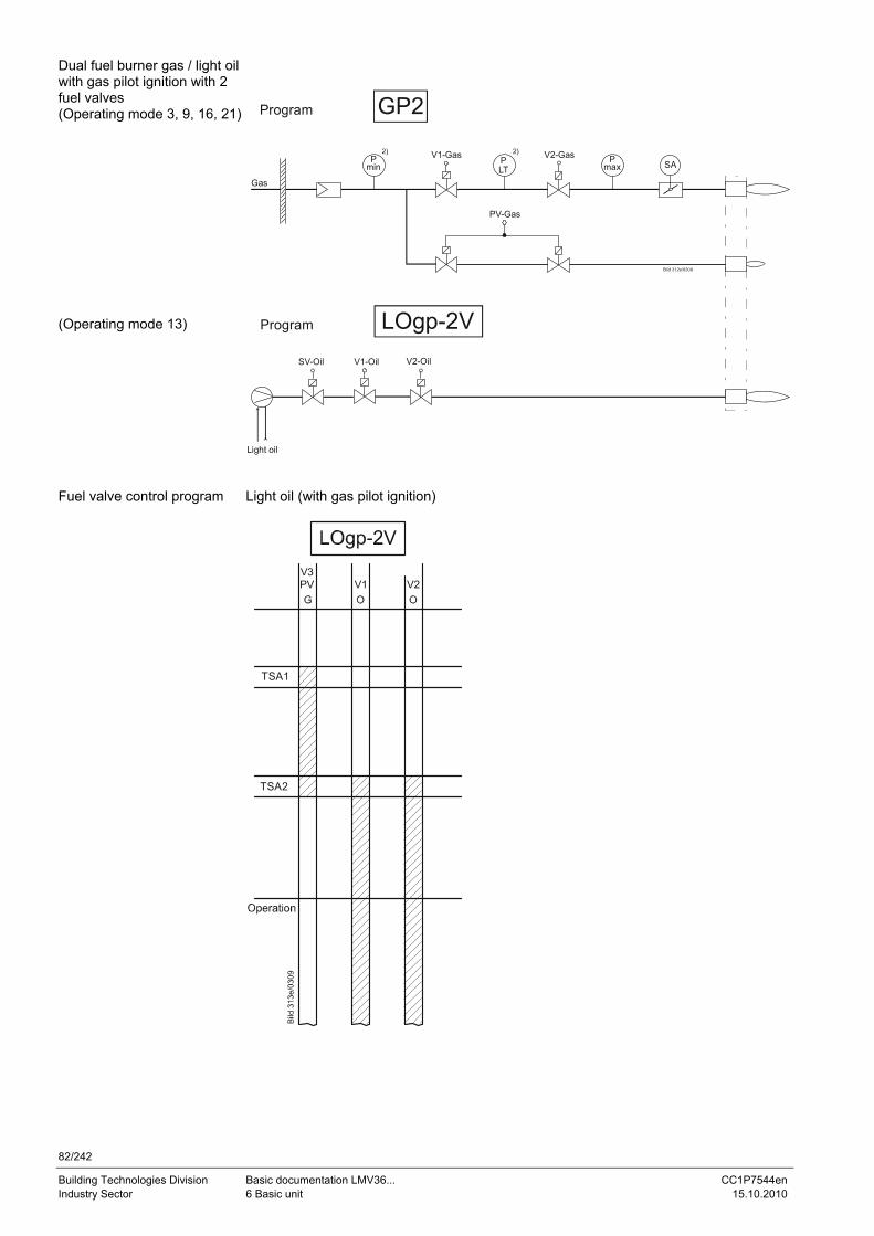
82/242
Building Technologies Division Basic documentation LMV36... CC1P7544en Industry Sector 6 Basic unit 15.10.2010
V1-Gas V2-Gas
GP2Program
SAPmin
Pmax
P
Gas
PV-Gas
SV-Oil
LOgp-2VProgram
V1-Oil V2-Oil
Light oil Light oil (with gas pilot ignition)
V3PV V1 V2
TSA2
TSA1
Dual fuel burner gas / light oil with gas pilot ignition with 2 fuel valves (Operating mode 3, 9, 16, 21) (Operating mode 13)
Fuel valve control program
83/242
Building Technologies Division Basic documentation LMV36... CC1P7544en Industry Sector 6 Basic unit 15.10.2010
6.7 Sequence diagrams The phase numbers given in the sequence diagrams can be read from the following process data:
No. Parameter
961 Phase (state for external module and display)
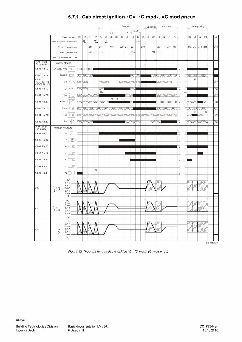
84/242
Building Technologies Division Basic documentation LMV36... CC1P7544en Industry Sector 6 Basic unit 15.10.2010
6.7.1 Gas direct ignition «G», «G mod», «G mod pneu»
M
Fuel
Air
0°
0°
t1
p
P
P
R (ON)
LP
Z
AL
V1
V2
0°
5 s5 s 30 s
POC *)
Function / Inputs
Function / OutputsRAST plugPin number
RAST plugPin number
X3-04 Pin 1/2
X5-03 Pin 1/4
X10-05 Pin 2 / Pin 3/4X10-06 Pin 1/2
X3-02 Pin 1/2
X5-01 Pin 2/3
X5-02 Pin 2/3
X5-02 Pin 2/3
X3-05 Pin 1
X4-02 Pin 2/3
X6-03 Pin 2/3
X8-02 Pin 1/3
X7-01 Pin 2/3
X7-02 Pin 2/3
X3-05 Pin 2
X54
X53
X74
P
PX9-04 Pin 2/3
X5-01 Pin 2/3
Figure 42: Program for gas direct ignition (G), (G mod), (G mod pneu)
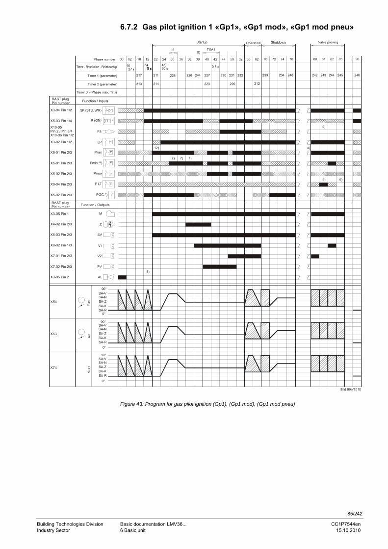
85/242
Building Technologies Division Basic documentation LMV36... CC1P7544en Industry Sector 6 Basic unit 15.10.2010
6.7.2 Gas pilot ignition 1 «Gp1», «Gp1 mod», «Gp1 mod pneu»
M
Fuel
Air
0°
0°
t1
p
P
P
R (ON)
LP
Z
AL
V1
V2
0°
5 s5 s 30 s
POC *)
Function / Inputs
Function / OutputsRAST plugPin number
RAST plugPin number
X3-04 Pin 1/2
X5-03 Pin 1/4
X10-05 Pin 2 / Pin 3/4X10-06 Pin 1/2
X3-02 Pin 1/2
X5-01 Pin 2/3
X5-02 Pin 2/3
X5-02 Pin 2/3
X3-05 Pin 1
X4-02 Pin 2/3
X6-03 Pin 2/3
X8-02 Pin 1/3
X7-01 Pin 2/3
X7-02 Pin 2/3
X3-05 Pin 2
X54
X53
X74
P
PX9-04 Pin 2/3
X5-01 Pin 2/3
Figure 43: Program for gas pilot ignition (Gp1), (Gp1 mod), (Gp1 mod pneu)
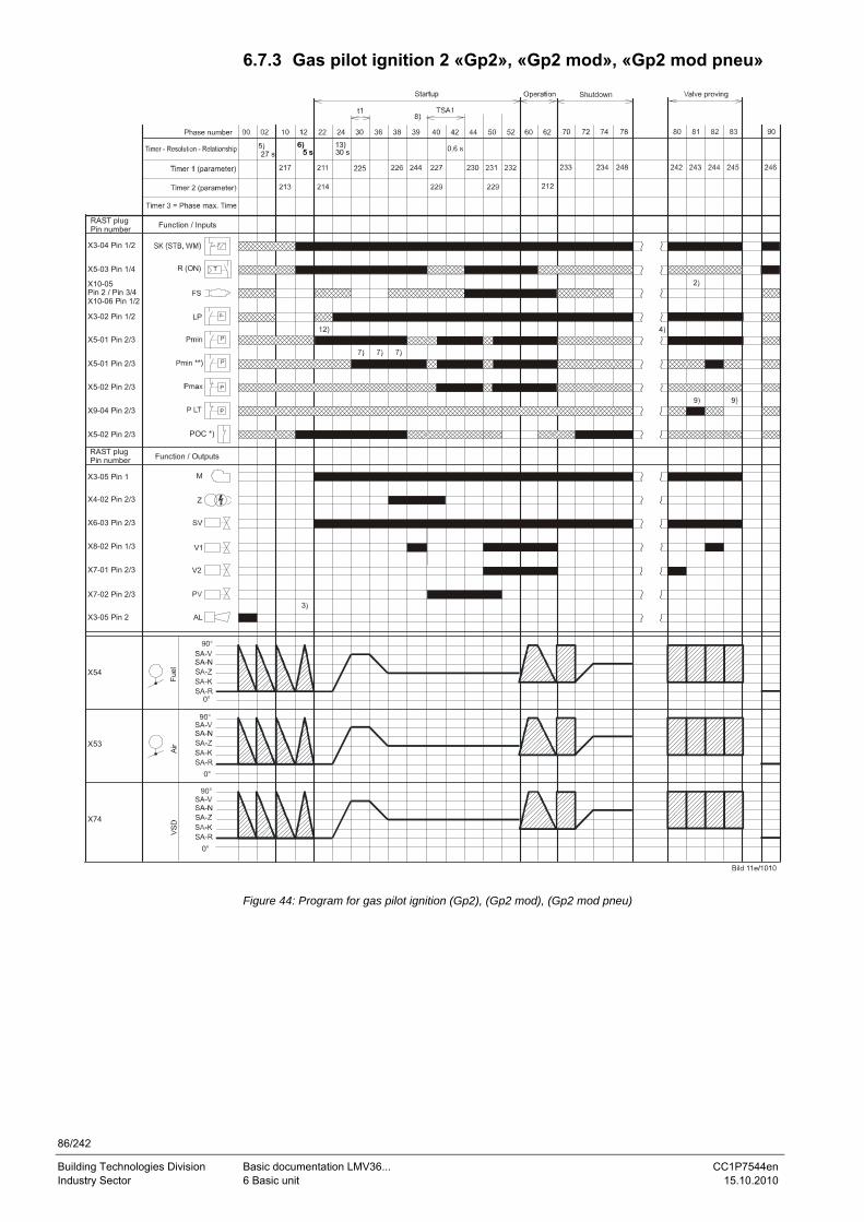
86/242
Building Technologies Division Basic documentation LMV36... CC1P7544en Industry Sector 6 Basic unit 15.10.2010
6.7.3 Gas pilot ignition 2 «Gp2», «Gp2 mod», «Gp2 mod pneu»
M
Fuel
Air
0°
0°
t1
p
P
P
R (ON)
LP
Z
AL
V1
V2
0°
5 s5 s 30 s
POC *)
Function / Inputs
Function / OutputsRAST plugPin number
RAST plugPin number
X3-04 Pin 1/2
X5-03 Pin 1/4
X10-05 Pin 2 / Pin 3/4X10-06 Pin 1/2
X3-02 Pin 1/2
X5-01 Pin 2/3
X5-02 Pin 2/3
X5-02 Pin 2/3
X3-05 Pin 1
X4-02 Pin 2/3
X6-03 Pin 2/3
X8-02 Pin 1/3
X7-01 Pin 2/3
X7-02 Pin 2/3
X3-05 Pin 2
X54
X53
X74
P
PX9-04 Pin 2/3
X5-01 Pin 2/3
Figure 44: Program for gas pilot ignition (Gp2), (Gp2 mod), (Gp2 mod pneu)
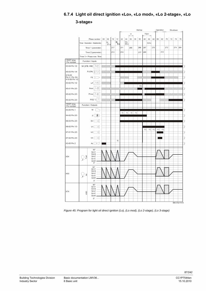
87/242
Building Technologies Division Basic documentation LMV36... CC1P7544en Industry Sector 6 Basic unit 15.10.2010
6.7.4 Light oil direct ignition «Lo», «Lo mod», «Lo 2-stage», «Lo
3-stage»
M
Fuel
Air
0°
0°
t1
p
P
P
R (ON)
LP
Z
AL
V1
V2
0°
5 s5 s 30 s
POC *)
Function / Inputs
Function / OutputsRAST plugPin number
RAST plugPin number
X3-04 Pin 1/2
X5-03 Pin 1/4
X10-05 Pin 2 / Pin 3/4X10-06 Pin 1/2
X3-02 Pin 1/2
X5-01 Pin 2/3
X5-02 Pin 2/3
X5-02 Pin 2/3
X3-05 Pin 1
X4-02 Pin 2/3
X6-03 Pin 2/3
X8-02 Pin 1/3
X7-01 Pin 2/3
X7-02 Pin 2/3
X3-05 Pin 2
X54
X53
X74
Figure 45: Program for light oil direct ignition (Lo), (Lo mod), (Lo 2-stage), (Lo 3-stage)
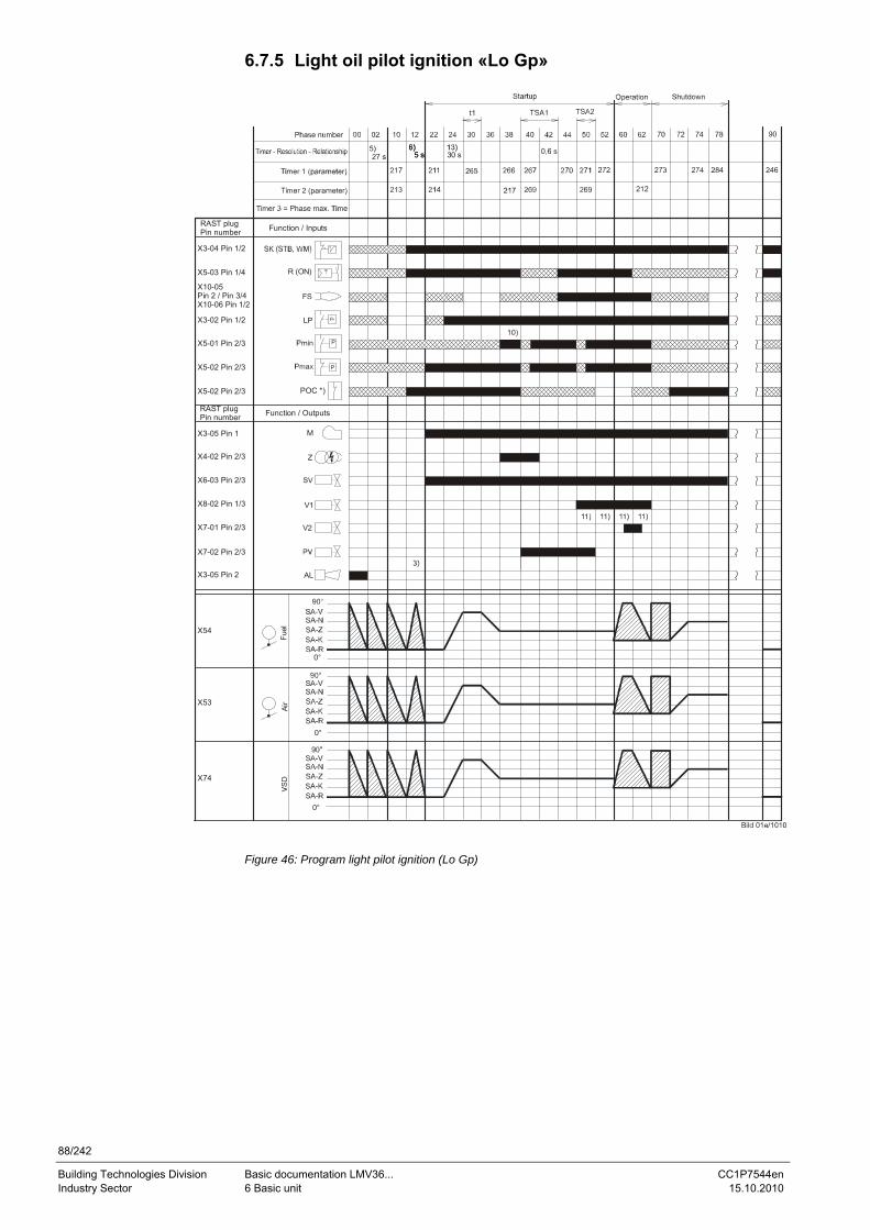
88/242
Building Technologies Division Basic documentation LMV36... CC1P7544en Industry Sector 6 Basic unit 15.10.2010
6.7.5 Light oil pilot ignition «Lo Gp»
M
Fuel
Air
0°
0°
t1
p
P
P
R (ON)
LP
Z
AL
V1
V2
0°
5 s5 s 30 s
POC *)
Function / Inputs
Function / OutputsRAST plugPin number
RAST plugPin number
X3-04 Pin 1/2
X5-03 Pin 1/4
X10-05 Pin 2 / Pin 3/4X10-06 Pin 1/2
X3-02 Pin 1/2
X5-01 Pin 2/3
X5-02 Pin 2/3
X5-02 Pin 2/3
X3-05 Pin 1
X4-02 Pin 2/3
X6-03 Pin 2/3
X8-02 Pin 1/3
X7-01 Pin 2/3
X7-02 Pin 2/3
X3-05 Pin 2
X54
X53
X74
Figure 46: Program light pilot ignition (Lo Gp)
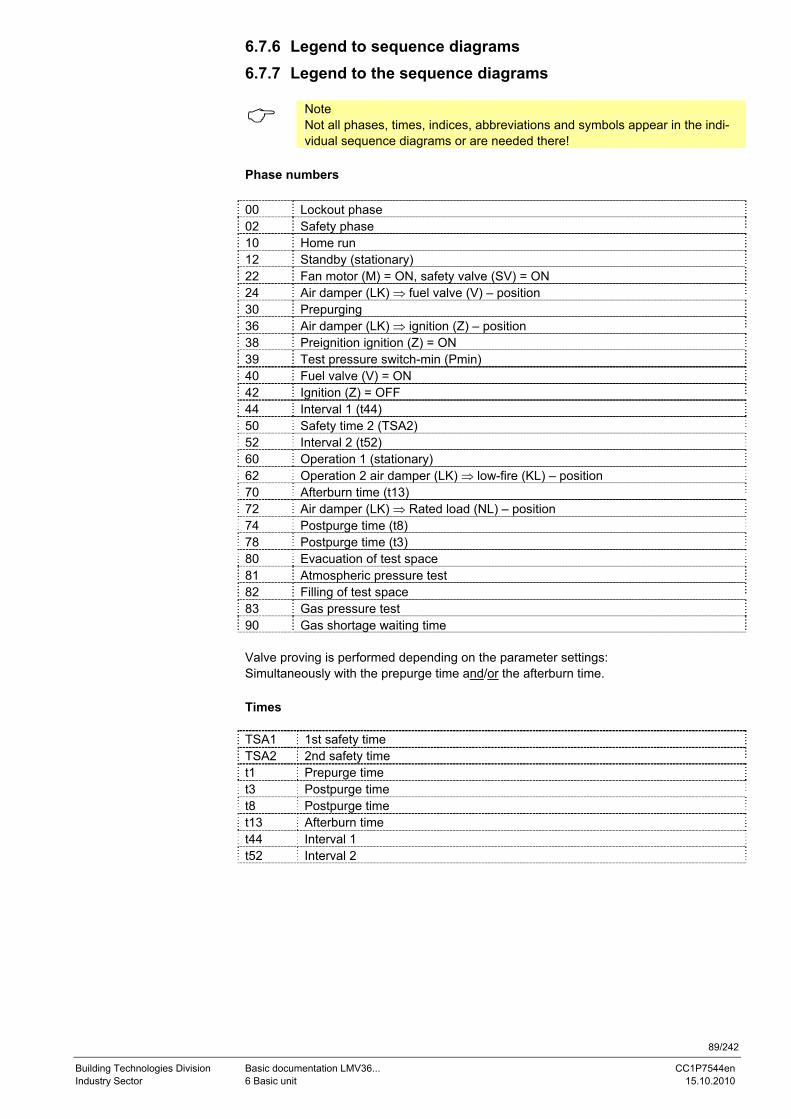
89/242
Building Technologies Division Basic documentation LMV36... CC1P7544en Industry Sector 6 Basic unit 15.10.2010
6.7.6 Legend to sequence diagrams 6.7.7 Legend to the sequence diagrams
Note Not all phases, times, indices, abbreviations and symbols appear in the indi-vidual sequence diagrams or are needed there!
Phase numbers 00 Lockout phase 02 Safety phase 10 Home run 12 Standby (stationary) 22 Fan motor (M) = ON, safety valve (SV) = ON 24 Air damper (LK) ⇒ fuel valve (V) – position 30 Prepurging 36 Air damper (LK) ⇒ ignition (Z) – position 38 Preignition ignition (Z) = ON 39 Test pressure switch-min (Pmin) 40 Fuel valve (V) = ON 42 Ignition (Z) = OFF 44 Interval 1 (t44) 50 Safety time 2 (TSA2) 52 Interval 2 (t52) 60 Operation 1 (stationary) 62 Operation 2 air damper (LK) ⇒ low-fire (KL) – position 70 Afterburn time (t13) 72 Air damper (LK) ⇒ Rated load (NL) – position 74 Postpurge time (t8) 78 Postpurge time (t3) 80 Evacuation of test space 81 Atmospheric pressure test 82 Filling of test space 83 Gas pressure test 90 Gas shortage waiting time Valve proving is performed depending on the parameter settings: Simultaneously with the prepurge time and/or the afterburn time. Times TSA1 1st safety time TSA2 2nd safety time t1 Prepurge time t3 Postpurge time t8 Postpurge time t13 Afterburn time t44 Interval 1 t52 Interval 2
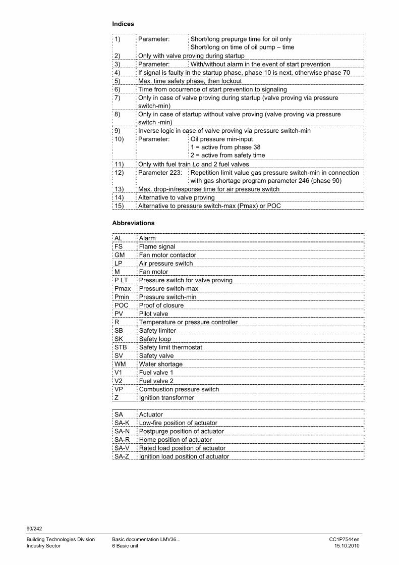
90/242
Building Technologies Division Basic documentation LMV36... CC1P7544en Industry Sector 6 Basic unit 15.10.2010
Indices 1) Parameter: Short/long prepurge time for oil only
Short/long on time of oil pump – time 2) Only with valve proving during startup 3) Parameter: With/without alarm in the event of start prevention 4) If signal is faulty in the startup phase, phase 10 is next, otherwise phase 70 5) Max. time safety phase, then lockout 6) Time from occurrence of start prevention to signaling 7) Only in case of valve proving during startup (valve proving via pressure
switch-min) 8) Only in case of startup without valve proving (valve proving via pressure
switch -min) 9) Inverse logic in case of valve proving via pressure switch-min 10) Parameter: Oil pressure min-input
1 = active from phase 38 2 = active from safety time
11) Only with fuel train Lo and 2 fuel valves 12) Parameter 223: Repetition limit value gas pressure switch-min in connection
with gas shortage program parameter 246 (phase 90) 13) Max. drop-in/response time for air pressure switch 14) Alternative to valve proving 15) Alternative to pressure switch-max (Pmax) or POC
Abbreviations AL Alarm FS Flame signal GM Fan motor contactor LP Air pressure switch M Fan motor P LT Pressure switch for valve proving Pmax Pressure switch-max Pmin Pressure switch-min POC Proof of closure PV Pilot valve R Temperature or pressure controller SB Safety limiter SK Safety loop STB Safety limit thermostat SV Safety valve WM Water shortage V1 Fuel valve 1 V2 Fuel valve 2 VP Combustion pressure switch Z Ignition transformer SA Actuator SA-K Low-fire position of actuator SA-N Postpurge position of actuator SA-R Home position of actuator SA-V Rated load position of actuator SA-Z Ignition load position of actuator
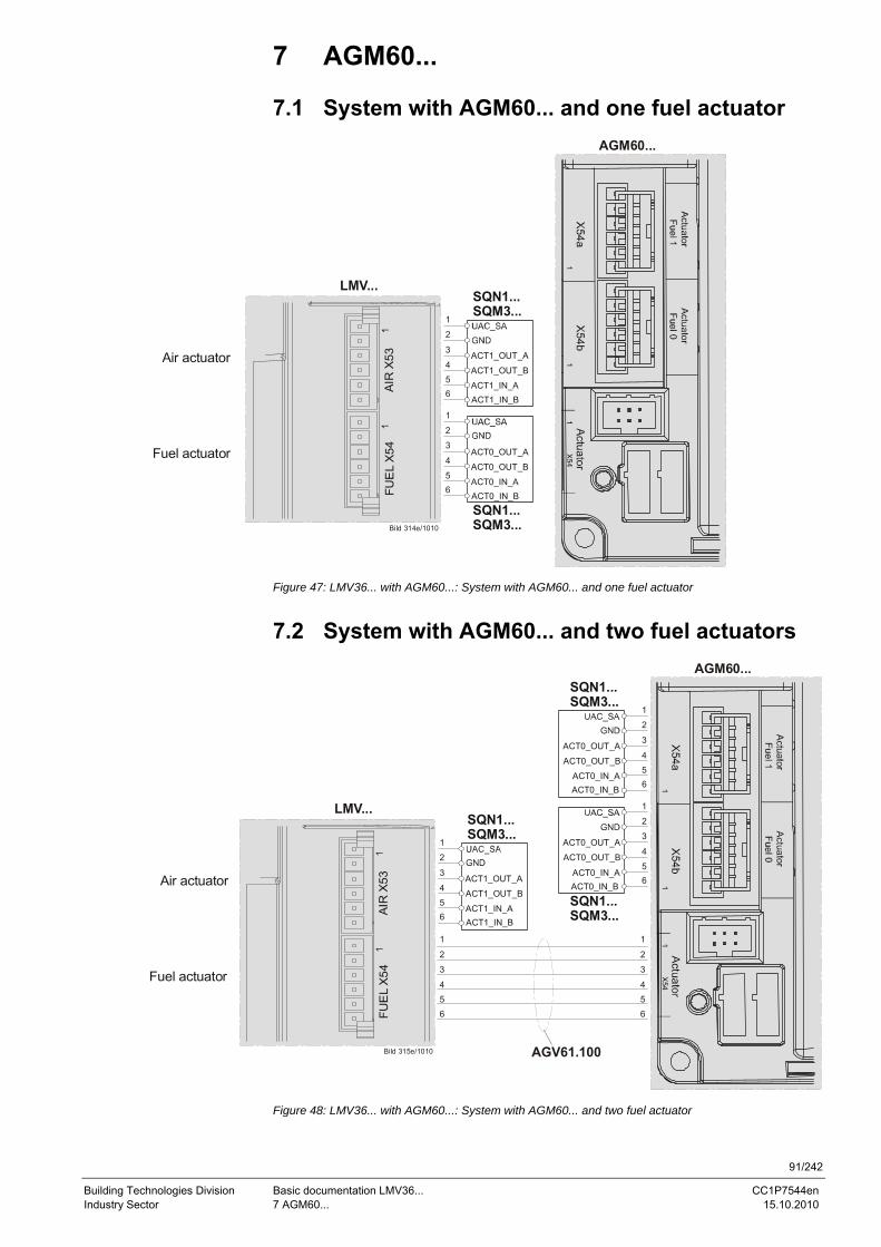
91/242
Building Technologies Division Basic documentation LMV36... CC1P7544en Industry Sector 7 AGM60... 15.10.2010
7 AGM60...
7.1 System with AGM60... and one fuel actuator
LMV...
Bild 314e/1010
Fuel actuator
AGM60...
AIR
X53
FUE
L X
54
Air actuator ACT1_OUT_A
ACT1_OUT_B
ACT1_IN_AACT1_IN_B
SQN1...SQM3...
1
2
3
456
ACT0_OUT_A
ACT0_OUT_B
ACT0_IN_AACT0_IN_B
SQN1...SQM3...
1
2
3
4
56
Figure 47: LMV36... with AGM60...: System with AGM60... and one fuel actuator
7.2 System with AGM60... and two fuel actuators
LMV...
Bild 315e/1010
Fuel actuator
AGM60...
AIR
X53
FUE
L X
54
Air actuator
1
2
3
456
1
2
3
456
ACT1_OUT_A
ACT1_OUT_B
ACT1_IN_AACT1_IN_B
SQN1...SQM3...
1
2
3
456
AGV61.100
ACT0_OUT_A
ACT0_OUT_B
ACT0_IN_AACT0_IN_B
SQN1...SQM3...
1
2
3
456
ACT0_OUT_A
ACT0_OUT_B
ACT0_IN_AACT0_IN_B
SQN1...SQM3...
1
2
3
4
56
Figure 48: LMV36... with AGM60...: System with AGM60... and two fuel actuator
92/242
Building Technologies Division Basic documentation LMV36... CC1P7544en Industry Sector 7 AGM60... 15.10.2010
7.3 Connecting cable between AGM60... and LMV36... basic unit (AGV61.100 cable)
This cable is required when, due to the selected type of fuel train (refer to chapter Selec-tion of operating mode), 2 fuel actuators are needed. For that, the 2 fuel actuators must be connected to terminals X54a and X54b of the AGM60... The AGV61.100 cable is required for making the electrical connection be-tween the 2 fuel actuators and the basic unit. If only 1 fuel actuator is used, it must be connected directly to the basic unit. Connection plug assignment of cable: 1 = pink or alternatively red 2 = white or alternatively black 3 = brown 4 = grey 5 = yellow 6 = green
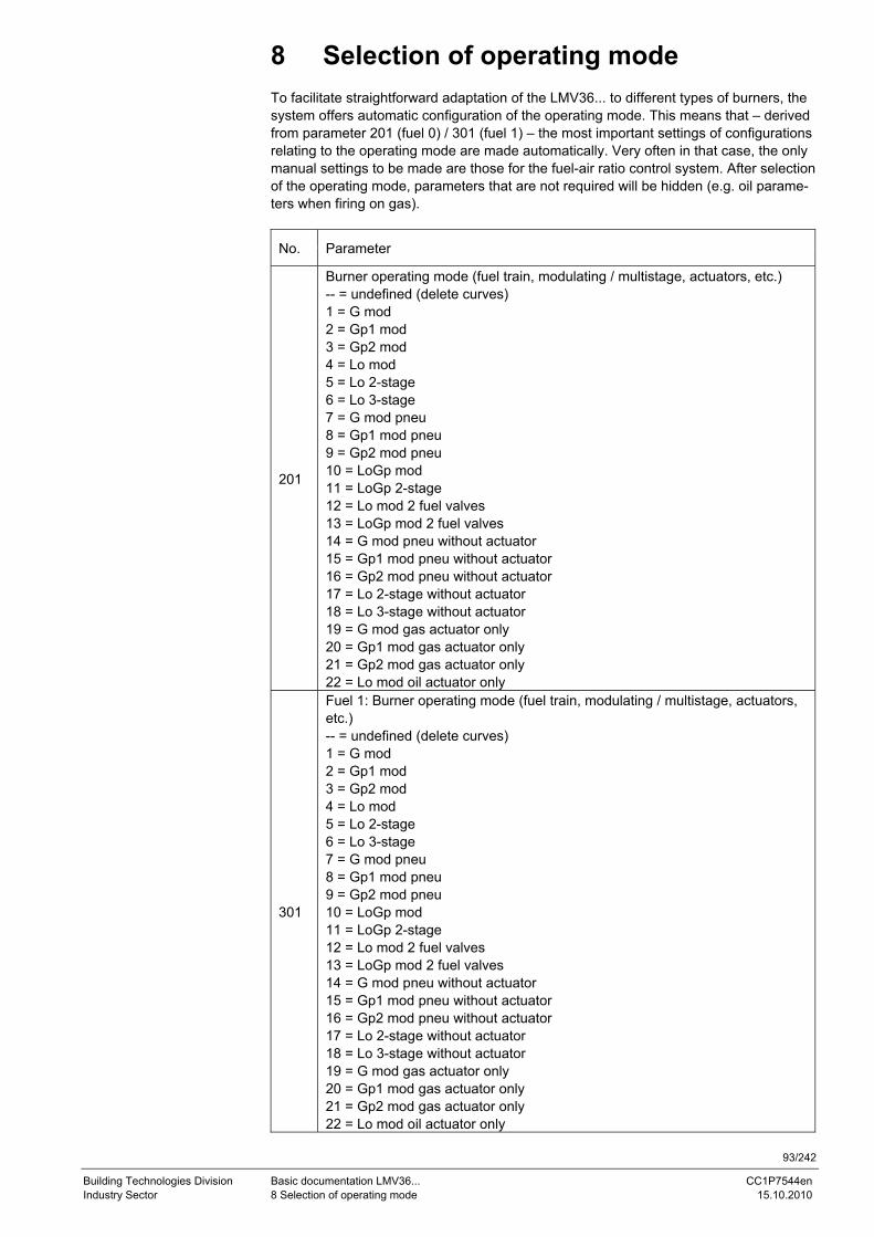
93/242
Building Technologies Division Basic documentation LMV36... CC1P7544en Industry Sector 8 Selection of operating mode 15.10.2010
8 Selection of operating mode To facilitate straightforward adaptation of the LMV36... to different types of burners, the system offers automatic configuration of the operating mode. This means that – derived from parameter 201 (fuel 0) / 301 (fuel 1) – the most important settings of configurations relating to the operating mode are made automatically. Very often in that case, the only manual settings to be made are those for the fuel-air ratio control system. After selection of the operating mode, parameters that are not required will be hidden (e.g. oil parame-ters when firing on gas).
No. Parameter
201
Burner operating mode (fuel train, modulating / multistage, actuators, etc.) -- = undefined (delete curves) 1 = G mod 2 = Gp1 mod 3 = Gp2 mod 4 = Lo mod 5 = Lo 2-stage 6 = Lo 3-stage 7 = G mod pneu 8 = Gp1 mod pneu 9 = Gp2 mod pneu 10 = LoGp mod 11 = LoGp 2-stage 12 = Lo mod 2 fuel valves 13 = LoGp mod 2 fuel valves 14 = G mod pneu without actuator 15 = Gp1 mod pneu without actuator 16 = Gp2 mod pneu without actuator 17 = Lo 2-stage without actuator 18 = Lo 3-stage without actuator 19 = G mod gas actuator only 20 = Gp1 mod gas actuator only 21 = Gp2 mod gas actuator only 22 = Lo mod oil actuator only
301
Fuel 1: Burner operating mode (fuel train, modulating / multistage, actuators, etc.) -- = undefined (delete curves) 1 = G mod 2 = Gp1 mod 3 = Gp2 mod 4 = Lo mod 5 = Lo 2-stage 6 = Lo 3-stage 7 = G mod pneu 8 = Gp1 mod pneu 9 = Gp2 mod pneu 10 = LoGp mod 11 = LoGp 2-stage 12 = Lo mod 2 fuel valves 13 = LoGp mod 2 fuel valves 14 = G mod pneu without actuator 15 = Gp1 mod pneu without actuator 16 = Gp2 mod pneu without actuator 17 = Lo 2-stage without actuator 18 = Lo 3-stage without actuator 19 = G mod gas actuator only 20 = Gp1 mod gas actuator only 21 = Gp2 mod gas actuator only 22 = Lo mod oil actuator only
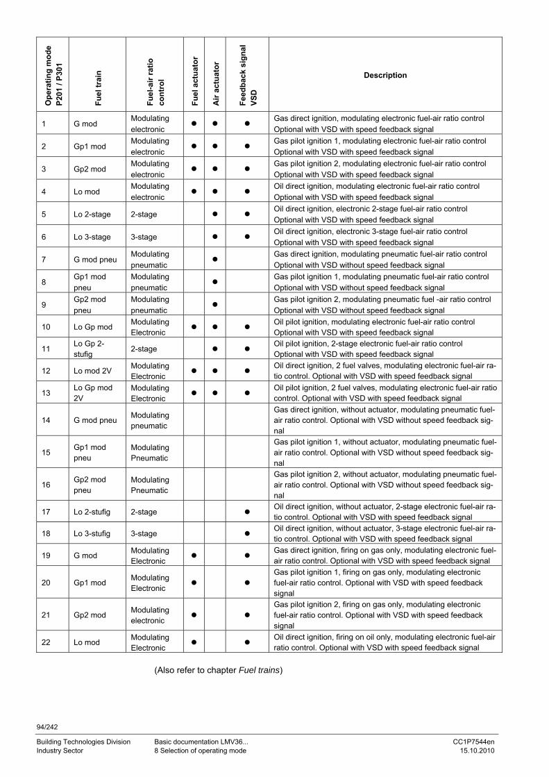
94/242
Building Technologies Division Basic documentation LMV36... CC1P7544en Industry Sector 8 Selection of operating mode 15.10.2010
Ope
ratin
g m
ode
P201
/ P3
01
Fuel
trai
n
Fuel
-air
ratio
co
ntro
l
Fuel
act
uato
r
Air
actu
ator
Feed
back
sig
nal
VSD
Description
1 G mod Modulating electronic
● ● ● Gas direct ignition, modulating electronic fuel-air ratio control Optional with VSD with speed feedback signal
2 Gp1 mod Modulating electronic
● ● ● Gas pilot ignition 1, modulating electronic fuel-air ratio control Optional with VSD with speed feedback signal
3 Gp2 mod Modulating electronic
● ● ● Gas pilot ignition 2, modulating electronic fuel-air ratio control Optional with VSD with speed feedback signal
4 Lo mod Modulating electronic
● ● ● Oil direct ignition, modulating electronic fuel-air ratio control Optional with VSD with speed feedback signal
5 Lo 2-stage 2-stage ● ● Oil direct ignition, electronic 2-stage fuel-air ratio control Optional with VSD with speed feedback signal
6 Lo 3-stage 3-stage ● ● Oil direct ignition, electronic 3-stage fuel-air ratio control Optional with VSD with speed feedback signal
7 G mod pneu Modulating pneumatic
● Gas direct ignition, modulating pneumatic fuel-air ratio control Optional with VSD without speed feedback signal
8 Gp1 mod pneu
Modulating pneumatic
● Gas pilot ignition 1, modulating pneumatic fuel-air ratio control Optional with VSD without speed feedback signal
9 Gp2 mod pneu
Modulating pneumatic
● Gas pilot ignition 2, modulating pneumatic fuel -air ratio control Optional with VSD without speed feedback signal
10 Lo Gp mod Modulating Electronic ● ● ●
Oil pilot ignition, modulating electronic fuel-air ratio control Optional with VSD with speed feedback signal
11 Lo Gp 2-stufig
2-stage ● ● Oil pilot ignition, 2-stage electronic fuel-air ratio control Optional with VSD with speed feedback signal
12 Lo mod 2V Modulating Electronic ● ● ●
Oil direct ignition, 2 fuel valves, modulating electronic fuel-air ra-tio control. Optional with VSD with speed feedback signal
13 Lo Gp mod 2V
Modulating Electronic ● ● ●
Oil pilot ignition, 2 fuel valves, modulating electronic fuel-air ratio control. Optional with VSD with speed feedback signal
14 G mod pneu Modulating pneumatic
Gas direct ignition, without actuator, modulating pneumatic fuel-air ratio control. Optional with VSD without speed feedback sig-nal
15 Gp1 mod pneu
Modulating Pneumatic
Gas pilot ignition 1, without actuator, modulating pneumatic fuel-air ratio control. Optional with VSD without speed feedback sig-nal
16 Gp2 mod pneu
Modulating Pneumatic
Gas pilot ignition 2, without actuator, modulating pneumatic fuel-air ratio control. Optional with VSD without speed feedback sig-nal
17 Lo 2-stufig 2-stage ● Oil direct ignition, without actuator, 2-stage electronic fuel-air ra-tio control. Optional with VSD with speed feedback signal
18 Lo 3-stufig 3-stage ● Oil direct ignition, without actuator, 3-stage electronic fuel-air ra-tio control. Optional with VSD with speed feedback signal
19 G mod Modulating Electronic ● ●
Gas direct ignition, firing on gas only, modulating electronic fuel-air ratio control. Optional with VSD with speed feedback signal
20 Gp1 mod Modulating Electronic ● ●
Gas pilot ignition 1, firing on gas only, modulating electronic fuel-air ratio control. Optional with VSD with speed feedback signal
21 Gp2 mod Modulating electronic ● ●
Gas pilot ignition 2, firing on gas only, modulating electronic fuel-air ratio control. Optional with VSD with speed feedback signal
22 Lo mod Modulating Electronic ● ●
Oil direct ignition, firing on oil only, modulating electronic fuel-air ratio control. Optional with VSD with speed feedback signal
(Also refer to chapter Fuel trains)
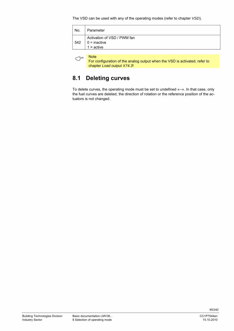
95/242
Building Technologies Division Basic documentation LMV36... CC1P7544en Industry Sector 8 Selection of operating mode 15.10.2010
The VSD can be used with any of the operating modes (refer to chapter VSD).
No. Parameter
542 Activation of VSD / PWM fan 0 = inactive 1 = active
Note For configuration of the analog output when the VSD is activated, refer to chapter Load output X74.3!
8.1 Deleting curves To delete curves, the operating mode must be set to undefined «--». In that case, only the fuel curves are deleted, the direction of rotation or the reference position of the ac-tuators is not changed.
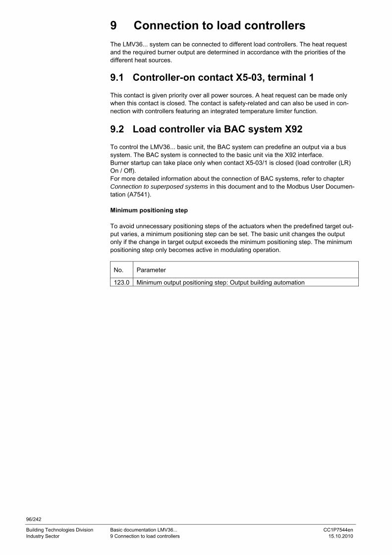
96/242
Building Technologies Division Basic documentation LMV36... CC1P7544en Industry Sector 9 Connection to load controllers 15.10.2010
9 Connection to load controllers The LMV36... system can be connected to different load controllers. The heat request and the required burner output are determined in accordance with the priorities of the different heat sources.
9.1 Controller-on contact X5-03, terminal 1 This contact is given priority over all power sources. A heat request can be made only when this contact is closed. The contact is safety-related and can also be used in con-nection with controllers featuring an integrated temperature limiter function.
9.2 Load controller via BAC system X92 To control the LMV36... basic unit, the BAC system can predefine an output via a bus system. The BAC system is connected to the basic unit via the X92 interface. Burner startup can take place only when contact X5-03/1 is closed (load controller (LR) On / Off). For more detailed information about the connection of BAC systems, refer to chapter Connection to superposed systems in this document and to the Modbus User Documen-tation (A7541). Minimum positioning step To avoid unnecessary positioning steps of the actuators when the predefined target out-put varies, a minimum positioning step can be set. The basic unit changes the output only if the change in target output exceeds the minimum positioning step. The minimum positioning step only becomes active in modulating operation.
No. Parameter
123.0 Minimum output positioning step: Output building automation
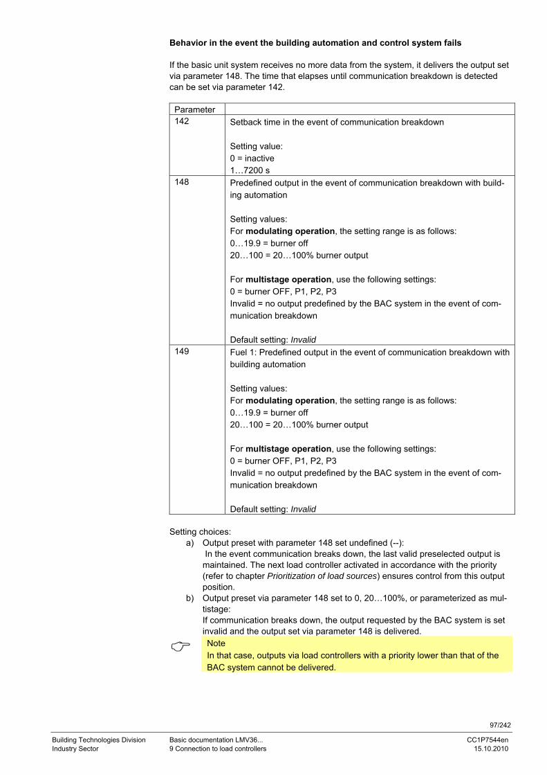
97/242
Building Technologies Division Basic documentation LMV36... CC1P7544en Industry Sector 9 Connection to load controllers 15.10.2010
Behavior in the event the building automation and control system fails If the basic unit system receives no more data from the system, it delivers the output set via parameter 148. The time that elapses until communication breakdown is detected can be set via parameter 142.
Parameter 142 Setback time in the event of communication breakdown
Setting value: 0 = inactive 1…7200 s
148 Predefined output in the event of communication breakdown with build-ing automation Setting values: For modulating operation, the setting range is as follows: 0…19.9 = burner off 20…100 = 20…100% burner output For multistage operation, use the following settings: 0 = burner OFF, P1, P2, P3 Invalid = no output predefined by the BAC system in the event of com-munication breakdown Default setting: Invalid
149 Fuel 1: Predefined output in the event of communication breakdown with building automation Setting values: For modulating operation, the setting range is as follows: 0…19.9 = burner off 20…100 = 20…100% burner output For multistage operation, use the following settings: 0 = burner OFF, P1, P2, P3 Invalid = no output predefined by the BAC system in the event of com-munication breakdown Default setting: Invalid
Setting choices:
a) Output preset with parameter 148 set undefined (--): In the event communication breaks down, the last valid preselected output is maintained. The next load controller activated in accordance with the priority (refer to chapter Prioritization of load sources) ensures control from this output position.
b) Output preset via parameter 148 set to 0, 20…100%, or parameterized as mul-tistage: If communication breaks down, the output requested by the BAC system is set invalid and the output set via parameter 148 is delivered.
Note In that case, outputs via load controllers with a priority lower than that of the BAC system cannot be delivered.
98/242
Building Technologies Division Basic documentation LMV36... CC1P7544en Industry Sector 9 Connection to load controllers 15.10.2010
9.3 Manual output A manual output can be set with the Normal display of the display and operating unit or via the PC tool. Manual output via the display and operating unit Manual output can be activated or adjusted by keeping the F button depressed for at le-ast 1 second and by pressing the + or – button. Output 0 means Manually off. As long as manual output is active, the output appearing on the normal display blinks. To deactivate and to change to automatic operation, press Esc for 3 seconds. If Manually off is activated, it is stored via mains OFF. On power return, the burner assumes the Manually off position (OFF blinking) (refer to chapter Operation). Fuel changeover resets the manual output to Invalid. Exception: Setting Manually off is maintained after fuel changeover also. Activation of Manually off in operation To activate Manually off, first run the system to the minimum output limit. Then, keep the F button depressed for at least 1 second and press the – button. Manually off is activated by releasing the F button and by pressing again the – button.
Caution! Manually off must not be used by itself to put a burner out of operation when doing mounting work, or when the burner is not ready for operation. The safety notes in chapter Safety notes must be observed!
Manual output via the PC tool Refer to description of the PC tool (J7352).
9.4 Output with curve settings To set the curves via the display and operating unit or the PC tool, a special parameteri-zation output is provided. Using this output, it is also possible to approach the point of ignition. The output is delivered automatically and cannot be set manually. It is only mentioned here for the sake of completeness.
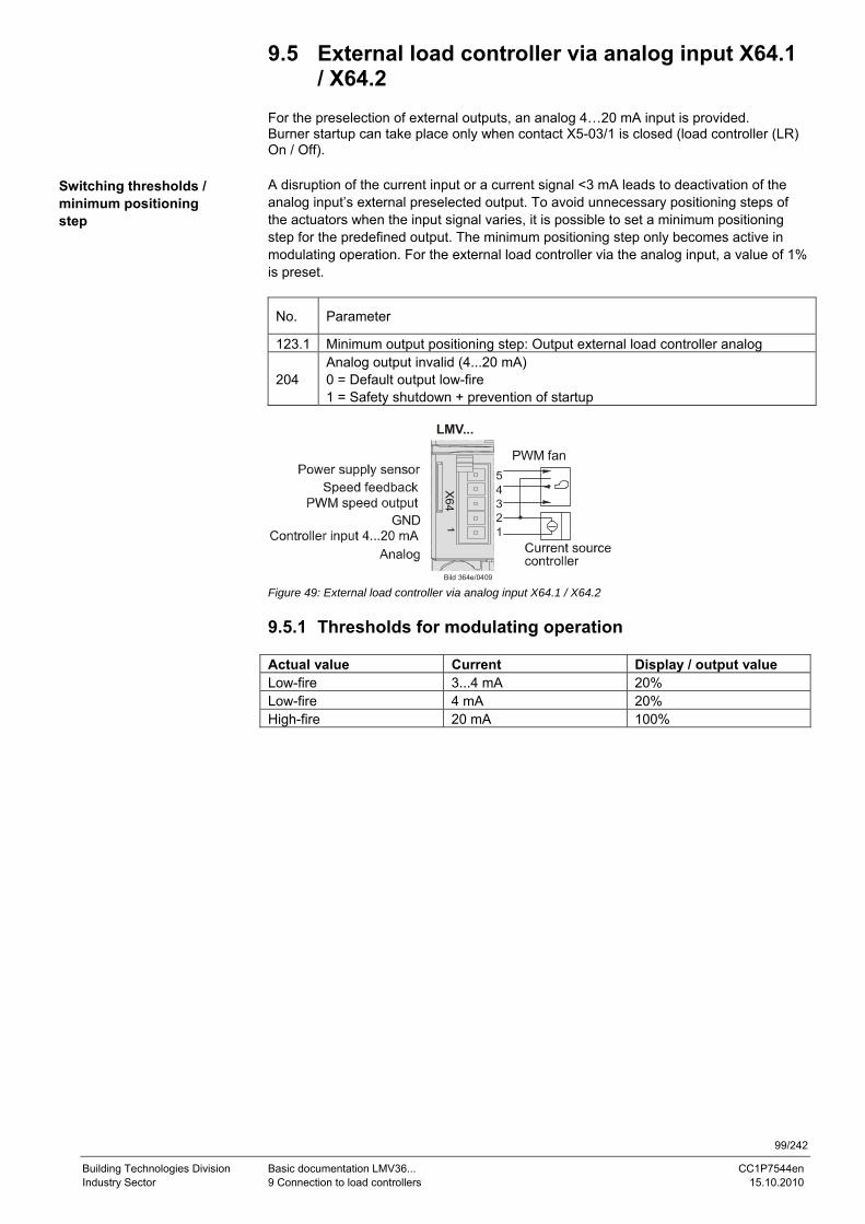
99/242
Building Technologies Division Basic documentation LMV36... CC1P7544en Industry Sector 9 Connection to load controllers 15.10.2010
9.5 External load controller via analog input X64.1 / X64.2
For the preselection of external outputs, an analog 4…20 mA input is provided. Burner startup can take place only when contact X5-03/1 is closed (load controller (LR) On / Off). A disruption of the current input or a current signal <3 mA leads to deactivation of the analog input’s external preselected output. To avoid unnecessary positioning steps of the actuators when the input signal varies, it is possible to set a minimum positioning step for the predefined output. The minimum positioning step only becomes active in modulating operation. For the external load controller via the analog input, a value of 1% is preset.
No. Parameter
123.1 Minimum output positioning step: Output external load controller analog
204 Analog output invalid (4...20 mA) 0 = Default output low-fire 1 = Safety shutdown + prevention of startup
X
64
GND
PWM fan
LMV...
Bild 364e/0409
54321
Figure 49: External load controller via analog input X64.1 / X64.2 9.5.1 Thresholds for modulating operation Actual value Current Display / output value Low-fire 3...4 mA 20% Low-fire 4 mA 20% High-fire 20 mA 100%
Switching thresholds / minimum positioning step
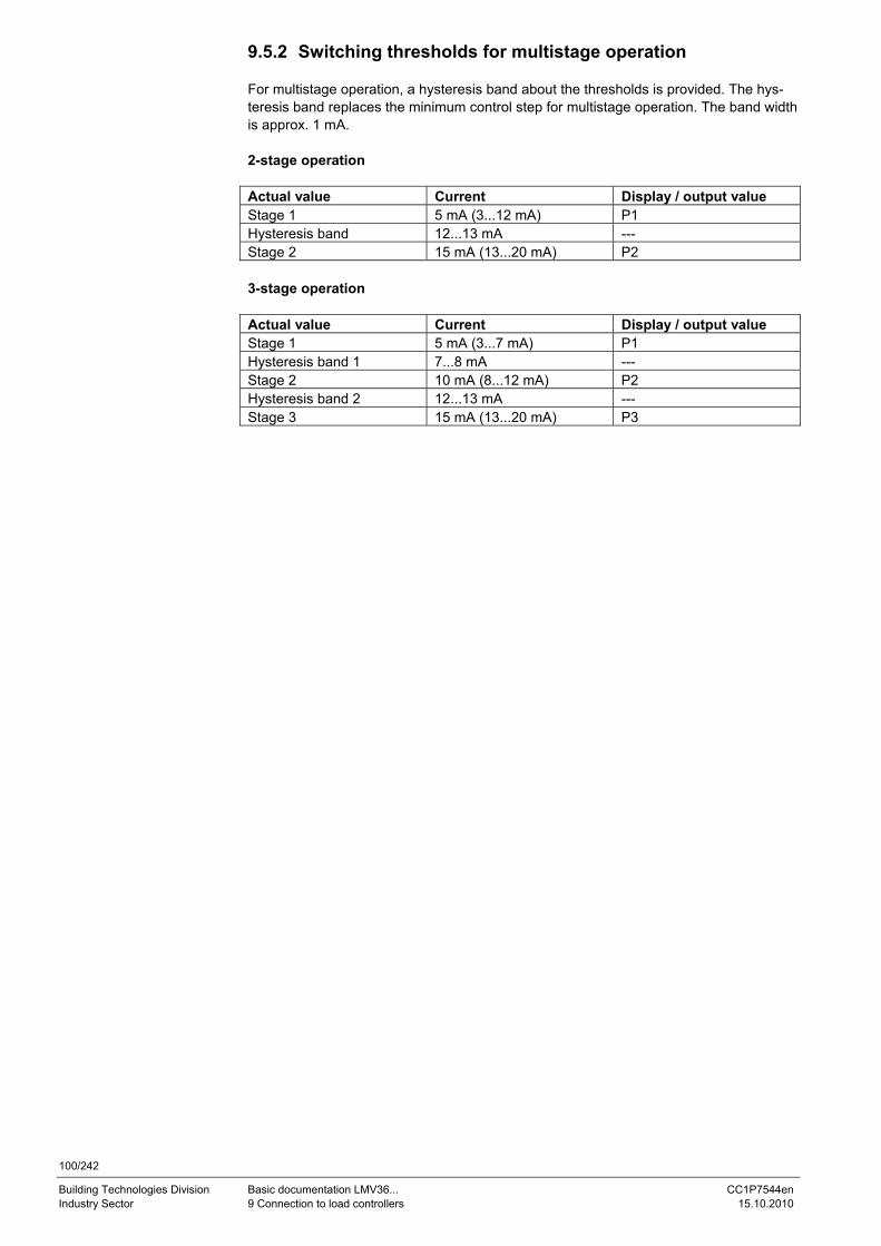
100/242
Building Technologies Division Basic documentation LMV36... CC1P7544en Industry Sector 9 Connection to load controllers 15.10.2010
9.5.2 Switching thresholds for multistage operation For multistage operation, a hysteresis band about the thresholds is provided. The hys-teresis band replaces the minimum control step for multistage operation. The band width is approx. 1 mA. 2-stage operation Actual value Current Display / output value Stage 1 5 mA (3...12 mA) P1 Hysteresis band 12...13 mA --- Stage 2 15 mA (13...20 mA) P2 3-stage operation Actual value Current Display / output value Stage 1 5 mA (3...7 mA) P1 Hysteresis band 1 7...8 mA --- Stage 2 10 mA (8...12 mA) P2 Hysteresis band 2 12...13 mA --- Stage 3 15 mA (13...20 mA) P3
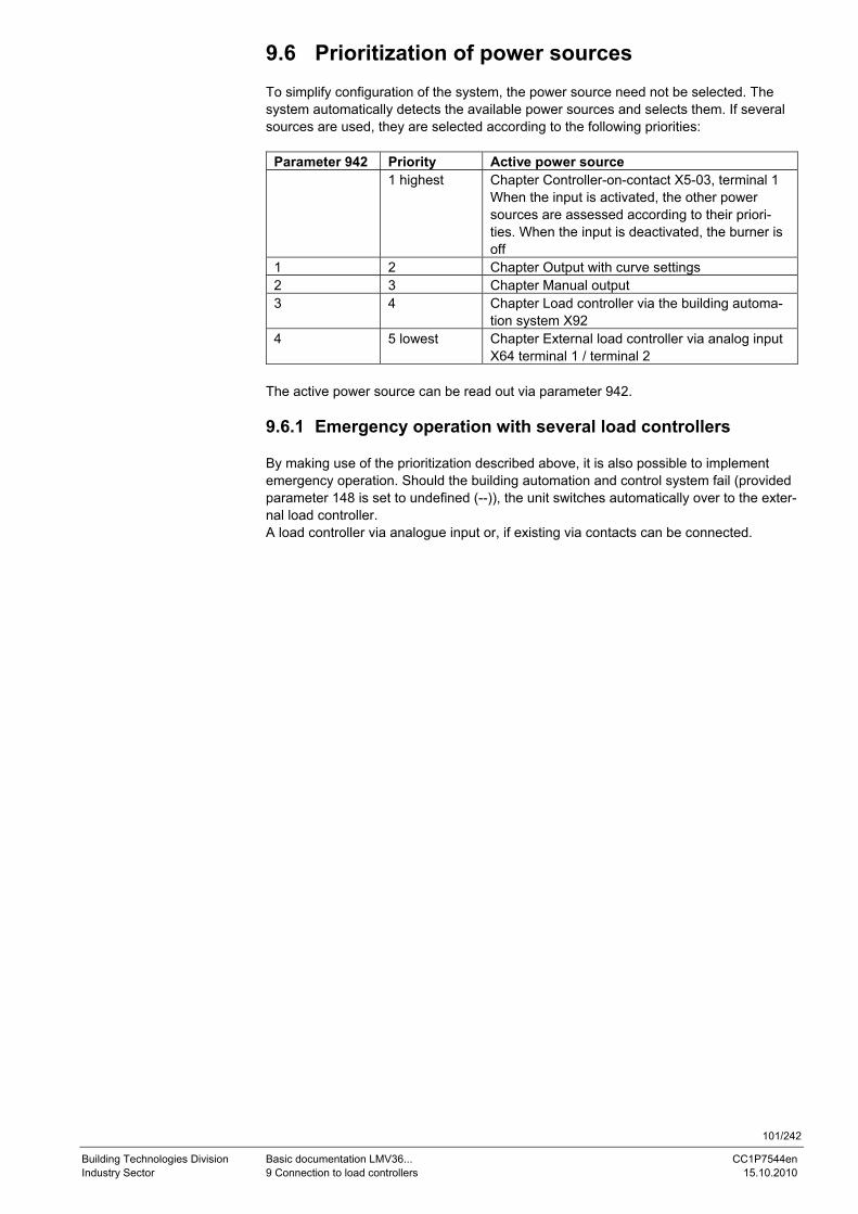
101/242
Building Technologies Division Basic documentation LMV36... CC1P7544en Industry Sector 9 Connection to load controllers 15.10.2010
9.6 Prioritization of power sources To simplify configuration of the system, the power source need not be selected. The system automatically detects the available power sources and selects them. If several sources are used, they are selected according to the following priorities:
Parameter 942 Priority Active power source 1 highest Chapter Controller-on-contact X5-03, terminal 1
When the input is activated, the other power sources are assessed according to their priori-ties. When the input is deactivated, the burner is off
1 2 Chapter Output with curve settings 2 3 Chapter Manual output 3 4 Chapter Load controller via the building automa-
tion system X92 4 5 lowest Chapter External load controller via analog input
X64 terminal 1 / terminal 2 The active power source can be read out via parameter 942. 9.6.1 Emergency operation with several load controllers By making use of the prioritization described above, it is also possible to implement emergency operation. Should the building automation and control system fail (provided parameter 148 is set to undefined (--)), the unit switches automatically over to the exter-nal load controller. A load controller via analogue input or, if existing via contacts can be connected.

102/242
Building Technologies Division Basic documentation LMV36... CC1P7544en Industry Sector 10 Electronic fuel-air ratio control 15.10.2010
10 Electronic fuel-air ratio control
10.1 General Electronic air-fuel ratio control is used to control the burner’s actuators depending on burner output. It is possible to connect 2 actuators and, optionally, 1 VSD. Resolution is 0.1° with the actuators and 0.1% with the VSD. Output can be regulated in increments of 0.1% in modulating mode or with a maximum of 3 stages in multistage mode. To reduce the electric power required for the actuators, they are never operated simul-taneously, but in successive order, or alternately.
10.2 Behavior outside the operating positions Outside their operating positions, the actuators approach the different positions in suc-cessive order. The program phase determines the position to be approached. 10.2.1 Traveling speed The actuators’ traveling speed is fixed at 5 seconds for covering a positioning angle of 90°. The ramp speed of the VSD can be adjusted separately for higher and lower speeds.
No. Parameter
522 Ramp up 523 Ramp down
The setting also applies to the operating position (refer to chapter Operating position). 10.2.2 Home position This position is approached in the Home run (10), Standby (12) and Lockout position (00) phases. The position can be set via the following parameters:
Parameter Actuator 501.00 No-flame positions fuel actuator: Home position 502.00 No-flame positions air actuator: Home position 503.00 No-flame speeds VSD: No-load speed 504.00 Fuel 1: No-flame positions fuel actuator: Home position 505.00 Fuel 1: No-flame positions air actuator: Home position 506.00 Fuel 1: No-flame speeds VSD: No-load speed
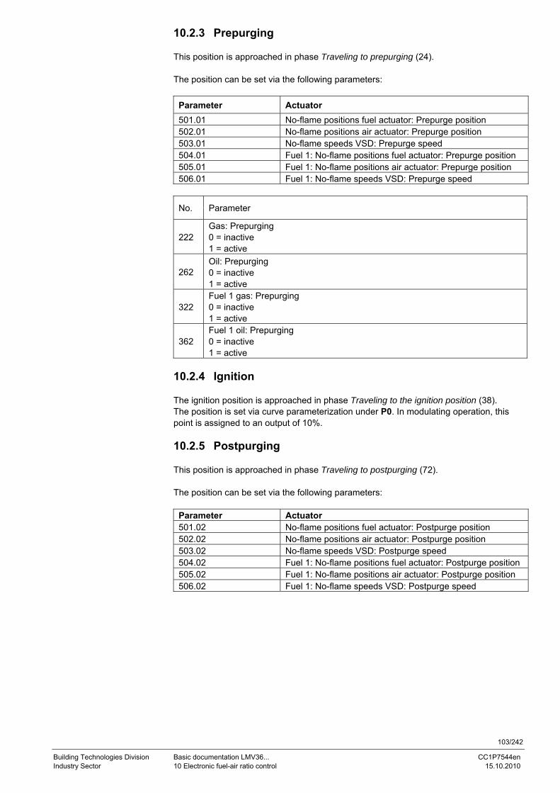
103/242
Building Technologies Division Basic documentation LMV36... CC1P7544en Industry Sector 10 Electronic fuel-air ratio control 15.10.2010
10.2.3 Prepurging This position is approached in phase Traveling to prepurging (24). The position can be set via the following parameters:
Parameter Actuator 501.01 No-flame positions fuel actuator: Prepurge position 502.01 No-flame positions air actuator: Prepurge position 503.01 No-flame speeds VSD: Prepurge speed 504.01 Fuel 1: No-flame positions fuel actuator: Prepurge position 505.01 Fuel 1: No-flame positions air actuator: Prepurge position 506.01 Fuel 1: No-flame speeds VSD: Prepurge speed
No. Parameter
222 Gas: Prepurging 0 = inactive 1 = active
262 Oil: Prepurging 0 = inactive 1 = active
322 Fuel 1 gas: Prepurging 0 = inactive 1 = active
362 Fuel 1 oil: Prepurging 0 = inactive 1 = active
10.2.4 Ignition The ignition position is approached in phase Traveling to the ignition position (38). The position is set via curve parameterization under P0. In modulating operation, this point is assigned to an output of 10%. 10.2.5 Postpurging This position is approached in phase Traveling to postpurging (72). The position can be set via the following parameters:
Parameter Actuator 501.02 No-flame positions fuel actuator: Postpurge position 502.02 No-flame positions air actuator: Postpurge position 503.02 No-flame speeds VSD: Postpurge speed 504.02 Fuel 1: No-flame positions fuel actuator: Postpurge position 505.02 Fuel 1: No-flame positions air actuator: Postpurge position 506.02 Fuel 1: No-flame speeds VSD: Postpurge speed
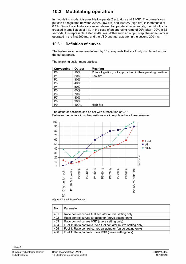
104/242
Building Technologies Division Basic documentation LMV36... CC1P7544en Industry Sector 10 Electronic fuel-air ratio control 15.10.2010
10.3 Modulating operation In modulating mode, it is possible to operate 2 actuators and 1 VSD. The burner‘s out-put can be regulated between 20.0% (low-fire) and 100.0% (high-fire) in increments of 0.1%. Since the actuators are never allowed to operate simultaneously, the output is in-creased in small steps of 1%. In the case of an operating ramp of 20% after 100% in 32 seconds, this represents 1 step in 400 ms. Within such an output step, the air actuator is operated in the first 200 ms, and the VSD and fuel actuator in the second 200 ms. 10.3.1 Definition of curves The fuel-air ratio curves are defined by 10 curvepoints that are firmly distributed across the output range. The following assignment applies:
Curvepoint Output Meaning P0 10% Point of ignition, not approached in the operating position P1 20% Low-fire P2 30% P3 40% P4 50% P5 60% P6 70% P7 80% P8 90% P9 100% High-fire
The actuator positions can be set with a resolution of 0.1°. Between the curvepoints, the positions are interpolated in a linear manner.
FuelAirVSD
100908070605040302010
0
P0
10 %
Igni
tion
poin
t
P1 2
0 %
Low
-fire
P2
30 %
P3
40 %
P4
50 %
P5
60 %
P6
70 %
P7
80 %
P8
90 %
P9
100
% H
igh-
fire
Bild
385
e/11
09
Figure 50: Definition of curves
No. Parameter
401 Ratio control curves fuel actuator (curve setting only) 402 Ratio control curves air actuator (curve setting only) 403 Ratio control curves VSD (curve setting only) 404 Fuel 1: Ratio control curves fuel actuator (curve setting only) 405 Fuel 1: Ratio control curves air actuator (curve setting only) 406 Fuel 1: Ratio control curves VSD (curve setting only)
105/242
Building Technologies Division Basic documentation LMV36... CC1P7544en Industry Sector 10 Electronic fuel-air ratio control 15.10.2010
10.3.2 Traveling speed/maximum curve slope The time required for modulating from low-fire to high-fire is 32 seconds. In connection with the actuator’s ramp in the basic unit, the following positioning angles or speed changes between maximum 2 curvepoints can be covered:
Type of actuator Positioning speed Positioning angle Actuator 5 s / 90° 31° VSD 5 s / 100% 40% 10 s / 100% 20% 20 s / 100% 10%
No. Parameter
522 Ramp up 523 Ramp down
The setting also acts outside the operating position (refer to chapter Traveling speed). VSD Between the ignition time (P0) and the low-fire point (P1), a speed differential of up to 40% can be set for the VSD, independent of the selected ramp. This means that the pe-riod of time from ignition to low-fire can vary between 4…16 seconds (5 to 20 seconds ramp).
Error code
Diagnostic code
Meaning for the LMV36... system
84 Bit 0 Valency 1
VSD: Curve too steep in terms of ramp rate
Bit 1 Valency 2…3
Fuel actuator: Curve too steep in terms of ramp rate
Bit 2 Valency 4…7
Air actuator: Curve too steep in terms of ramp rate
The parameterized curve is steeper than permitted with the selected actuator speed.
10.3.3 Entering the running position The burner is ignited when ignition position P0 is reached. When entering operating pha-se 60, the actuators follow the defined curves until the low-fire position is reached (20% or parameter 545 / 565 – lower output limit). 10.3.4 Operating position As demanded by the load controller, the actuators are driven along the defined 20% and 100% curves. Point of ignition P0 can only be reached via the curve settings.
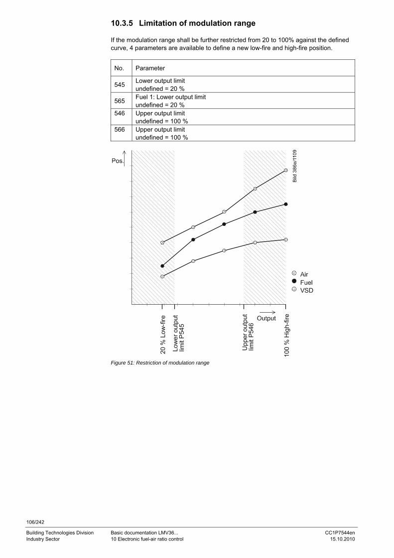
106/242
Building Technologies Division Basic documentation LMV36... CC1P7544en Industry Sector 10 Electronic fuel-air ratio control 15.10.2010
10.3.5 Limitation of modulation range If the modulation range shall be further restricted from 20 to 100% against the defined curve, 4 parameters are available to define a new low-fire and high-fire position.
No. Parameter
545 Lower output limit undefined = 20 %
565 Fuel 1: Lower output limit undefined = 20 %
546 Upper output limit undefined = 100 %
566 Upper output limit undefined = 100 %
20 %
Low
-fire
Low
er o
utpu
t lim
it P
545
Upp
er o
utpu
tlim
it P5
46
100
% H
igh-
fire
VSD
Figure 51: Restriction of modulation range
107/242
Building Technologies Division Basic documentation LMV36... CC1P7544en Industry Sector 10 Electronic fuel-air ratio control 15.10.2010
10.3.6 Setting the minimum and maximum output For changes regarding setting of the minimum and maximum output after the curve settings, note the following: After leaving the curve settings with completely defined curvepoints, proceed in modulating operation by setting the minimum / maximum output (parameters 546 / 545 or 566 / 565). In case of the warm setting, the parameterized output remains active until setting of the minimum / maximum output is completed. Any change to the minimum / maxi-mum output is included in the parameterized output. Automatic operation becomes active only after leaving the minimum / maximum output. As a result of this procedure, the system maintains the output set by the user, thus ensuring trouble-free setting of the minimum / maximum output. Advantages: - The actual output always corresponds to the currently parameterized minimum / maximum output or the system output resulting from the curve setting made last, which means that the output can be ascertained accurately and without interfer- ence - The load sources of low priority (contacts, analog input, BAC system output, manual output) are inactive - During the curve and the subsequent minimum/maximum output settings, the Manual OFF function is deactivated - Unambiguous and easy-to-understand behavior of the system Note If output limitation is not required, the minimum / maximum output need not be set. In that case, an undefined minimum / maximum output corresponds to a minimum output of 20% and a maximum output of 100%.
108/242
Building Technologies Division Basic documentation LMV36... CC1P7544en Industry Sector 10 Electronic fuel-air ratio control 15.10.2010
10.4 Multistage operation This operating mode is only available when firing on oil. There is a choice of 2-stage and 3-stage operation. Hence, the burner’s output can be modulated via 2 or 3 stages. Modulation is accomplished by adjustment of the air actuator or the VSD and by switch-ing the fuel valves for adjusting the amount of fuel. 10.4.1 Definition of curves Fuel-air ratio control is defined via the 2 or 3 static output points. To switch the valves on and off, switch-on and switch-off points must be defined. The following assignments apply:
Curve- point
Meaning Valve
P0 Point of ignition (not approached in the operating position) V1 P1 Stage 1 V1 P2on Switch-on point stage 2. When the angle exceeds this point, the
fuel valve for the second stage is switched on V1
P2_d Presetting of point P2 with no approach V1 P2 Stage 2 V2 P2of Switch-off point stage 2. When the angle falls below this point, the
fuel valve for the second stage is switched off V2
P3on Switch-on point stage 3. When the angle exceeds this point, the fuel valve for the third stage is switched on
V2
P3_d Presetting of point P3 with no approach V2 P3 Stage 3 V3 P3of Switch-off point stage 3. When the angle falls below this point, the
fuel valve for the third stage is switched off V3
The actuator positions can be set with a resolution of 0.1°, the speeds with a resolution of 0.1%. 10.4.2 Traveling speed The air actuator or the VSD is operated like outside the operating position. The defined ramp speeds are used. The traveling speed of the actuators is fixed at 5 seconds for a positioning angle of 90°. The speed of the VSD can be adjusted separately for speed increase or decrease.
No. Parameter
522 Ramp up 523 Ramp down
The setting also acts outside the operating position.
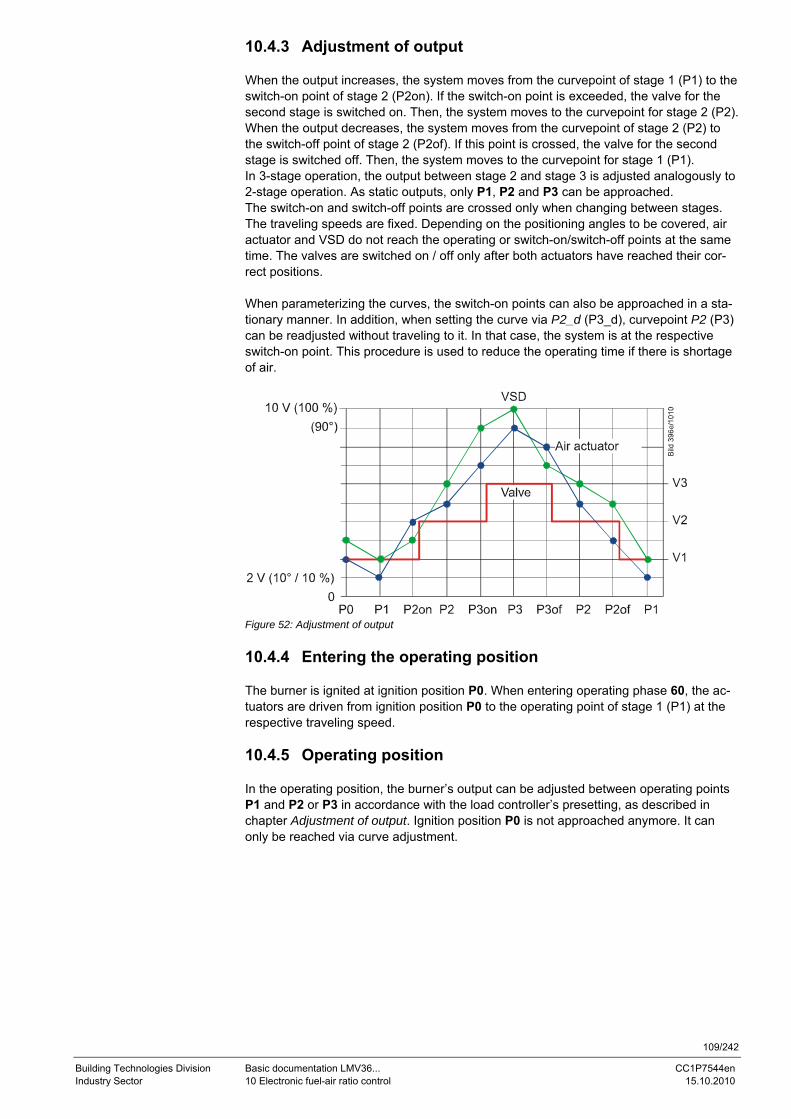
109/242
Building Technologies Division Basic documentation LMV36... CC1P7544en Industry Sector 10 Electronic fuel-air ratio control 15.10.2010
10.4.3 Adjustment of output When the output increases, the system moves from the curvepoint of stage 1 (P1) to the switch-on point of stage 2 (P2on). If the switch-on point is exceeded, the valve for the second stage is switched on. Then, the system moves to the curvepoint for stage 2 (P2). When the output decreases, the system moves from the curvepoint of stage 2 (P2) to the switch-off point of stage 2 (P2of). If this point is crossed, the valve for the second stage is switched off. Then, the system moves to the curvepoint for stage 1 (P1). In 3-stage operation, the output between stage 2 and stage 3 is adjusted analogously to 2-stage operation. As static outputs, only P1, P2 and P3 can be approached. The switch-on and switch-off points are crossed only when changing between stages. The traveling speeds are fixed. Depending on the positioning angles to be covered, air actuator and VSD do not reach the operating or switch-on/switch-off points at the same time. The valves are switched on / off only after both actuators have reached their cor-rect positions. When parameterizing the curves, the switch-on points can also be approached in a sta-tionary manner. In addition, when setting the curve via P2_d (P3_d), curvepoint P2 (P3) can be readjusted without traveling to it. In that case, the system is at the respective switch-on point. This procedure is used to reduce the operating time if there is shortage of air.
Figure 52: Adjustment of output 10.4.4 Entering the operating position The burner is ignited at ignition position P0. When entering operating phase 60, the ac-tuators are driven from ignition position P0 to the operating point of stage 1 (P1) at the respective traveling speed. 10.4.5 Operating position In the operating position, the burner’s output can be adjusted between operating points P1 and P2 or P3 in accordance with the load controller’s presetting, as described in chapter Adjustment of output. Ignition position P0 is not approached anymore. It can only be reached via curve adjustment.
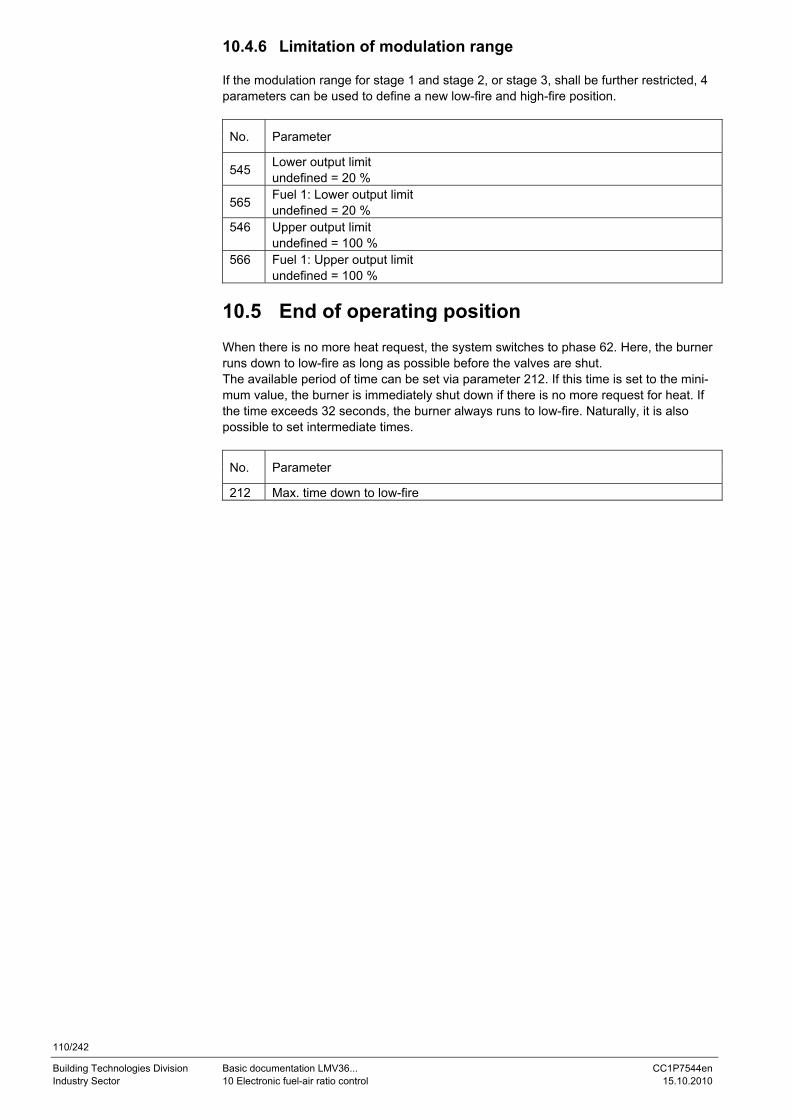
110/242
Building Technologies Division Basic documentation LMV36... CC1P7544en Industry Sector 10 Electronic fuel-air ratio control 15.10.2010
10.4.6 Limitation of modulation range If the modulation range for stage 1 and stage 2, or stage 3, shall be further restricted, 4 parameters can be used to define a new low-fire and high-fire position.
No. Parameter
545 Lower output limit undefined = 20 %
565 Fuel 1: Lower output limit undefined = 20 %
546 Upper output limit undefined = 100 %
566 Fuel 1: Upper output limit undefined = 100 %
10.5 End of operating position When there is no more heat request, the system switches to phase 62. Here, the burner runs down to low-fire as long as possible before the valves are shut. The available period of time can be set via parameter 212. If this time is set to the mini-mum value, the burner is immediately shut down if there is no more request for heat. If the time exceeds 32 seconds, the burner always runs to low-fire. Naturally, it is also possible to set intermediate times.
No. Parameter
212 Max. time down to low-fire
111/242
Building Technologies Division Basic documentation LMV36... CC1P7544en Industry Sector 10 Electronic fuel-air ratio control 15.10.2010
10.6 Notes on settings and parameter settings • When making the settings for the electronic fuel-air ratio control system integrated
in the LMV36..., it must be ensured that sufficient amounts of excess air are avail-able because over a period of time, the flue gas values are impacted by a number of factors, such as air density, wear of actuators and controlling elements, etc. For this reason, the flue gas values initially set must be checked at regular intervals
• To safeguard against accidental or unauthorized transfer of parameters from the pa-rameter backup of the ACS410 to the LMV36... basic unit, the OEM (burner or boiler manufacturer) must enter an individual burner identification for every burner. Only when this requirement is satisfied does the LMV36... system make certain that the ACS410 does not transfer a parameter set from a plant (with unsuited and pos-sibly dangerous parameter values) to the LMV36... basic unit
• With the LMV36..., it should be noted that the unit’s characteristics are determined primarily by the parameter settings and not so much by the type of unit. This means that – among other considerations – the parameter settings must always be checked prior to commissioning the plant, and that the LMV36... must never be transferred from one plant to another without adapting its parameters to the new plant
• When using the ACS410 PC software, the safety notes given in the relevant Operat-ing Instructions (J7352) must also be observed
• The parameter level is password-protected. The OEM assigns individual passwords to the parameter levels he can access. The unit is supplied with default passwords entered by Siemens; they must be changed by the OEM. These passwords are con-fidential and may be assigned to authorized personnel only
• The responsibility for setting parameters is assumed by the person who, in accor-dance with the access rights, has made changes on the respective setting level
In particular, the OEM assumes responsibility for the correct parameter settings in compliance with the standards covering the specific applications (e.g. EN 676, EN 267, EN 1643, etc.).
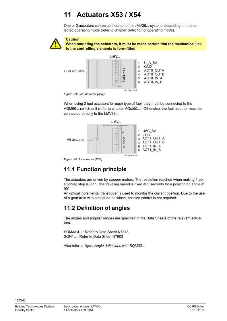
112/242
Building Technologies Division Basic documentation LMV36... CC1P7544en Industry Sector 11 Actuators X53 / X54 15.10.2010
11 Actuators X53 / X54 One or 2 actuators can be connected to the LMV36... system, depending on the se-lected operating mode (refer to chapter Selection of operating mode).
Caution! When mounting the actuators, it must be made certain that the mechanical link to the controlling elements is form-fitted!
LMV...
Bild 324e/1010
Fuel actuator
FUE
L X
54
123456
U_A_SAGNDACT0_OUTAACT0_OUTBACT0_IN_AACT0_IN_B
Figure 53: Fuel actuator (X54) When using 2 fuel actuators for each type of fuel, they must be connected to the AGM60... switch unit (refer to chapter AGM60...). Otherwise, the fuel actuator must be connected directly to the LMV36...
LMV...
Bild 325e/1010
AIR
X53Air actuator ACT1_OUT_A
ACT1_OUT_BACT1_IN_AACT1_IN_B
123456
Figure 54: Air actuator (X53)
11.1 Function principle The actuators are driven by stepper motors. The resolution reached when making 1 po-sitioning step is 0.1°. The traveling speed is fixed at 5 seconds for a positioning angle of 90°. An optical incremental transducer is used to monitor the current position. Due to the use of a gear train with almost no backlash, position control is not required.
11.2 Definition of angles The angles and angular ranges are specified in the Data Sheets of the relevant actua-tors. SQM33.4…: Refer to Data Sheet N7813 SQN1…: Refer to Data Sheet N7803 Also refer to figure Angle definitions with SQM33...
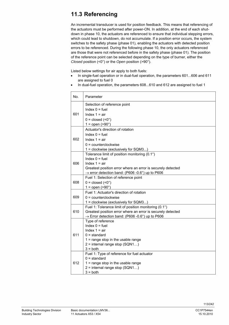
113/242
Building Technologies Division Basic documentation LMV36... CC1P7544en Industry Sector 11 Actuators X53 / X54 15.10.2010
11.3 Referencing An incremental transducer is used for position feedback. This means that referencing of the actuators must be performed after power-ON. In addition, at the end of each shut-down in phase 10, the actuators are referenced to ensure that individual stepping errors, which could lead to shutdown, do not accumulate. If a position error occurs, the system switches to the safety phase (phase 01), enabling the actuators with detected position errors to be referenced. During the following phase 10, the only actuators referenced are those that were not referenced before in the safety phase (phase 01). The position of the reference point can be selected depending on the type of burner, either the Closed position (<0°) or the Open position (>90°). Listed below settings for air apply to both fuels: • In single-fuel operation or in dual-fuel operation, the parameters 601...606 and 611
are assigned to fuel 0 • In dual-fuel operation, the parameters 608...610 and 612 are assigned to fuel 1
No. Parameter
601
Selection of reference point Index 0 = fuel Index 1 = air 0 = closed (<0°) 1 = open (>90°)
602
Actuator's direction of rotation Index 0 = fuel Index 1 = air 0 = counterclockwise 1 = clockwise (exclusively for SQM3...)
606
Tolerance limit of position monitoring (0.1°) Index 0 = fuel Index 1 = air Greatest position error where an error is securely detected → error detection band: (P606 -0.6°) up to P606
608 Fuel 1: Selection of reference point 0 = closed (<0°) 1 = open (>90°)
609 Fuel 1: Actuator's direction of rotation 0 = counterclockwise 1 = clockwise (exclusively for SQM3...)
610 Fuel 1: Tolerance limit of position monitoring (0.1°) Greatest position error where an error is securely detected → Error detection band: (P606 -0.6°) up to P606
611
Type of reference Index 0 = fuel Index 1 = air 0 = standard 1 = range stop in the usable range 2 = internal range stop (SQN1…) 3 = both
612
Fuel 1: Type of reference for fuel actuator 0 = standard 1 = range stop in the usable range 2 = internal range stop (SQN1…) 3 = both
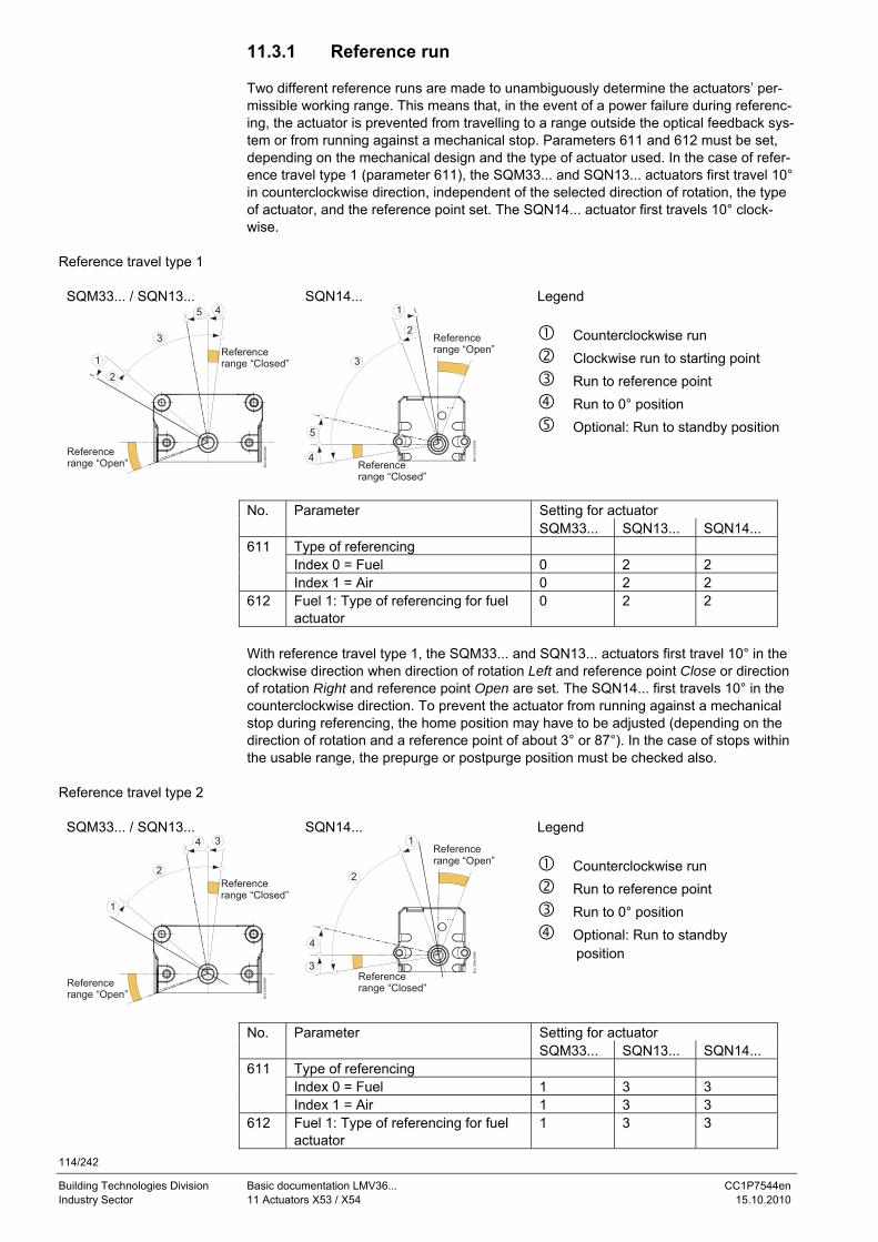
114/242
Building Technologies Division Basic documentation LMV36... CC1P7544en Industry Sector 11 Actuators X53 / X54 15.10.2010
11.3.1 Reference run Two different reference runs are made to unambiguously determine the actuators’ per-missible working range. This means that, in the event of a power failure during referenc-ing, the actuator is prevented from travelling to a range outside the optical feedback sys-tem or from running against a mechanical stop. Parameters 611 and 612 must be set, depending on the mechanical design and the type of actuator used. In the case of refer-ence travel type 1 (parameter 611), the SQM33... and SQN13... actuators first travel 10° in counterclockwise direction, independent of the selected direction of rotation, the type of actuator, and the reference point set. The SQN14... actuator first travels 10° clock-wise.
SQM33... / SQN13...
12
3
45
Referencerange “Open”
Referencerange “Closed”
SQN14... 1
2
3
4
5
Referencerange “Open”
Referencerange “Closed”
Legend
Counterclockwise run Clockwise run to starting point Run to reference point Run to 0° position Optional: Run to standby position
Setting for actuator No. Parameter SQM33... SQN13... SQN14...
611 Type of referencing Index 0 = Fuel 0 2 2 Index 1 = Air 0 2 2 612 Fuel 1: Type of referencing for fuel
actuator 0 2 2
With reference travel type 1, the SQM33... and SQN13... actuators first travel 10° in the clockwise direction when direction of rotation Left and reference point Close or direction of rotation Right and reference point Open are set. The SQN14... first travels 10° in the counterclockwise direction. To prevent the actuator from running against a mechanical stop during referencing, the home position may have to be adjusted (depending on the direction of rotation and a reference point of about 3° or 87°). In the case of stops within the usable range, the prepurge or postpurge position must be checked also.
SQM33... / SQN13...
1
2
34
Referencerange “Open”
Referencerange “Closed”
SQN14... 1
2
3
4
Referencerange “Open”
Referencerange “Closed”
Legend
Counterclockwise run Run to reference point Run to 0° position Optional: Run to standby
position
Setting for actuator No. Parameter SQM33... SQN13... SQN14...
611 Type of referencing Index 0 = Fuel 1 3 3 Index 1 = Air 1 3 3 612 Fuel 1: Type of referencing for fuel
actuator 1 3 3
Reference travel type 1
Reference travel type 2
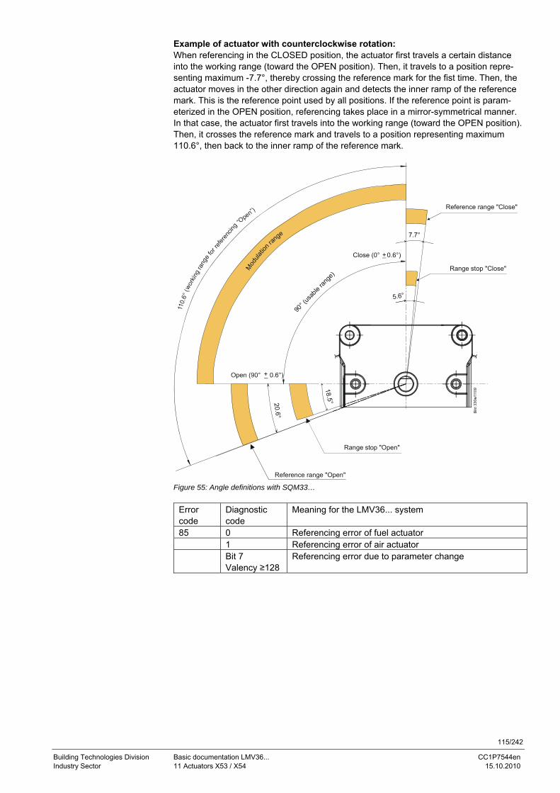
115/242
Building Technologies Division Basic documentation LMV36... CC1P7544en Industry Sector 11 Actuators X53 / X54 15.10.2010
Example of actuator with counterclockwise rotation: When referencing in the CLOSED position, the actuator first travels a certain distance into the working range (toward the OPEN position). Then, it travels to a position repre-senting maximum -7.7°, thereby crossing the reference mark for the fist time. Then, the actuator moves in the other direction again and detects the inner ramp of the reference mark. This is the reference point used by all positions. If the reference point is param-eterized in the OPEN position, referencing takes place in a mirror-symmetrical manner. In that case, the actuator first travels into the working range (toward the OPEN position). Then, it crosses the reference mark and travels to a position representing maximum 110.6°, then back to the inner ramp of the reference mark.
90° (
usab
le ran
ge)
Close (0° 0.6°)+
Reference range "Close"
Range stop "Close"
Reference range "Open"
Mod
ulatio
n ran
ge
Range stop "Open"
18.5°20.6°
5.6°
7.7°
+
110.
6° (w
orkin
g ra
nge f
or re
feren
cing “
Open”)
Figure 55: Angle definitions with SQM33…
Error code
Diagnostic code
Meaning for the LMV36... system
85 0 Referencing error of fuel actuator 1 Referencing error of air actuator Bit 7
Valency ≥128 Referencing error due to parameter change
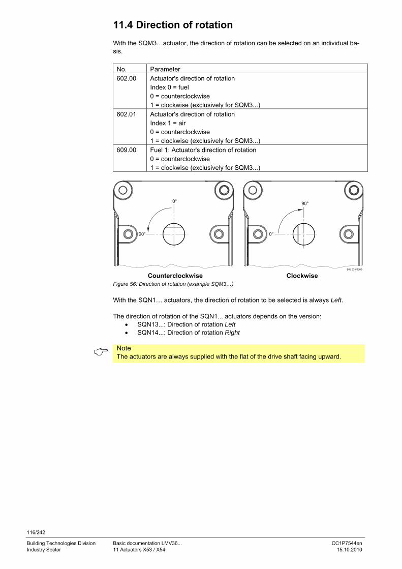
116/242
Building Technologies Division Basic documentation LMV36... CC1P7544en Industry Sector 11 Actuators X53 / X54 15.10.2010
11.4 Direction of rotation With the SQM3…actuator, the direction of rotation can be selected on an individual ba-sis.
No. Parameter 602.00 Actuator's direction of rotation
Index 0 = fuel 0 = counterclockwise 1 = clockwise (exclusively for SQM3...)
602.01 Actuator's direction of rotation Index 1 = air 0 = counterclockwise 1 = clockwise (exclusively for SQM3...)
609.00 Fuel 1: Actuator's direction of rotation 0 = counterclockwise 1 = clockwise (exclusively for SQM3...)
0°
0°
Counterclockwise Clockwise
Figure 56: Direction of rotation (example SQM3…) With the SQN1… actuators, the direction of rotation to be selected is always Left. The direction of rotation of the SQN1... actuators depends on the version:
• SQN13...: Direction of rotation Left • SQN14...: Direction of rotation Right
Note The actuators are always supplied with the flat of the drive shaft facing upward.
117/242
Building Technologies Division Basic documentation LMV36... CC1P7544en Industry Sector 11 Actuators X53 / X54 15.10.2010
11.5 Monitoring the actuator positions To monitor the actuator’s current positions, an optical incremental transducer with a resolution of 0.7° is used. The correct position of the drive shaft is ensured by compar-ing the motor steps made with the position obtained from the incremental transducer. Due to the different resolutions of motor steps and incremental transducer plus the se-lected tolerance band, the following error detection band is obtained. The position where – in the error detection band – shutdown takes place depends on the position currently required. For the default setting made in the factory, the error detection band is as follows:
Smallest position error where an error can be detected 0.8° Greatest position error where an error is securely detected (default setting parameter 606 or 610)
1.4°
The presetting of 1.4° (default setting, parameter 606 or 610) is suited for use with ac-tuators type SQM3... Note When using SQN1… actuators equipped with plastic gear trains, we recommend to change the preset values as follows: Product no. ValueSQN13.14... 1,7° SQN14.14... 1,7° SQN13.17... 2,2°
SQN14.17... 2,2° When referencing under output conditions, the resilience of the actuator’s gear train must also be taken into consideration: Product no. Resilience at max.
rated driving torque SQM33.41... 0.2° SQM33.51... 0.2° SQN13.14... 0.3° SQN13.17... 0.8° SQN14.14... 0.3° SQN14.17... 0.8°
The error detection time is <1 second.
Caution! This means that – for the design and setting of the burner – a position error re-sulting from the sum of… - greatest position error from which an error is detected in all positions, - resilience at the max. rated torque, and - mechanical influence from the link between actuator and regulating unit
(e.g. coupling) must not lead to a critical state in terms of safety.
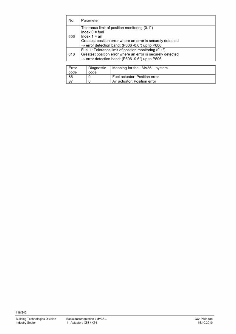
118/242
Building Technologies Division Basic documentation LMV36... CC1P7544en Industry Sector 11 Actuators X53 / X54 15.10.2010
No. Parameter
606
Tolerance limit of position monitoring (0.1°) Index 0 = fuel Index 1 = air Greatest position error where an error is securely detected → error detection band: (P606 -0.6°) up to P606
610 Fuel 1: Tolerance limit of position monitoring (0.1°) Greatest position error where an error is securely detected → error detection band: (P606 -0.6°) up to P606
Error code
Diagnostic code
Meaning for the LMV36... system
86 0 Fuel actuator: Position error 87 0 Air actuator: Position error
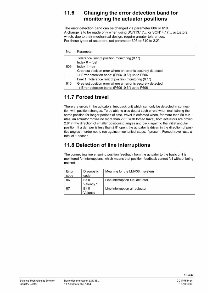
119/242
Building Technologies Division Basic documentation LMV36... CC1P7544en Industry Sector 11 Actuators X53 / X54 15.10.2010
11.6 Changing the error detection band for monitoring the actuator positions
The error detection band can be changed via parameter 606 or 610. A change is to be made only when using SQN13.17… or SQN14.17… actuators which, due to their mechanical design, require greater tolerances. For these types of actuators, set parameter 606 or 610 to 2.2°.
No. Parameter
606
Tolerance limit of position monitoring (0.1°) Index 0 = fuel Index 1 = air Greatest position error where an error is securely detected → Error detection band: (P606 -0.6°) up to P606
610 Fuel 1: Tolerance limit of position monitoring (0.1°) Greatest position error where an error is securely detected → Error detection band: (P606 -0.6°) up to P606
11.7 Forced travel There are errors in the actuators’ feedback unit which can only be detected in connec-tion with position changes. To be able to also detect such errors when maintaining the same position for longer periods of time, travel is enforced when, for more than 50 min-utes, an actuator moves no more than 2.8°. With forced travel, both actuators are driven 2.8° in the direction of smaller positioning angles and back again to the initial angular position. If a damper is less than 2.8° open, the actuator is driven in the direction of posi-tive angles in order not to run against mechanical stops, if present. Forced travel lasts a total of 1 second.
11.8 Detection of line interruptions The connecting line ensuring position feedback from the actuator to the basic unit is monitored for interruptions, which means that position feedback cannot fail without being noticed.
Error code
Diagnostic code
Meaning for the LMV36... system
86 Bit 0 Valency 1
Line interruption fuel actuator
87 Bit 0 Valency 1
Line interruption air actuator
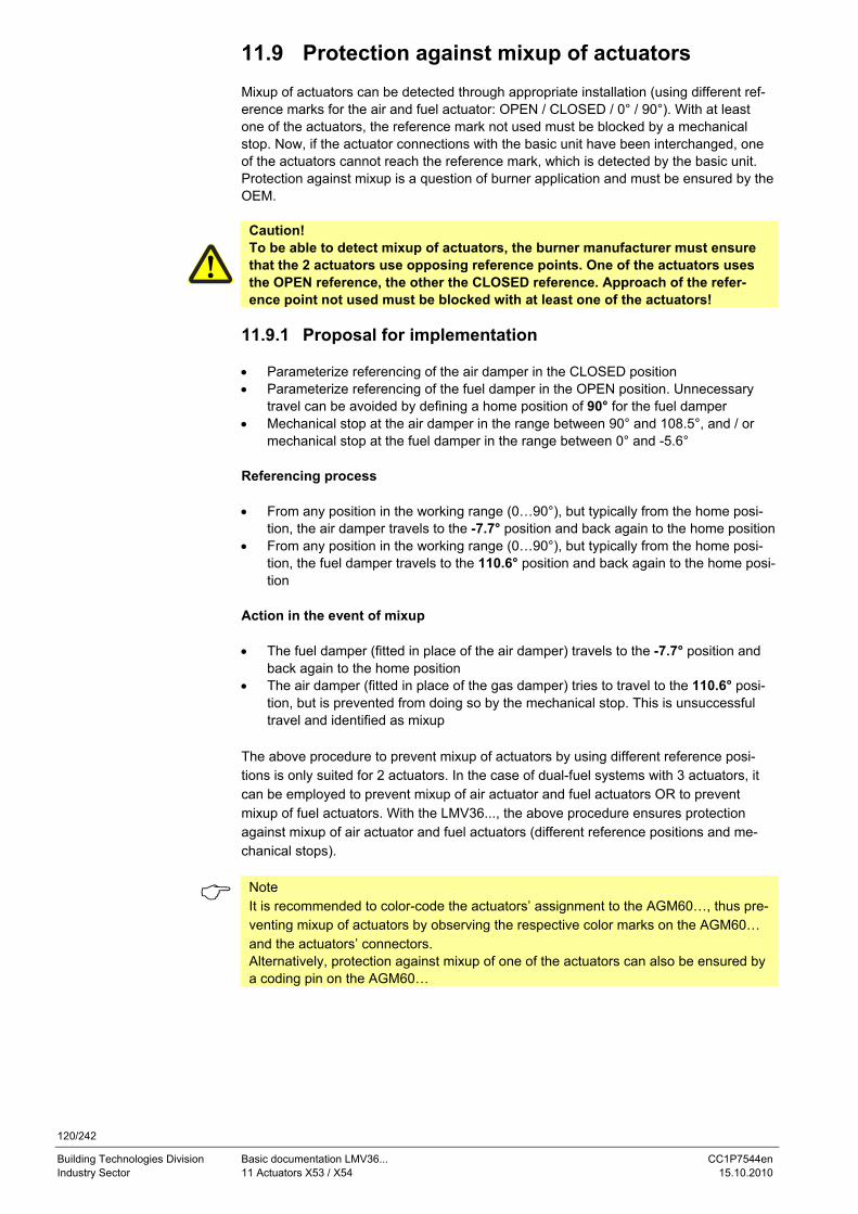
120/242
Building Technologies Division Basic documentation LMV36... CC1P7544en Industry Sector 11 Actuators X53 / X54 15.10.2010
11.9 Protection against mixup of actuators Mixup of actuators can be detected through appropriate installation (using different ref-erence marks for the air and fuel actuator: OPEN / CLOSED / 0° / 90°). With at least one of the actuators, the reference mark not used must be blocked by a mechanical stop. Now, if the actuator connections with the basic unit have been interchanged, one of the actuators cannot reach the reference mark, which is detected by the basic unit. Protection against mixup is a question of burner application and must be ensured by the OEM.
Caution! To be able to detect mixup of actuators, the burner manufacturer must ensure that the 2 actuators use opposing reference points. One of the actuators uses the OPEN reference, the other the CLOSED reference. Approach of the refer-ence point not used must be blocked with at least one of the actuators!
11.9.1 Proposal for implementation • Parameterize referencing of the air damper in the CLOSED position • Parameterize referencing of the fuel damper in the OPEN position. Unnecessary
travel can be avoided by defining a home position of 90° for the fuel damper • Mechanical stop at the air damper in the range between 90° and 108.5°, and / or
mechanical stop at the fuel damper in the range between 0° and -5.6° Referencing process • From any position in the working range (0…90°), but typically from the home posi-
tion, the air damper travels to the -7.7° position and back again to the home position • From any position in the working range (0…90°), but typically from the home posi-
tion, the fuel damper travels to the 110.6° position and back again to the home posi-tion
Action in the event of mixup • The fuel damper (fitted in place of the air damper) travels to the -7.7° position and
back again to the home position • The air damper (fitted in place of the gas damper) tries to travel to the 110.6° posi-
tion, but is prevented from doing so by the mechanical stop. This is unsuccessful travel and identified as mixup
The above procedure to prevent mixup of actuators by using different reference posi-tions is only suited for 2 actuators. In the case of dual-fuel systems with 3 actuators, it can be employed to prevent mixup of air actuator and fuel actuators OR to prevent mixup of fuel actuators. With the LMV36..., the above procedure ensures protection against mixup of air actuator and fuel actuators (different reference positions and me-chanical stops).
Note It is recommended to color-code the actuators’ assignment to the AGM60…, thus pre-venting mixup of actuators by observing the respective color marks on the AGM60… and the actuators’ connectors. Alternatively, protection against mixup of one of the actuators can also be ensured by a coding pin on the AGM60…
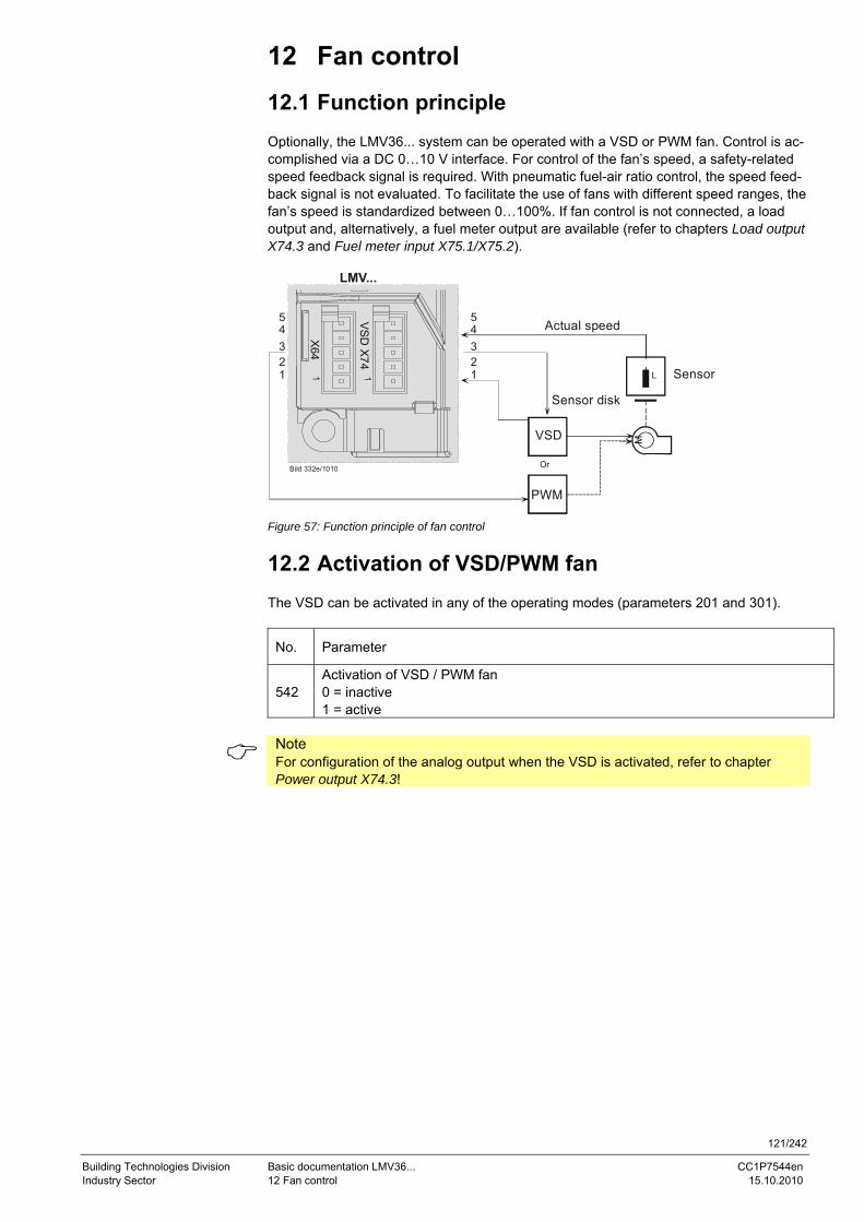
121/242
Building Technologies Division Basic documentation LMV36... CC1P7544en Industry Sector 12 Fan control 15.10.2010
12 Fan control
12.1 Function principle Optionally, the LMV36... system can be operated with a VSD or PWM fan. Control is ac-complished via a DC 0…10 V interface. For control of the fan’s speed, a safety-related speed feedback signal is required. With pneumatic fuel-air ratio control, the speed feed-back signal is not evaluated. To facilitate the use of fans with different speed ranges, the fan’s speed is standardized between 0…100%. If fan control is not connected, a load output and, alternatively, a fuel meter output are available (refer to chapters Load output X74.3 and Fuel meter input X75.1/X75.2).
LMV...
Bild 332e/1010
X64
VS
D X
74
MVSD
SensorL
Sensor disk
Actual speed
PWM
Or
45
321
45
321
Figure 57: Function principle of fan control
12.2 Activation of VSD/PWM fan The VSD can be activated in any of the operating modes (parameters 201 and 301).
No. Parameter
542 Activation of VSD / PWM fan 0 = inactive 1 = active
Note For configuration of the analog output when the VSD is activated, refer to chapter Power output X74.3!
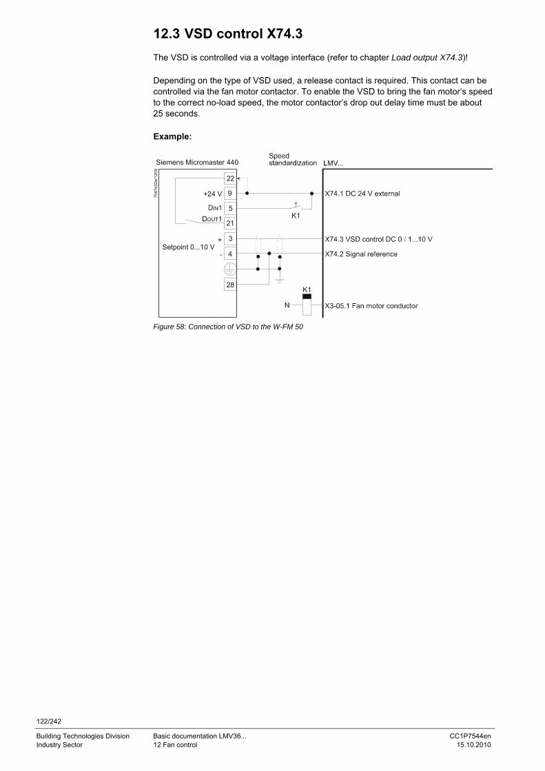
122/242
Building Technologies Division Basic documentation LMV36... CC1P7544en Industry Sector 12 Fan control 15.10.2010
12.3 VSD control X74.3 The VSD is controlled via a voltage interface (refer to chapter Load output X74.3)! Depending on the type of VSD used, a release contact is required. This contact can be controlled via the fan motor contactor. To enable the VSD to bring the fan motor’s speed to the correct no-load speed, the motor contactor’s drop out delay time must be about 25 seconds. Example:
K1
22
9
5
21
3
4
+24 V
+Setpoint 0...10 V
Siemens Micromaster 440
K1
28
Figure 58: Connection of VSD to the W-FM 50
123/242
Building Technologies Division Basic documentation LMV36... CC1P7544en Industry Sector 12 Fan control 15.10.2010
12.4 PWM fan control X64.3 The PWM fan is controlled via PWM voltage interface X64.3.
Caution! The use of PWM fans is only possible in connection with pneumatic air-fuel ra-tio control!
12.5 Safe separation of mains voltage and protec-tive extra low-voltage
Caution! All inputs and outputs of PWM fan control are designed for use with protective extra low-voltage. For this reason, strict separation from the mains voltage side must be ensured!
This necessitates an external power supply by the VSD or an external power pack (X74.1, X74.2).
Note Power must also be supplied via X74.1/2 in the case a PWM fan is used.
12.6 Ramp time The ramp time for fan control can be set separately for acceleration and deceleration (also refer to chapter Traveling speed/maximum curve slope).
No. Parameter
522 Ramp up 523 Ramp down
If shutdown occurs because the speed has not been reached, the VSD/fan motor might not be able to follow quickly enough the set ramp. Remedy: Shorten further the ramp of the VSD/fan motor or increase the ramp in the basic unit (parameters 522/523) (also refer to chapter Traveling speed/maximum curve slope).
Caution! The ramps parameterized for the VSD should be at least 20% shorter than the ramps in the LMV36...
Example: 10 s ramp LMV36... 8 s ramp VSD 5 s ramp LMV36... 4 s ramp VSD
For VSD operation
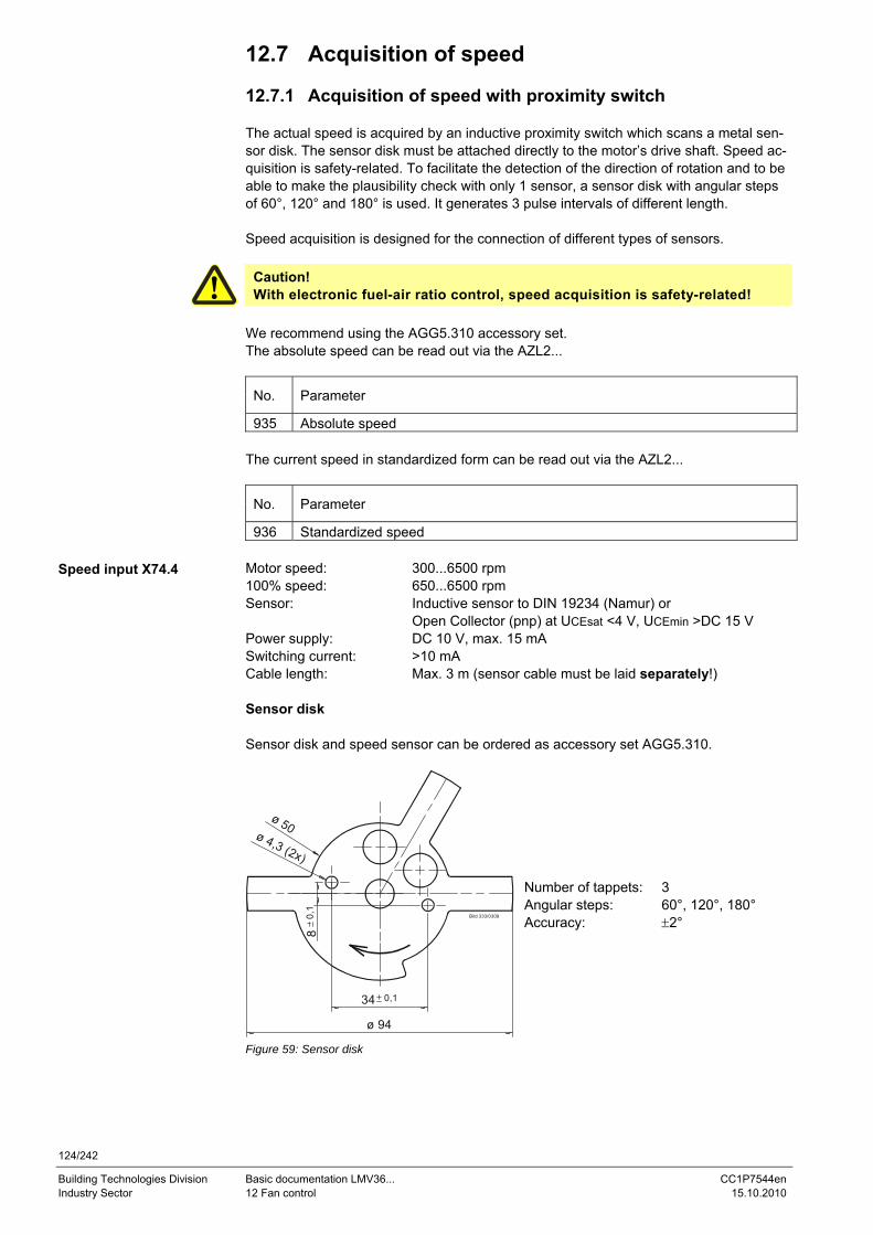
124/242
Building Technologies Division Basic documentation LMV36... CC1P7544en Industry Sector 12 Fan control 15.10.2010
12.7 Acquisition of speed 12.7.1 Acquisition of speed with proximity switch The actual speed is acquired by an inductive proximity switch which scans a metal sen-sor disk. The sensor disk must be attached directly to the motor’s drive shaft. Speed ac-quisition is safety-related. To facilitate the detection of the direction of rotation and to be able to make the plausibility check with only 1 sensor, a sensor disk with angular steps of 60°, 120° and 180° is used. It generates 3 pulse intervals of different length. Speed acquisition is designed for the connection of different types of sensors.
Caution! With electronic fuel-air ratio control, speed acquisition is safety-related!
We recommend using the AGG5.310 accessory set. The absolute speed can be read out via the AZL2...
No. Parameter
935 Absolute speed The current speed in standardized form can be read out via the AZL2...
No. Parameter
936 Standardized speed Motor speed: 300...6500 rpm 100% speed: 650...6500 rpm Sensor: Inductive sensor to DIN 19234 (Namur) or Open Collector (pnp) at UCEsat <4 V, UCEmin >DC 15 V Power supply: DC 10 V, max. 15 mA Switching current: >10 mA Cable length: Max. 3 m (sensor cable must be laid separately!) Sensor disk Sensor disk and speed sensor can be ordered as accessory set AGG5.310.
Bild 333/0309
ø 94
0,1
0,1
ø 50ø 4,3 (2x)
Number of tappets: 3 Angular steps: 60°, 120°, 180° Accuracy: ±2°
Figure 59: Sensor disk
Speed input X74.4
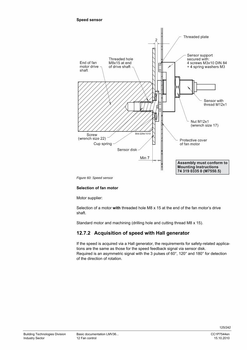
125/242
Building Technologies Division Basic documentation LMV36... CC1P7544en Industry Sector 12 Fan control 15.10.2010
Speed sensor
2
Figure 60: Speed sensor Selection of fan motor Motor supplier: Selection of a motor with threaded hole M8 x 15 at the end of the fan motor’s drive shaft. Standard motor and machining (drilling hole and cutting thread M8 x 15). 12.7.2 Acquisition of speed with Hall generator If the speed is acquired via a Hall generator, the requirements for safety-related applica-tions are the same as those for the speed feedback signal via sensor disk. Required is an asymmetric signal with the 3 pulses of 60°, 120° and 180° for detection of the direction of rotation.
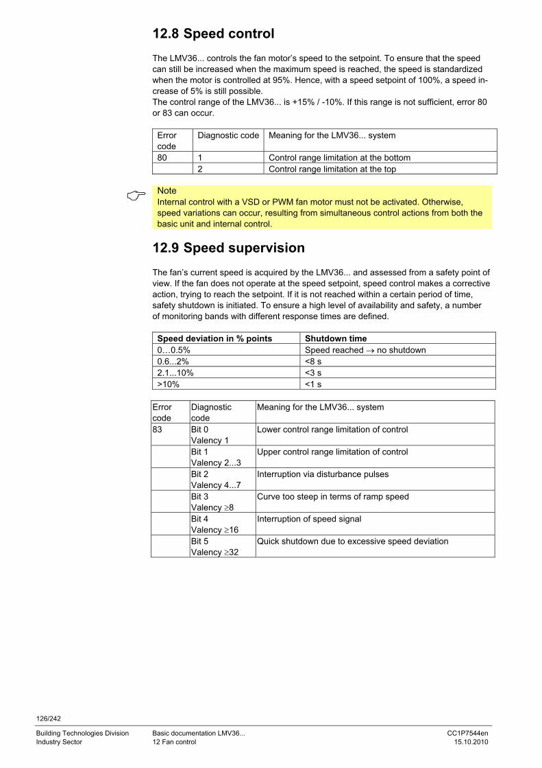
126/242
Building Technologies Division Basic documentation LMV36... CC1P7544en Industry Sector 12 Fan control 15.10.2010
12.8 Speed control The LMV36... controls the fan motor’s speed to the setpoint. To ensure that the speed can still be increased when the maximum speed is reached, the speed is standardized when the motor is controlled at 95%. Hence, with a speed setpoint of 100%, a speed in-crease of 5% is still possible. The control range of the LMV36... is +15% / -10%. If this range is not sufficient, error 80 or 83 can occur.
Error code
Diagnostic code Meaning for the LMV36... system
80 1 Control range limitation at the bottom 2 Control range limitation at the top
Note Internal control with a VSD or PWM fan motor must not be activated. Otherwise, speed variations can occur, resulting from simultaneous control actions from both the basic unit and internal control.
12.9 Speed supervision The fan’s current speed is acquired by the LMV36... and assessed from a safety point of view. If the fan does not operate at the speed setpoint, speed control makes a corrective action, trying to reach the setpoint. If it is not reached within a certain period of time, safety shutdown is initiated. To ensure a high level of availability and safety, a number of monitoring bands with different response times are defined.
Speed deviation in % points Shutdown time 0…0.5% Speed reached → no shutdown 0.6...2% <8 s 2.1...10% <3 s >10% <1 s
Error code
Diagnostic code
Meaning for the LMV36... system
83 Bit 0 Valency 1
Lower control range limitation of control
Bit 1 Valency 2...3
Upper control range limitation of control
Bit 2 Valency 4...7
Interruption via disturbance pulses
Bit 3 Valency ≥8
Curve too steep in terms of ramp speed
Bit 4 Valency ≥16
Interruption of speed signal
Bit 5 Valency ≥32
Quick shutdown due to excessive speed deviation
127/242
Building Technologies Division Basic documentation LMV36... CC1P7544en Industry Sector 12 Fan control 15.10.2010
12.10 Setting the parameters of the VSD If a control signal of 95% (9.5 V) is not sufficient for the burner to deliver its rated capac-ity, you can proceed as follows: - Set the maximum frequency to 105.3% of the motor’s rated speed In the case of a motor frequency of 50 Hz, this means: Set the maximum frequency of the VSD to 50 Hz x 1.053 = 52.6 Hz (on the VSD). - Then, standardize the speed (refer to chapter Standardization of speed) There is no risk of motor overload since only 95% of the maximum control signal is de-livered during standardization and – later in operation – the effective speed is controlled and monitored. Frequencies of between 50 Hz and 52.6 Hz are delivered only if these are needed for reaching the required speed due to increased output. - Set the ramp times of the VSD according to chapter Setting the ramp times
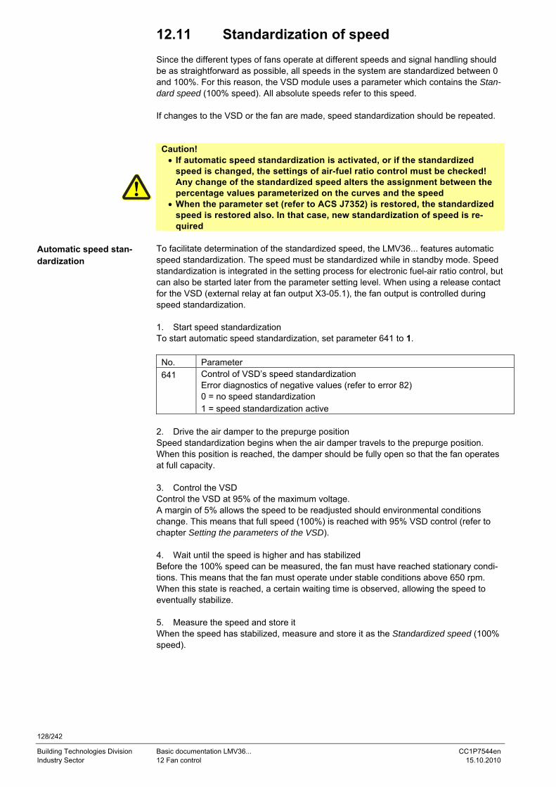
128/242
Building Technologies Division Basic documentation LMV36... CC1P7544en Industry Sector 12 Fan control 15.10.2010
12.11 Standardization of speed Since the different types of fans operate at different speeds and signal handling should be as straightforward as possible, all speeds in the system are standardized between 0 and 100%. For this reason, the VSD module uses a parameter which contains the Stan-dard speed (100% speed). All absolute speeds refer to this speed. If changes to the VSD or the fan are made, speed standardization should be repeated.
Caution! • If automatic speed standardization is activated, or if the standardized
speed is changed, the settings of air-fuel ratio control must be checked! Any change of the standardized speed alters the assignment between the percentage values parameterized on the curves and the speed
• When the parameter set (refer to ACS J7352) is restored, the standardized speed is restored also. In that case, new standardization of speed is re-quired
To facilitate determination of the standardized speed, the LMV36... features automatic speed standardization. The speed must be standardized while in standby mode. Speed standardization is integrated in the setting process for electronic fuel-air ratio control, but can also be started later from the parameter setting level. When using a release contact for the VSD (external relay at fan output X3-05.1), the fan output is controlled during speed standardization. 1. Start speed standardization To start automatic speed standardization, set parameter 641 to 1.
No. Parameter 641 Control of VSD’s speed standardization
Error diagnostics of negative values (refer to error 82) 0 = no speed standardization 1 = speed standardization active
2. Drive the air damper to the prepurge position Speed standardization begins when the air damper travels to the prepurge position. When this position is reached, the damper should be fully open so that the fan operates at full capacity. 3. Control the VSD Control the VSD at 95% of the maximum voltage. A margin of 5% allows the speed to be readjusted should environmental conditions change. This means that full speed (100%) is reached with 95% VSD control (refer to chapter Setting the parameters of the VSD). 4. Wait until the speed is higher and has stabilized Before the 100% speed can be measured, the fan must have reached stationary condi-tions. This means that the fan must operate under stable conditions above 650 rpm. When this state is reached, a certain waiting time is observed, allowing the speed to eventually stabilize. 5. Measure the speed and store it When the speed has stabilized, measure and store it as the Standardized speed (100% speed).
Automatic speed stan-dardization
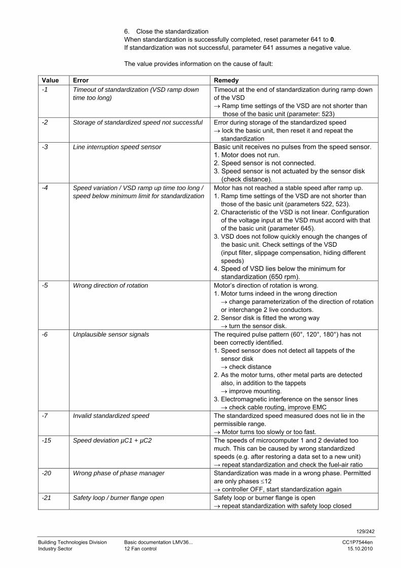
129/242
Building Technologies Division Basic documentation LMV36... CC1P7544en Industry Sector 12 Fan control 15.10.2010
6. Close the standardization When standardization is successfully completed, reset parameter 641 to 0. If standardization was not successful, parameter 641 assumes a negative value. The value provides information on the cause of fault:
Value Error Remedy -1 Timeout of standardization (VSD ramp down
time too long) Timeout at the end of standardization during ramp down of the VSD → Ramp time settings of the VSD are not shorter than those of the basic unit (parameter: 523)
-2 Storage of standardized speed not successful Error during storage of the standardized speed → lock the basic unit, then reset it and repeat the standardization
-3 Line interruption speed sensor Basic unit receives no pulses from the speed sensor. 1. Motor does not run. 2. Speed sensor is not connected. 3. Speed sensor is not actuated by the sensor disk (check distance).
-4 Speed variation / VSD ramp up time too long / speed below minimum limit for standardization
Motor has not reached a stable speed after ramp up. 1. Ramp time settings of the VSD are not shorter than those of the basic unit (parameters 522, 523). 2. Characteristic of the VSD is not linear. Configuration of the voltage input at the VSD must accord with that of the basic unit (parameter 645). 3. VSD does not follow quickly enough the changes of the basic unit. Check settings of the VSD (input filter, slippage compensation, hiding different speeds) 4. Speed of VSD lies below the minimum for standardization (650 rpm).
-5 Wrong direction of rotation Motor’s direction of rotation is wrong. 1. Motor turns indeed in the wrong direction → change parameterization of the direction of rotation or interchange 2 live conductors. 2. Sensor disk is fitted the wrong way → turn the sensor disk.
-6 Unplausible sensor signals The required pulse pattern (60°, 120°, 180°) has not been correctly identified. 1. Speed sensor does not detect all tappets of the sensor disk → check distance 2. As the motor turns, other metal parts are detected also, in addition to the tappets → improve mounting. 3. Electromagnetic interference on the sensor lines → check cable routing, improve EMC
-7 Invalid standardized speed The standardized speed measured does not lie in the permissible range. → Motor turns too slowly or too fast.
-15 Speed deviation µC1 + µC2 The speeds of microcomputer 1 and 2 deviated too much. This can be caused by wrong standardized speeds (e.g. after restoring a data set to a new unit) → repeat standardization and check the fuel-air ratio
-20 Wrong phase of phase manager Standardization was made in a wrong phase. Permitted are only phases ≤12 → controller OFF, start standardization again
-21 Safety loop / burner flange open Safety loop or burner flange is open → repeat standardization with safety loop closed
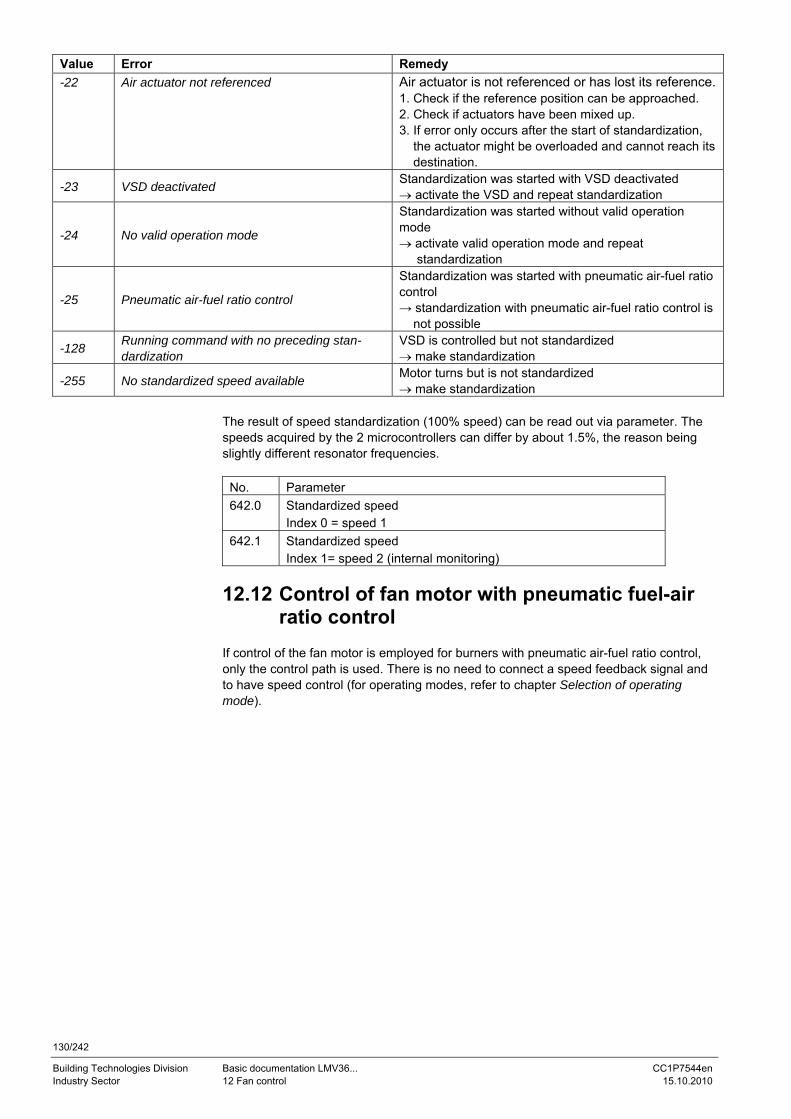
130/242
Building Technologies Division Basic documentation LMV36... CC1P7544en Industry Sector 12 Fan control 15.10.2010
Value Error Remedy -22 Air actuator not referenced Air actuator is not referenced or has lost its reference.
1. Check if the reference position can be approached. 2. Check if actuators have been mixed up. 3. If error only occurs after the start of standardization, the actuator might be overloaded and cannot reach its destination.
-23 VSD deactivated Standardization was started with VSD deactivated → activate the VSD and repeat standardization
-24 No valid operation mode
Standardization was started without valid operation mode → activate valid operation mode and repeat standardization
-25 Pneumatic air-fuel ratio control
Standardization was started with pneumatic air-fuel ratio control → standardization with pneumatic air-fuel ratio control is not possible
-128 Running command with no preceding stan-dardization
VSD is controlled but not standardized → make standardization
-255 No standardized speed available Motor turns but is not standardized → make standardization
The result of speed standardization (100% speed) can be read out via parameter. The speeds acquired by the 2 microcontrollers can differ by about 1.5%, the reason being slightly different resonator frequencies.
No. Parameter 642.0 Standardized speed
Index 0 = speed 1 642.1 Standardized speed
Index 1= speed 2 (internal monitoring)
12.12 Control of fan motor with pneumatic fuel-air ratio control
If control of the fan motor is employed for burners with pneumatic air-fuel ratio control, only the control path is used. There is no need to connect a speed feedback signal and to have speed control (for operating modes, refer to chapter Selection of operating mode).
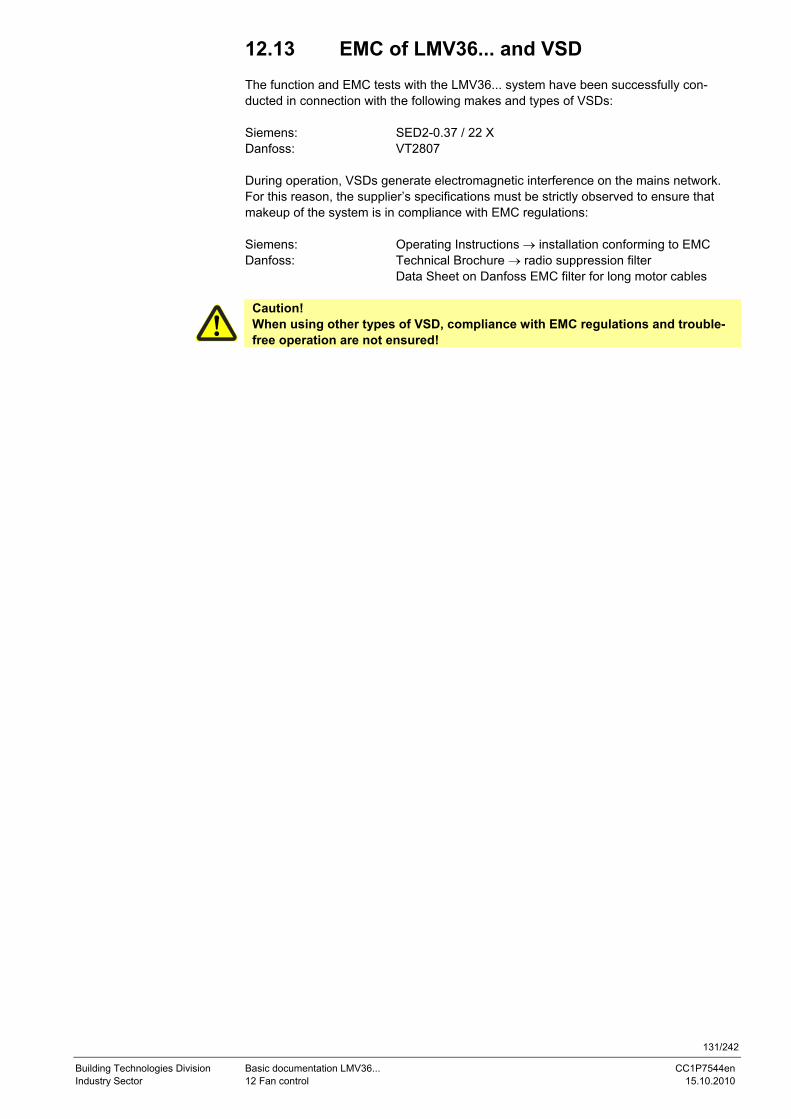
131/242
Building Technologies Division Basic documentation LMV36... CC1P7544en Industry Sector 12 Fan control 15.10.2010
12.13 EMC of LMV36... and VSD The function and EMC tests with the LMV36... system have been successfully con-ducted in connection with the following makes and types of VSDs: Siemens: SED2-0.37 / 22 X Danfoss: VT2807 During operation, VSDs generate electromagnetic interference on the mains network. For this reason, the supplier’s specifications must be strictly observed to ensure that makeup of the system is in compliance with EMC regulations: Siemens: Operating Instructions → installation conforming to EMC Danfoss: Technical Brochure → radio suppression filter Data Sheet on Danfoss EMC filter for long motor cables
Caution! When using other types of VSD, compliance with EMC regulations and trouble-free operation are not ensured!
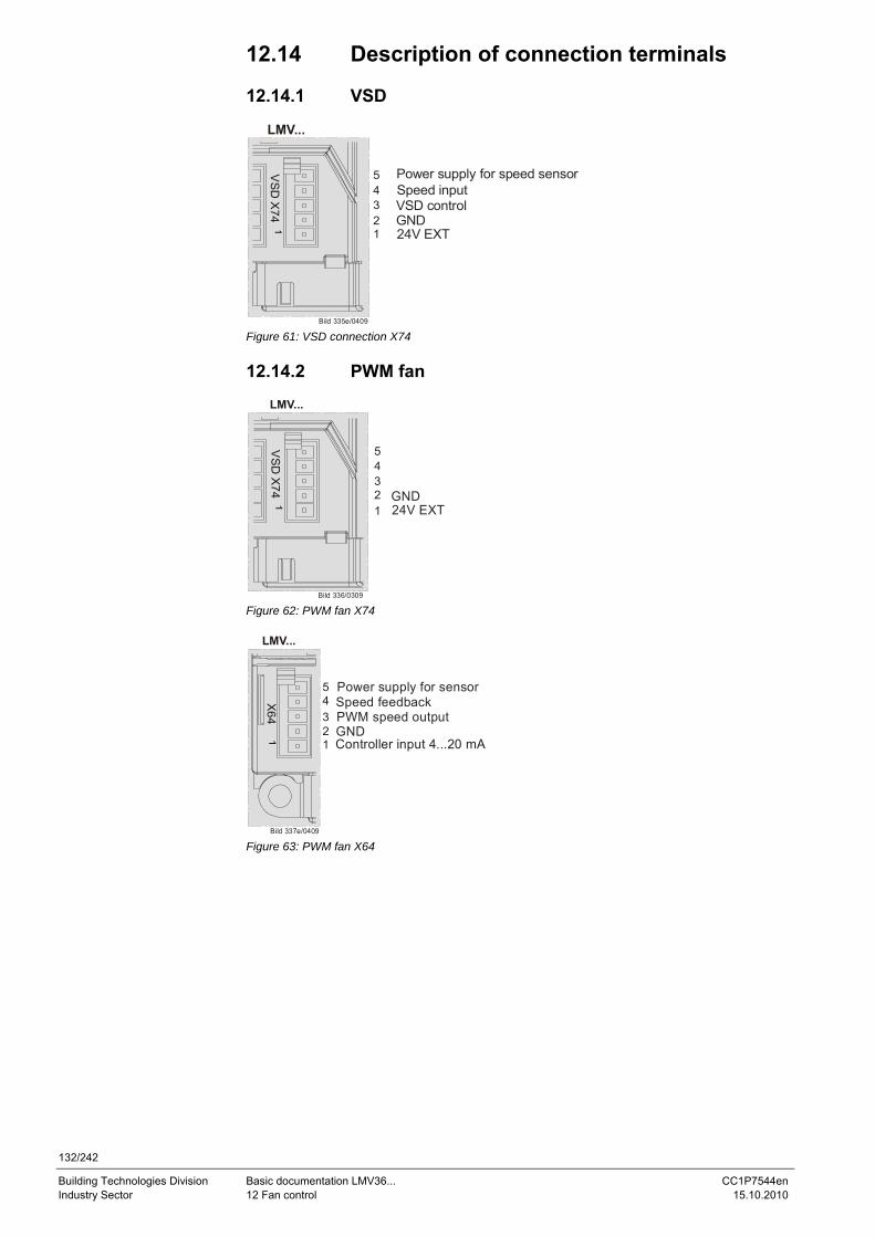
132/242
Building Technologies Division Basic documentation LMV36... CC1P7544en Industry Sector 12 Fan control 15.10.2010
12.14 Description of connection terminals 12.14.1 VSD
LMV...
Bild 335e/0409
VS
D X
74
24V EXTGNDVSD controlSpeed inputPower supply for speed sensor5
4321
Figure 61: VSD connection X74 12.14.2 PWM fan
LMV...
Bild 336/0309V
SD
X74
24V EXTGND
54321
Figure 62: PWM fan X74
LMV...
Bild 337e/0409
X64
GNDPWM speed outputSpeed feedbackPower supply for sensor5
4321 Controller input 4...20 mA
Figure 63: PWM fan X64
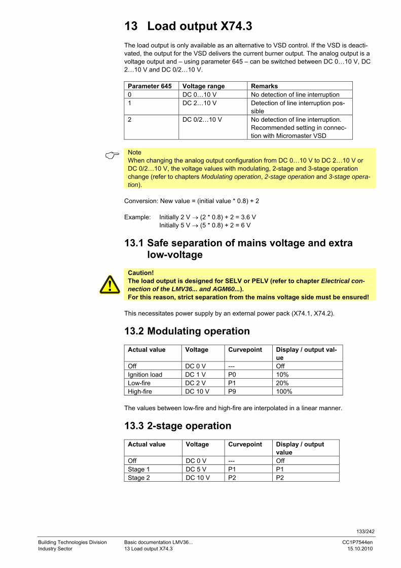
133/242
Building Technologies Division Basic documentation LMV36... CC1P7544en Industry Sector 13 Load output X74.3 15.10.2010
13 Load output X74.3 The load output is only available as an alternative to VSD control. If the VSD is deacti-vated, the output for the VSD delivers the current burner output. The analog output is a voltage output and – using parameter 645 – can be switched between DC 0…10 V, DC 2…10 V and DC 0/2…10 V.
Parameter 645 Voltage range Remarks 0 DC 0…10 V No detection of line interruption 1 DC 2…10 V Detection of line interruption pos-
sible 2 DC 0/2…10 V No detection of line interruption.
Recommended setting in connec-tion with Micromaster VSD
Note When changing the analog output configuration from DC 0…10 V to DC 2…10 V or DC 0/2…10 V, the voltage values with modulating, 2-stage and 3-stage operation change (refer to chapters Modulating operation, 2-stage operation and 3-stage opera-tion).
Conversion: New value = (initial value * 0.8) + 2 Example: Initially 2 V → (2 * 0.8) + 2 = 3.6 V Initially 5 V → (5 * 0.8) + 2 = 6 V
13.1 Safe separation of mains voltage and extra low-voltage
Caution! The load output is designed for SELV or PELV (refer to chapter Electrical con-nection of the LMV36... and AGM60...). For this reason, strict separation from the mains voltage side must be ensured!
This necessitates power supply by an external power pack (X74.1, X74.2).
13.2 Modulating operation
Actual value Voltage Curvepoint Display / output val-ue
Off DC 0 V --- Off Ignition load DC 1 V P0 10% Low-fire DC 2 V P1 20% High-fire DC 10 V P9 100%
The values between low-fire and high-fire are interpolated in a linear manner.
13.3 2-stage operation
Actual value Voltage Curvepoint Display / output value
Off DC 0 V --- Off Stage 1 DC 5 V P1 P1 Stage 2 DC 10 V P2 P2
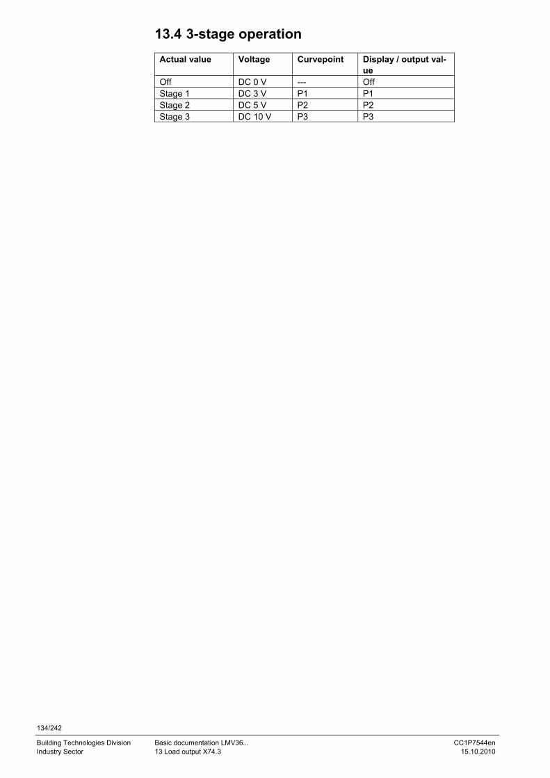
134/242
Building Technologies Division Basic documentation LMV36... CC1P7544en Industry Sector 13 Load output X74.3 15.10.2010
13.4 3-stage operation
Actual value Voltage Curvepoint Display / output val-ue
Off DC 0 V --- Off Stage 1 DC 3 V P1 P1 Stage 2 DC 5 V P2 P2 Stage 3 DC 10 V P3 P3
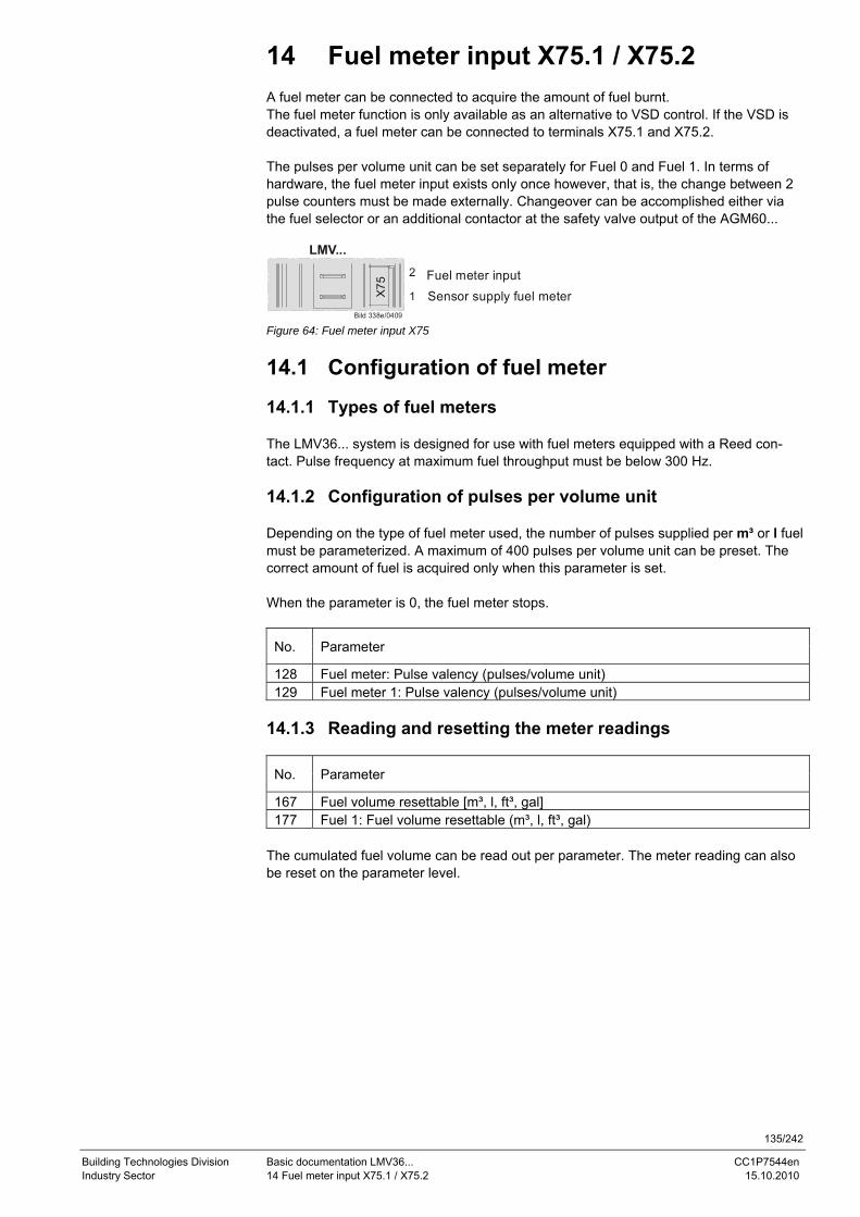
135/242
Building Technologies Division Basic documentation LMV36... CC1P7544en Industry Sector 14 Fuel meter input X75.1 / X75.2 15.10.2010
14 Fuel meter input X75.1 / X75.2 A fuel meter can be connected to acquire the amount of fuel burnt. The fuel meter function is only available as an alternative to VSD control. If the VSD is deactivated, a fuel meter can be connected to terminals X75.1 and X75.2. The pulses per volume unit can be set separately for Fuel 0 and Fuel 1. In terms of hardware, the fuel meter input exists only once however, that is, the change between 2 pulse counters must be made externally. Changeover can be accomplished either via the fuel selector or an additional contactor at the safety valve output of the AGM60...
LMV...
Bild 338e/0409
X75
Sensor supply fuel meterFuel meter input2
1
Figure 64: Fuel meter input X75
14.1 Configuration of fuel meter 14.1.1 Types of fuel meters The LMV36... system is designed for use with fuel meters equipped with a Reed con-tact. Pulse frequency at maximum fuel throughput must be below 300 Hz. 14.1.2 Configuration of pulses per volume unit Depending on the type of fuel meter used, the number of pulses supplied per m³ or l fuel must be parameterized. A maximum of 400 pulses per volume unit can be preset. The correct amount of fuel is acquired only when this parameter is set. When the parameter is 0, the fuel meter stops.
No. Parameter
128 Fuel meter: Pulse valency (pulses/volume unit) 129 Fuel meter 1: Pulse valency (pulses/volume unit)
14.1.3 Reading and resetting the meter readings
No. Parameter
167 Fuel volume resettable [m³, l, ft³, gal] 177 Fuel 1: Fuel volume resettable (m³, l, ft³, gal)
The cumulated fuel volume can be read out per parameter. The meter reading can also be reset on the parameter level.
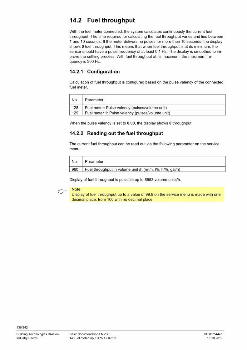
136/242
Building Technologies Division Basic documentation LMV36... CC1P7544en Industry Sector 14 Fuel meter input X75.1 / X75.2 15.10.2010
14.2 Fuel throughput With the fuel meter connected, the system calculates continuously the current fuel throughput. The time required for calculating the fuel throughput varies and lies between 1 and 10 seconds. If the meter delivers no pulses for more than 10 seconds, the display shows 0 fuel throughput. This means that when fuel throughput is at its minimum, the sensor should have a pulse frequency of at least 0.1 Hz. The display is smoothed to im-prove the settling process. With fuel throughput at its maximum, the maximum fre-quency is 300 Hz. 14.2.1 Configuration Calculation of fuel throughput is configured based on the pulse valency of the connected fuel meter.
No. Parameter
128 Fuel meter: Pulse valency (pulses/volume unit) 129 Fuel meter 1: Pulse valency (pulses/volume unit)
When the pulse valency is set to 0.00, the display shows 0 throughput. 14.2.2 Reading out the fuel throughput The current fuel throughput can be read out via the following parameter on the service menu:
No. Parameter
960 Fuel throughput in volume unit /h (m³/h, l/h, ft³/h, gal/h) Display of fuel throughput is possible up to 6553 volume units/h.
Note Display of fuel throughput up to a value of 99.9 on the service menu is made with one decimal place, from 100 with no decimal place.
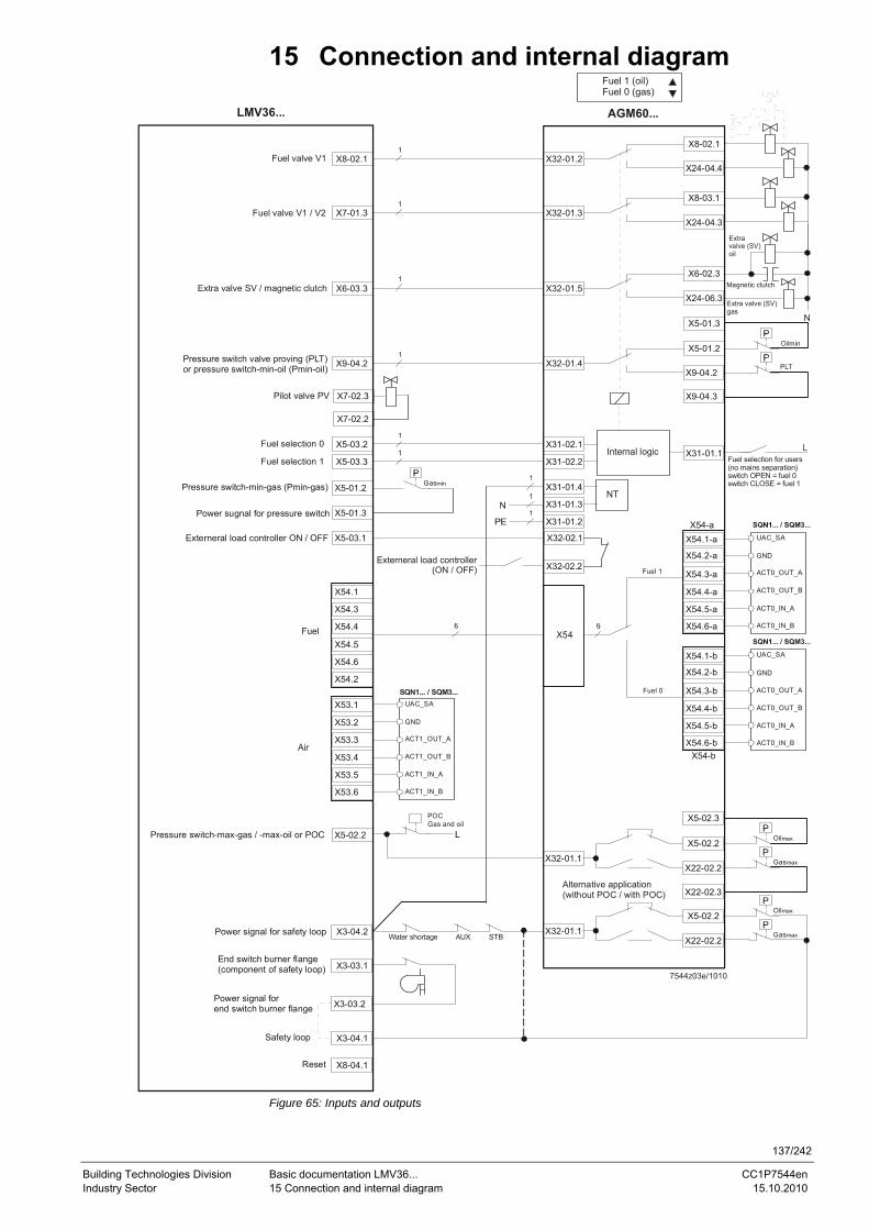
137/242
Building Technologies Division Basic documentation LMV36... CC1P7544en Industry Sector 15 Connection and internal diagram 15.10.2010
15 Connection and internal diagram
X8-02.1 X32-01.2
X8-02.1
X24-04.4
X7-01.3 X32-01.3
X8-03.1
X24-04.3
X6-03.3 X32-01.5
X6-02.3
X24-06.3
X9-04.2Pressure switch valve proving (PLT)or pressure switch-min-oil (Pmin-oil) X32-01.4
X5-01.2
X9-04.2
N
X7-02.3Pilot valve PV
X5-03.2 X31-02.1
X5-03.3 X31-02.2
X31-01.4
X31-01.3
X31-01.2
N
X31-01.1
X54.1
X54.3
X54.4
X54.5
X54.6
X54.2
X54-a
X54-b
Fuel 1
Fuel 0
UAC_SA
ACT0_OUT_A
ACT0_OUT_B
ACT0_IN_A
ACT0_IN_B
GND
UAC_SA
ACT0_OUT_A
ACT0_OUT_B
ACT0_IN_A
ACT0_IN_B
GND
UAC_SA
ACT1_OUT_A
ACT1_OUT_B
ACT1_IN_A
ACT1_IN_B
GND
X53.1
X53.2
X53.3
X53.4
X53.5
X53.6
X5-03.1
X5-01.2
Externeral load controller ON / OFF
Pressure switch-min-gas (Pmin-gas)
X5-02.2
POCGas and oil
Pressure switch-max-gas / -max-oil or POC
X3-03.1
X3-03.2
End switch burner flange(component of safety loop)
Power signal forend switch burner flange
X3-04.1Safety loop
X3-04.2Power signal for safety loop
Gasmin
X32-01.1
X5-02.2
X22-02.2
Oilmax
Gasmax
X32-01.1
X5-02.2
X22-02.2
Oilmax
Gasmax
X8-04.1Reset
X32-02.1
X32-02.2Externeral load controller
(ON / OFF)
X7-02.2
X5-01.3Power sugnal for pressure switch
X5-02.3
Alternative application(without POC / with POC) X22-02.3
X5-01.3
X9-04.3
Fuel 1 (oil)Fuel 0 (gas)
AGM60...LMV36...
Extravalve (SV)oil
Magnetic clutch
Extra valve (SV)gas
Oilmin
PLT
Fuel selection for users(no mains separation)switch OPEN = fuel 0switch CLOSE = fuel 1
Internal logic
NT
7544z03e/1010
X54
SQN1... / SQM3...
Water shortage AUX STB
Fuel valve V1
Fuel valve V1 / V2
Extra valve SV / magnetic clutch
Fuel selection 0
Fuel selection 1
Fuel
Air
X54.1-a
X54.2-a
X54.3-a
X54.4-a
X54.5-a
X54.6-a
X54.1-b
X54.2-b
X54.3-b
X54.4-b
X54.5-b
X54.6-b
Figure 65: Inputs and outputs

138/242
Building Technologies Division Basic documentation LMV36... CC1P7544en Industry Sector 15 Connection and internal diagram 15.10.2010
Shielding: For shielding the cables on the VSD, refer to: • Siemens SED2 VSD Commissioning Manual (G5192), chapters 4 and 7, or • Danfoss Operation Manual VLT 6000 (MG60A703), chapter Installation
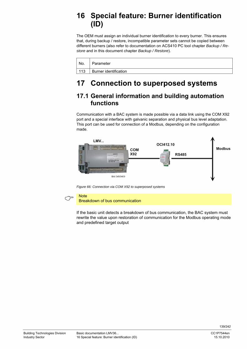
139/242
Building Technologies Division Basic documentation LMV36... CC1P7544en Industry Sector 16 Special feature: Burner identification (ID) 15.10.2010
16 Special feature: Burner identification (ID)
The OEM must assign an individual burner identification to every burner. This ensures that, during backup / restore, incompatible parameter sets cannot be copied between different burners (also refer to documentation on ACS410 PC tool chapter Backup / Re-store and in this document chapter Backup / Restore).
No. Parameter
113 Burner identification
17 Connection to superposed systems
17.1 General information and building automation functions
Communication with a BAC system is made possible via a data link using the COM X92 port and a special interface with galvanic separation and physical bus level adaptation. This port can be used for connection of a Modbus, depending on the configuration made.
OCI412.10
RS485Modbus
LMV...
COM X92
Figure 66: Connection via COM X92 to superposed systems
Note Breakdown of bus communication
If the basic unit detects a breakdown of bus communication, the BAC system must rewrite the value upon restoration of communication for the Modbus operating mode and predefined target output
140/242
Building Technologies Division Basic documentation LMV36... CC1P7544en Industry Sector 17 Connection to superposed systems 15.10.2010
Note Fuel changeover on the basic unit.
After a change of fuel, the BAC system must rewrite the predefined target output. A change of fuel can be detected by cyclic sampling of the type of fuel currently burnt. General setting values for connection of the basic unit to building automation (for factory settings, refer to the Parameter list): Bus communication may only be interrupted for the time set. If communication is disturbed for a longer period of time, the LMV36... basic unit delivers a fault status message and the values set in the basic unit by building automation are reset.
No. Parameter
141
Operating mode BACS 0 = off 1 = Modbus 2 = reserved
142 Setback time in the event of communication breakdown Setting value: 0 = inactive 1…7200 s
148 Default output if communication with building automation is interrupted Setting values: For modulating operation the setting range is as follows: 0…19.9 = burner OFF 20…100 = 20…100% burner rating For multistage operation, the following settings apply: 0 = burner OFF, P1, P2, P3 Invalid = no default output from building automation Default setting: Invalid
149 Fuel 1: Default output if communication with building automation is inter-rupted Setting values: For modulating operation the setting range is as follows: 0…19.9 = burner OFF 20…100 = 20…100% burner rating For multistage operation, the following settings apply: 0 = burner OFF, P1, P2, P3 Invalid = no default output from building automation Default setting: Invalid
The factory settings of the parameters are shown on the Parameter list.
Note For a detailed description of parameters 148 and 149, refer to chapter Default output via building automation.
141/242
Building Technologies Division Basic documentation LMV36... CC1P7544en Industry Sector 17 Connection to superposed systems 15.10.2010
17.2 Modbus With this type of bus protocol, the LMV36... basic unit operates as a slave on the Mod-bus and the transmission mode used is RTU (Remote Terminal Unit). For more detailed information, refer to the Modbus User Documentation (A7541).
No. Parameter
145
Device address for Modbus of basic unit Setting value: 1…247
146
Baud rate for Modbus Setting value: 0 = 9600 1 = 19200
147
Setting of parity for Modbus communication Setting value 0 = none 1 = odd 2 = even
The factory settings of the parameters are shown on the parameter list. Note If bus communication breaks down, the mode, Modbus operating mode and pre-defined target output must be rewritten.
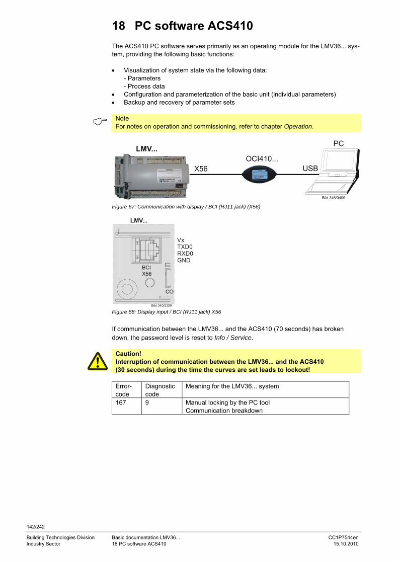
142/242
Building Technologies Division Basic documentation LMV36... CC1P7544en Industry Sector 18 PC software ACS410 15.10.2010
18 PC software ACS410 The ACS410 PC software serves primarily as an operating module for the LMV36... sys-tem, providing the following basic functions: • Visualization of system state via the following data:
- Parameters - Process data
• Configuration and parameterization of the basic unit (individual parameters) • Backup and recovery of parameter sets
Note For notes on operation and commissioning, refer to chapter Operation.
Bild 346/0409
Figure 67: Communication with display / BCI (RJ11 jack) (X56)
LMV...
Bild 340/0309
BCIX56
CO
VxTXD0RXD0GND
Figure 68: Display input / BCI (RJ11 jack) X56 If communication between the LMV36... and the ACS410 (70 seconds) has broken down, the password level is reset to Info / Service.
Caution! Interruption of communication between the LMV36... and the ACS410 (30 seconds) during the time the curves are set leads to lockout!
Error-code
Diagnostic code
Meaning for the LMV36... system
167 9 Manual locking by the PC tool Communication breakdown
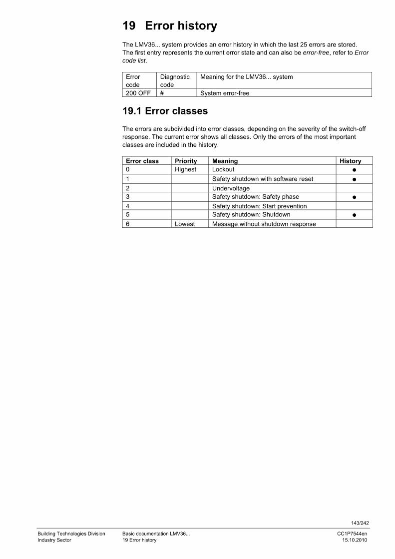
143/242
Building Technologies Division Basic documentation LMV36... CC1P7544en Industry Sector 19 Error history 15.10.2010
19 Error history The LMV36... system provides an error history in which the last 25 errors are stored. The first entry represents the current error state and can also be error-free, refer to Error code list.
Error code
Diagnostic code
Meaning for the LMV36... system
200 OFF # System error-free
19.1 Error classes The errors are subdivided into error classes, depending on the severity of the switch-off response. The current error shows all classes. Only the errors of the most important classes are included in the history.
Error class Priority Meaning History 0 Highest Lockout ● 1 Safety shutdown with software reset ● 2 Undervoltage 3 Safety shutdown: Safety phase ● 4 Safety shutdown: Start prevention 5 Safety shutdown: Shutdown ● 6 Lowest Message without shutdown response
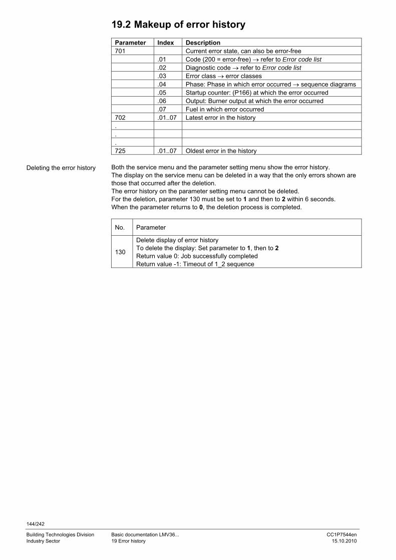
144/242
Building Technologies Division Basic documentation LMV36... CC1P7544en Industry Sector 19 Error history 15.10.2010
19.2 Makeup of error history
Parameter Index Description 701 Current error state, can also be error-free .01 Code (200 = error-free) → refer to Error code list .02 Diagnostic code → refer to Error code list .03 Error class → error classes .04 Phase: Phase in which error occurred → sequence diagrams .05 Startup counter: (P166) at which the error occurred .06 Output: Burner output at which the error occurred .07 Fuel in which error occurred 702 .01..07 Latest error in the history . . . 725 .01..07 Oldest error in the history
Both the service menu and the parameter setting menu show the error history. The display on the service menu can be deleted in a way that the only errors shown are those that occurred after the deletion. The error history on the parameter setting menu cannot be deleted. For the deletion, parameter 130 must be set to 1 and then to 2 within 6 seconds. When the parameter returns to 0, the deletion process is completed.
No. Parameter
130
Delete display of error history To delete the display: Set parameter to 1, then to 2 Return value 0: Job successfully completed Return value -1: Timeout of 1_2 sequence
Deleting the error history
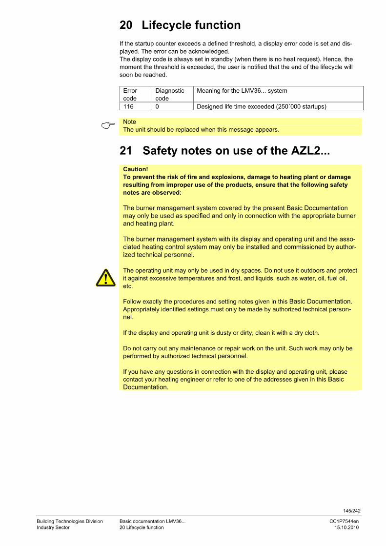
145/242
Building Technologies Division Basic documentation LMV36... CC1P7544en Industry Sector 20 Lifecycle function 15.10.2010
20 Lifecycle function If the startup counter exceeds a defined threshold, a display error code is set and dis-played. The error can be acknowledged. The display code is always set in standby (when there is no heat request). Hence, the moment the threshold is exceeded, the user is notified that the end of the lifecycle will soon be reached.
Error code
Diagnostic code
Meaning for the LMV36... system
116 0 Designed life time exceeded (250´000 startups)
Note The unit should be replaced when this message appears.
21 Safety notes on use of the AZL2...
Caution! To prevent the risk of fire and explosions, damage to heating plant or damage resulting from improper use of the products, ensure that the following safety notes are observed: The burner management system covered by the present Basic Documentation may only be used as specified and only in connection with the appropriate burner and heating plant. The burner management system with its display and operating unit and the asso-ciated heating control system may only be installed and commissioned by author-ized technical personnel. The operating unit may only be used in dry spaces. Do not use it outdoors and protect it against excessive temperatures and frost, and liquids, such as water, oil, fuel oil, etc. Follow exactly the procedures and setting notes given in this Basic Documentation. Appropriately identified settings must only be made by authorized technical person-nel. If the display and operating unit is dusty or dirty, clean it with a dry cloth. Do not carry out any maintenance or repair work on the unit. Such work may only be performed by authorized technical personnel. If you have any questions in connection with the display and operating unit, please contact your heating engineer or refer to one of the addresses given in this Basic Documentation.
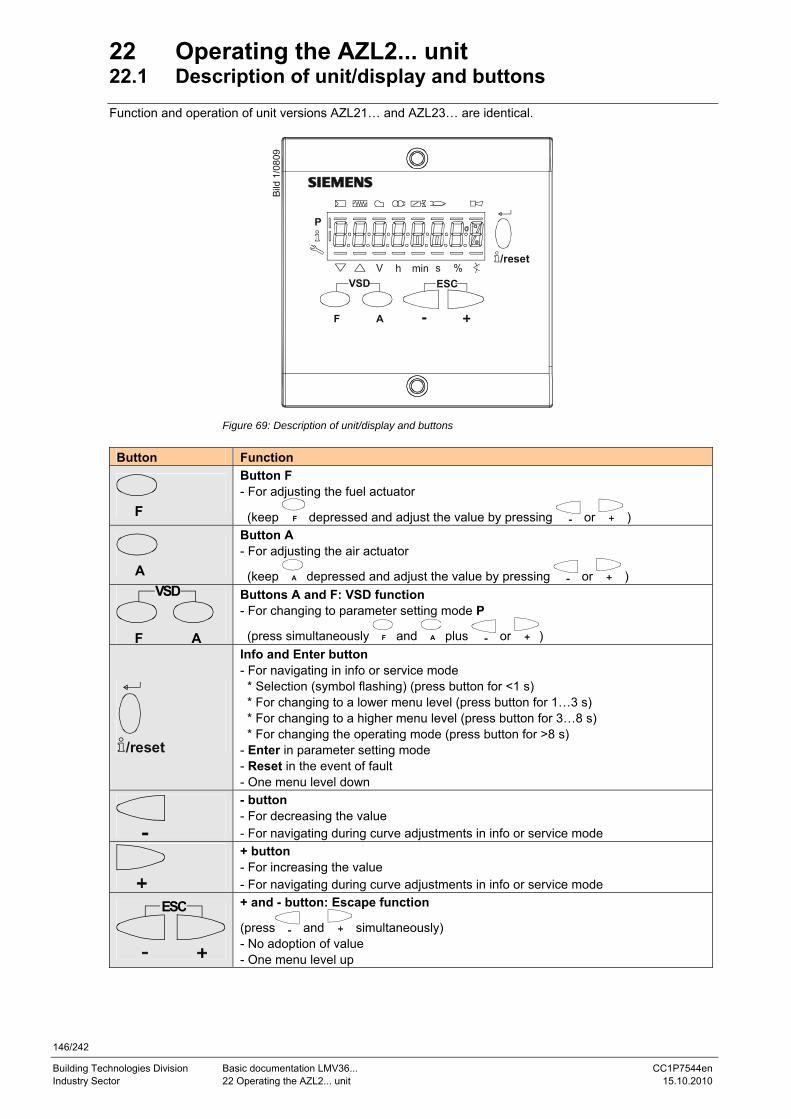
146/242
Building Technologies Division Basic documentation LMV36... CC1P7544en Industry Sector 22 Operating the AZL2... unit 15.10.2010
22 Operating the AZL2... unit 22.1 Description of unit/display and buttons Function and operation of unit versions AZL21… and AZL23… are identical.
Bild
1/0
809
P
V h min s %VSD ESC
/reset
AF
Figure 69: Description of unit/display and buttons
Button Function
F
Button F - For adjusting the fuel actuator
(keep F depressed and adjust the value by pressing or )
A
Button A - For adjusting the air actuator
(keep A depressed and adjust the value by pressing or ) VSD
AF
Buttons A and F: VSD function - For changing to parameter setting mode P
(press simultaneously F and A plus or )
/reset
Info and Enter button - For navigating in info or service mode * Selection (symbol flashing) (press button for <1 s) * For changing to a lower menu level (press button for 1…3 s) * For changing to a higher menu level (press button for 3…8 s) * For changing the operating mode (press button for >8 s) - Enter in parameter setting mode - Reset in the event of fault - One menu level down
- button - For decreasing the value - For navigating during curve adjustments in info or service mode
+ button - For increasing the value - For navigating during curve adjustments in info or service mode
ESC
+ and - button: Escape function
(press and simultaneously) - No adoption of value - One menu level up
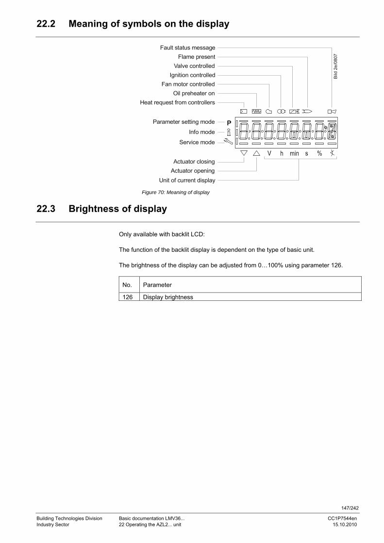
147/242
Building Technologies Division Basic documentation LMV36... CC1P7544en Industry Sector 22 Operating the AZL2... unit 15.10.2010
22.2 Meaning of symbols on the display
Parameter setting mode
Info mode
Service mode
Actuator closingActuator opening
Fan motor controlledOil preheater on
Heat request from controllers
Ignition controlledValve controlled
Flame presentFault status message
Unit of current display
Bild
2e/
0807
Figure 70: Meaning of display
22.3 Brightness of display
Only available with backlit LCD: The function of the backlit display is dependent on the type of basic unit. The brightness of the display can be adjusted from 0…100% using parameter 126.
No. Parameter
126 Display brightness
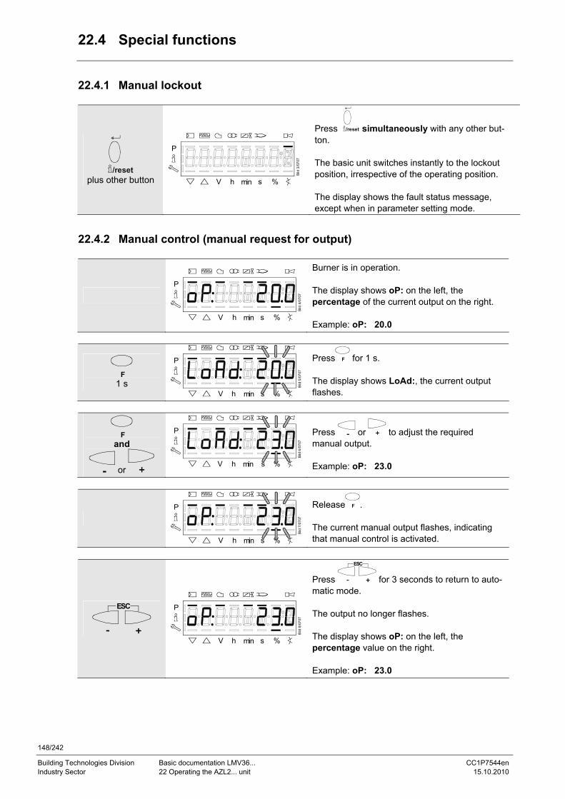
148/242
Building Technologies Division Basic documentation LMV36... CC1P7544en Industry Sector 22 Operating the AZL2... unit 15.10.2010
22.4 Special functions
22.4.1 Manual lockout
/reset plus other button
P
V h min s %
Bild
3/0
707
Press /reset simultaneously with any other but-ton. The basic unit switches instantly to the lockout position, irrespective of the operating position. The display shows the fault status message, except when in parameter setting mode.
22.4.2 Manual control (manual request for output)
P
V h min s %
Bild
4/0
707
Burner is in operation. The display shows oP: on the left, the percentage of the current output on the right. Example: oP: 20.0
F 1 s
P
V h min s %
Bild
5/0
707
Press F for 1 s. The display shows LoAd:, the current output flashes.
F and
or
P
V h min s %
Bild
6/0
707
Press or to adjust the required manual output. Example: oP: 23.0
P
V h min s %
Bild
7/0
707
Release F . The current manual output flashes, indicating that manual control is activated.
ESC
P
V h min s %
Bild
8/0
707
Press
ESC
for 3 seconds to return to auto-matic mode. The output no longer flashes. The display shows oP: on the left, the percentage value on the right. Example: oP: 23.0
149/242
Building Technologies Division Basic documentation LMV36... CC1P7544en Industry Sector 22 Operating the AZL2... unit 15.10.2010
22.5 Timeout for menu operation
The time for automatically leaving the parameter setting level can be adjusted between 10 and 120 minutes, using the following parameter:
No. Parameter
127 Timeout for menu operation If, during that period of time, there is no operation via the AZL2..., the parameter setting level is quit and the password level reset to Info / Service.
Caution! In addition, this timeout or interruption of communication between LMV36... and the AZL2... during the time the curves are set, leads to lockout!
Error- code
Diagnostic code
Meaning for the LMV36... system
167 8 Manual locking by the AZL2... Timeout / communication breakdown
150/242
Building Technologies Division Basic documentation LMV36... CC1P7544en Industry Sector 22 Operating the AZL2... unit 15.10.2010
22.6 Backup / restore
Using the ABE W-FM 50, the settings made on the basic unit can be stored (backup) and then transferred back to the basic unit at a later point in time. Creating a backup data set
No. Parameter
050.0 Index 0: Creation of backup The following parameters can be used to read information about the backup data set:
No. Parameter
055 Burner identification of the ABE W-FM 50 backup data set 056 ASN extraction of the ABE W-FM 50 backup data set 057 Software version used when creating the ABE W-FM 50 backup data set
Restoring a backup data set To transfer a backup data set back to the basic unit, the parameter must be set to 1.
No. Parameter
050.1 Index 1: Execute restore
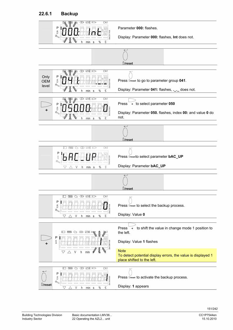
151/242
Building Technologies Division Basic documentation LMV36... CC1P7544en Industry Sector 22 Operating the AZL2... unit 15.10.2010
22.6.1 Backup
Parameter 000: flashes. Display: Parameter 000: flashes, Int does not.
/reset
Only OEM level
Press /reset to go to parameter group 041. Display: Parameter 041: flashes, ._._ does not.
Press to select parameter 050 Display: Parameter 050. flashes, index 00: and value 0 do not.
/reset
7548
z358
/100
9
Press /resetto select parameter bAC_UP Display: Parameter bAC_UP
/reset
Press /reset to select the backup process. Display: Value 0
Press to shift the value in change mode 1 position to the left. Display: Value 1 flashes
Note To detect potential display errors, the value is displayed 1 place shifted to the left.
/reset
Press /reset to activate the backup process. Display: 1 appears

152/242
Building Technologies Division Basic documentation LMV36... CC1P7544en Industry Sector 22 Operating the AZL2... unit 15.10.2010
Approx. 5 s
After about 5 seconds (depending on the duration of the program), 0 appears on the display, indicating the end of the backup process. Display: 0
Note If an error occurs during the backup process, a negative value is displayed. For error diagnos-tics, the cause of the error can be determined from the diagnostic code of error message 137 (see Error code list).
Caution! We recommend to make a backup whenever a parameter is changed!
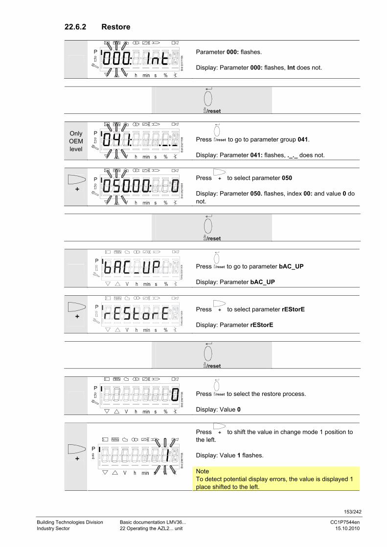
153/242
Building Technologies Division Basic documentation LMV36... CC1P7544en Industry Sector 22 Operating the AZL2... unit 15.10.2010
22.6.2 Restore
Parameter 000: flashes. Display: Parameter 000: flashes, Int does not.
/reset
Only OEM level
Press /reset to go to parameter group 041. Display: Parameter 041: flashes, ._._ does not.
Press to select parameter 050 Display: Parameter 050. flashes, index 00: and value 0 do not.
/reset
7548
z358
/100
9
Press /reset to go to parameter bAC_UP Display: Parameter bAC_UP
7548
z359
/100
9
Press to select parameter rEStorE Display: Parameter rEStorE
/reset
Press /reset to select the restore process. Display: Value 0
Press to shift the value in change mode 1 position to the left. Display: Value 1 flashes.
Note To detect potential display errors, the value is displayed 1 place shifted to the left.
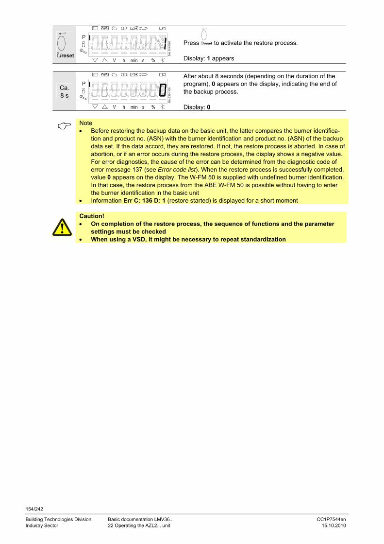
154/242
Building Technologies Division Basic documentation LMV36... CC1P7544en Industry Sector 22 Operating the AZL2... unit 15.10.2010
/reset
Press /reset to activate the restore process. Display: 1 appears
Ca. 8 s
After about 8 seconds (depending on the duration of the program), 0 appears on the display, indicating the end of the backup process. Display: 0
Note • Before restoring the backup data on the basic unit, the latter compares the burner identifica-
tion and product no. (ASN) with the burner identification and product no. (ASN) of the backup data set. If the data accord, they are restored. If not, the restore process is aborted. In case of abortion, or if an error occurs during the restore process, the display shows a negative value. For error diagnostics, the cause of the error can be determined from the diagnostic code of error message 137 (see Error code list). When the restore process is successfully completed, value 0 appears on the display. The W-FM 50 is supplied with undefined burner identification. In that case, the restore process from the ABE W-FM 50 is possible without having to enter the burner identification in the basic unit
• Information Err C: 136 D: 1 (restore started) is displayed for a short moment
Caution! • On completion of the restore process, the sequence of functions and the parameter
settings must be checked • When using a VSD, it might be necessary to repeat standardization
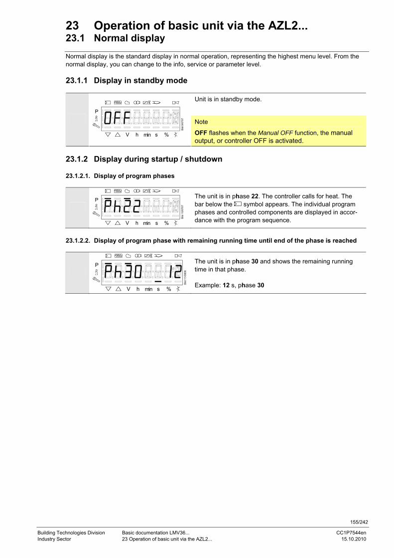
155/242
Building Technologies Division Basic documentation LMV36... CC1P7544en Industry Sector 23 Operation of basic unit via the AZL2... 15.10.2010
23 Operation of basic unit via the AZL2... 23.1 Normal display Normal display is the standard display in normal operation, representing the highest menu level. From the normal display, you can change to the info, service or parameter level. 23.1.1 Display in standby mode
Unit is in standby mode.
P
V h min s %
Bild
9/0
707
Note
OFF flashes when the Manual OFF function, the manual output, or controller OFF is activated.
23.1.2 Display during startup / shutdown 23.1.2.1. Display of program phases
P
V h min s %
Bild
10/
0707
The unit is in phase 22. The controller calls for heat. The bar below the symbol appears. The individual program phases and controlled components are displayed in accor-dance with the program sequence.
23.1.2.2. Display of program phase with remaining running time until end of the phase is reached
P
V h min s %
Bild
11/
0808
The unit is in phase 30 and shows the remaining running time in that phase. Example: 12 s, phase 30
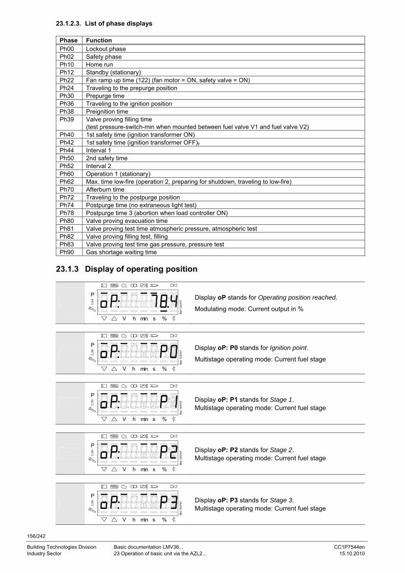
156/242
Building Technologies Division Basic documentation LMV36... CC1P7544en Industry Sector 23 Operation of basic unit via the AZL2... 15.10.2010
23.1.2.3. List of phase displays
Phase Function Ph00 Lockout phase Ph02 Safety phase Ph10 Home run Ph12 Standby (stationary) Ph22 Fan ramp up time (122) (fan motor = ON, safety valve = ON) Ph24 Traveling to the prepurge position Ph30 Prepurge time Ph36 Traveling to the ignition position Ph38 Preignition time Ph39 Valve proving filling time
(test pressure-switch-min when mounted between fuel valve V1 and fuel valve V2) Ph40 1st safety time (ignition transformer ON) Ph42 1st safety time (ignition transformer OFF), Ph44 Interval 1 Ph50 2nd safety time Ph52 Interval 2 Ph60 Operation 1 (stationary) Ph62 Max. time low-fire (operation 2, preparing for shutdown, traveling to low-fire) Ph70 Afterburn time Ph72 Traveling to the postpurge position Ph74 Postpurge time (no extraneous light test) Ph78 Postpurge time 3 (abortion when load controller ON) Ph80 Valve proving evacuation time Ph81 Valve proving test time atmospheric pressure, atmospheric test Ph82 Valve proving filling test, filling Ph83 Valve proving test time gas pressure, pressure test Ph90 Gas shortage waiting time
23.1.3 Display of operating position
P
V h min s %
Bild
12/
0707
Display oP stands for Operating position reached.
Modulating mode: Current output in %
P
V h min s %
Bild
13/
0707
Display oP: P0 stands for Ignition point.
Multistage operating mode: Current fuel stage
P
V h min s %
Bild
14/
0707
Display oP: P1 stands for Stage 1. Multistage operating mode: Current fuel stage
P
V h min s %
Bild
15/
0707
Display oP: P2 stands for Stage 2. Multistage operating mode: Current fuel stage
P
V h min s %
Bild
16/
0707
Display oP: P3 stands for Stage 3. Multistage operating mode: Current fuel stage
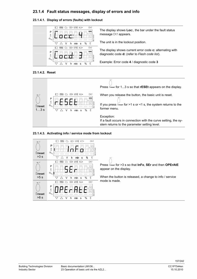
157/242
Building Technologies Division Basic documentation LMV36... CC1P7544en Industry Sector 23 Operation of basic unit via the AZL2... 15.10.2010
23.1.4 Fault status messages, display of errors and info 23.1.4.1. Display of errors (faults) with lockout
P
V h min s %
Bild
17/
0707
P
V h min s %
Bild
18/
0707
The display shows Loc:, the bar under the fault status message appears. The unit is in the lockout position. The display shows current error code c: alternating with diagnostic code d: (refer to Flash code list). Example: Error code 4 / diagnostic code 3
23.1.4.2. Reset
/reset 1…3 s
P
V h min s %
Bild
19/
0707
Press /reset for 1...3 s so that rESEt appears on the display. When you release the button, the basic unit is reset.
If you press /reset for >1 s or <1 s, the system returns to the former menu. Exception: If a fault occurs in connection with the curve setting, the sy-stem returns to the parameter setting level.
23.1.4.3. Activating info / service mode from lockout
/reset >3 s
/reset >5 s
P
V h min s %
Bild
21/
0707
/reset >8 s
P
V h min s %
Bild
22/
0707
Press /reset for >3 s so that InFo, SEr and then OPErAtE appear on the display. When the button is released, a change to info / service mode is made.
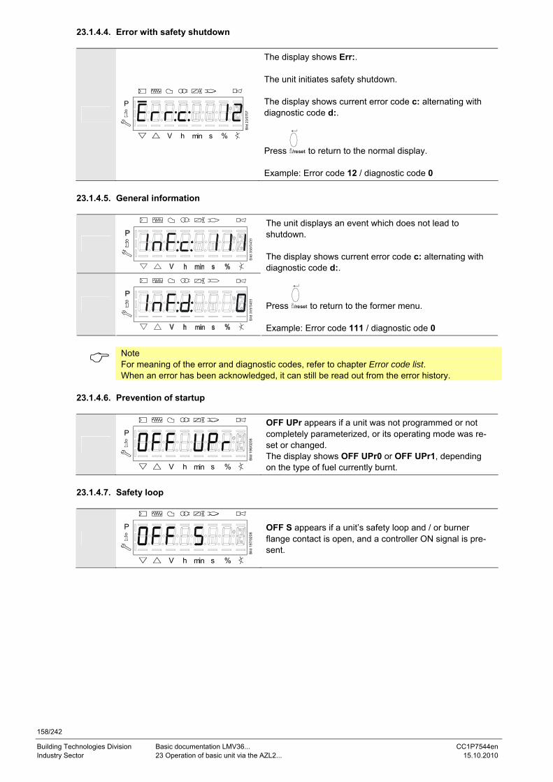
158/242
Building Technologies Division Basic documentation LMV36... CC1P7544en Industry Sector 23 Operation of basic unit via the AZL2... 15.10.2010
23.1.4.4. Error with safety shutdown
P
V h min s %
Bild
23/
0707
The display shows Err:. The unit initiates safety shutdown. The display shows current error code c: alternating with diagnostic code d:.
Press /reset to return to the normal display. Example: Error code 12 / diagnostic code 0
23.1.4.5. General information
The unit displays an event which does not lead to shutdown. The display shows current error code c: alternating with diagnostic code d:.
Press /reset to return to the former menu. Example: Error code 111 / diagnostic ode 0
Note For meaning of the error and diagnostic codes, refer to chapter Error code list. When an error has been acknowledged, it can still be read out from the error history.
23.1.4.6. Prevention of startup
P
V h min s %
Bild
196
/020
8
OFF UPr appears if a unit was not programmed or not completely parameterized, or its operating mode was re-set or changed. The display shows OFF UPr0 or OFF UPr1, depending on the type of fuel currently burnt.
23.1.4.7. Safety loop
P
V h min s %
Bild
197
/020
8
OFF S appears if a unit’s safety loop and / or burner flange contact is open, and a controller ON signal is pre-sent.
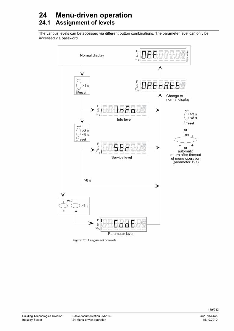
159/242
Building Technologies Division Basic documentation LMV36... CC1P7544en Industry Sector 24 Menu-driven operation 15.10.2010
24 Menu-driven operation 24.1 Assignment of levels The various levels can be accessed via different button combinations. The parameter level can only be accessed via password.
Normal display
>1 s
>1 s
Change tonormal display
>3 s<8 s
>3 s<8 s
or
orautomatic
return after timeoutof menu operation(parameter 127)
Info level
Service level
Parameter level
>8 s
/reset
/reset
/reset
Figure 71: Assignment of levels
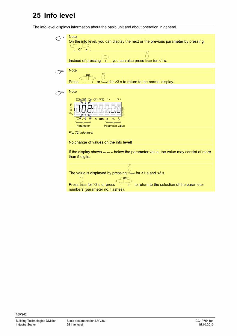
160/242
Building Technologies Division Basic documentation LMV36... CC1P7544en Industry Sector 25 Info level 15.10.2010
25 Info level The info level displays information about the basic unit and about operation in general.
Note On the info level, you can display the next or the previous parameter by pressing
or .
Instead of pressing , you can also press /reset for <1 s.
Note
Press
ESC
or /reset for >3 s to return to the normal display.
Note
P
V h min s %B
ild 2
7e/0
807
Parameter Parameter value Fig. 72: Info level No change of values on the info level! If the display shows below the parameter value, the value may consist of more than 5 digits.
The value is displayed by pressing /reset for >1 s and <3 s.
Press /reset for >3 s or press
ESC
to return to the selection of the parameter numbers (parameter no. flashes).
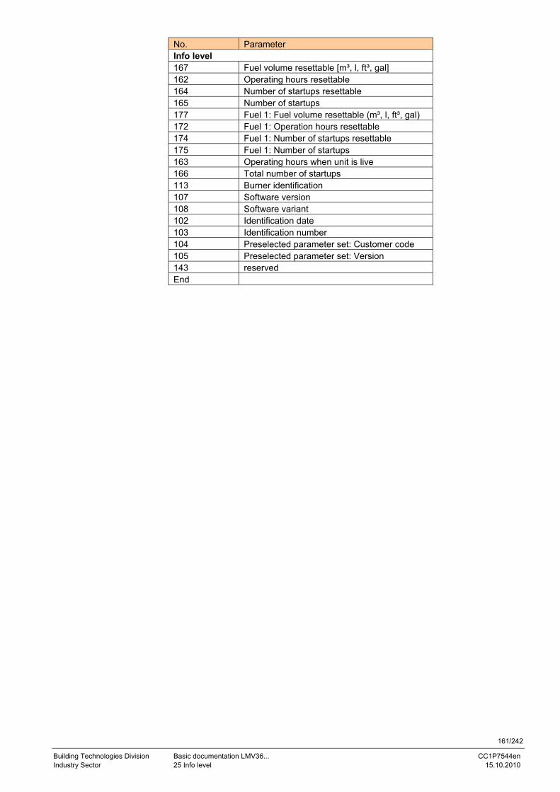
161/242
Building Technologies Division Basic documentation LMV36... CC1P7544en Industry Sector 25 Info level 15.10.2010
No. Parameter Info level 167 Fuel volume resettable [m³, l, ft³, gal] 162 Operating hours resettable 164 Number of startups resettable 165 Number of startups 177 Fuel 1: Fuel volume resettable (m³, l, ft³, gal) 172 Fuel 1: Operation hours resettable 174 Fuel 1: Number of startups resettable 175 Fuel 1: Number of startups 163 Operating hours when unit is live 166 Total number of startups 113 Burner identification 107 Software version 108 Software variant 102 Identification date 103 Identification number 104 Preselected parameter set: Customer code 105 Preselected parameter set: Version 143 reserved End
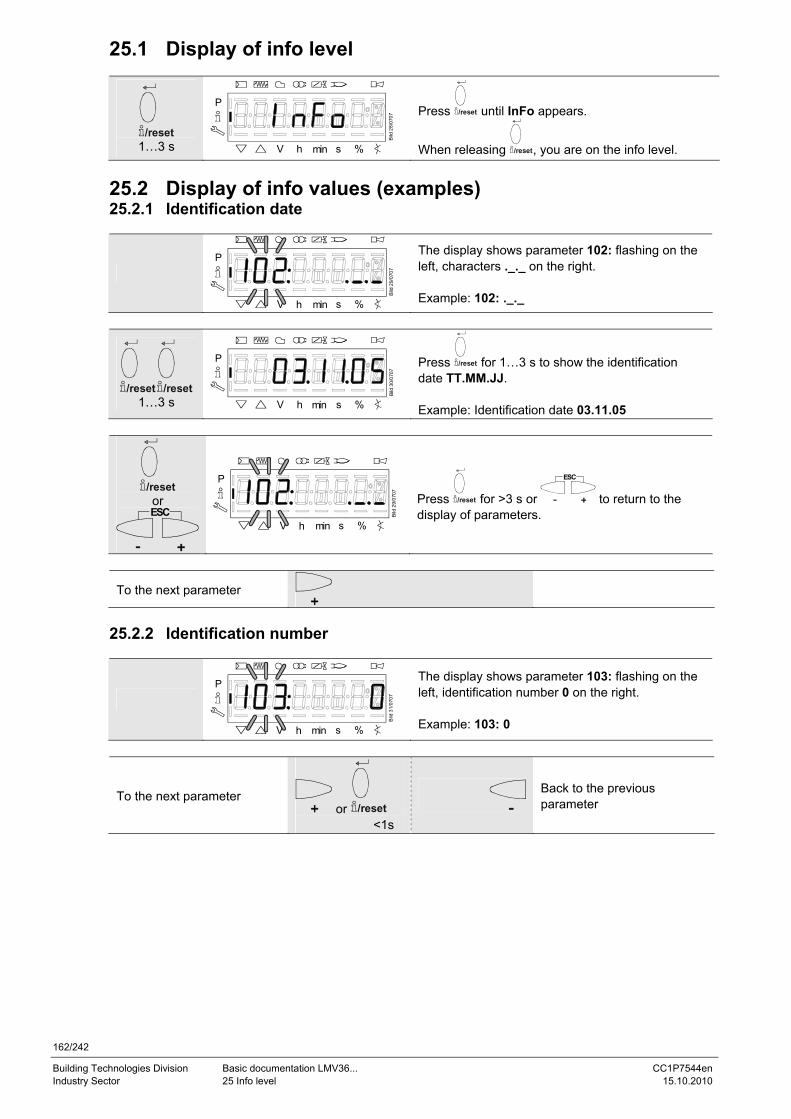
162/242
Building Technologies Division Basic documentation LMV36... CC1P7544en Industry Sector 25 Info level 15.10.2010
25.1 Display of info level
/reset 1…3 s
P
V h min s %
Bild
28/
0707
Press /reset until InFo appears.
When releasing /reset, you are on the info level. 25.2 Display of info values (examples) 25.2.1 Identification date
P
V h min s %
Bild
29/
0707
The display shows parameter 102: flashing on the left, characters ._._ on the right. Example: 102: ._._
/reset /reset 1…3 s
P
V h min s %B
ild 3
0/07
07
Press /reset for 1…3 s to show the identification date TT.MM.JJ. Example: Identification date 03.11.05
/reset or ESC
P
V h min s %
Bild
29/
0707
Press /reset for >3 s or
ESC
to return to the display of parameters.
To the next parameter
25.2.2 Identification number
P
V h min s %
Bild
31/
0707
The display shows parameter 103: flashing on the left, identification number 0 on the right. Example: 103: 0
To the next parameter or /reset
<1s
Back to the previous parameter
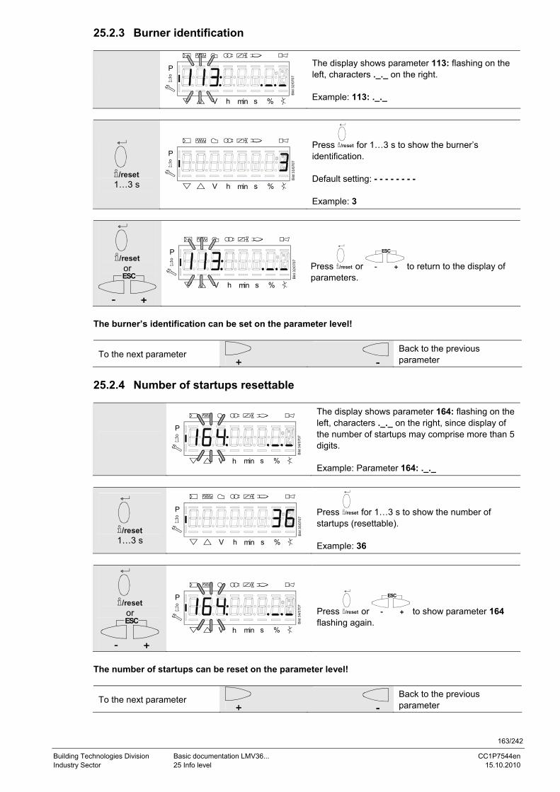
163/242
Building Technologies Division Basic documentation LMV36... CC1P7544en Industry Sector 25 Info level 15.10.2010
25.2.3 Burner identification
P
V h min s %
Bild
32/
0707
The display shows parameter 113: flashing on the left, characters ._._ on the right. Example: 113: ._._
/reset 1…3 s
P
V h min s %
Bild
33/
0707
Press /reset for 1…3 s to show the burner’s identification. Default setting: - - - - - - - - Example: 3
/reset or ESC
P
V h min s %Bi
ld 3
2/07
07
Press /reset or
ESC
to return to the display of parameters.
The burner’s identification can be set on the parameter level!
To the next parameter
Back to the previous parameter
25.2.4 Number of startups resettable
P
V h min s %
Bild
34/
0707
The display shows parameter 164: flashing on the left, characters ._._ on the right, since display of the number of startups may comprise more than 5 digits. Example: Parameter 164: ._._
/reset 1…3 s
P
V h min s %
Bild
35/
0707
Press /reset for 1…3 s to show the number of startups (resettable). Example: 36
/reset or ESC
P
V h min s %
Bild
34/
0707
Press /reset or
ESC
to show parameter 164 flashing again.
The number of startups can be reset on the parameter level!
To the next parameter
Back to the previous parameter
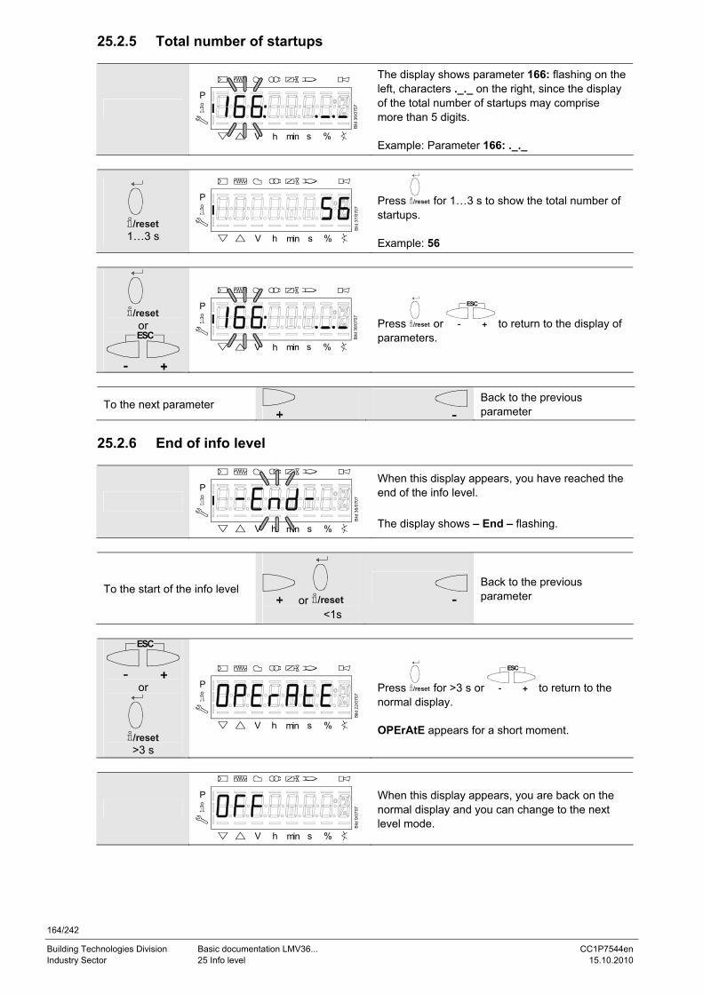
164/242
Building Technologies Division Basic documentation LMV36... CC1P7544en Industry Sector 25 Info level 15.10.2010
25.2.5 Total number of startups
P
V h min s %
Bild
36/
0707
The display shows parameter 166: flashing on the left, characters ._._ on the right, since the display of the total number of startups may comprise more than 5 digits. Example: Parameter 166: ._._
/reset 1…3 s
P
V h min s %
Bild
37/
0707
Press /reset for 1…3 s to show the total number of startups. Example: 56
/reset or ESC
P
V h min s %Bi
ld 3
6/07
07
Press /reset or
ESC
to return to the display of parameters.
To the next parameter
Back to the previous parameter
25.2.6 End of info level
P
V h min s %
Bild
38/
0707
When this display appears, you have reached the end of the info level. The display shows – End – flashing.
To the start of the info level or /reset
<1s Back to the previous parameter
ESC
or
/reset >3 s
P
V h min s %
Bild
22/
0707
Press /reset for >3 s or
ESC
to return to the normal display. OPErAtE appears for a short moment.
P
V h min s %
Bild
9/0
707
When this display appears, you are back on the normal display and you can change to the next level mode.
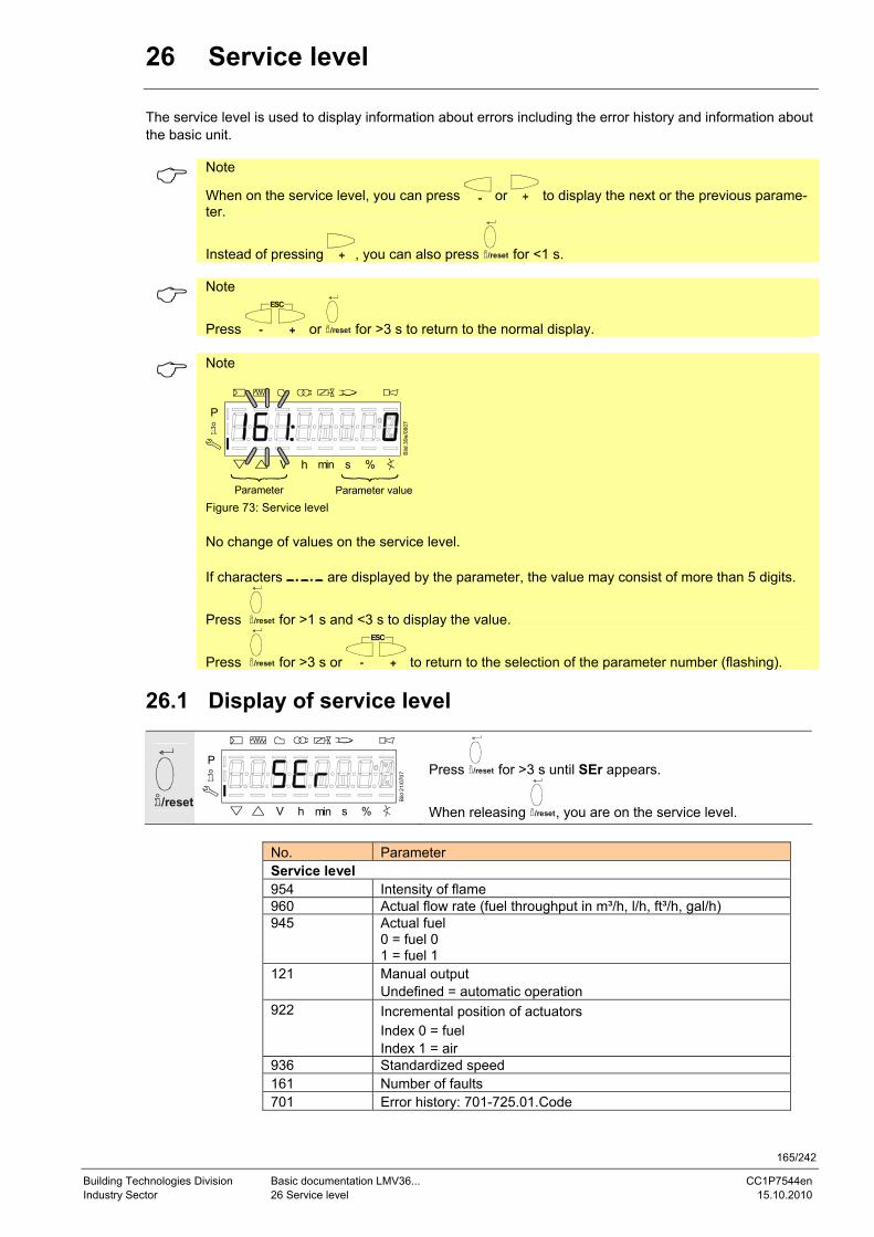
165/242
Building Technologies Division Basic documentation LMV36... CC1P7544en Industry Sector 26 Service level 15.10.2010
26 Service level The service level is used to display information about errors including the error history and information about the basic unit.
Note
When on the service level, you can press or to display the next or the previous parame-ter.
Instead of pressing , you can also press /reset for <1 s.
Note
Press
ESC
or /reset for >3 s to return to the normal display.
Note
P
V h min s %
Bild
39e
/080
7
Parameter Parameter value Figure 73: Service level No change of values on the service level. If characters are displayed by the parameter, the value may consist of more than 5 digits.
Press /reset for >1 s and <3 s to display the value.
Press /reset for >3 s or
ESC
to return to the selection of the parameter number (flashing).
26.1 Display of service level
/reset
P
V h min s %
Bild
21/
0707
Press /reset for >3 s until SEr appears.
When releasing /reset, you are on the service level.
No. Parameter Service level 954 Intensity of flame 960 Actual flow rate (fuel throughput in m³/h, l/h, ft³/h, gal/h) 945 Actual fuel
0 = fuel 0 1 = fuel 1
121 Manual output Undefined = automatic operation
922 Incremental position of actuators Index 0 = fuel Index 1 = air
936 Standardized speed 161 Number of faults 701 Error history: 701-725.01.Code
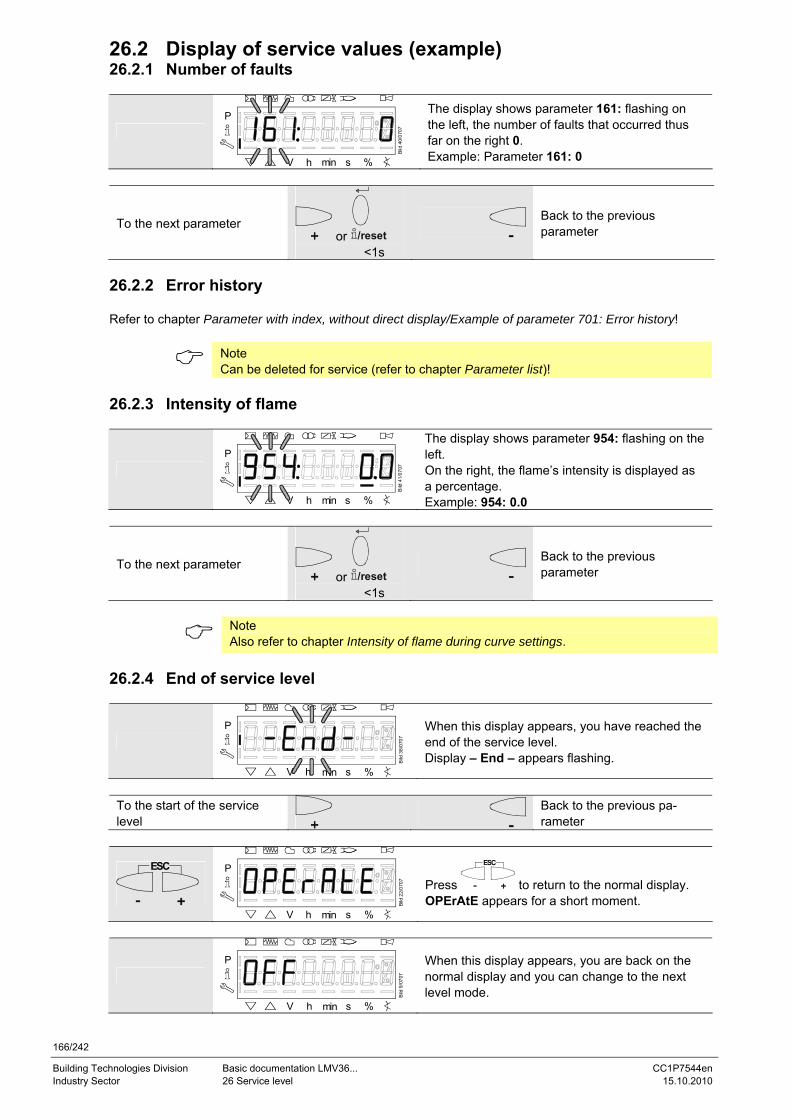
166/242
Building Technologies Division Basic documentation LMV36... CC1P7544en Industry Sector 26 Service level 15.10.2010
26.2 Display of service values (example) 26.2.1 Number of faults
P
V h min s %
Bild
40/
0707
The display shows parameter 161: flashing on the left, the number of faults that occurred thus far on the right 0. Example: Parameter 161: 0
To the next parameter or /reset
<1s
Back to the previous parameter
26.2.2 Error history Refer to chapter Parameter with index, without direct display/Example of parameter 701: Error history!
Note Can be deleted for service (refer to chapter Parameter list)!
26.2.3 Intensity of flame
P
V h min s %
Bild
41/
0707
The display shows parameter 954: flashing on the left. On the right, the flame’s intensity is displayed as a percentage. Example: 954: 0.0
To the next parameter or /reset
<1s Back to the previous parameter
Note Also refer to chapter Intensity of flame during curve settings.
26.2.4 End of service level
P
V h min s %
Bild
38/
0707
When this display appears, you have reached the end of the service level. Display – End – appears flashing.
To the start of the service level Back to the previous pa-
rameter
ESC
P
V h min s %
Bild
22/
0707
Press
ESC
to return to the normal display. OPErAtE appears for a short moment.
P
V h min s %
Bild
9/0
707
When this display appears, you are back on the normal display and you can change to the next level mode.
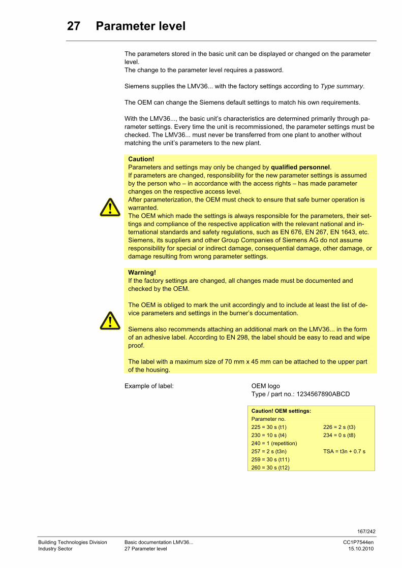
167/242
Building Technologies Division Basic documentation LMV36... CC1P7544en Industry Sector 27 Parameter level 15.10.2010
27 Parameter level
The parameters stored in the basic unit can be displayed or changed on the parameter level. The change to the parameter level requires a password.
Siemens supplies the LMV36... with the factory settings according to Type summary. The OEM can change the Siemens default settings to match his own requirements. With the LMV36..., the basic unit’s characteristics are determined primarily through pa-rameter settings. Every time the unit is recommissioned, the parameter settings must be checked. The LMV36... must never be transferred from one plant to another without matching the unit’s parameters to the new plant.
Caution! Parameters and settings may only be changed by qualified personnel. If parameters are changed, responsibility for the new parameter settings is assumed by the person who – in accordance with the access rights – has made parameter changes on the respective access level. After parameterization, the OEM must check to ensure that safe burner operation is warranted. The OEM which made the settings is always responsible for the parameters, their set-tings and compliance of the respective application with the relevant national and in-ternational standards and safety regulations, such as EN 676, EN 267, EN 1643, etc. Siemens, its suppliers and other Group Companies of Siemens AG do not assume responsibility for special or indirect damage, consequential damage, other damage, or damage resulting from wrong parameter settings.
Warning! If the factory settings are changed, all changes made must be documented and checked by the OEM. The OEM is obliged to mark the unit accordingly and to include at least the list of de-vice parameters and settings in the burner’s documentation. Siemens also recommends attaching an additional mark on the LMV36... in the form of an adhesive label. According to EN 298, the label should be easy to read and wipe proof. The label with a maximum size of 70 mm x 45 mm can be attached to the upper part of the housing.
Example of label: OEM logo
Type / part no.: 1234567890ABCD
Caution! OEM settings: Parameter no. 225 = 30 s (t1) 226 = 2 s (t3) 230 = 10 s (t4) 234 = 0 s (t8) 240 = 1 (repetition) 257 = 2 s (t3n) TSA = t3n + 0.7 s 259 = 30 s (t11) 260 = 30 s (t12)
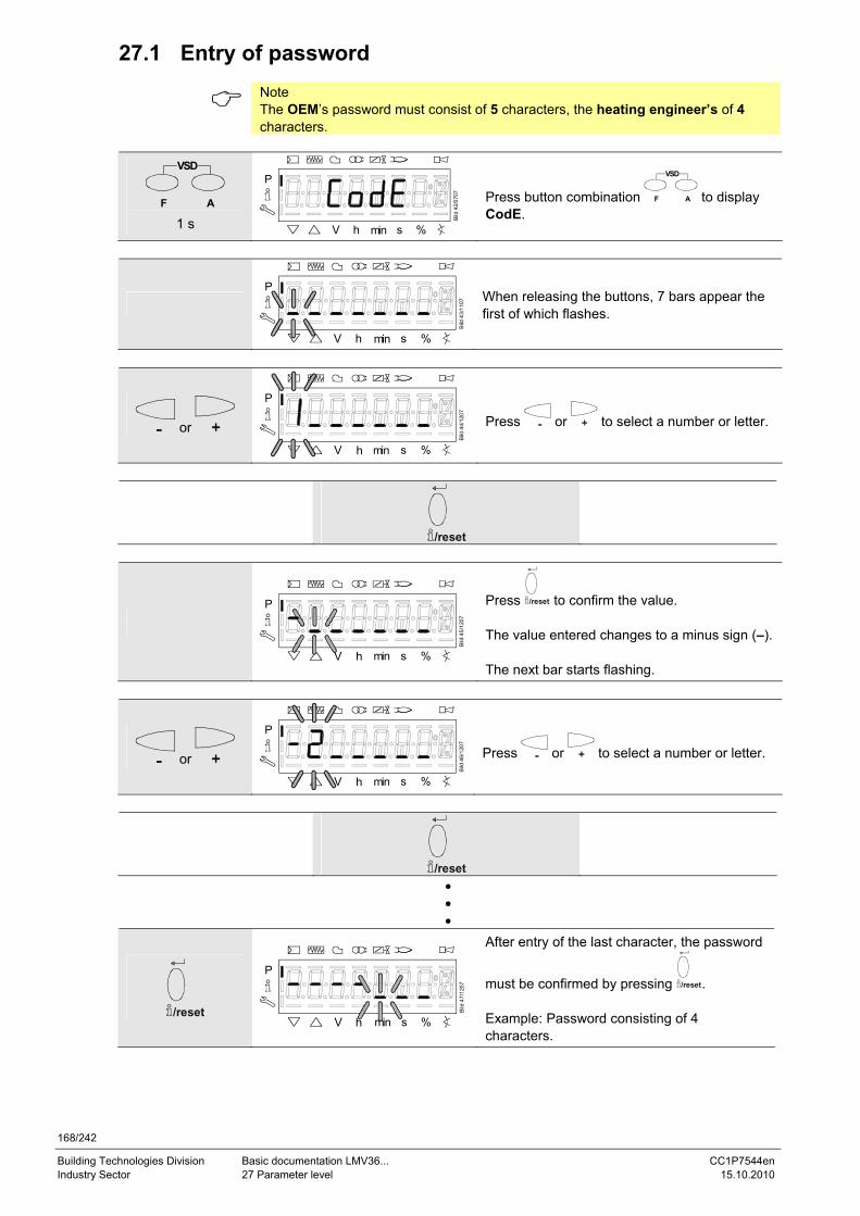
168/242
Building Technologies Division Basic documentation LMV36... CC1P7544en Industry Sector 27 Parameter level 15.10.2010
27.1 Entry of password
Note The OEM’s password must consist of 5 characters, the heating engineer’s of 4 characters.
VSD
AF 1 s
P
V h min s %
Bild
42/
0707
Press button combination
VSD
AF to display CodE.
P
V h min s %
Bild
43/
1107
When releasing the buttons, 7 bars appear the first of which flashes.
or
P
V h min s %Bi
ld 4
4/12
07
Press or to select a number or letter.
/reset
P
V h min s %
Bild
45/
1207
Press /reset to confirm the value. The value entered changes to a minus sign (–). The next bar starts flashing.
or
P
V h min s %
Bild
46/
1207
Press or to select a number or letter.
/reset
• • •
/reset
P
V h min s %
Bild
47/
1207
After entry of the last character, the password
must be confirmed by pressing /reset. Example: Password consisting of 4 characters.
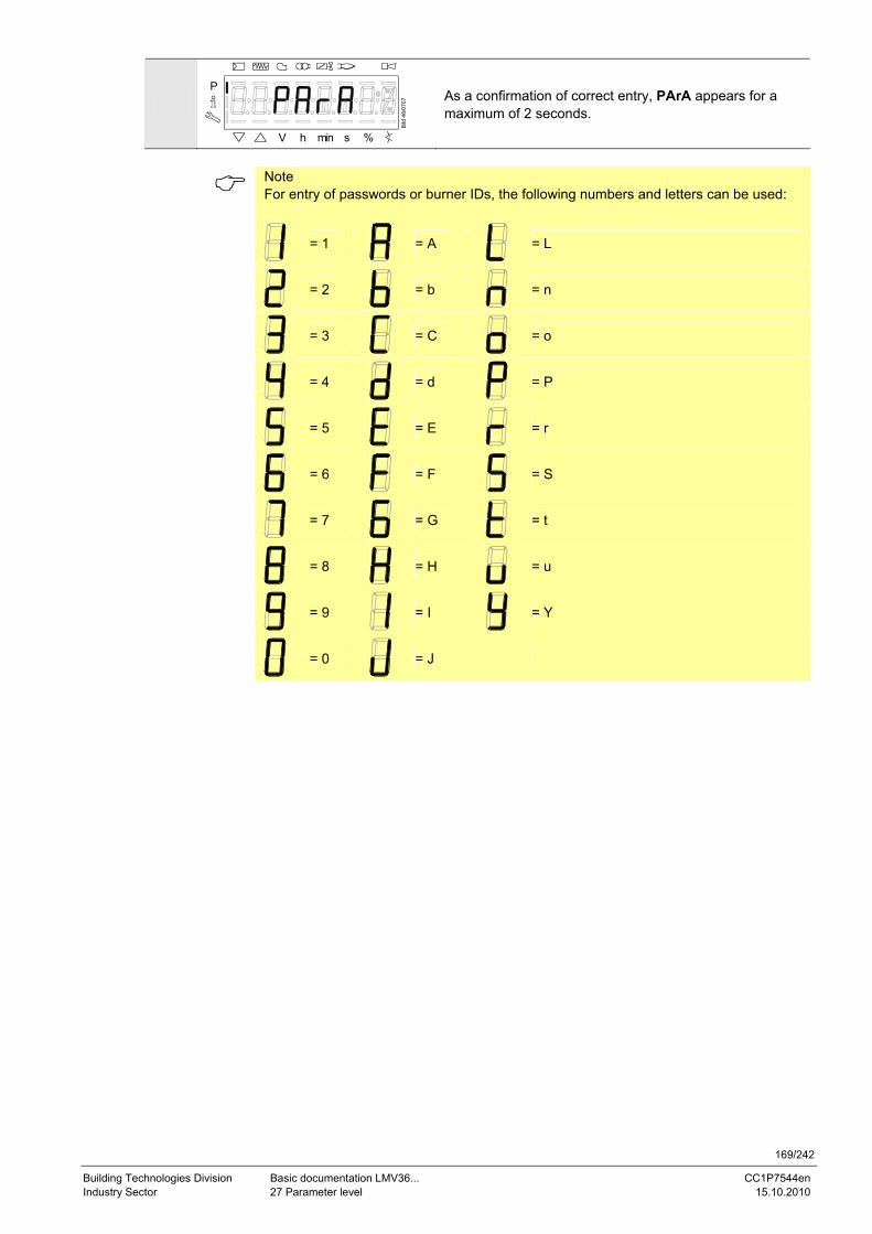
169/242
Building Technologies Division Basic documentation LMV36... CC1P7544en Industry Sector 27 Parameter level 15.10.2010
P
V h min s %
Bild
48/
0707
As a confirmation of correct entry, PArA appears for a maximum of 2 seconds.
Note For entry of passwords or burner IDs, the following numbers and letters can be used:
= 1
= A
= L
= 2
= b
= n
= 3
= C
= o
= 4
= d
= P
= 5
= E
= r
= 6
= F
= S
= 7
= G
= t
= 8
= H
= u
= 9
= I
= Y
= 0
= J
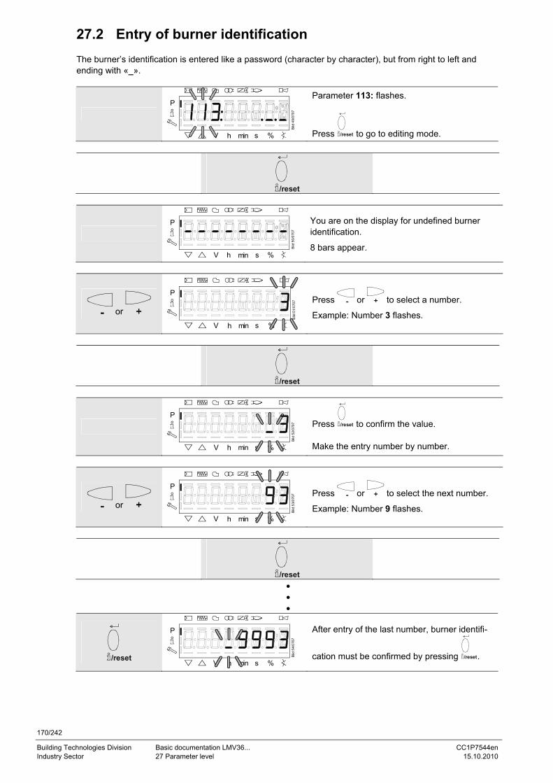
170/242
Building Technologies Division Basic documentation LMV36... CC1P7544en Industry Sector 27 Parameter level 15.10.2010
27.2 Entry of burner identification
The burner’s identification is entered like a password (character by character), but from right to left and ending with «_».
P
V h min s %
Bild
49/
0707
Parameter 113: flashes.
Press /reset to go to editing mode.
/reset
P
V h min s %
Bild
50/
0707
You are on the display for undefined burner identification.
8 bars appear.
or
P
V h min s %
Bild
51/
0707
Press or to select a number.
Example: Number 3 flashes.
/reset
P
V h min s %
Bild
52/
0707
Press /reset to confirm the value. Make the entry number by number.
or
P
V h min s %
Bild
53/
0707
Press or to select the next number.
Example: Number 9 flashes.
/reset
• • •
/reset
P
V h min s %
Bild
54/
0707
After entry of the last number, burner identifi-
cation must be confirmed by pressing /reset.
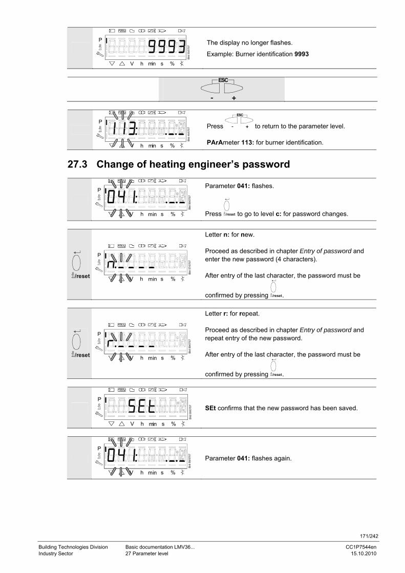
171/242
Building Technologies Division Basic documentation LMV36... CC1P7544en Industry Sector 27 Parameter level 15.10.2010
P
V h min s %
Bild
55/
0707
The display no longer flashes.
Example: Burner identification 9993
ESC
P
V h min s %
Bild
49/
0707
Press
ESC
to return to the parameter level. PArAmeter 113: for burner identification.
27.3 Change of heating engineer’s password
P
V h min s %
Bild
56/
0707
Parameter 041: flashes.
Press /reset to go to level c: for password changes.
/reset
P
V h min s %
Bild
57/
0707
Letter n: for new. Proceed as described in chapter Entry of password and enter the new password (4 characters). After entry of the last character, the password must be
confirmed by pressing /reset.
/reset
P
V h min s %
Bild
58/
0707
Letter r: for repeat. Proceed as described in chapter Entry of password and repeat entry of the new password. After entry of the last character, the password must be
confirmed by pressing /reset.
P
V h min s %
Bild
59/
0707
SEt confirms that the new password has been saved.
P
V h min s %
Bild
56/
0707
Parameter 041: flashes again.
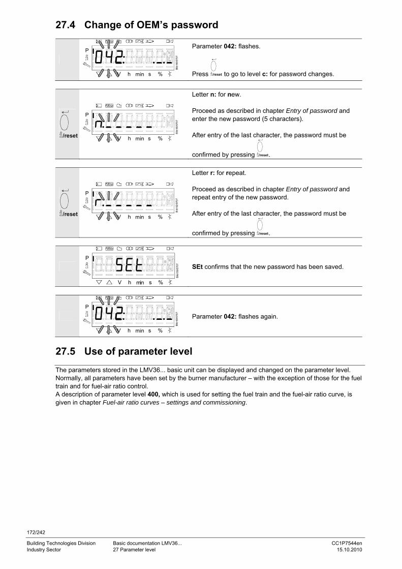
172/242
Building Technologies Division Basic documentation LMV36... CC1P7544en Industry Sector 27 Parameter level 15.10.2010
27.4 Change of OEM’s password
P
V h min s %
Bild
60/
0707
Parameter 042: flashes.
Press /reset to go to level c: for password changes.
/reset
P
V h min s %
Bild
60/
0707
Letter n: for new. Proceed as described in chapter Entry of password and enter the new password (5 characters). After entry of the last character, the password must be
confirmed by pressing /reset.
/reset
P
V h min s %
Bild
62/
0707
Letter r: for repeat. Proceed as described in chapter Entry of password and repeat entry of the new password. After entry of the last character, the password must be
confirmed by pressing /reset.
P
V h min s %
Bild
59/
0707
SEt confirms that the new password has been saved.
P
V h min s %
Bild
60/
0707
Parameter 042: flashes again.
27.5 Use of parameter level The parameters stored in the LMV36... basic unit can be displayed and changed on the parameter level. Normally, all parameters have been set by the burner manufacturer – with the exception of those for the fuel train and for fuel-air ratio control. A description of parameter level 400, which is used for setting the fuel train and the fuel-air ratio curve, is given in chapter Fuel-air ratio curves – settings and commissioning.
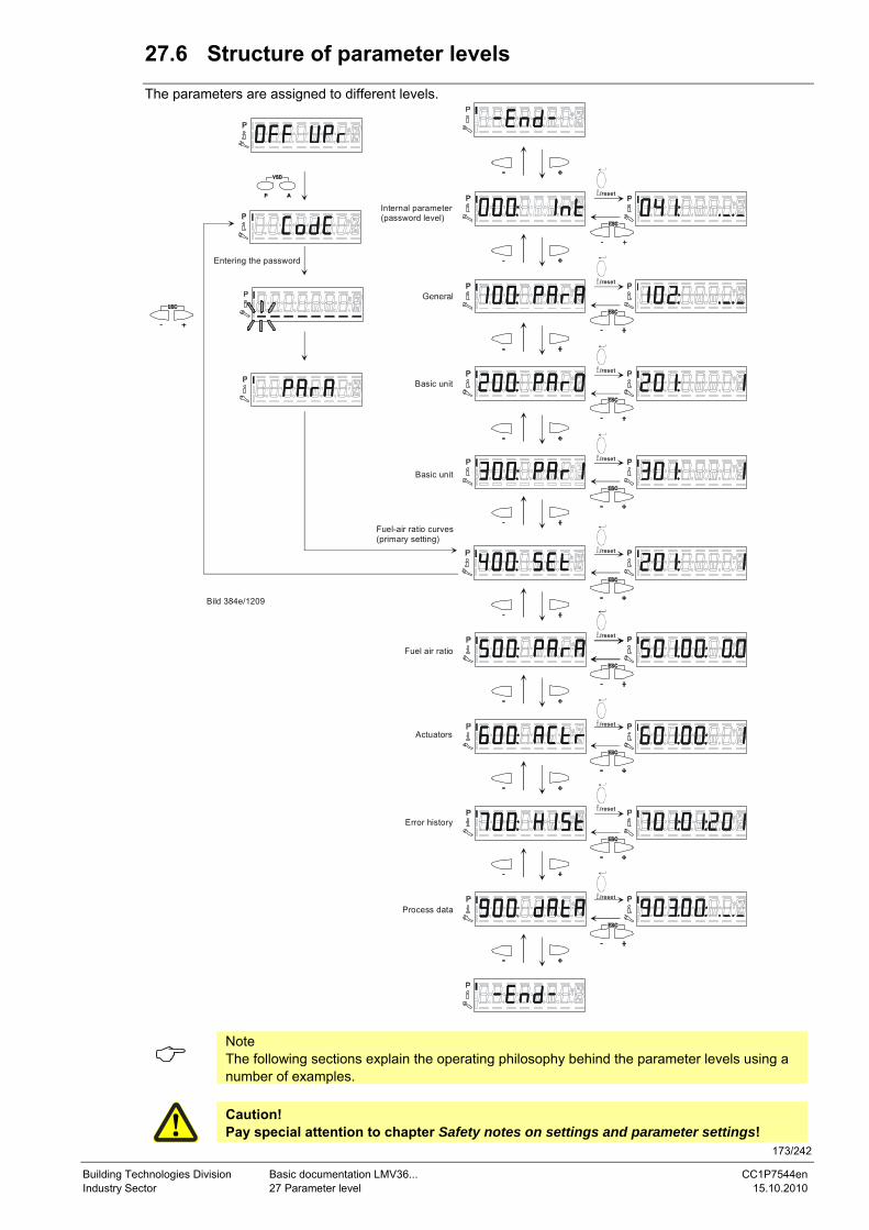
173/242
Building Technologies Division Basic documentation LMV36... CC1P7544en Industry Sector 27 Parameter level 15.10.2010
27.6 Structure of parameter levels The parameters are assigned to different levels.
Fuel-air ratio curves(primary setting)
Entering the password
Basic unit
Internal parameter(password level)
Fuel air ratio
Actuators
Error history
Process data
Bild 384e/1209
Basic unit
/reset
/reset
/reset
/reset
/reset
/reset
/reset
/reset
/reset
Note The following sections explain the operating philosophy behind the parameter levels using a number of examples.
Caution! Pay special attention to chapter Safety notes on settings and parameter settings!
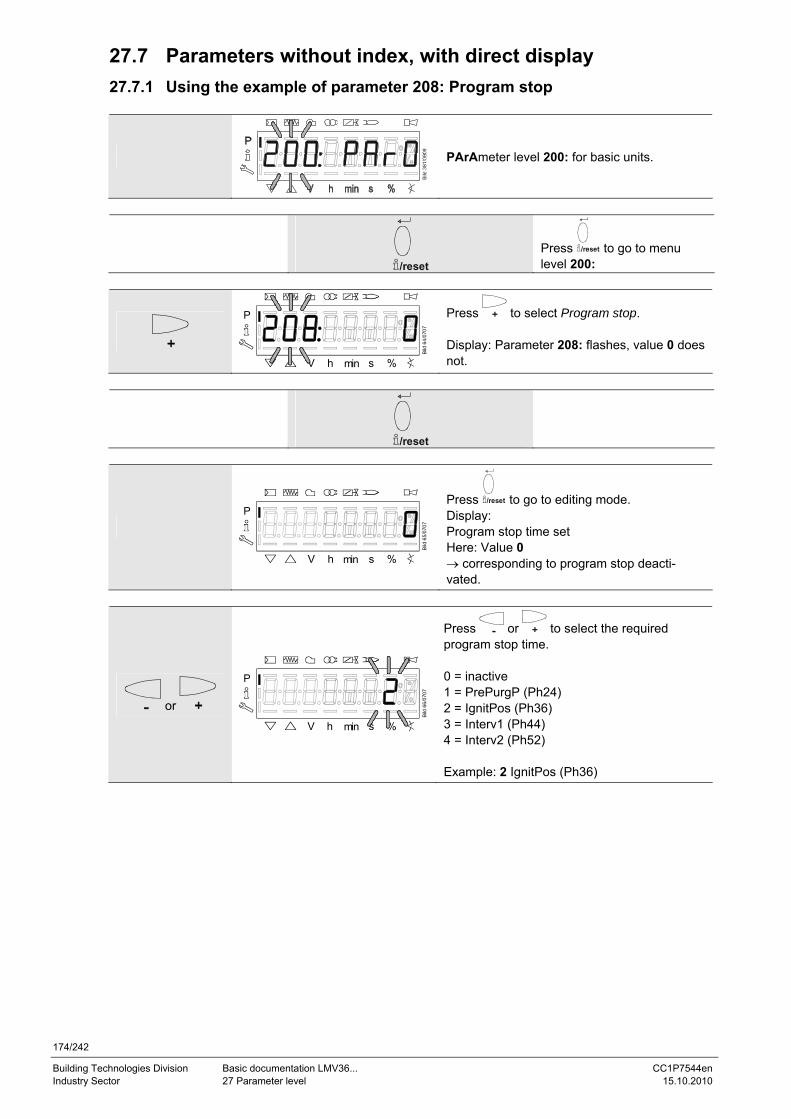
174/242
Building Technologies Division Basic documentation LMV36... CC1P7544en Industry Sector 27 Parameter level 15.10.2010
27.7 Parameters without index, with direct display 27.7.1 Using the example of parameter 208: Program stop
PArAmeter level 200: for basic units.
/reset
Press /reset to go to menu level 200:
P
V h min s %
Bild
64/
0707
Press to select Program stop. Display: Parameter 208: flashes, value 0 does not.
/reset
P
V h min s %
Bild
65/
0707
Press /reset to go to editing mode. Display: Program stop time set Here: Value 0 → corresponding to program stop deacti-vated.
or
P
V h min s %
Bild
66/
0707
Press or to select the required program stop time. 0 = inactive 1 = PrePurgP (Ph24) 2 = IgnitPos (Ph36) 3 = Interv1 (Ph44) 4 = Interv2 (Ph52) Example: 2 IgnitPos (Ph36)
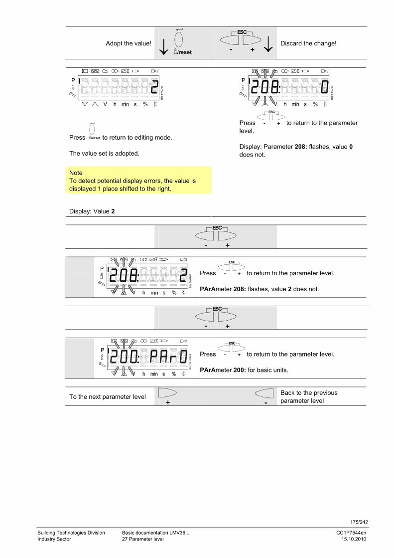
175/242
Building Technologies Division Basic documentation LMV36... CC1P7544en Industry Sector 27 Parameter level 15.10.2010
Adopt the value! ↓ /reset
ESC
↓ Discard the change!
P
V h min s %
Bild
67/
0707
Press /reset to return to editing mode. The value set is adopted.
Note To detect potential display errors, the value is displayed 1 place shifted to the right.
Display: Value 2
P
V h min s %
Bild
68/
0707
Press
ESC
to return to the parameter level. Display: Parameter 208: flashes, value 0 does not.
ESC
P
V h min s %
Bild
69/
0707
Press
ESC
to return to the parameter level. PArAmeter 208: flashes, value 2 does not.
ESC
Press
ESC
to return to the parameter level. PArAmeter 200: for basic units.
To the next parameter level Back to the previous parameter level
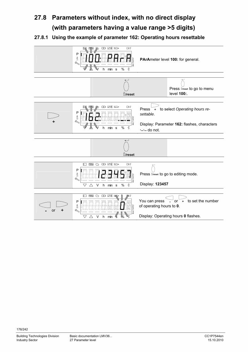
176/242
Building Technologies Division Basic documentation LMV36... CC1P7544en Industry Sector 27 Parameter level 15.10.2010
27.8 Parameters without index, with no direct display (with parameters having a value range >5 digits)
27.8.1 Using the example of parameter 162: Operating hours resettable
P
V h min s %
Bild
70/
0707
PArAmeter level 100: for general.
/reset
Press /reset to go to menu level 100:.
P
V h min s %Bi
ld 7
1/07
07
Press to select Operating hours re-settable. Display: Parameter 162: flashes, characters ._._ do not.
/reset
P
V h min s %
Bild
72/
0707
Press /reset to go to editing mode. Display: 123457
or
P
V h min s %
Biod
73/
0707
You can press or to set the number of operating hours to 0. Display: Operating hours 0 flashes.
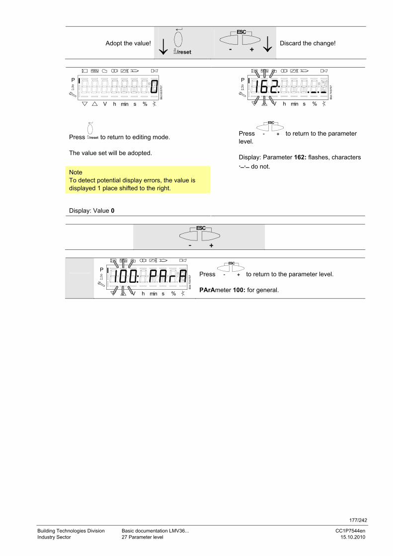
177/242
Building Technologies Division Basic documentation LMV36... CC1P7544en Industry Sector 27 Parameter level 15.10.2010
Adopt the value! ↓ /reset
ESC
↓ Discard the change!
P
V h min s %
Bild
65/
0707
Press /reset to return to editing mode. The value set will be adopted.
Note To detect potential display errors, the value is displayed 1 place shifted to the right.
Display: Value 0
P
V h min s %
Bild
74/
0707
Press
ESC
to return to the parameter level. Display: Parameter 162: flashes, characters ._._ do not.
ESC
P
V h min s %
Bild
70/
0707
Press
ESC
to return to the parameter level. PArAmeter 100: for general.
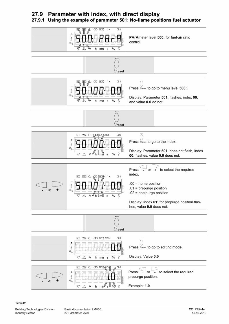
178/242
Building Technologies Division Basic documentation LMV36... CC1P7544en Industry Sector 27 Parameter level 15.10.2010
27.9 Parameter with index, with direct display 27.9.1 Using the example of parameter 501: No-flame positions fuel actuator
P
V h min s %
Bild
75/
0707
PArAmeter level 500: for fuel-air ratio control.
/reset
P
V h min s %
Bild
76/
0707
Press /reset to go to menu level 500:. Display: Parameter 501. flashes, index 00: and value 0.0 do not.
/reset
P
V h min s %
Bild
77/
0707
Press /reset to go to the index. Display: Parameter 501. does not flash, index 00: flashes, value 0.0 does not.
or
P
V h min s %
Bild
78/
0707
Press or to select the required index. .00 = home position .01 = prepurge position .02 = postpurge position Display: Index 01: for prepurge position flas-hes, value 0.0 does not.
/reset
P
V h min s %
Bild
79/
0707
Press /reset to go to editing mode. Display: Value 0.0
or
P
V h min s %
Bild
80/
0707
Press or to select the required prepurge position. Example: 1.0
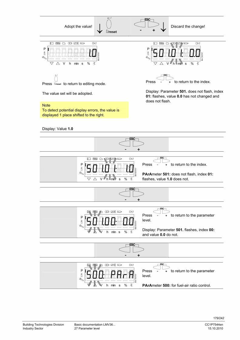
179/242
Building Technologies Division Basic documentation LMV36... CC1P7544en Industry Sector 27 Parameter level 15.10.2010
Adopt the value! ↓ /reset
ESC
↓ Discard the change!
P
V h min s %
Bild
81/
0707
Press /reset to return to editing mode. The value set will be adopted.
Note To detect potential display errors, the value is displayed 1 place shifted to the right.
Display: Value 1.0
P
V h min s %
Bild
78/
0707
Press
ESC
to return to the index. Display: Parameter 501. does not flash, index 01: flashes, value 0.0 has not changed and does not flash.
ESC
P
V h min s %
Bild
82/
0707
Press
ESC
to return to the index. PArAmeter 501: does not flash, index 01: flashes, value 1.0 does not.
ESC
P
V h min s %
Bild
83/
0707
Press
ESC
to return to the parameter level. Display: Parameter 501. flashes, index 00: and value 0.0 do not.
ESC
P
V h min s %
Bild
75/
0707
Press
ESC
to return to the parameter level. PArAmeter 500: for fuel-air ratio control.
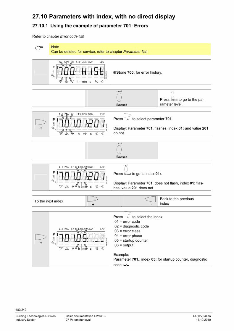
180/242
Building Technologies Division Basic documentation LMV36... CC1P7544en Industry Sector 27 Parameter level 15.10.2010
27.10 Parameters with index, with no direct display 27.10.1 Using the example of parameter 701: Errors Refer to chapter Error code list!
Note Can be deleted for service, refer to chapter Parameter list!
P
V h min s %
Bild
84/
0707
HIStorie 700: for error history.
/reset
Press /reset to go to the pa-rameter level.
P
V h min s %
Bild
85/
0707
Press to select parameter 701. Display: Parameter 701. flashes, index 01: and value 201 do not.
/reset
P
V h min s %
Bild
86/
0707
Press /reset to go to index 01:. Display: Parameter 701. does not flash, index 01: flas-hes, value 201 does not.
To the next index
Back to the previous index
P
V h min s %
Bild
87/
0707
Press to select the index: .01 = error code .02 = diagnostic code .03 = error class .04 = error phase .05 = startup counter .06 = output Example: Parameter 701., index 05: for startup counter, diagnostic code ._._
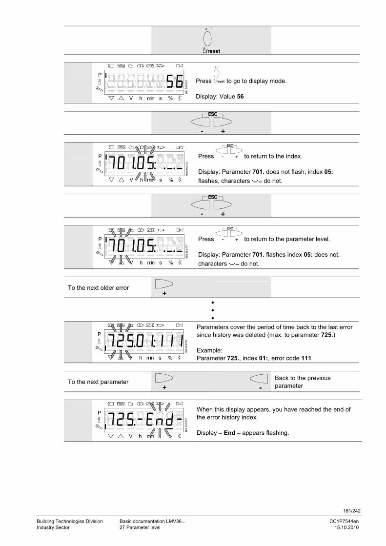
181/242
Building Technologies Division Basic documentation LMV36... CC1P7544en Industry Sector 27 Parameter level 15.10.2010
/reset
P
V h min s %
Bild
88/
0707
Press /reset to go to display mode. Display: Value 56
ESC
P
V h min s %Bi
ld 8
7/07
07
Press
ESC
to return to the index. Display: Parameter 701. does not flash, index 05: flashes, characters ._._ do not.
ESC
P
V h min s %
Bild
89/
0707
Press
ESC
to return to the parameter level. Display: Parameter 701. flashes index 05: does not, characters ._._ do not.
To the next older error
• • •
P
V h min s %
Bild
90/
0707
Parameters cover the period of time back to the last error since history was deleted (max. to parameter 725.) Example: Parameter 725., index 01:, error code 111
To the next parameter
Back to the previous parameter
P
V h min s %
Bild
91/
0707
When this display appears, you have reached the end of the error history index. Display – End – appears flashing.
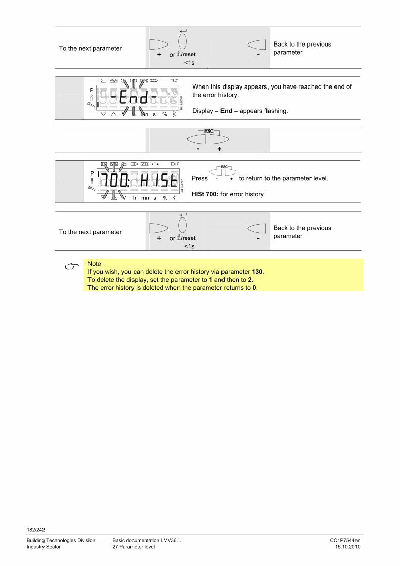
182/242
Building Technologies Division Basic documentation LMV36... CC1P7544en Industry Sector 27 Parameter level 15.10.2010
To the next parameter or /reset
<1s
Back to the previous parameter
P
V h min s %
Bild
92/
0707
When this display appears, you have reached the end of the error history. Display – End – appears flashing.
ESC
P
V h min s %
Bild
93/
0707
Press
ESC
to return to the parameter level. HISt 700: for error history
To the next parameter or /reset
<1s
Back to the previous parameter
Note If you wish, you can delete the error history via parameter 130. To delete the display, set the parameter to 1 and then to 2. The error history is deleted when the parameter returns to 0.

183/242
Building Technologies Division Basic documentation LMV36... CC1P7544en Industry Sector 27 Parameter level 15.10.2010
27.11 Fuel-air ratio curves – settings and commissioning
P
V h min s %
Bild
94/
0707
The display shows 400: flashing on the left, SEt appears on the right.
27.11.1 Initial commissioning
P
V h min s %
Bild
95/
0707
An unprogrammed unit or a unit whose operating mode has been reset or changed displays OFF UPR0 or OFF UPR1.
For initial commissioning, change to the parameter level (refer to chapter Operation). The settings can then be made on parameter level 400.
/reset
P
V h min s %
Bild
94/
0707
Press /reset to select parameter 400 for initial commis-sioning and for setting fuel-air ratio control.
/reset
P
V h min s %
Bild
96/
0707
Press /reset to go to the settings for fuel-air ratio control and parameter 201 for selecting the operating mode. 201: appears flashing.
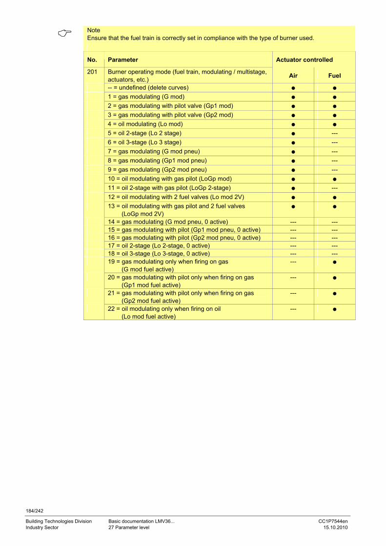
184/242
Building Technologies Division Basic documentation LMV36... CC1P7544en Industry Sector 27 Parameter level 15.10.2010
Note Ensure that the fuel train is correctly set in compliance with the type of burner used.
No. Parameter Actuator controlled
201 Burner operating mode (fuel train, modulating / multistage, actuators, etc.) Air Fuel
-- = undefined (delete curves) ● ● 1 = gas modulating (G mod) ● ● 2 = gas modulating with pilot valve (Gp1 mod) ● ● 3 = gas modulating with pilot valve (Gp2 mod) ● ● 4 = oil modulating (Lo mod) ● ● 5 = oil 2-stage (Lo 2 stage) ● --- 6 = oil 3-stage (Lo 3 stage) ● --- 7 = gas modulating (G mod pneu) ● --- 8 = gas modulating (Gp1 mod pneu) ● --- 9 = gas modulating (Gp2 mod pneu) ● --- 10 = oil modulating with gas pilot (LoGp mod) ● ● 11 = oil 2-stage with gas pilot (LoGp 2-stage) ● --- 12 = oil modulating with 2 fuel valves (Lo mod 2V) ● ● 13 = oil modulating with gas pilot and 2 fuel valves
(LoGp mod 2V) ● ●
14 = gas modulating (G mod pneu, 0 active) --- --- 15 = gas modulating with pilot (Gp1 mod pneu, 0 active) --- --- 16 = gas modulating with pilot (Gp2 mod pneu, 0 active) --- --- 17 = oil 2-stage (Lo 2-stage, 0 active) --- --- 18 = oil 3-stage (Lo 3-stage, 0 active) --- --- 19 = gas modulating only when firing on gas
(G mod fuel active) --- ●
20 = gas modulating with pilot only when firing on gas (Gp1 mod fuel active)
--- ●
21 = gas modulating with pilot only when firing on gas (Gp2 mod fuel active)
--- ●
22 = oil modulating only when firing on oil (Lo mod fuel active)
--- ●
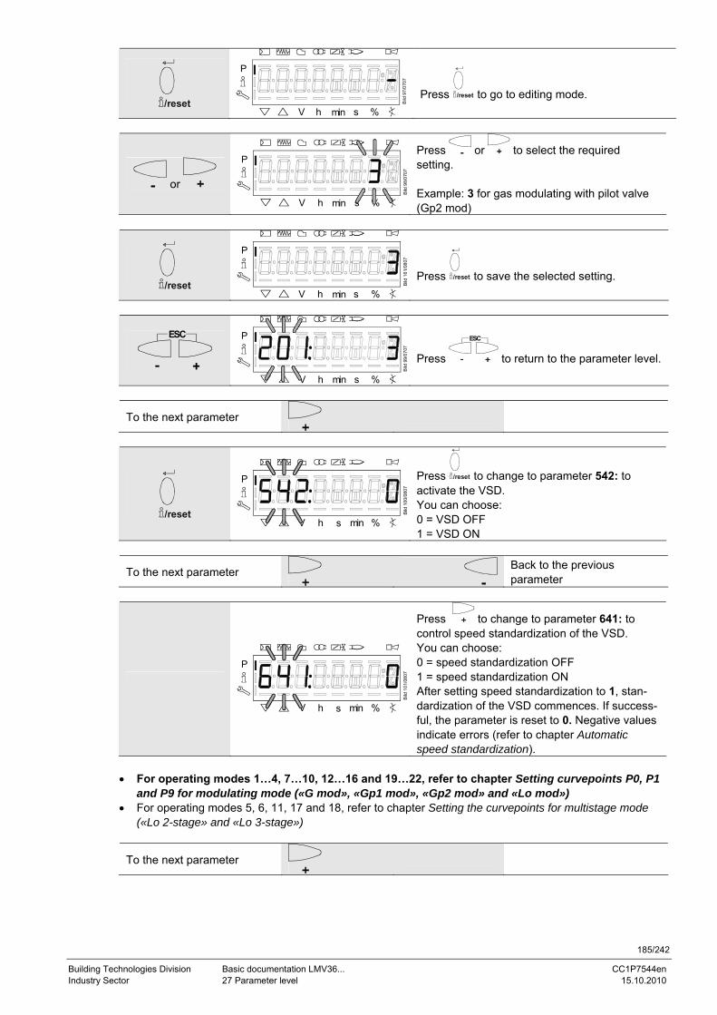
185/242
Building Technologies Division Basic documentation LMV36... CC1P7544en Industry Sector 27 Parameter level 15.10.2010
/reset
P
V h min s %
Bild
97/
0707
Press /reset to go to editing mode.
or
P
V h min s %
Bild
98/
0707
Press or to select the required setting. Example: 3 for gas modulating with pilot valve (Gp2 mod)
/reset
P
V h min s %
Bild
161
/080
7
Press /reset to save the selected setting.
ESC
P
V h min s %
Bild
99/
0707
Press
ESC
to return to the parameter level.
To the next parameter
/reset
P
V h s min %
Bild
100
/080
7
Press /reset to change to parameter 542: to activate the VSD. You can choose: 0 = VSD OFF 1 = VSD ON
To the next parameter
Back to the previous parameter
P
V h s min %
Bild
101
/080
7
Press to change to parameter 641: to control speed standardization of the VSD. You can choose: 0 = speed standardization OFF 1 = speed standardization ON After setting speed standardization to 1, stan-dardization of the VSD commences. If success-ful, the parameter is reset to 0. Negative values indicate errors (refer to chapter Automatic speed standardization).
• For operating modes 1…4, 7…10, 12…16 and 19…22, refer to chapter Setting curvepoints P0, P1
and P9 for modulating mode («G mod», «Gp1 mod», «Gp2 mod» and «Lo mod») • For operating modes 5, 6, 11, 17 and 18, refer to chapter Setting the curvepoints for multistage mode
(«Lo 2-stage» and «Lo 3-stage»)
To the next parameter
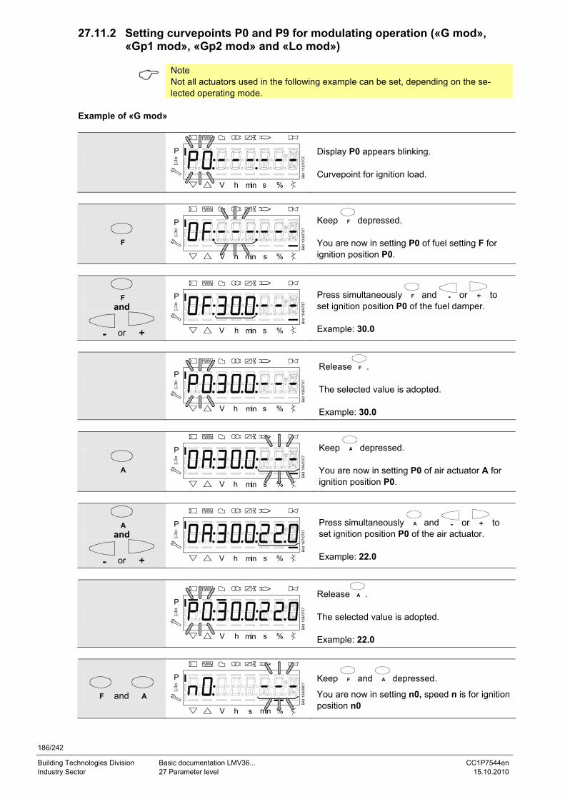
186/242
Building Technologies Division Basic documentation LMV36... CC1P7544en Industry Sector 27 Parameter level 15.10.2010
27.11.2 Setting curvepoints P0 and P9 for modulating operation («G mod», «Gp1 mod», «Gp2 mod» and «Lo mod»)
Note Not all actuators used in the following example can be set, depending on the se-lected operating mode.
Example of «G mod»
P
V h min s %
Bild
102
/070
7
Display P0 appears blinking. Curvepoint for ignition load.
F
P
V h min s %
Bild
103
/070
7
Keep F depressed. You are now in setting P0 of fuel setting F for ignition position P0.
F and
or
P
V h min s %
Bild
104
/070
7
Press simultaneously F and or to set ignition position P0 of the fuel damper. Example: 30.0
P
V h min s %
Bild
105
/070
7
Release F . The selected value is adopted. Example: 30.0
A
P
V h min s %
Bild
106
/070
7
Keep A depressed. You are now in setting P0 of air actuator A for ignition position P0.
A and
or
P
V h min s %
Bild
107
/070
7
Press simultaneously A and or to set ignition position P0 of the air actuator. Example: 22.0
P
V h min s %
Bild
108
/070
7
Release A . The selected value is adopted. Example: 22.0
F and A
P
V h s min %
Bild
109
/080
7
Keep F and A depressed.
You are now in setting n0, speed n is for ignition position n0
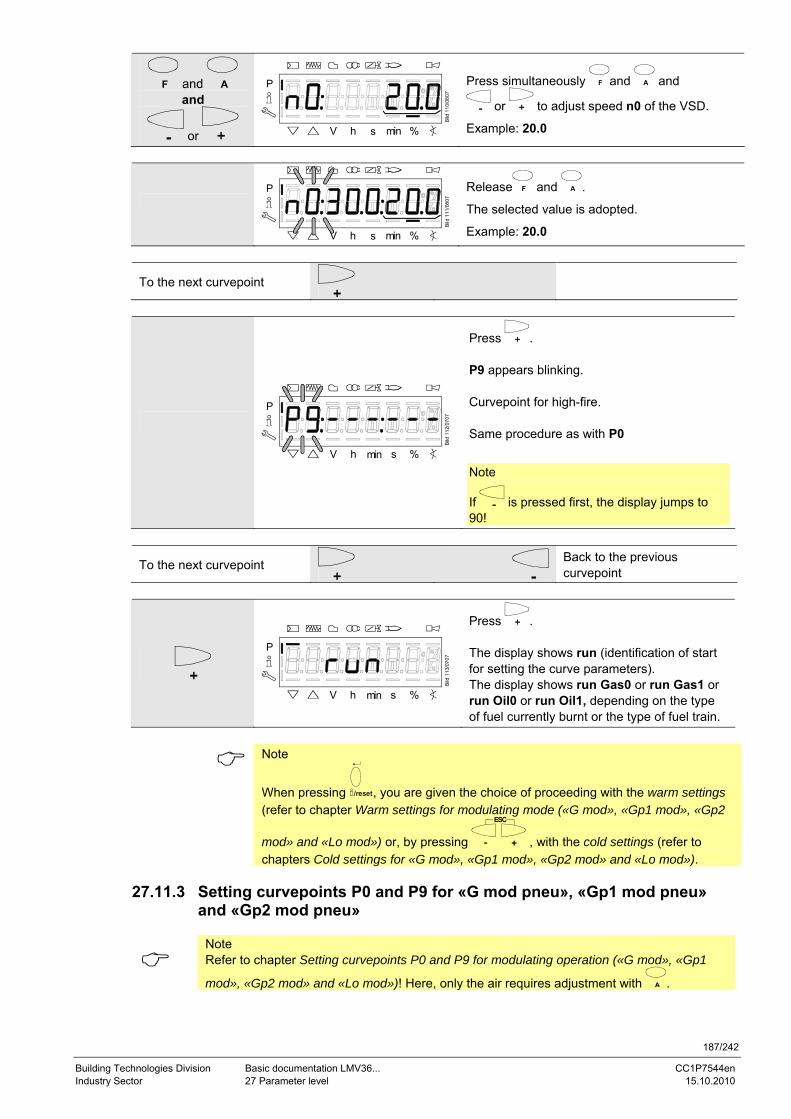
187/242
Building Technologies Division Basic documentation LMV36... CC1P7544en Industry Sector 27 Parameter level 15.10.2010
F and A and
or
P
V h s min %
Bild
110
/080
7
Press simultaneously F and A and
or to adjust speed n0 of the VSD.
Example: 20.0
P
V h s min %
Bild
111
/080
7
Release F and A .
The selected value is adopted.
Example: 20.0
To the next curvepoint
P
V h min s %B
ild 1
12/0
707
Press . P9 appears blinking. Curvepoint for high-fire. Same procedure as with P0
Note
If is pressed first, the display jumps to 90!
To the next curvepoint
Back to the previous curvepoint
P
V h min s %
Bild
113
/070
7
Press . The display shows run (identification of start for setting the curve parameters). The display shows run Gas0 or run Gas1 or run Oil0 or run Oil1, depending on the type of fuel currently burnt or the type of fuel train.
Note
When pressing /reset, you are given the choice of proceeding with the warm settings (refer to chapter Warm settings for modulating mode («G mod», «Gp1 mod», «Gp2
mod» and «Lo mod») or, by pressing
ESC
, with the cold settings (refer to chapters Cold settings for «G mod», «Gp1 mod», «Gp2 mod» and «Lo mod»).
27.11.3 Setting curvepoints P0 and P9 for «G mod pneu», «Gp1 mod pneu»
and «Gp2 mod pneu»
Note Refer to chapter Setting curvepoints P0 and P9 for modulating operation («G mod», «Gp1
mod», «Gp2 mod» and «Lo mod»)! Here, only the air requires adjustment with A .
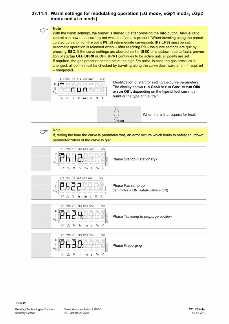
188/242
Building Technologies Division Basic documentation LMV36... CC1P7544en Industry Sector 27 Parameter level 15.10.2010
27.11.4 Warm settings for modulating operation («G mod», «Gp1 mod», «Gp2 mod» and «Lo mod»)
Note With the warm settings, the burner is started up after pressing the Info button. Air-fuel ratio control can now be accurately set while the flame is present. When traveling along the precal-culated curve to high-fire point P9, all intermediate curvepoints (P2…P8) must be set. Automatic operation is released when – after reaching P9 – the curve settings are quit by pressing ESC. If the curve settings are aborted earlier (ESC or shutdown due to fault), preven-tion of startup OFF UPR0 or OFF UPR1 continues to be active until all points are set. If required, the gas pressure can be set at the high-fire point. In case the gas pressure is changed, all points must be checked by traveling along the curve downward and – if required – readjusted.
P
V h min s %
Bild
113
/070
7
Identification of start for setting the curve parameters. The display shows run Gas0 or run Gas1 or run Oil0 or run Oil1, depending on the type of fuel currently burnt or the type of fuel train.
/reset
When there is a request for heat.
Note If, during the time the curve is parameterized, an error occurs which leads to safety shutdown, parameterization of the curve is quit.
P
V h min s %
Bild
114
/070
7
Phase Standby (stationary)
P
V h min s %
Bild
10/
0707
Phase Fan ramp up (fan motor = ON, safety valve = ON)
P
V h min s %
Bild
115
/070
7
Phase Traveling to prepurge position
P
V h min s %
Bild
116
/070
7
Phase Prepurging
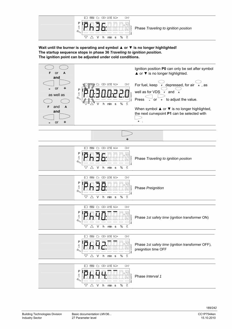
189/242
Building Technologies Division Basic documentation LMV36... CC1P7544en Industry Sector 27 Parameter level 15.10.2010
P
V h min s %
Bild
117
/070
7
Phase Traveling to ignition position
Wait until the burner is operating and symbol ▲ or ▼ is no longer highlighted! The startup sequence stops in phase 36 Traveling to ignition position. The ignition point can be adjusted under cold conditions.
F or A and
or
as well as
F and A and
or
P
V h min s %
Bild
118
/070
7
Ignition position P0 can only be set after symbol ▲ or ▼ is no longer highlighted.
For fuel, keep F depressed, for air A , as
well as for VDS F and A
Press or to adjust the value. When symbol ▲ or ▼ is no longer highlighted, the next curvepoint P1 can be selected with
.
P
V h min s %
Bild
117
/070
7
Phase Traveling to ignition position
P
V h min s %
Bild
119
/070
7
Phase Preignition
P
V h min s %
Bild
120
/070
7
Phase 1st safety time (ignition transformer ON)
P
V h min s %
Bild
121
/070
7 Phase 1st safety time (ignition transformer OFF), preignition time OFF
P
V h min s %
Bild
122
/070
7
Phase Interval 1
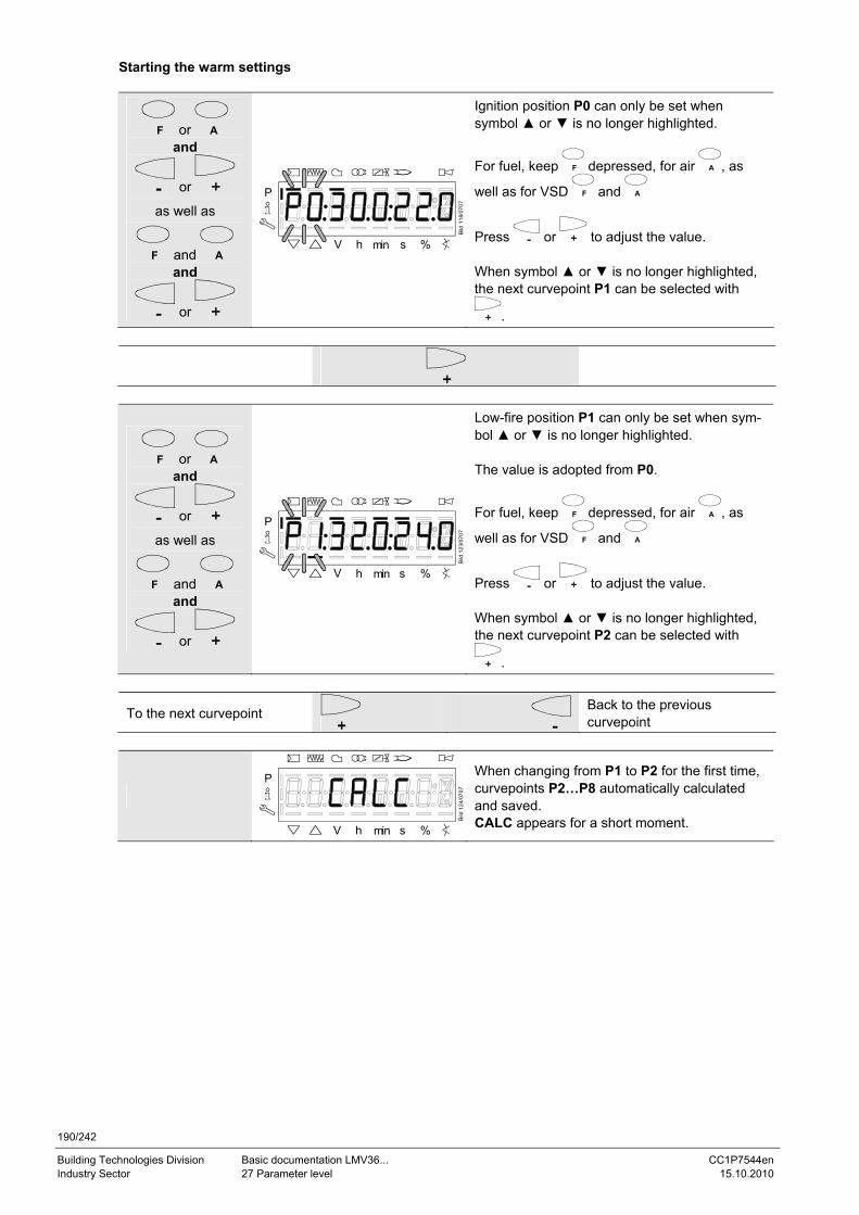
190/242
Building Technologies Division Basic documentation LMV36... CC1P7544en Industry Sector 27 Parameter level 15.10.2010
Starting the warm settings
F or A and
or
as well as
F and A and
or
P
V h min s %
Bild
118
/070
7
Ignition position P0 can only be set when symbol ▲ or ▼ is no longer highlighted.
For fuel, keep F depressed, for air A , as
well as for VSD F and A
Press or to adjust the value. When symbol ▲ or ▼ is no longer highlighted, the next curvepoint P1 can be selected with
.
F or A and
or
as well as
F and A and
or
P
V h min s %
Bild
123
/070
7
Low-fire position P1 can only be set when sym-bol ▲ or ▼ is no longer highlighted. The value is adopted from P0.
For fuel, keep F depressed, for air A , as
well as for VSD F and A
Press or to adjust the value. When symbol ▲ or ▼ is no longer highlighted, the next curvepoint P2 can be selected with
.
To the next curvepoint
Back to the previous curvepoint
P
V h min s %
Bild
124
/070
7
When changing from P1 to P2 for the first time, curvepoints P2…P8 automatically calculated and saved. CALC appears for a short moment.
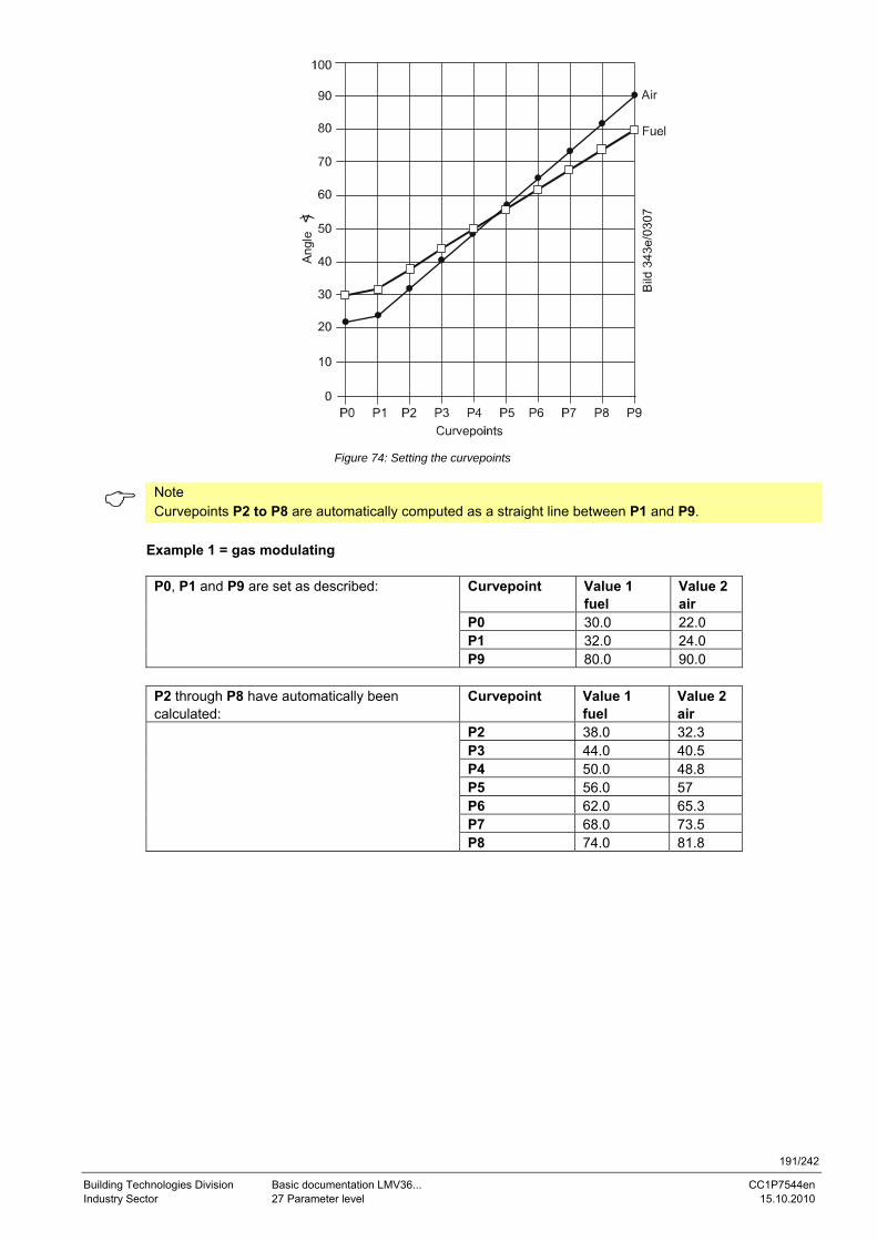
191/242
Building Technologies Division Basic documentation LMV36... CC1P7544en Industry Sector 27 Parameter level 15.10.2010
)
Air
Figure 74: Setting the curvepoints
Note Curvepoints P2 to P8 are automatically computed as a straight line between P1 and P9.
Example 1 = gas modulating
Curvepoint Value 1 fuel
Value 2 air
P0 30.0 22.0 P1 32.0 24.0
P0, P1 and P9 are set as described:
P9 80.0 90.0
P2 through P8 have automatically been calculated:
Curvepoint Value 1 fuel
Value 2 air
P2 38.0 32.3 P3 44.0 40.5 P4 50.0 48.8 P5 56.0 57 P6 62.0 65.3 P7 68.0 73.5
P8 74.0 81.8
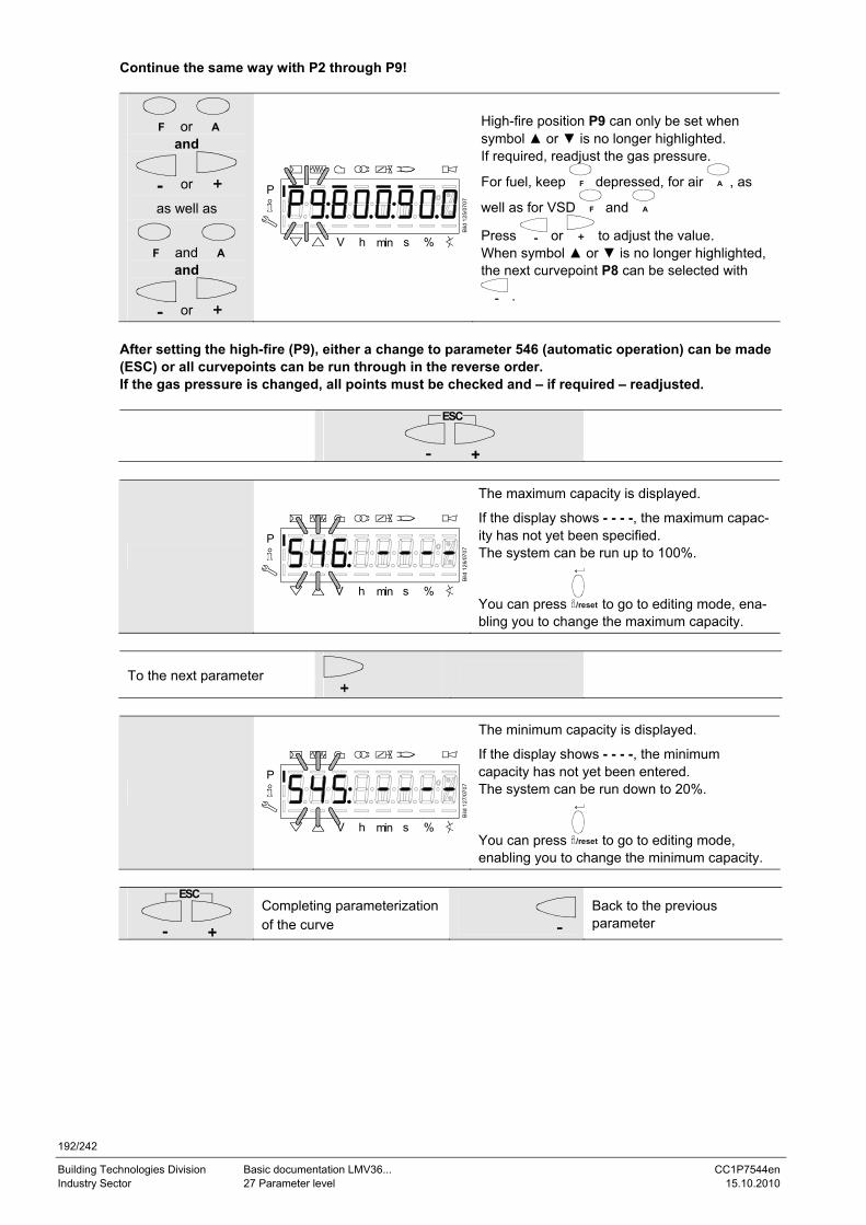
192/242
Building Technologies Division Basic documentation LMV36... CC1P7544en Industry Sector 27 Parameter level 15.10.2010
Continue the same way with P2 through P9!
F or A and
or
as well as
F and A and
or
P
V h min s %
Bild
125
/070
7
High-fire position P9 can only be set when symbol ▲ or ▼ is no longer highlighted. If required, readjust the gas pressure.
For fuel, keep F depressed, for air A , as
well as for VSD F and A
Press or to adjust the value. When symbol ▲ or ▼ is no longer highlighted, the next curvepoint P8 can be selected with
.
After setting the high-fire (P9), either a change to parameter 546 (automatic operation) can be made (ESC) or all curvepoints can be run through in the reverse order. If the gas pressure is changed, all points must be checked and – if required – readjusted.
ESC
P
V h min s %
Bild
126
/070
7
The maximum capacity is displayed.
If the display shows - - - -, the maximum capac-ity has not yet been specified. The system can be run up to 100%.
You can press /reset to go to editing mode, ena-bling you to change the maximum capacity.
To the next parameter
P
V h min s %
Bild
127
/070
7
The minimum capacity is displayed.
If the display shows - - - -, the minimum capacity has not yet been entered. The system can be run down to 20%.
You can press /reset to go to editing mode, enabling you to change the minimum capacity.
ESC
Completing parameterization of the curve
Back to the previous parameter
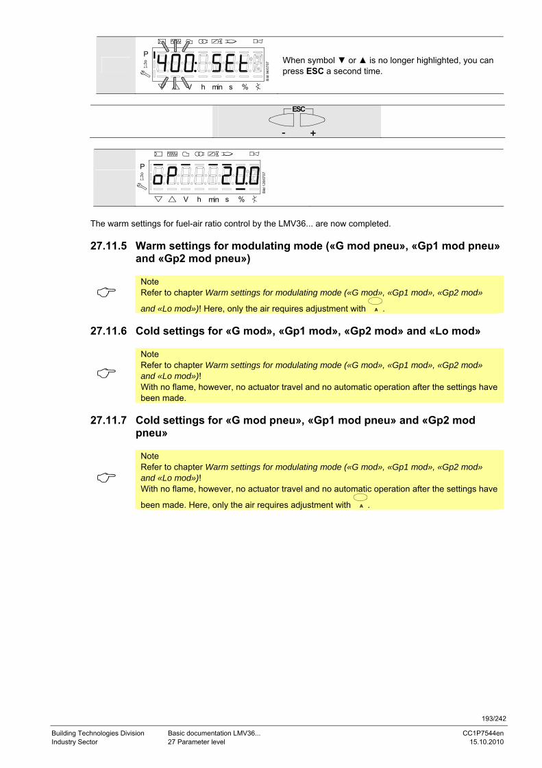
193/242
Building Technologies Division Basic documentation LMV36... CC1P7544en Industry Sector 27 Parameter level 15.10.2010
P
V h min s %
Bild
94/
0707
When symbol ▼ or ▲ is no longer highlighted, you can press ESC a second time.
ESC
P
V h min s %
Bild
128
/070
7
The warm settings for fuel-air ratio control by the LMV36... are now completed. 27.11.5 Warm settings for modulating mode («G mod pneu», «Gp1 mod pneu»
and «Gp2 mod pneu»)
Note Refer to chapter Warm settings for modulating mode («G mod», «Gp1 mod», «Gp2 mod»
and «Lo mod»)! Here, only the air requires adjustment with A . 27.11.6 Cold settings for «G mod», «Gp1 mod», «Gp2 mod» and «Lo mod»
Note Refer to chapter Warm settings for modulating mode («G mod», «Gp1 mod», «Gp2 mod» and «Lo mod»)! With no flame, however, no actuator travel and no automatic operation after the settings have been made.
27.11.7 Cold settings for «G mod pneu», «Gp1 mod pneu» and «Gp2 mod
pneu»
Note Refer to chapter Warm settings for modulating mode («G mod», «Gp1 mod», «Gp2 mod» and «Lo mod»)! With no flame, however, no actuator travel and no automatic operation after the settings have
been made. Here, only the air requires adjustment with A .
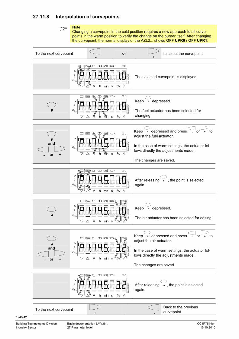
194/242
Building Technologies Division Basic documentation LMV36... CC1P7544en Industry Sector 27 Parameter level 15.10.2010
27.11.8 Interpolation of curvepoints
Note Changing a curvepoint in the cold position requires a new approach to all curve-points in the warm position to verify the change on the burner itself. After changing the curvepoint, the normal display of the AZL2... shows OFF UPR0 / OFF UPR1.
To the next curvepoint
or
to select the curvepoint
P
V h min s %
Bild
129
/070
7
The selected curvepoint is displayed.
F
P
V h min s %
Bild
130
/070
7
Keep F depressed. The fuel actuator has been selected for changing.
F and
or
P
V h min s %
Bild
131
/070
7
Keep F depressed and press or to adjust the fuel actuator. In the case of warm settings, the actuator fol-lows directly the adjustments made. The changes are saved.
P
V h min s %
Bild
132
/070
7
After releasing F , the point is selected again.
A
P
V h min s %
Bild
133
/070
7
Keep A depressed. The air actuator has been selected for editing.
A and
or
P
V h min s %
Bild
134
/070
7
Keep A depressed and press or to adjust the air actuator. In the case of warm settings, the actuator fol-lows directly the adjustments made. The changes are saved.
P
V h min s %
Bild
135
/070
7
After releasing A , the point is selected again.
To the next curvepoint
Back to the previous curvepoint
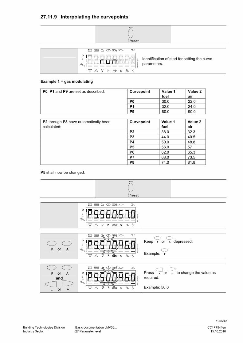
195/242
Building Technologies Division Basic documentation LMV36... CC1P7544en Industry Sector 27 Parameter level 15.10.2010
27.11.9 Interpolating the curvepoints
/reset
P
V h min s %
Bild
113
/070
7 Identification of start for setting the curve parameters.
Example 1 = gas modulating
Curvepoint Value 1 fuel
Value 2 air
P0 30.0 22.0 P1 32.0 24.0
P0, P1 and P9 are set as described:
P9 80.0 90.0
P2 through P8 have automatically been calculated:
Curvepoint Value 1 fuel
Value 2 air
P2 38.0 32.3 P3 44.0 40.5 P4 50.0 48.8 P5 56.0 57 P6 62.0 65.3 P7 68.0 73.5
P8 74.0 81.8 P5 shall now be changed:
/reset
P
V h min s %
Bild
136
/070
7
F or A
P
V h min s %
Bild
137
/070
7
Keep F or A depressed.
Example: F
F or A and
or
P
V h min s %
Bild
138
/070
7
Press or to change the value as required. Example: 50.0
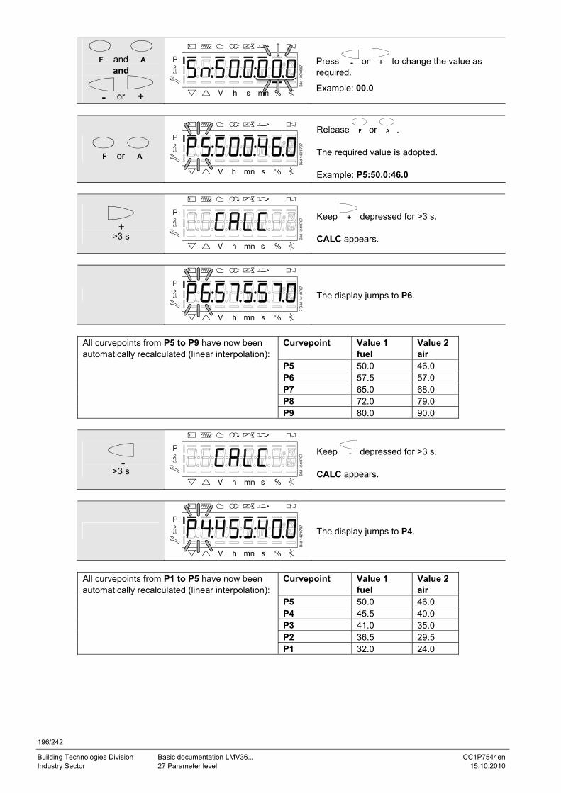
196/242
Building Technologies Division Basic documentation LMV36... CC1P7544en Industry Sector 27 Parameter level 15.10.2010
F and A and
or
P
V h s min %
Bild
139
/080
7
Press or to change the value as required.
Example: 00.0
F or A
P
V h min s %
Bild
140
/070
7
Release F or A . The required value is adopted. Example: P5:50.0:46.0
>3 s
P
V h min s %
Bild
124
/070
7
Keep depressed for >3 s. CALC appears.
P
V h min s %
7´B
ild 1
41/0
707
The display jumps to P6.
Curvepoint Value 1
fuel Value 2 air
P5 50.0 46.0 P6 57.5 57.0 P7 65.0 68.0 P8 72.0 79.0
All curvepoints from P5 to P9 have now been automatically recalculated (linear interpolation):
P9 80.0 90.0
>3 s
P
V h min s %
Bild
124
/070
7
Keep depressed for >3 s. CALC appears.
P
V h min s %
Bild
142
/070
7
The display jumps to P4.
Curvepoint Value 1
fuel Value 2 air
P5 50.0 46.0 P4 45.5 40.0 P3 41.0 35.0 P2 36.5 29.5
All curvepoints from P1 to P5 have now been automatically recalculated (linear interpolation):
P1 32.0 24.0
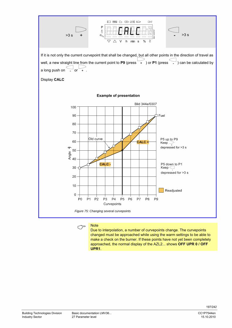
197/242
Building Technologies Division Basic documentation LMV36... CC1P7544en Industry Sector 27 Parameter level 15.10.2010
>3 s
P
V h min s %
Bild
124
/070
7
>3 s
If it is not only the current curvepoint that shall be changed, but all other points in the direction of travel as
well, a new straight line from the current point to P9 (press ) or P1 (press ) can be calculated by
a long push on or . Display CALC
Example of presentation
)
P5 down to P1Keep depressed for >3 s
P5 up to P9Keep depressed for >3 s
CALC -
CALC +
Figure 75: Changing several curvepoints
Note Due to interpolation, a number of curvepoints change. The curvepoints changed must be approached while using the warm settings to be able to make a check on the burner. If these points have not yet been completely approached, the normal display of the AZL2... shows OFF UPR 0 / OFF UPR1.
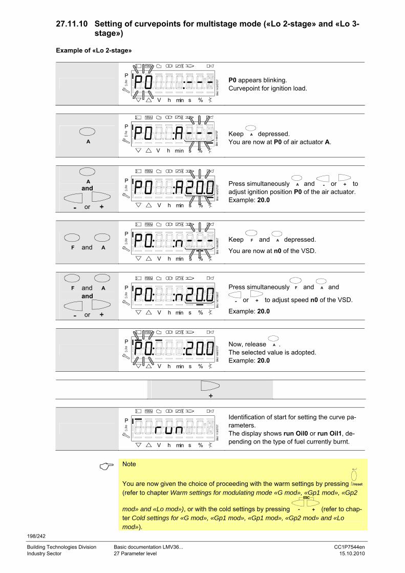
198/242
Building Technologies Division Basic documentation LMV36... CC1P7544en Industry Sector 27 Parameter level 15.10.2010
27.11.10 Setting of curvepoints for multistage mode («Lo 2-stage» and «Lo 3-stage»)
Example of «Lo 2-stage»
P
V h min s %
Bild
143
/070
7
P0 appears blinking. Curvepoint for ignition load.
A
Bild
144
/070
7
P
V h min s %
Keep A depressed. You are now at P0 of air actuator A.
A and
or
P
V h min s %
Bild
145
/070
7
Press simultaneously A and or to adjust ignition position P0 of the air actuator. Example: 20.0
F and A
P
V h min s %
Bild
146
/080
7
Keep F and A depressed.
You are now at n0 of the VSD.
F and A and
or
P
V h min s %
Bild
147
/080
7
Press simultaneously F and A and
or to adjust speed n0 of the VSD.
Example: 20.0
P
V h min s %
Bild
148
/070
7
Now, release A . The selected value is adopted. Example: 20.0
P
V h min s %
Bild
113
/070
7
Identification of start for setting the curve pa-rameters. The display shows run Oil0 or run Oil1, de-pending on the type of fuel currently burnt.
Note
You are now given the choice of proceeding with the warm settings by pressing /reset (refer to chapter Warm settings for modulating mode «G mod», «Gp1 mod», «Gp2
mod» and «Lo mod»), or with the cold settings by pressing
ESC
(refer to chap-ter Cold settings for «G mod», «Gp1 mod», «Gp1 mod», «Gp2 mod» and «Lo mod»).
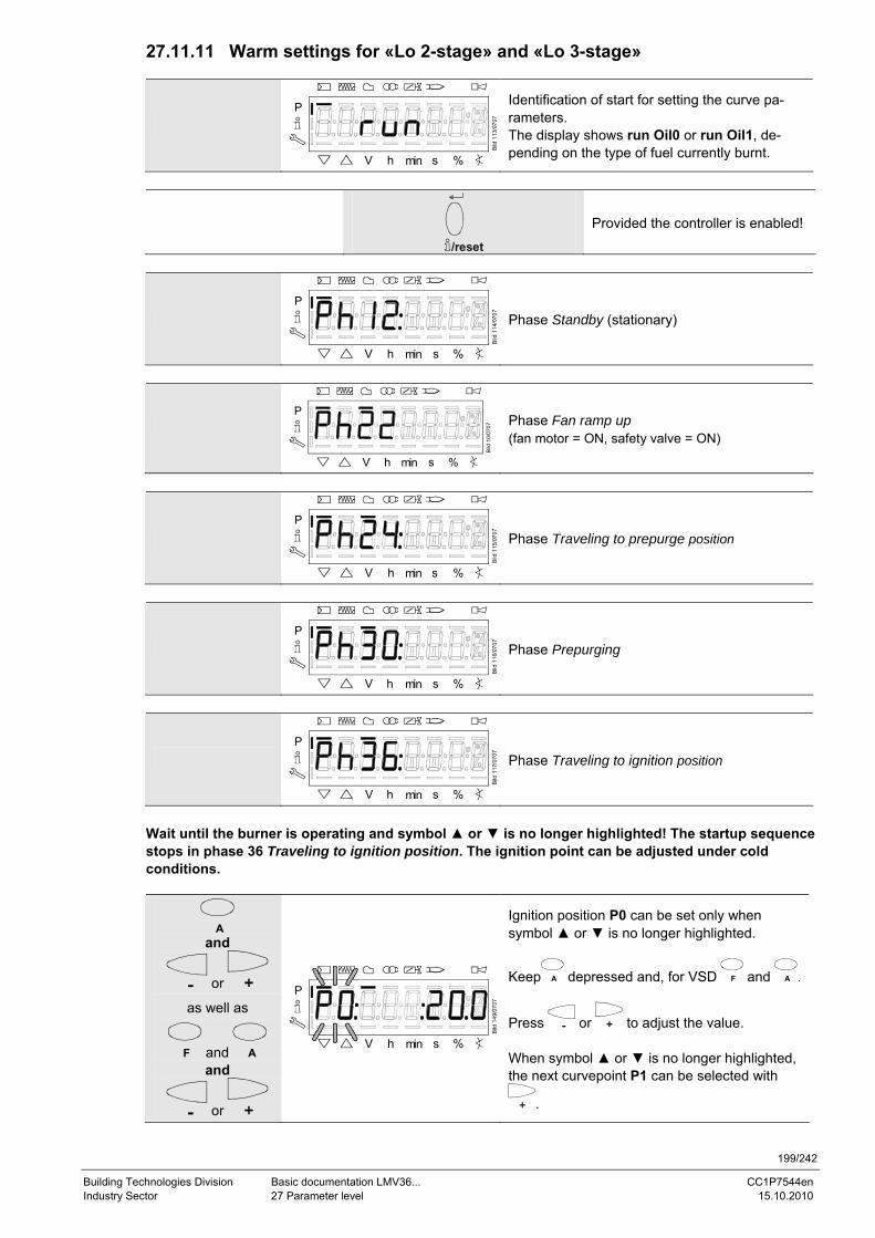
199/242
Building Technologies Division Basic documentation LMV36... CC1P7544en Industry Sector 27 Parameter level 15.10.2010
27.11.11 Warm settings for «Lo 2-stage» and «Lo 3-stage»
P
V h min s %
Bild
113
/070
7
Identification of start for setting the curve pa-rameters. The display shows run Oil0 or run Oil1, de-pending on the type of fuel currently burnt.
/reset
Provided the controller is enabled!
P
V h min s %
Bild
114
/070
7
Phase Standby (stationary)
P
V h min s %
Bild
10/
0707
Phase Fan ramp up (fan motor = ON, safety valve = ON)
P
V h min s %
Bild
115
/070
7
Phase Traveling to prepurge position
P
V h min s %
Bild
116
/070
7
Phase Prepurging
P
V h min s %
Bild
117
/070
7
Phase Traveling to ignition position
Wait until the burner is operating and symbol ▲ or ▼ is no longer highlighted! The startup sequence stops in phase 36 Traveling to ignition position. The ignition point can be adjusted under cold conditions.
A and
or
as well as
F and A and
or
P
V h min s %
Bild
149
/070
7
Ignition position P0 can be set only when symbol ▲ or ▼ is no longer highlighted.
Keep A depressed and, for VSD F and A .
Press or to adjust the value. When symbol ▲ or ▼ is no longer highlighted, the next curvepoint P1 can be selected with
.
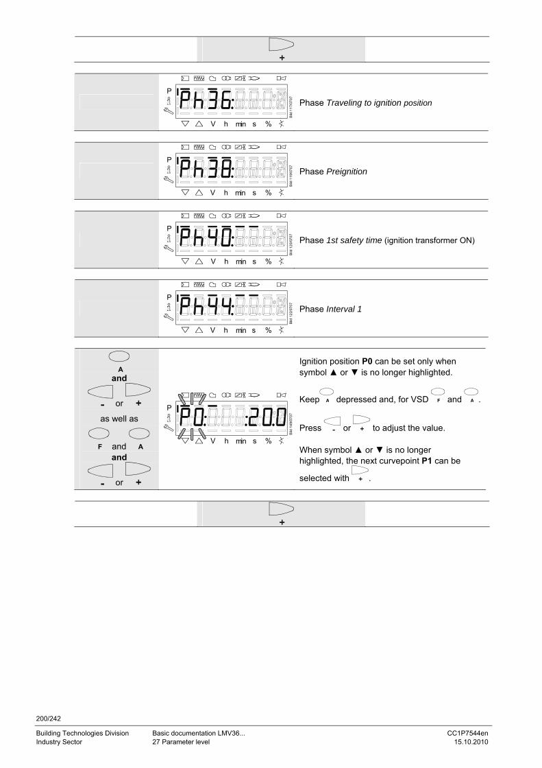
200/242
Building Technologies Division Basic documentation LMV36... CC1P7544en Industry Sector 27 Parameter level 15.10.2010
P
V h min s %
Bild
117
/070
7
Phase Traveling to ignition position
P
V h min s %
Bild
119
/070
7
Phase Preignition
P
V h min s %
Bild
120
/070
7
Phase 1st safety time (ignition transformer ON)
P
V h min s %
Bild
122
/070
7
Phase Interval 1
A and
or
as well as
F and A and
or
P
V h min s %
Bild
149
/070
7
Ignition position P0 can be set only when symbol ▲ or ▼ is no longer highlighted.
Keep A depressed and, for VSD F and A .
Press or to adjust the value. When symbol ▲ or ▼ is no longer highlighted, the next curvepoint P1 can be
selected with .
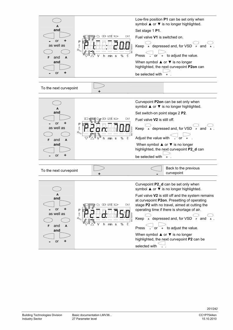
201/242
Building Technologies Division Basic documentation LMV36... CC1P7544en Industry Sector 27 Parameter level 15.10.2010
A and
or as well as
F and A and
or
P
V h min s %
Bild
150
/070
7
Low-fire position P1 can be set only when symbol ▲ or ▼ is no longer highlighted.
Set stage 1 P1.
Fuel valve V1 is switched on.
Keep A depressed and, for VSD F and A .
Press or to adjust the value.
When symbol ▲ or ▼ is no longer highlighted, the next curvepoint P2on can
be selected with .
To the next curvepoint
A and
or as well as
F and A and
or
P
V h min s %
Bild
151
/070
7
Curvepoint P2on can be set only when symbol ▲ or ▼ is no longer highlighted.
Set switch-on point stage 2 P2.
Fuel valve V2 is still off.
Keep A depressed and, for VSD F and A .
Adjust the value with or .
When symbol ▲ or ▼ is no longer highlighted, the next curvepoint P2_d can
be selected with .
To the next curvepoint
Back to the previous curvepoint
A and
or as well as
F and A and
or
P
V h min s %
Bild
152
/070
7
Curvepoint P2_d can be set only when symbol ▲ or ▼ is no longer highlighted.
Fuel valve V2 is still off and the system remains at curvepoint P2on. Presetting of operating stage P2 with no travel, aimed at cutting the operating time if there is shortage of air.
Keep A depressed and, for VSD F and A .
Press or to adjust the value.
When symbol ▲ or ▼ is no longer highlighted, the next curvepoint P2 can be
selected with .
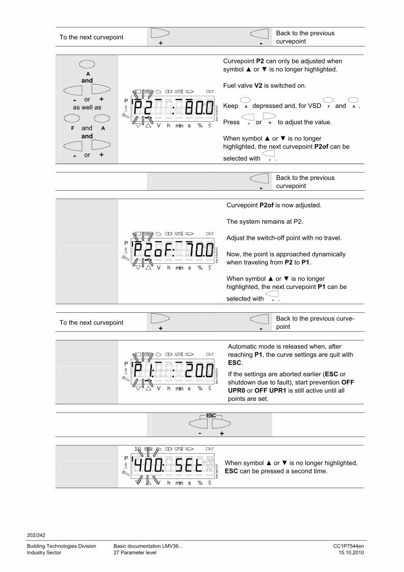
202/242
Building Technologies Division Basic documentation LMV36... CC1P7544en Industry Sector 27 Parameter level 15.10.2010
To the next curvepoint
Back to the previous curvepoint
A and
or as well as
F and A and
or
P
V h min s %
Bild
153
/070
7
Curvepoint P2 can only be adjusted when symbol ▲ or ▼ is no longer highlighted. Fuel valve V2 is switched on.
Keep A depressed and, for VSD F and A .
Press or to adjust the value. When symbol ▲ or ▼ is no longer highlighted, the next curvepoint P2of can be
selected with .
Back to the previous curvepoint
P
V h min s %
Bild
154
/070
7
Curvepoint P2of is now adjusted. The system remains at P2. Adjust the switch-off point with no travel. Now, the point is approached dynamically when traveling from P2 to P1. When symbol ▲ or ▼ is no longer highlighted, the next curvepoint P1 can be
selected with .
To the next curvepoint
Back to the previous curve-point
P
V h min s %
Bild
155
/070
7
Automatic mode is released when, after reaching P1, the curve settings are quit with ESC.
If the settings are aborted earlier (ESC or shutdown due to fault), start prevention OFF UPR0 or OFF UPR1 is still active until all points are set.
ESC
P
V h min s %
Bild
94/
0707 When symbol ▲ or ▼ is no longer highlighted,
ESC can be pressed a second time.
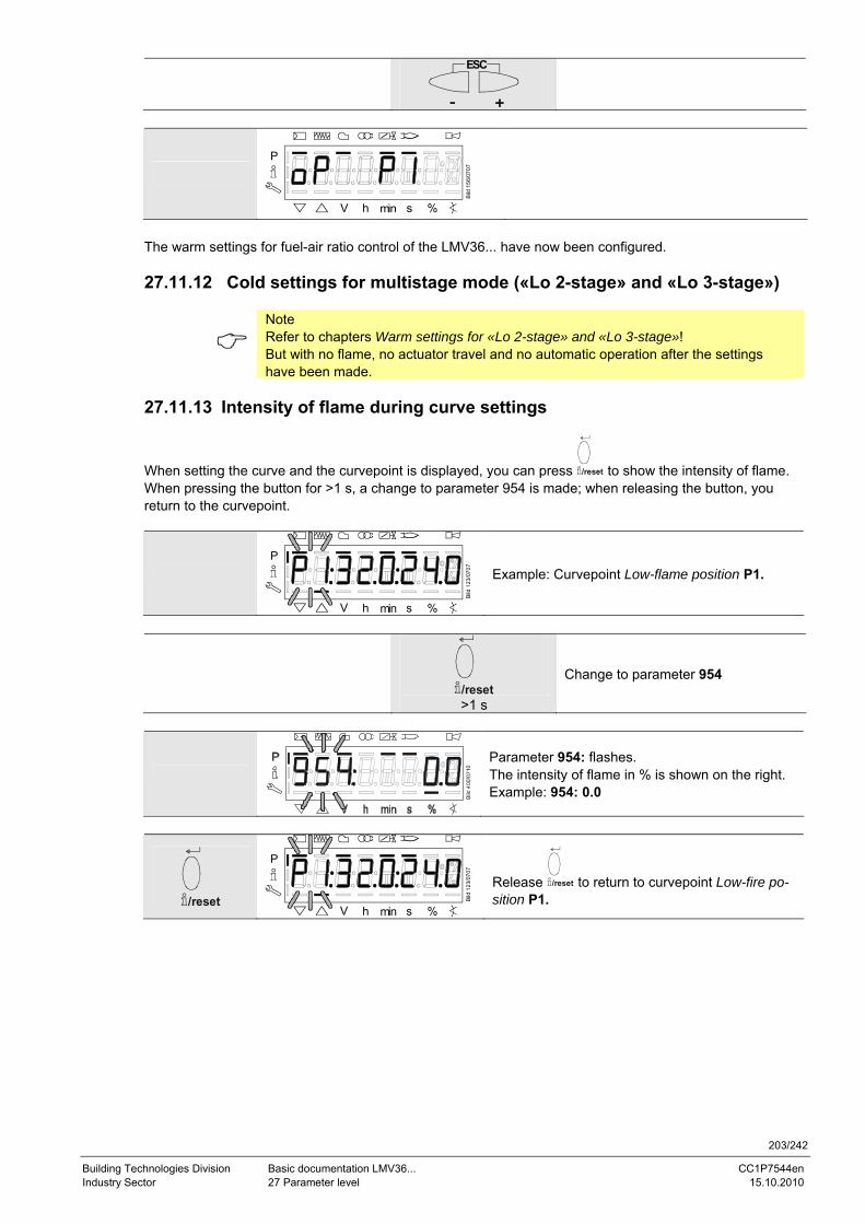
203/242
Building Technologies Division Basic documentation LMV36... CC1P7544en Industry Sector 27 Parameter level 15.10.2010
ESC
P
V h min s %
Bild
156
/070
7
The warm settings for fuel-air ratio control of the LMV36... have now been configured. 27.11.12 Cold settings for multistage mode («Lo 2-stage» and «Lo 3-stage»)
Note Refer to chapters Warm settings for «Lo 2-stage» and «Lo 3-stage»! But with no flame, no actuator travel and no automatic operation after the settings have been made.
27.11.13 Intensity of flame during curve settings
When setting the curve and the curvepoint is displayed, you can press /reset to show the intensity of flame. When pressing the button for >1 s, a change to parameter 954 is made; when releasing the button, you return to the curvepoint.
P
V h min s %
Bild
123
/070
7
Example: Curvepoint Low-flame position P1.
/reset >1 s
Change to parameter 954
Parameter 954: flashes. The intensity of flame in % is shown on the right. Example: 954: 0.0
/reset
P
V h min s %
Bild
123
/070
7
Release /reset to return to curvepoint Low-fire po-sition P1.
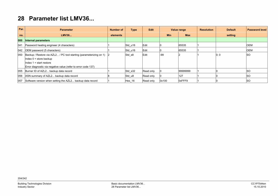
204/242
Building Technologies Division Basic documentation LMV36... CC1P7544en Industry Sector 28 Parameter list LMV36... 15.10.2010
28 Parameter list LMV36... Par. Parameter Number of Type Edit Value range Resolution Default Password level
no. LMV36... elements Min Max setting
000 Internal parameters
041 Password heating engineer (4 characters) 1 Std_u16 Edit 0 65535 1 OEM
042 OEM password (5 characters) 1 Std_u16 Edit 0 65535 1 OEM
050 Backup / Restore via AZL2... / PC tool starting (parameterizing on 1)Index 0 = store backup Index 1 = start restore Error diagnostic via negative value (refer to error code 137)
2 Std_s8 Edit -99 2 1 0; 0 SO
055 Burner ID of AZL2... backup data record 1 Std_s32 Read only 0 99999999 1 0 SO
056 ASN summary of AZL2... backup data record 8 Std_u8 Read only 0 127 1 0 SO
057 Software version when setting the AZL2... backup data record 1 Hex_16 Read only 0x100 0xFFF9 1 0 SO
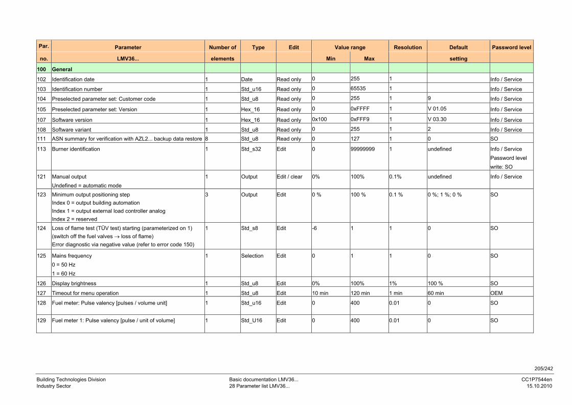
205/242
Building Technologies Division Basic documentation LMV36... CC1P7544en Industry Sector 28 Parameter list LMV36... 15.10.2010
Par. Parameter Number of Type Edit Value range Resolution Default Password level
no. LMV36... elements Min Max setting
100 General
102 Identification date 1 Date Read only 0 255 1 Info / Service
103 Identification number 1 Std_u16 Read only 0 65535 1 Info / Service
104 Preselected parameter set: Customer code 1 Std_u8 Read only 0 255 1 9 Info / Service
105 Preselected parameter set: Version 1 Hex_16 Read only 0 0xFFFF 1 V 01.05 Info / Service
107 Software version 1 Hex_16 Read only 0x100 0xFFF9 1 V 03.30 Info / Service
108 Software variant 1 Std_u8 Read only 0 255 1 2 Info / Service 111 ASN summary for verification with AZL2... backup data restore 8 Std_u8 Read only 0 127 1 0 SO
113 Burner identification 1 Std_s32 Edit 0 99999999 1 undefined Info / Service Password level write: SO
121 Manual output Undefined = automatic mode
1 Output Edit / clear 0% 100% 0.1% undefined Info / Service
123 Minimum output positioning step Index 0 = output building automation Index 1 = output external load controller analog Index 2 = reserved
3 Output Edit 0 % 100 % 0.1 % 0 %; 1 %; 0 % SO
124 Loss of flame test (TÜV test) starting (parameterized on 1) (switch off the fuel valves → loss of flame) Error diagnostic via negative value (refer to error code 150)
1 Std_s8 Edit -6 1 1 0 SO
125 Mains frequency 0 = 50 Hz 1 = 60 Hz
1 Selection Edit 0 1 1 0 SO
126 Display brightness 1 Std_u8 Edit 0% 100% 1% 100 % SO
127 Timeout for menu operation 1 Std_u8 Edit 10 min 120 min 1 min 60 min OEM
128 Fuel meter: Pulse valency [pulses / volume unit] 1 Std_u16 Edit 0 400 0.01 0 SO
129 Fuel meter 1: Pulse valency [pulse / unit of volume] 1 Std_U16 Edit 0 400 0.01 0 SO
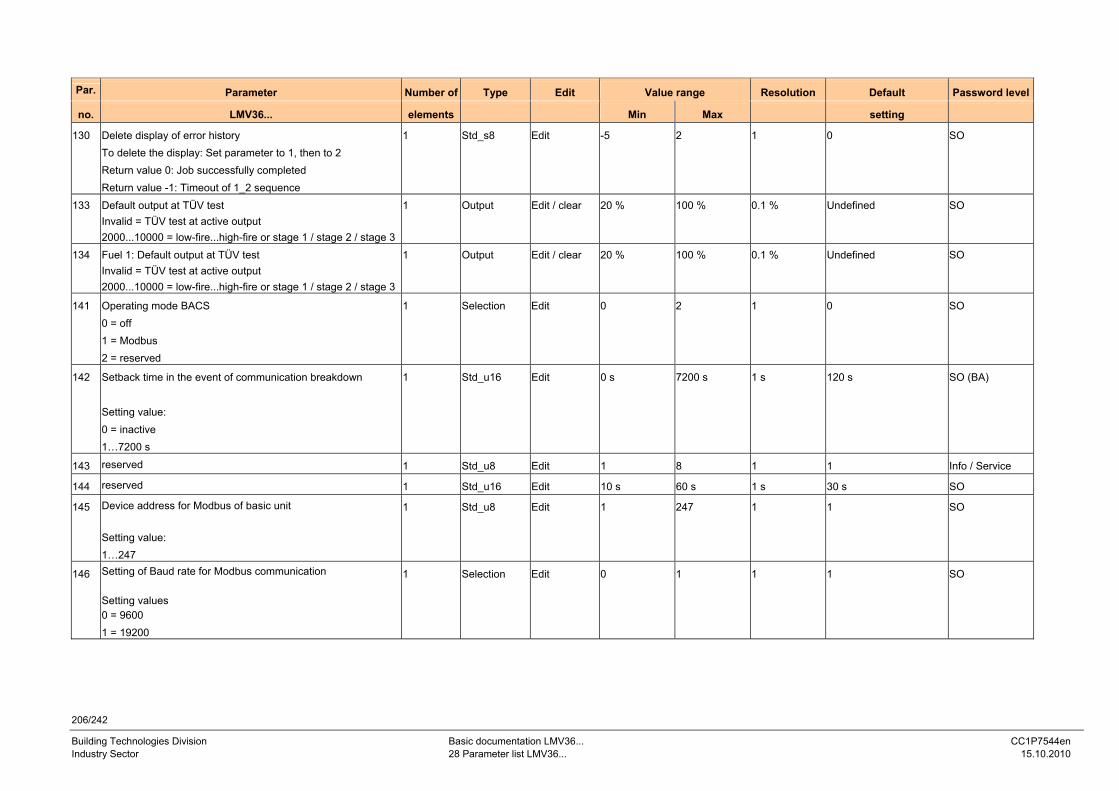
206/242
Building Technologies Division Basic documentation LMV36... CC1P7544en Industry Sector 28 Parameter list LMV36... 15.10.2010
Par. Parameter Number of Type Edit Value range Resolution Default Password level
no. LMV36... elements Min Max setting
130 Delete display of error history To delete the display: Set parameter to 1, then to 2 Return value 0: Job successfully completed Return value -1: Timeout of 1_2 sequence
1 Std_s8 Edit -5 2 1 0 SO
133 Default output at TÜV test Invalid = TÜV test at active output 2000...10000 = low-fire...high-fire or stage 1 / stage 2 / stage 3
1 Output Edit / clear 20 % 100 % 0.1 % Undefined SO
134 Fuel 1: Default output at TÜV test Invalid = TÜV test at active output 2000...10000 = low-fire...high-fire or stage 1 / stage 2 / stage 3
1 Output Edit / clear 20 % 100 % 0.1 % Undefined SO
141 Operating mode BACS 0 = off 1 = Modbus 2 = reserved
1 Selection Edit 0 2 1 0 SO
142 Setback time in the event of communication breakdown Setting value: 0 = inactive 1…7200 s
1 Std_u16 Edit 0 s 7200 s 1 s 120 s SO (BA)
143 reserved 1 Std_u8 Edit 1 8 1 1 Info / Service
144 reserved 1 Std_u16 Edit 10 s 60 s 1 s 30 s SO
145 Device address for Modbus of basic unit Setting value: 1…247
1 Std_u8 Edit 1 247 1 1 SO
146 Setting of Baud rate for Modbus communication Setting values 0 = 9600 1 = 19200
1 Selection Edit 0 1 1 1 SO
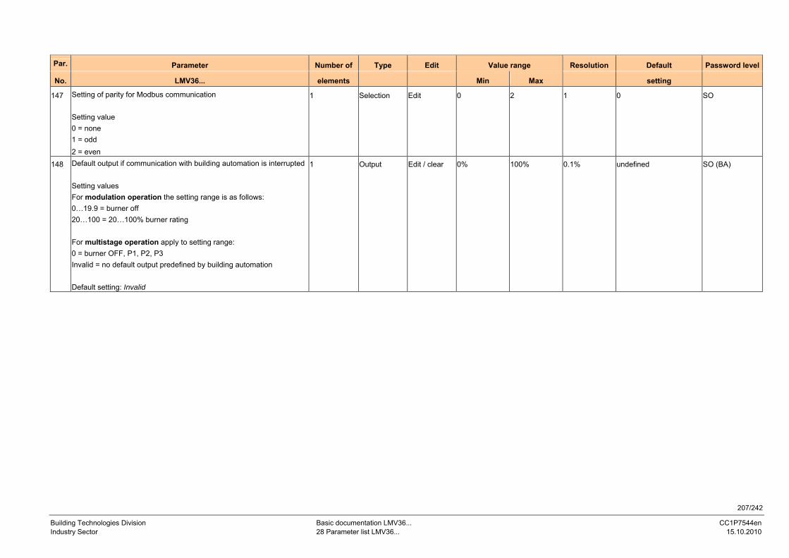
207/242
Building Technologies Division Basic documentation LMV36... CC1P7544en Industry Sector 28 Parameter list LMV36... 15.10.2010
Par. Parameter Number of Type Edit Value range Resolution Default Password level
No. LMV36... elements Min Max setting
147 Setting of parity for Modbus communication Setting value 0 = none 1 = odd 2 = even
1 Selection Edit 0 2 1 0 SO
148 Default output if communication with building automation is interrupted Setting values For modulation operation the setting range is as follows: 0…19.9 = burner off 20…100 = 20…100% burner rating For multistage operation apply to setting range: 0 = burner OFF, P1, P2, P3 Invalid = no default output predefined by building automation Default setting: Invalid
1 Output Edit / clear 0% 100% 0.1% undefined SO (BA)
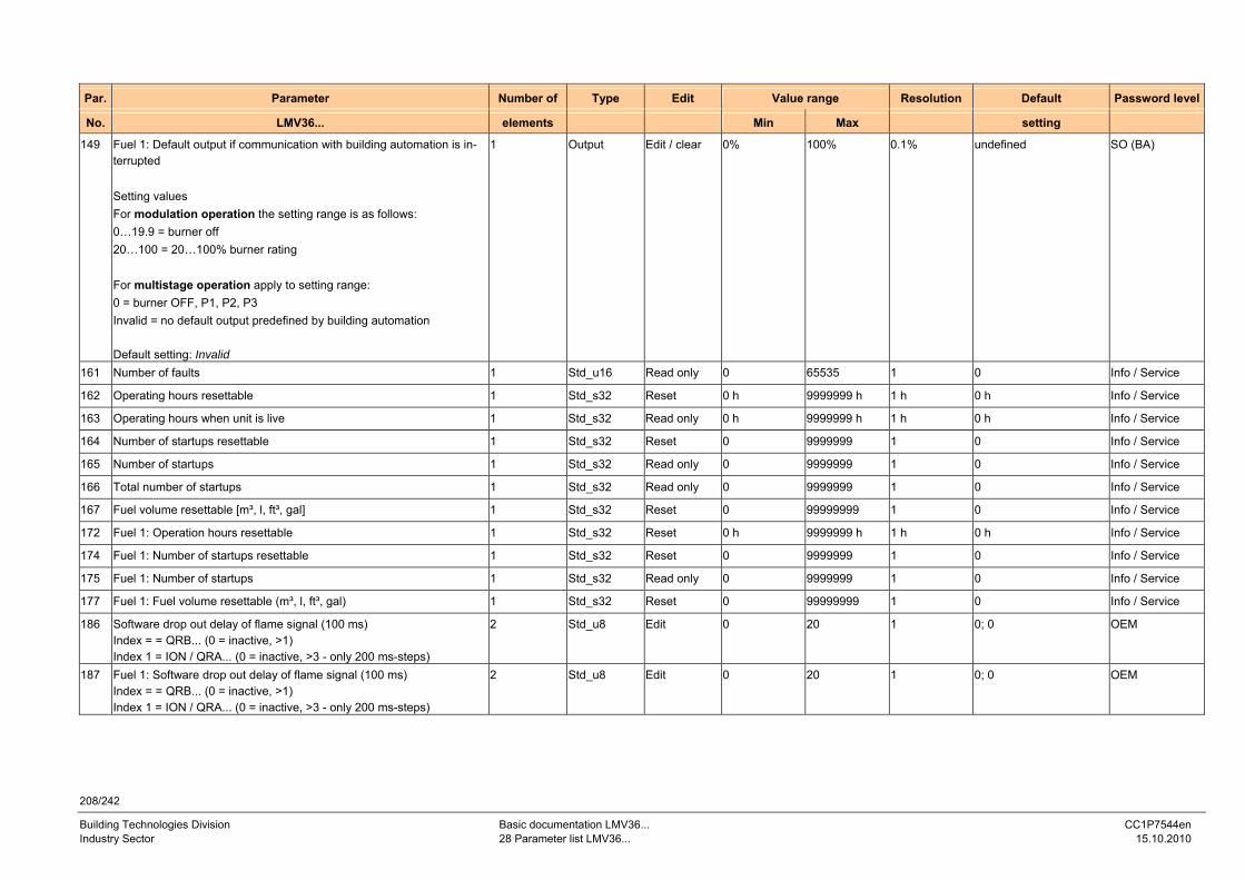
208/242
Building Technologies Division Basic documentation LMV36... CC1P7544en Industry Sector 28 Parameter list LMV36... 15.10.2010
Par. Parameter Number of Type Edit Value range Resolution Default Password level
No. LMV36... elements Min Max setting
149 Fuel 1: Default output if communication with building automation is in-terrupted Setting values For modulation operation the setting range is as follows: 0…19.9 = burner off 20…100 = 20…100% burner rating For multistage operation apply to setting range: 0 = burner OFF, P1, P2, P3 Invalid = no default output predefined by building automation Default setting: Invalid
1 Output Edit / clear 0% 100% 0.1% undefined SO (BA)
161 Number of faults 1 Std_u16 Read only 0 65535 1 0 Info / Service
162 Operating hours resettable 1 Std_s32 Reset 0 h 9999999 h 1 h 0 h Info / Service
163 Operating hours when unit is live 1 Std_s32 Read only 0 h 9999999 h 1 h 0 h Info / Service
164 Number of startups resettable 1 Std_s32 Reset 0 9999999 1 0 Info / Service
165 Number of startups 1 Std_s32 Read only 0 9999999 1 0 Info / Service
166 Total number of startups 1 Std_s32 Read only 0 9999999 1 0 Info / Service
167 Fuel volume resettable [m³, l, ft³, gal] 1 Std_s32 Reset 0 99999999 1 0 Info / Service
172 Fuel 1: Operation hours resettable 1 Std_s32 Reset 0 h 9999999 h 1 h 0 h Info / Service
174 Fuel 1: Number of startups resettable 1 Std_s32 Reset 0 9999999 1 0 Info / Service
175 Fuel 1: Number of startups 1 Std_s32 Read only 0 9999999 1 0 Info / Service
177 Fuel 1: Fuel volume resettable (m³, l, ft³, gal) 1 Std_s32 Reset 0 99999999 1 0 Info / Service
186 Software drop out delay of flame signal (100 ms) Index = = QRB... (0 = inactive, >1) Index 1 = ION / QRA... (0 = inactive, >3 - only 200 ms-steps)
2 Std_u8 Edit 0 20 1 0; 0 OEM
187 Fuel 1: Software drop out delay of flame signal (100 ms) Index = = QRB... (0 = inactive, >1) Index 1 = ION / QRA... (0 = inactive, >3 - only 200 ms-steps)
2 Std_u8 Edit 0 20 1 0; 0 OEM
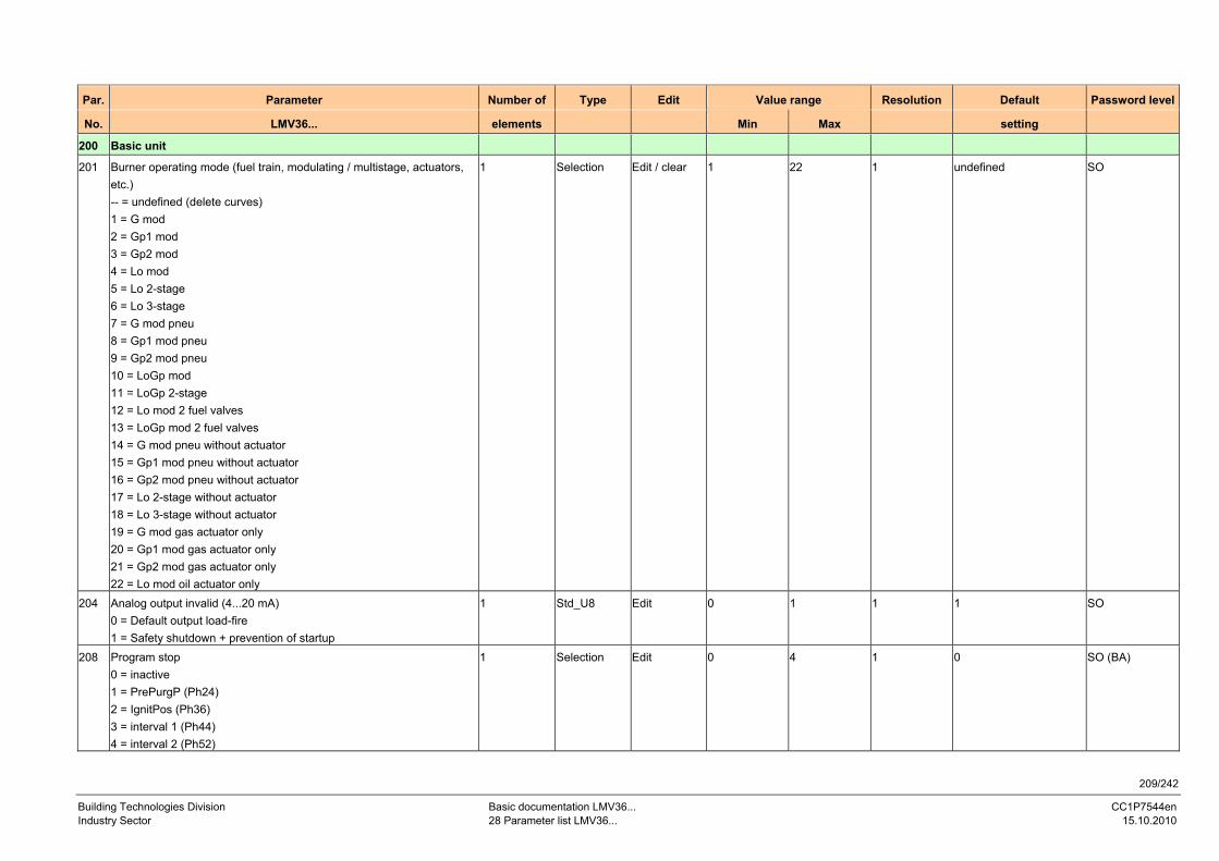
209/242
Building Technologies Division Basic documentation LMV36... CC1P7544en Industry Sector 28 Parameter list LMV36... 15.10.2010
Par. Parameter Number of Type Edit Value range Resolution Default Password level
No. LMV36... elements Min Max setting
200 Basic unit
201 Burner operating mode (fuel train, modulating / multistage, actuators, etc.) -- = undefined (delete curves) 1 = G mod 2 = Gp1 mod 3 = Gp2 mod 4 = Lo mod 5 = Lo 2-stage 6 = Lo 3-stage 7 = G mod pneu 8 = Gp1 mod pneu 9 = Gp2 mod pneu 10 = LoGp mod 11 = LoGp 2-stage 12 = Lo mod 2 fuel valves 13 = LoGp mod 2 fuel valves 14 = G mod pneu without actuator 15 = Gp1 mod pneu without actuator 16 = Gp2 mod pneu without actuator 17 = Lo 2-stage without actuator 18 = Lo 3-stage without actuator 19 = G mod gas actuator only 20 = Gp1 mod gas actuator only 21 = Gp2 mod gas actuator only 22 = Lo mod oil actuator only
1 Selection Edit / clear 1 22 1 undefined SO
204 Analog output invalid (4...20 mA) 0 = Default output load-fire 1 = Safety shutdown + prevention of startup
1 Std_U8 Edit 0 1 1 1 SO
208 Program stop 0 = inactive 1 = PrePurgP (Ph24) 2 = IgnitPos (Ph36) 3 = interval 1 (Ph44) 4 = interval 2 (Ph52)
1 Selection Edit 0 4 1 0 SO (BA)
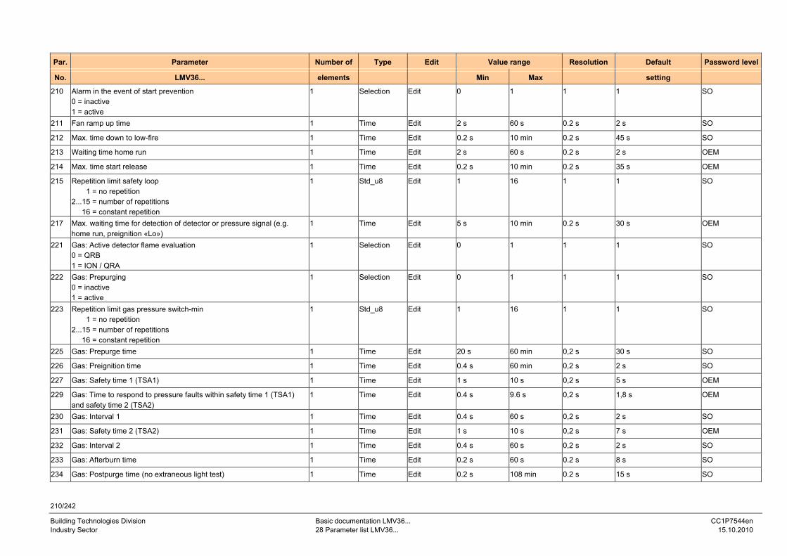
210/242
Building Technologies Division Basic documentation LMV36... CC1P7544en Industry Sector 28 Parameter list LMV36... 15.10.2010
Par. Parameter Number of Type Edit Value range Resolution Default Password level
No. LMV36... elements Min Max setting
210 Alarm in the event of start prevention 0 = inactive 1 = active
1 Selection Edit 0 1 1 1 SO
211 Fan ramp up time 1 Time Edit 2 s 60 s 0.2 s 2 s SO
212 Max. time down to low-fire 1 Time Edit 0.2 s 10 min 0.2 s 45 s SO
213 Waiting time home run 1 Time Edit 2 s 60 s 0.2 s 2 s OEM
214 Max. time start release 1 Time Edit 0.2 s 10 min 0.2 s 35 s OEM
215 Repetition limit safety loop 1 = no repetition 2...15 = number of repetitions 16 = constant repetition
1 Std_u8 Edit 1 16 1 1 SO
217 Max. waiting time for detection of detector or pressure signal (e.g. home run, preignition «Lo»)
1 Time Edit 5 s 10 min 0.2 s 30 s OEM
221 Gas: Active detector flame evaluation 0 = QRB 1 = ION / QRA
1 Selection Edit 0 1 1 1 SO
222 Gas: Prepurging 0 = inactive 1 = active
1 Selection Edit 0 1 1 1 SO
223 Repetition limit gas pressure switch-min 1 = no repetition 2...15 = number of repetitions 16 = constant repetition
1 Std_u8 Edit 1 16 1 1 SO
225 Gas: Prepurge time 1 Time Edit 20 s 60 min 0,2 s 30 s SO
226 Gas: Preignition time 1 Time Edit 0.4 s 60 min 0,2 s 2 s SO
227 Gas: Safety time 1 (TSA1) 1 Time Edit 1 s 10 s 0,2 s 5 s OEM
229 Gas: Time to respond to pressure faults within safety time 1 (TSA1) and safety time 2 (TSA2)
1 Time Edit 0.4 s 9.6 s 0,2 s 1,8 s OEM
230 Gas: Interval 1 1 Time Edit 0.4 s 60 s 0,2 s 2 s SO
231 Gas: Safety time 2 (TSA2) 1 Time Edit 1 s 10 s 0,2 s 7 s OEM
232 Gas: Interval 2 1 Time Edit 0.4 s 60 s 0,2 s 2 s SO
233 Gas: Afterburn time 1 Time Edit 0.2 s 60 s 0.2 s 8 s SO
234 Gas: Postpurge time (no extraneous light test) 1 Time Edit 0.2 s 108 min 0.2 s 15 s SO
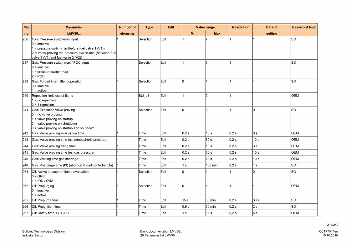
211/242
Building Technologies Division Basic documentation LMV36... CC1P7544en Industry Sector 28 Parameter list LMV36... 15.10.2010
Par. Parameter Number of Type Edit Value range Resolution Default Password level
no. LMV36... elements Min Max setting 236 Gas: Pressure switch-min input
0 = inactive 1 = pressure switch-min (before fuel valve 1 (V1)) 2 = valve proving via pressure switch-min (between fuel valve 1 (V1) and fuel valve 2 (V2))
1 Selection Edit 1 2 1 1 SO
237 Gas: Pressure switch-max / POC input 0 = inactive 1 = pressure switch-max 2 = POC
1 Selection Edit 1 3 1 1 SO
239 Gas. Forced intermittent operation 0 = inactive 1 = active
1 Selection Edit 0 1 1 1 SO
240 Repetition limit loss of flame 1 = no repetition 2 = 1 repetition
1 Std_u8 Edit 1 2 1 1 OEM
241 Gas: Execution valve proving 0 = no valve proving 1 = valve proving on startup 2 = valve proving on shutdown 3 = valve proving on startup and shutdown
1 Selection Edit 0 3 1 0 SO
242 Gas: Valve proving evacuation time 1 Time Edit 0.2 s 10 s 0.2 s 3 s OEM
243 Gas: Valve proving time test atmospheric pressure 1 Time Edit 0.2 s 60 s 0.2 s 10 s OEM
244 Gas: Valve proving filling time 1 Time Edit 0.2 s 10 s 0.2 s 3 s OEM
245 Gas: Valve proving time test gas pressure 1 Time Edit 0.2 s 60 s 0.2 s 10 s OEM
246 Gas: Waiting time gas shortage 1 Time Edit 0.2 s 60 s 0.2 s 10 s OEM
248 Gas: Postpurge time (t3) (abortion if load controller On) 1 Time Edit 1 s 108 min 0.2 s 1 s SO
261 Oil: Active detector of flame evaluation 0 = QRB 1 = ION / QRA
1 Selection Edit 0 1 1 0 SO
262 Oil: Prepurging 0 = inactive 1 = active
1 Selection Edit 0 1 1 1 OEM
265 Oil: Prepurge time 1 Time Edit 15 s 60 min 0.2 s 30 s SO
266 Oil: Preignition time 1 Time Edit 0.6 s 60 min 0,2 s 2 s SO
267 Oil: Safety time 1 (TSA1) 1 Time Edit 1 s 15 s 0,2 s 5 s OEM
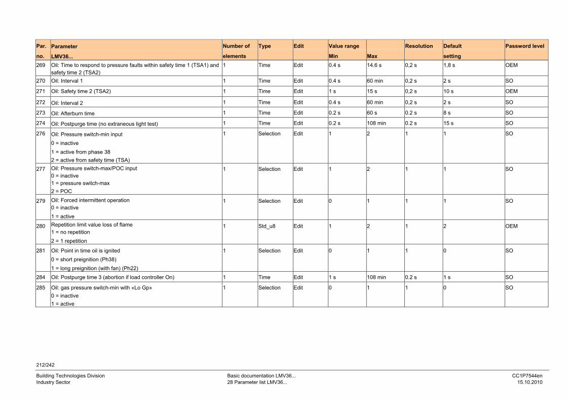
212/242
Building Technologies Division Basic documentation LMV36... CC1P7544en Industry Sector 28 Parameter list LMV36... 15.10.2010
Par. Parameter Number of Type Edit Value range Resolution Default Password level
no. LMV36... elements Min Max setting
269 Oil: Time to respond to pressure faults within safety time 1 (TSA1) and safety time 2 (TSA2)
1 Time Edit 0.4 s 14.6 s 0,2 s 1,8 s OEM
270 Oil: Interval 1 1 Time Edit 0.4 s 60 min 0,2 s 2 s SO
271 Oil: Safety time 2 (TSA2) 1 Time Edit 1 s 15 s 0,2 s 10 s OEM
272 Oil: Interval 2 1 Time Edit 0.4 s 60 min 0,2 s 2 s SO
273 Oil: Afterburn time 1 Time Edit 0.2 s 60 s 0.2 s 8 s SO
274 Oil: Postpurge time (no extraneous light test) 1 Time Edit 0.2 s 108 min 0.2 s 15 s SO
276 Oil: Pressure switch-min input 0 = inactive 1 = active from phase 38 2 = active from safety time (TSA)
1 Selection Edit 1 2 1 1 SO
277 Oil: Pressure switch-max/POC input 0 = inactive 1 = pressure switch-max 2 = POC
1 Selection Edit 1 2 1 1 SO
279 Oil: Forced intermittent operation 0 = inactive 1 = active
1 Selection Edit 0 1 1 1 SO
280 Repetition limit value loss of flame 1 = no repetition 2 = 1 repetition
1 Std_u8 Edit 1 2 1 2 OEM
281 Oil: Point in time oil is ignited 0 = short preignition (Ph38) 1 = long preignition (with fan) (Ph22)
1 Selection Edit 0 1 1 0 SO
284 Oil: Postpurge time 3 (abortion if load controller On) 1 Time Edit 1 s 108 min 0.2 s 1 s SO
285 Oil: gas pressure switch-min with «Lo Gp» 0 = inactive 1 = active
1 Selection Edit 0 1 1 0 SO
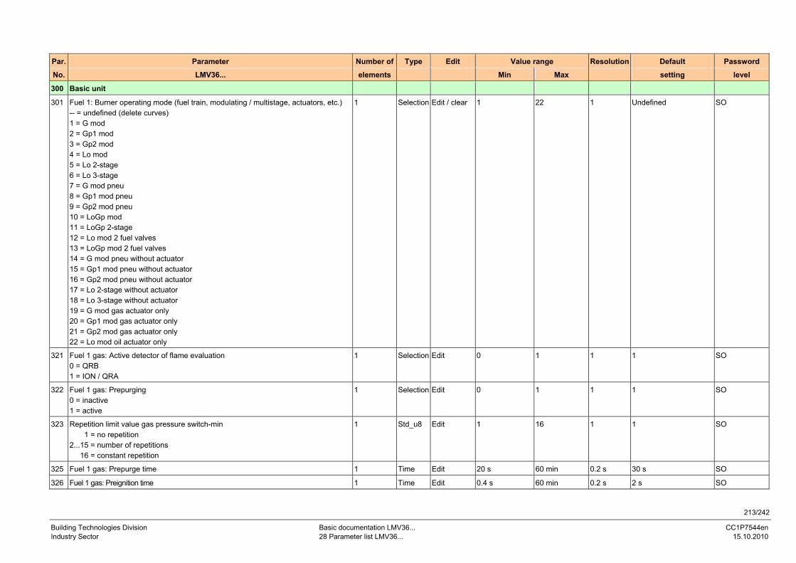
213/242
Building Technologies Division Basic documentation LMV36... CC1P7544en Industry Sector 28 Parameter list LMV36... 15.10.2010
Par. Parameter Number of Type Edit Value range Resolution Default Password
No. LMV36... elements Min Max setting level
300 Basic unit
301 Fuel 1: Burner operating mode (fuel train, modulating / multistage, actuators, etc.) -- = undefined (delete curves) 1 = G mod 2 = Gp1 mod 3 = Gp2 mod 4 = Lo mod 5 = Lo 2-stage 6 = Lo 3-stage 7 = G mod pneu 8 = Gp1 mod pneu 9 = Gp2 mod pneu 10 = LoGp mod 11 = LoGp 2-stage 12 = Lo mod 2 fuel valves 13 = LoGp mod 2 fuel valves 14 = G mod pneu without actuator 15 = Gp1 mod pneu without actuator 16 = Gp2 mod pneu without actuator 17 = Lo 2-stage without actuator 18 = Lo 3-stage without actuator 19 = G mod gas actuator only 20 = Gp1 mod gas actuator only 21 = Gp2 mod gas actuator only 22 = Lo mod oil actuator only
1 Selection Edit / clear 1 22 1 Undefined SO
321 Fuel 1 gas: Active detector of flame evaluation 0 = QRB 1 = ION / QRA
1 Selection Edit 0 1 1 1 SO
322 Fuel 1 gas: Prepurging 0 = inactive 1 = active
1 Selection Edit 0 1 1 1 SO
323 Repetition limit value gas pressure switch-min 1 = no repetition 2...15 = number of repetitions 16 = constant repetition
1 Std_u8 Edit 1 16 1 1 SO
325 Fuel 1 gas: Prepurge time 1 Time Edit 20 s 60 min 0.2 s 30 s SO
326 Fuel 1 gas: Preignition time 1 Time Edit 0.4 s 60 min 0.2 s 2 s SO
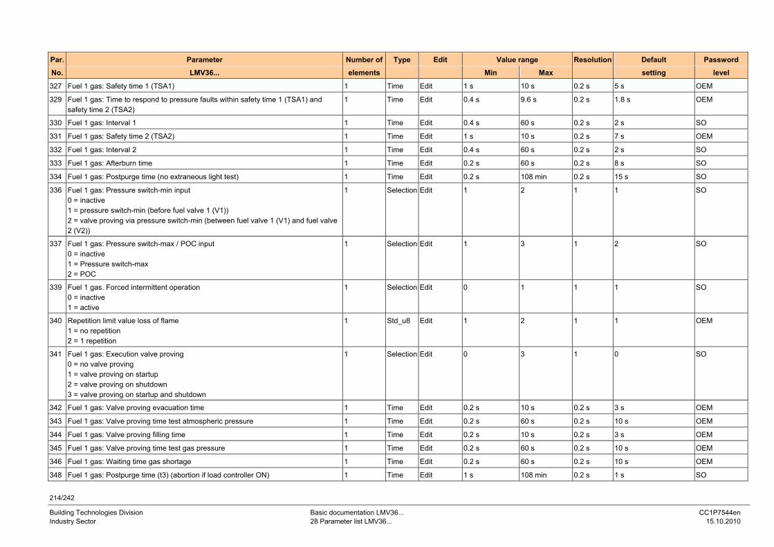
214/242
Building Technologies Division Basic documentation LMV36... CC1P7544en Industry Sector 28 Parameter list LMV36... 15.10.2010
Par. Parameter Number of Type Edit Value range Resolution Default Password
No. LMV36... elements Min Max setting level
327 Fuel 1 gas: Safety time 1 (TSA1) 1 Time Edit 1 s 10 s 0.2 s 5 s OEM
329 Fuel 1 gas: Time to respond to pressure faults within safety time 1 (TSA1) and safety time 2 (TSA2)
1 Time Edit 0.4 s 9.6 s 0.2 s 1.8 s OEM
330 Fuel 1 gas: Interval 1 1 Time Edit 0.4 s 60 s 0.2 s 2 s SO
331 Fuel 1 gas: Safety time 2 (TSA2) 1 Time Edit 1 s 10 s 0.2 s 7 s OEM
332 Fuel 1 gas: Interval 2 1 Time Edit 0.4 s 60 s 0.2 s 2 s SO
333 Fuel 1 gas: Afterburn time 1 Time Edit 0.2 s 60 s 0.2 s 8 s SO
334 Fuel 1 gas: Postpurge time (no extraneous light test) 1 Time Edit 0.2 s 108 min 0.2 s 15 s SO
336 Fuel 1 gas: Pressure switch-min input 0 = inactive 1 = pressure switch-min (before fuel valve 1 (V1)) 2 = valve proving via pressure switch-min (between fuel valve 1 (V1) and fuel valve 2 (V2))
1 Selection Edit 1 2 1 1 SO
337 Fuel 1 gas: Pressure switch-max / POC input 0 = inactive 1 = Pressure switch-max 2 = POC
1 Selection Edit 1 3 1 2 SO
339 Fuel 1 gas. Forced intermittent operation 0 = inactive 1 = active
1 Selection Edit 0 1 1 1 SO
340 Repetition limit value loss of flame 1 = no repetition 2 = 1 repetition
1 Std_u8 Edit 1 2 1 1 OEM
341 Fuel 1 gas: Execution valve proving 0 = no valve proving 1 = valve proving on startup 2 = valve proving on shutdown 3 = valve proving on startup and shutdown
1 Selection Edit 0 3 1 0 SO
342 Fuel 1 gas: Valve proving evacuation time 1 Time Edit 0.2 s 10 s 0.2 s 3 s OEM
343 Fuel 1 gas: Valve proving time test atmospheric pressure 1 Time Edit 0.2 s 60 s 0.2 s 10 s OEM
344 Fuel 1 gas: Valve proving filling time 1 Time Edit 0.2 s 10 s 0.2 s 3 s OEM
345 Fuel 1 gas: Valve proving time test gas pressure 1 Time Edit 0.2 s 60 s 0.2 s 10 s OEM
346 Fuel 1 gas: Waiting time gas shortage 1 Time Edit 0.2 s 60 s 0.2 s 10 s OEM
348 Fuel 1 gas: Postpurge time (t3) (abortion if load controller ON) 1 Time Edit 1 s 108 min 0.2 s 1 s SO
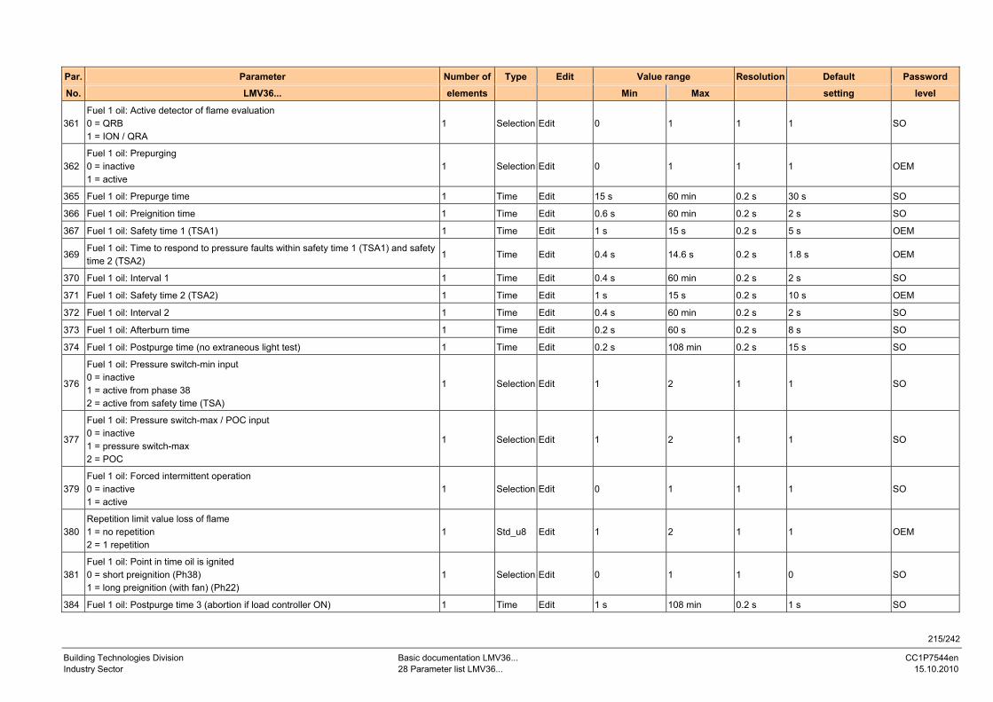
215/242
Building Technologies Division Basic documentation LMV36... CC1P7544en Industry Sector 28 Parameter list LMV36... 15.10.2010
Par. Parameter Number of Type Edit Value range Resolution Default Password
No. LMV36... elements Min Max setting level
361 Fuel 1 oil: Active detector of flame evaluation 0 = QRB 1 = ION / QRA
1 Selection Edit 0 1 1 1 SO
362 Fuel 1 oil: Prepurging 0 = inactive 1 = active
1 Selection Edit 0 1 1 1 OEM
365 Fuel 1 oil: Prepurge time 1 Time Edit 15 s 60 min 0.2 s 30 s SO
366 Fuel 1 oil: Preignition time 1 Time Edit 0.6 s 60 min 0.2 s 2 s SO
367 Fuel 1 oil: Safety time 1 (TSA1) 1 Time Edit 1 s 15 s 0.2 s 5 s OEM
369 Fuel 1 oil: Time to respond to pressure faults within safety time 1 (TSA1) and safety time 2 (TSA2)
1 Time Edit 0.4 s 14.6 s 0.2 s 1.8 s OEM
370 Fuel 1 oil: Interval 1 1 Time Edit 0.4 s 60 min 0.2 s 2 s SO
371 Fuel 1 oil: Safety time 2 (TSA2) 1 Time Edit 1 s 15 s 0.2 s 10 s OEM
372 Fuel 1 oil: Interval 2 1 Time Edit 0.4 s 60 min 0.2 s 2 s SO
373 Fuel 1 oil: Afterburn time 1 Time Edit 0.2 s 60 s 0.2 s 8 s SO
374 Fuel 1 oil: Postpurge time (no extraneous light test) 1 Time Edit 0.2 s 108 min 0.2 s 15 s SO
376
Fuel 1 oil: Pressure switch-min input 0 = inactive 1 = active from phase 38 2 = active from safety time (TSA)
1 Selection Edit 1 2 1 1 SO
377
Fuel 1 oil: Pressure switch-max / POC input 0 = inactive 1 = pressure switch-max 2 = POC
1 Selection Edit 1 2 1 1 SO
379 Fuel 1 oil: Forced intermittent operation 0 = inactive 1 = active
1 Selection Edit 0 1 1 1 SO
380 Repetition limit value loss of flame 1 = no repetition 2 = 1 repetition
1 Std_u8 Edit 1 2 1 1 OEM
381 Fuel 1 oil: Point in time oil is ignited 0 = short preignition (Ph38) 1 = long preignition (with fan) (Ph22)
1 Selection Edit 0 1 1 0 SO
384 Fuel 1 oil: Postpurge time 3 (abortion if load controller ON) 1 Time Edit 1 s 108 min 0.2 s 1 s SO
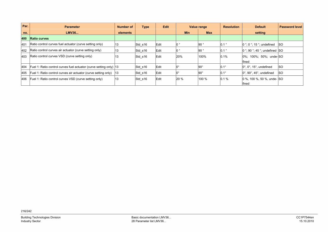
216/242
Building Technologies Division Basic documentation LMV36... CC1P7544en Industry Sector 28 Parameter list LMV36... 15.10.2010
Par. Parameter Number of Type Edit Value range Resolution Default Password level
no. LMV36... elements Min Max setting
400 Ratio curves
401 Ratio control curves fuel actuator (curve setting only) 13 Std_s16 Edit 0 ° 90 ° 0.1 ° 0 °; 0 °; 15 °; undefined SO
402 Ratio control curves air actuator (curve setting only) 13 Std_s16 Edit 0 ° 90 ° 0.1 ° 0 °; 90 °; 45 °; undefined SO
403 Ratio control curves VSD (curve setting only) 13 Std_s16 Edit 20% 100% 0.1% 0%; 100%; 50%; unde-fined
SO
404 Fuel 1: Ratio control curves fuel actuator (curve setting only) 13 Std_s16 Edit 0° 90° 0.1° 0°, 0°, 15°, undefined SO
405 Fuel 1: Ratio control curves air actuator (curve setting only) 13 Std_s16 Edit 0° 90° 0.1° 0°, 90°, 45°, undefined SO
406 Fuel 1: Ratio control curves VSD (curve setting only) 13 Std_s16 Edit 20 % 100 % 0.1 % 0 %, 100 %, 50 %, unde-fined
SO
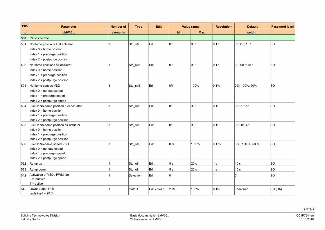
217/242
Building Technologies Division Basic documentation LMV36... CC1P7544en Industry Sector 28 Parameter list LMV36... 15.10.2010
Par. Parameter Number of Type Edit Value range Resolution Default Password level
no. LMV36... elements Min Max setting
500 Ratio control
501 No-flame positions fuel actuator Index 0 = home position Index 1 = prepurge position Index 2 = postpurge position
3 Std_s16 Edit 0 ° 90 ° 0.1 ° 0 °; 0 °; 15 ° SO
502 No-flame positions air actuator Index 0 = home position Index 1 = prepurge position Index 2 = postpurge position
3 Std_s16 Edit 0 ° 90 ° 0.1 ° 0 °; 90 °; 45 ° SO
503 No-flame speeds VSD Index 0 = no-load speed Index 1 = prepurge speed Index 2 = postpurge speed
3 Std_s16 Edit 0% 100% 0.1% 0%; 100%; 50% SO
504 Fuel 1: No-flame position fuel actuator Index 0 = home position Index 1 = prepurge position Index 2 = postpurge position
3 Std_s16 Edit 0° 90° 0.1° 0°, 0°, 15° SO
505 Fuel 1: No-flame position air actuator Index 0 = home position Index 1 = prepurge position Index 2 = postpurge position
3 Std_s16 Edit 0° 90° 0.1° 0°, 90°, 45° SO
506 Fuel 1: No-flame speed VSD Index 0 = no-load speed Index 1 = prepurge speed Index 2 = postpurge speed
3 Std_s16 Edit 0 % 100 % 0.1 % 0 %, 100 %, 50 % SO
522 Ramp up 1 Std_u8 Edit 5 s 20 s 1 s 10 s SO
523 Ramp down 1 Std_u8 Edit 5 s 20 s 1 s 10 s SO
542 Activation of VSD / PWM fan 0 = inactive 1 = active
1 Selection Edit 0 1 1 0 SO
545 Lower output limit undefined = 20 %
1 Output Edit / clear 20% 100% 0.1% undefined SO (BA)
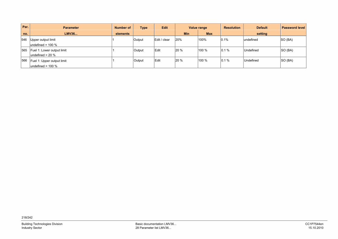
218/242
Building Technologies Division Basic documentation LMV36... CC1P7544en Industry Sector 28 Parameter list LMV36... 15.10.2010
Par. Parameter Number of Type Edit Value range Resolution Default Password level
no. LMV36... elements Min Max setting
546 Upper output limit undefined = 100 %
1 Output Edit / clear 20% 100% 0.1% undefined SO (BA)
565 Fuel 1: Lower output limit undefined = 20 %
1 Output Edit 20 % 100 % 0.1 % Undefined SO (BA)
566 Fuel 1: Upper output limit undefined = 100 %
1 Output Edit 20 % 100 % 0.1 % Undefined SO (BA)
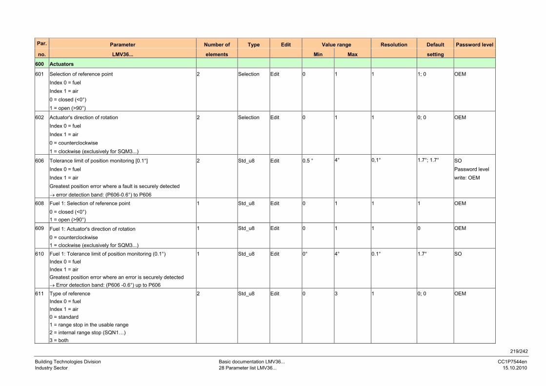
219/242
Building Technologies Division Basic documentation LMV36... CC1P7544en Industry Sector 28 Parameter list LMV36... 15.10.2010
Par. Parameter Number of Type Edit Value range Resolution Default Password level
no. LMV36... elements Min Max setting
600 Actuators
601 Selection of reference point Index 0 = fuel Index 1 = air 0 = closed (<0°) 1 = open (>90°)
2 Selection Edit 0 1 1 1; 0 OEM
602 Actuator's direction of rotation Index 0 = fuel Index 1 = air 0 = counterclockwise 1 = clockwise (exclusively for SQM3...)
2 Selection Edit 0 1 1 0; 0 OEM
606 Tolerance limit of position monitoring [0.1°] Index 0 = fuel Index 1 = air Greatest position error where a fault is securely detected → error detection band: (P606-0.6°) to P606
2 Std_u8 Edit 0.5 ° 4° 0,1° 1.7°; 1.7° SO Password level write: OEM
608 Fuel 1: Selection of reference point 0 = closed (<0°) 1 = open (>90°)
1 Std_u8 Edit 0 1 1 1 OEM
609 Fuel 1: Actuator's direction of rotation 0 = counterclockwise 1 = clockwise (exclusively for SQM3...)
1 Std_u8 Edit 0 1 1 0 OEM
610 Fuel 1: Tolerance limit of position monitoring (0.1°) Index 0 = fuel Index 1 = air Greatest position error where an error is securely detected → Error detection band: (P606 -0.6°) up to P606
1 Std_u8 Edit 0° 4° 0.1° 1.7° SO
611 Type of reference Index 0 = fuel Index 1 = air 0 = standard 1 = range stop in the usable range 2 = internal range stop (SQN1…) 3 = both
2 Std_u8 Edit 0 3 1 0; 0 OEM
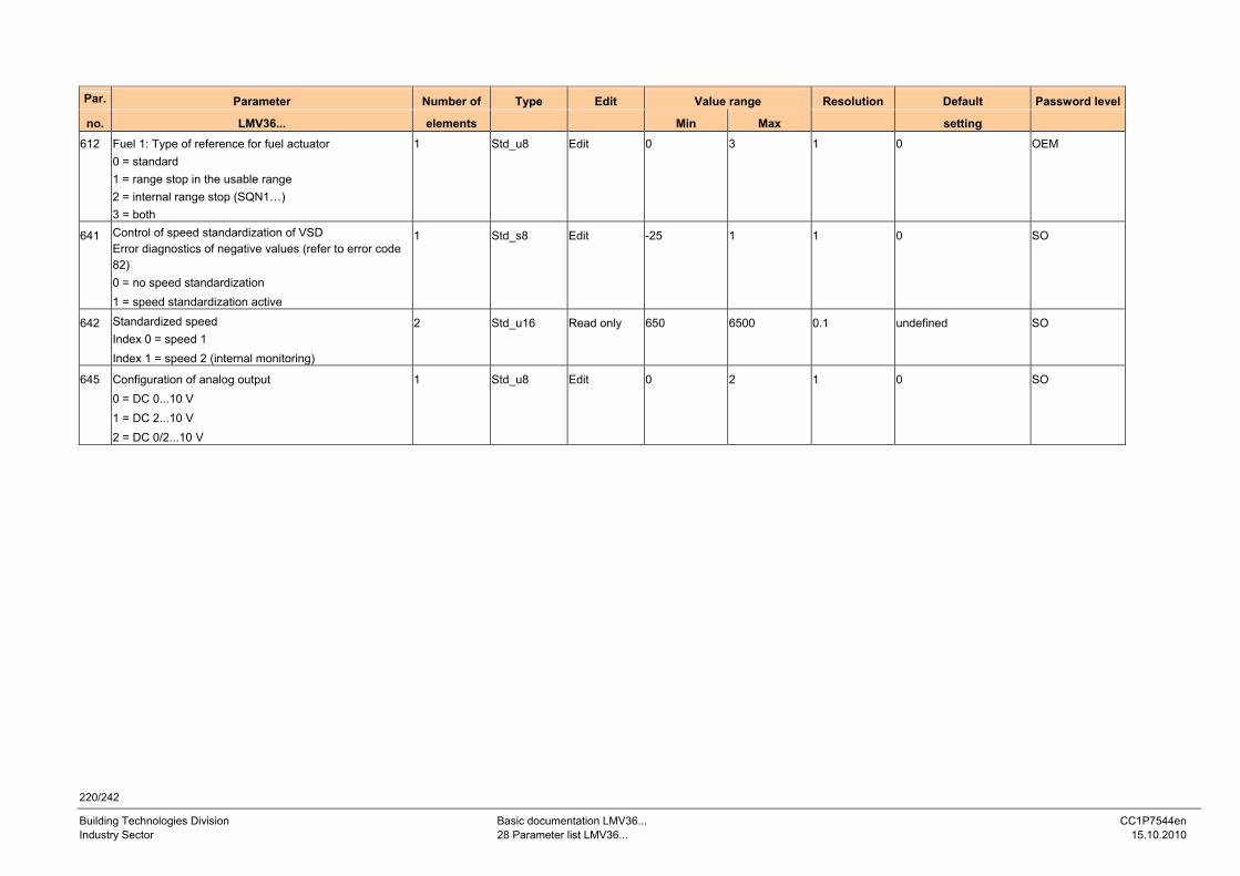
220/242
Building Technologies Division Basic documentation LMV36... CC1P7544en Industry Sector 28 Parameter list LMV36... 15.10.2010
Par. Parameter Number of Type Edit Value range Resolution Default Password level
no. LMV36... elements Min Max setting 612 Fuel 1: Type of reference for fuel actuator
0 = standard 1 = range stop in the usable range 2 = internal range stop (SQN1…) 3 = both
1 Std_u8 Edit 0 3 1 0 OEM
641 Control of speed standardization of VSD Error diagnostics of negative values (refer to error code 82) 0 = no speed standardization 1 = speed standardization active
1 Std_s8 Edit -25 1 1 0 SO
642 Standardized speed Index 0 = speed 1 Index 1 = speed 2 (internal monitoring)
2 Std_u16 Read only 650 6500 0.1 undefined SO
645 Configuration of analog output 0 = DC 0...10 V 1 = DC 2...10 V 2 = DC 0/2...10 V
1 Std_u8 Edit 0 2 1 0 SO
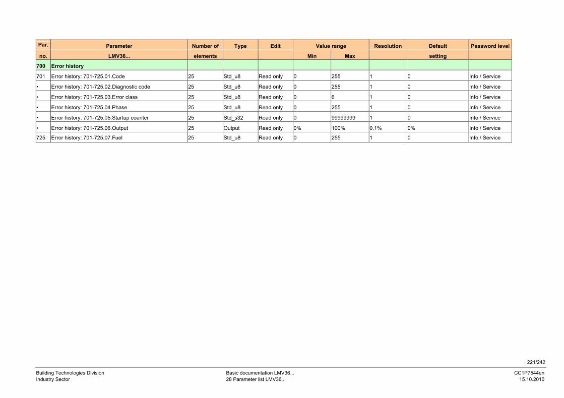
221/242
Building Technologies Division Basic documentation LMV36... CC1P7544en Industry Sector 28 Parameter list LMV36... 15.10.2010
Par. Parameter Number of Type Edit Value range Resolution Default Password level
no. LMV36... elements Min Max setting
700 Error history
701 Error history: 701-725.01.Code 25 Std_u8 Read only 0 255 1 0 Info / Service
• Error history: 701-725.02.Diagnostic code 25 Std_u8 Read only 0 255 1 0 Info / Service
• Error history: 701-725.03.Error class 25 Std_u8 Read only 0 6 1 0 Info / Service
• Error history: 701-725.04.Phase 25 Std_u8 Read only 0 255 1 0 Info / Service
• Error history: 701-725.05.Startup counter 25 Std_s32 Read only 0 99999999 1 0 Info / Service
• Error history: 701-725.06.Output 25 Output Read only 0% 100% 0.1% 0% Info / Service
725 Error history: 701-725.07.Fuel 25 Std_u8 Read only 0 255 1 0 Info / Service
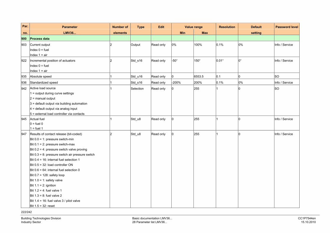
222/242
Building Technologies Division Basic documentation LMV36... CC1P7544en Industry Sector 28 Parameter list LMV36... 15.10.2010
Par. Parameter Number of Type Edit Value range Resolution Default Password level
no. LMV36... elements Min Max setting
900 Process data
903 Current output Index 0 = fuel Index 1 = air
2 Output Read only 0% 100% 0.1% 0% Info / Service
922 Incremental position of actuators Index 0 = fuel Index 1 = air
2 Std_s16 Read only -50° 150° 0.01° 0° Info / Service
935 Absolute speed 1 Std_u16 Read only 0 6553.5 0.1 0 SO
936 Standardized speed 1 Std_s16 Read only -200% 200% 0.1% 0% Info / Service
942 Active load source 1 = output during curve settings 2 = manual output 3 = default output via building automation 4 = default output via analog input 5 = external load controller via contacts
1 Selection Read only 0 255 1 0 SO
945 Actual fuel 0 = fuel 0 1 = fuel 1
1 Std_u8 Read only 0 255 1 0 Info / Service
947 Results of contact release (bit-coded) Bit 0.0 = 1: pressure switch-min Bit 0.1 = 2: pressure switch-max Bit 0.2 = 4: pressure switch valve proving Bit 0.3 = 8: pressure switch air pressure switch Bit 0.4 = 16: internal fuel selection 1 Bit 0.5 = 32: load controller ON Bit 0.6 = 64: internal fuel selection 0 Bit 0.7 = 128: safety loop Bit 1.0 = 1: safety valve Bit 1.1 = 2: ignition Bit 1.2 = 4: fuel valve 1 Bit 1.3 = 8: fuel valve 2 Bit 1.4 = 16: fuel valve 3 / pilot valve Bit 1.5 = 32: reset
2 Std_u8 Read only 0 255 1 0 Info / Service
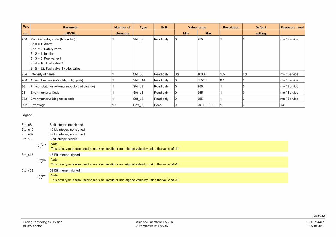
223/242
Building Technologies Division Basic documentation LMV36... CC1P7544en Industry Sector 28 Parameter list LMV36... 15.10.2010
Par. Parameter Number of Type Edit Value range Resolution Default Password level
no. LMV36... elements Min Max setting
950 Required relay state (bit-coded) Bit 0 = 1: Alarm Bit 1 = 2: Safety valve Bit 2 = 4: Ignition Bit 3 = 8: Fuel valve 1 Bit 4 = 16: Fuel valve 2 Bit 5 = 32: Fuel valve 3 / pilot valve
1 Std_u8 Read only 0 255 1 0 Info / Service
954 Intensity of flame 1 Std_u8 Read only 0% 100% 1% 0% Info / Service
960 Actual flow rate (m³/h, l/h, ft³/h, gal/h) 1 Std_u16 Read only 0 6553.5 0.1 0 Info / Service
961 Phase (state for external module and display) 1 Std_u8 Read only 0 255 1 0 Info / Service
981 Error memory: Code 1 Std_u8 Read only 0 255 1 0 Info / Service
982 Error memory: Diagnostic code 1 Std_u8 Read only 0 255 1 0 Info / Service
992 Error flags 10 Hex_32 Reset 0 0xFFFFFFFF 1 0 SO
Legend Std_u8 8 bit integer, not signed Std_u16 16 bit integer, not signed Std_u32 32 bit integer, not signed Std_s8 8 bit integer, signed
Note This data type is also used to mark an invalid or non-signed value by using the value of -1!
Std_s16 16 Bit integer, signed
Note This data type is also used to mark an invalid or non-signed value by using the value of -1!
Std_s32 32 Bit integer, signed
Note This data type is also used to mark an invalid or non-signed value by using the value of -1!
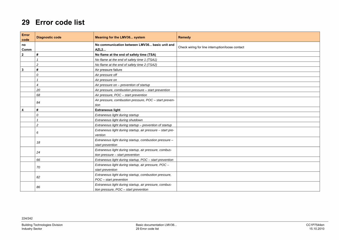
224/242
Building Technologies Division Basic documentation LMV36... CC1P7544en Industry Sector 29 Error code list 15.10.2010
29 Error code list Error code
Diagnostic code Meaning for the LMV36... system Remedy
no Comm
No communication between LMV36... basic unit and AZL2...
Check wiring for line interruption/loose contact
2 # No flame at the end of safety time (TSA) 1 No flame at the end of safety time 1 (TSA1) 2 No flame at the end of safety time 2 (TSA2) 3 # Air pressure failure 0 Air pressure off 1 Air pressure on 4 Air pressure on – prevention of startup 20 Air pressure, combustion pressure – start prevention 68 Air pressure, POC – start prevention
84 Air pressure, combustion pressure, POC – start preven-tion
4 # Extraneous light 0 Extraneous light during startup 1 Extraneous light during shutdown 2 Extraneous light during startup – prevention of startup
6 Extraneous light during startup, air pressure – start pre-vention
18 Extraneous light during startup, combustion pressure – start prevention
24 Extraneous light during startup, air pressure, combus-tion pressure – start prevention
66 Extraneous light during startup, POC – start prevention
70 Extraneous light during startup, air pressure, POC – start prevention
82 Extraneous light during startup, combustion pressure, POC – start prevention
86 Extraneous light during startup, air pressure, combus-tion pressure, POC – start prevention

225/242
Building Technologies Division Basic documentation LMV36... CC1P7544en Industry Sector 29 Error code list 15.10.2010
Error code
Diagnostic code Meaning for the LMV36... system Remedy
7 # Loss of flame 0 Loss of flame
3...255 Loss of flame due to TÜV test (loss-of-flame test) Diagnostics corresponds to the period of time from shutdown of fuel valves to the detection of loss of flame (resolution 0.2 s → Value 5 = 1 s)
12 # Valve proving
0 Fuel valve 1 (V1) leaking Check to see if valve on the gas side is leaking Check to see if there is a line interruption
1 Fuel valve 2 (V2) leaking Check to see if valve on the burner side is leaking Check to see if pressure switch for the valve proving is closed when gas pressure is present Check wiring to see if there is a short-circuit
2 Valve proving not possible Valve proving activated, but DWmin selected as input function for X9-04 (check parameters 238 and 241)
3 Valve proving not possible Valve proving activated, but no input assigned (check parameters 236 and 237) 4 Valve proving not possible Valve proving activated, but 2 inputs assigned (set parameter 237 to DWmax or POC) 5 Valve proving not possible Valve proving activated, but 2 inputs assigned (check parameters 236 and 237) 14 # POC 0 POC open Check to see if the valve’s closing contact is closed
1 POC closed Check wiring Check to see if the valve’s closing contact opens when valve is controlled
64 POC open – prevention of startup Check wiring to see if there is a line interruption. Check to see if the valve’s closing contact is closed
19 80 Combustion pressure, POC – start prevention Check to see if pressure switch has closed with no combustion pressure present Check wiring for short-circuit
20 # Pressure switch-min (Pmin) 0 No minimum gas / oil pressure Check wiring for line interruption 1 Gas shortage / prevention of startup Check wiring for line interruption
21 0 Pressure switch-max (Pmax): Max. gas / oil pressure exceeded
Check wiring to see if there is a line interruption. POC: Check to see if the valve’s closing contact is closed.
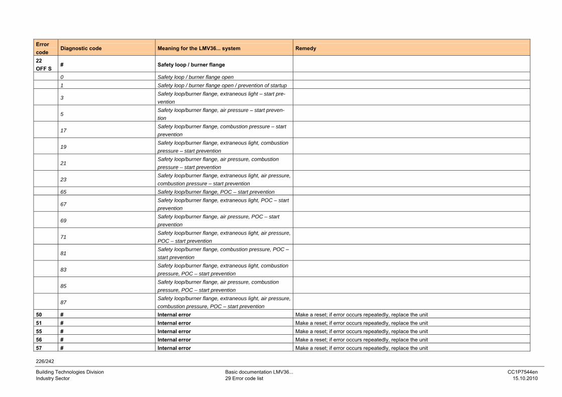
226/242
Building Technologies Division Basic documentation LMV36... CC1P7544en Industry Sector 29 Error code list 15.10.2010
Error code
Diagnostic code Meaning for the LMV36... system Remedy
22 OFF S
# Safety loop / burner flange
0 Safety loop / burner flange open 1 Safety loop / burner flange open / prevention of startup
3 Safety loop/burner flange, extraneous light – start pre-vention
5 Safety loop/burner flange, air pressure – start preven-tion
17 Safety loop/burner flange, combustion pressure – start prevention
19 Safety loop/burner flange, extraneous light, combustion pressure – start prevention
21 Safety loop/burner flange, air pressure, combustion pressure – start prevention
23 Safety loop/burner flange, extraneous light, air pressure, combustion pressure – start prevention
65 Safety loop/burner flange, POC – start prevention
67 Safety loop/burner flange, extraneous light, POC – start prevention
69 Safety loop/burner flange, air pressure, POC – start prevention
71 Safety loop/burner flange, extraneous light, air pressure, POC – start prevention
81 Safety loop/burner flange, combustion pressure, POC – start prevention
83 Safety loop/burner flange, extraneous light, combustion pressure, POC – start prevention
85 Safety loop/burner flange, air pressure, combustion pressure, POC – start prevention
87 Safety loop/burner flange, extraneous light, air pressure, combustion pressure, POC – start prevention
50 # Internal error Make a reset; if error occurs repeatedly, replace the unit 51 # Internal error Make a reset; if error occurs repeatedly, replace the unit 55 # Internal error Make a reset; if error occurs repeatedly, replace the unit 56 # Internal error Make a reset; if error occurs repeatedly, replace the unit 57 # Internal error Make a reset; if error occurs repeatedly, replace the unit
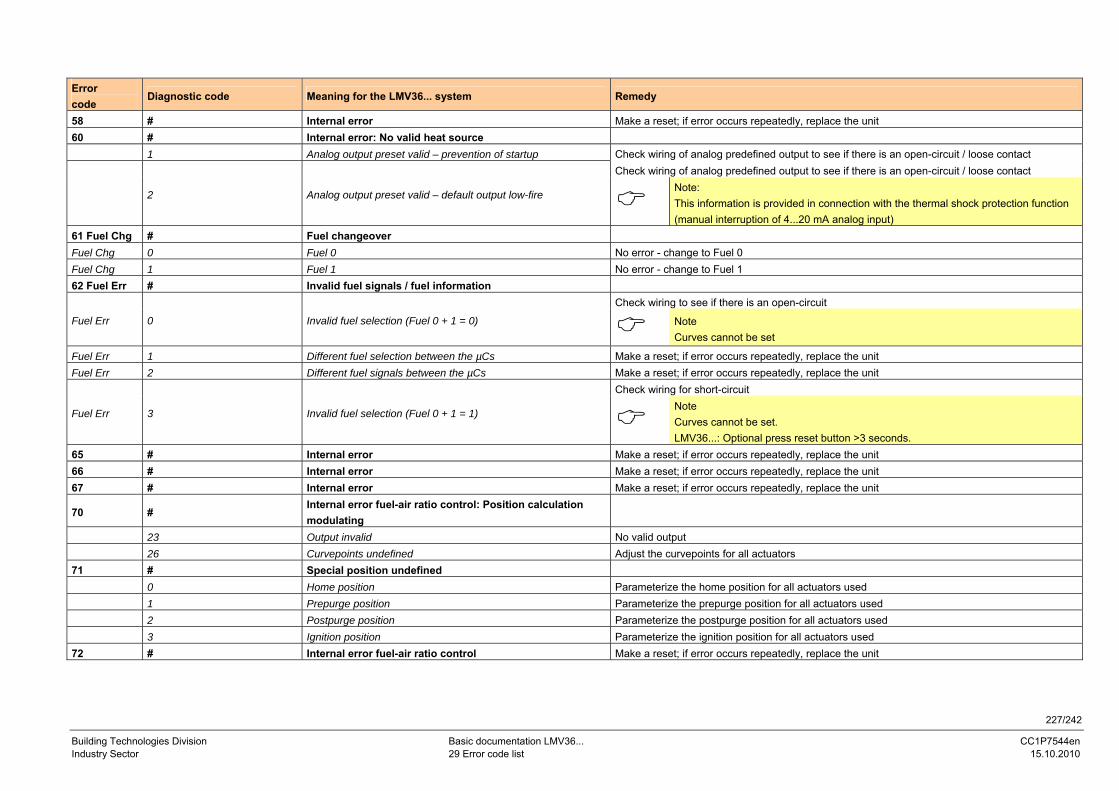
227/242
Building Technologies Division Basic documentation LMV36... CC1P7544en Industry Sector 29 Error code list 15.10.2010
Error code
Diagnostic code Meaning for the LMV36... system Remedy
58 # Internal error Make a reset; if error occurs repeatedly, replace the unit 60 # Internal error: No valid heat source 1 Analog output preset valid – prevention of startup Check wiring of analog predefined output to see if there is an open-circuit / loose contact
Check wiring of analog predefined output to see if there is an open-circuit / loose contact
2 Analog output preset valid – default output low-fire Note: This information is provided in connection with the thermal shock protection function (manual interruption of 4...20 mA analog input)
61 Fuel Chg # Fuel changeover Fuel Chg 0 Fuel 0 No error - change to Fuel 0 Fuel Chg 1 Fuel 1 No error - change to Fuel 1 62 Fuel Err # Invalid fuel signals / fuel information
Check wiring to see if there is an open-circuit
Fuel Err 0 Invalid fuel selection (Fuel 0 + 1 = 0)
Note Curves cannot be set
Fuel Err 1 Different fuel selection between the µCs Make a reset; if error occurs repeatedly, replace the unit Fuel Err 2 Different fuel signals between the µCs Make a reset; if error occurs repeatedly, replace the unit
Check wiring for short-circuit
Fuel Err 3 Invalid fuel selection (Fuel 0 + 1 = 1)
Note Curves cannot be set. LMV36...: Optional press reset button >3 seconds.
65 # Internal error Make a reset; if error occurs repeatedly, replace the unit 66 # Internal error Make a reset; if error occurs repeatedly, replace the unit 67 # Internal error Make a reset; if error occurs repeatedly, replace the unit
70 # Internal error fuel-air ratio control: Position calculation modulating
23 Output invalid No valid output 26 Curvepoints undefined Adjust the curvepoints for all actuators 71 # Special position undefined 0 Home position Parameterize the home position for all actuators used 1 Prepurge position Parameterize the prepurge position for all actuators used 2 Postpurge position Parameterize the postpurge position for all actuators used 3 Ignition position Parameterize the ignition position for all actuators used 72 # Internal error fuel-air ratio control Make a reset; if error occurs repeatedly, replace the unit
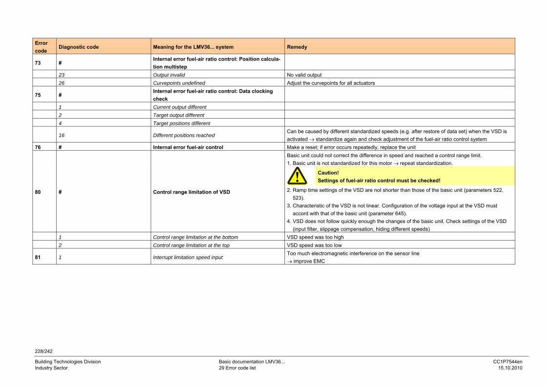
228/242
Building Technologies Division Basic documentation LMV36... CC1P7544en Industry Sector 29 Error code list 15.10.2010
Error code
Diagnostic code Meaning for the LMV36... system Remedy
73 # Internal error fuel-air ratio control: Position calcula-tion multistep
23 Output invalid No valid output 26 Curvepoints undefined Adjust the curvepoints for all actuators
75 # Internal error fuel-air ratio control: Data clocking check
1 Current output different 2 Target output different 4 Target positions different
16 Different positions reached Can be caused by different standardized speeds (e.g. after restore of data set) when the VSD is activated → standardize again and check adjustment of the fuel-air ratio control system
76 # Internal error fuel-air control Make a reset; if error occurs repeatedly, replace the unit Basic unit could not correct the difference in speed and reached a control range limit. 1. Basic unit is not standardized for this motor → repeat standardization.
Caution! Settings of fuel-air ratio control must be checked!
80 # Control range limitation of VSD 2. Ramp time settings of the VSD are not shorter than those of the basic unit (parameters 522, 523). 3. Characteristic of the VSD is not linear. Configuration of the voltage input at the VSD must accord with that of the basic unit (parameter 645). 4. VSD does not follow quickly enough the changes of the basic unit. Check settings of the VSD (input filter, slippage compensation, hiding different speeds)
1 Control range limitation at the bottom VSD speed was too high 2 Control range limitation at the top VSD speed was too low
81 1 Interrupt limitation speed input Too much electromagnetic interference on the sensor line → improve EMC
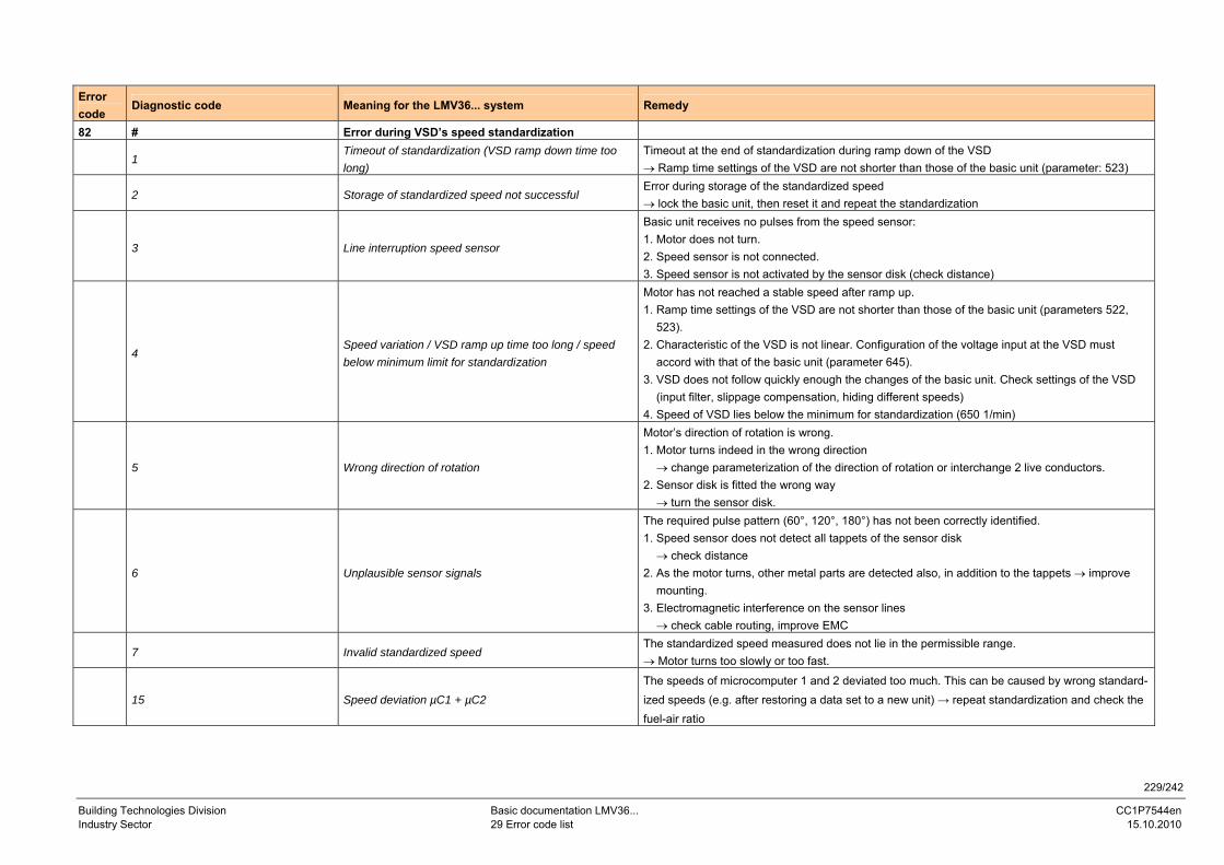
229/242
Building Technologies Division Basic documentation LMV36... CC1P7544en Industry Sector 29 Error code list 15.10.2010
Error code
Diagnostic code Meaning for the LMV36... system Remedy
82 # Error during VSD’s speed standardization
1 Timeout of standardization (VSD ramp down time too long)
Timeout at the end of standardization during ramp down of the VSD → Ramp time settings of the VSD are not shorter than those of the basic unit (parameter: 523)
2 Storage of standardized speed not successful Error during storage of the standardized speed → lock the basic unit, then reset it and repeat the standardization
3 Line interruption speed sensor
Basic unit receives no pulses from the speed sensor: 1. Motor does not turn. 2. Speed sensor is not connected. 3. Speed sensor is not activated by the sensor disk (check distance)
4 Speed variation / VSD ramp up time too long / speed below minimum limit for standardization
Motor has not reached a stable speed after ramp up. 1. Ramp time settings of the VSD are not shorter than those of the basic unit (parameters 522, 523). 2. Characteristic of the VSD is not linear. Configuration of the voltage input at the VSD must accord with that of the basic unit (parameter 645). 3. VSD does not follow quickly enough the changes of the basic unit. Check settings of the VSD (input filter, slippage compensation, hiding different speeds) 4. Speed of VSD lies below the minimum for standardization (650 1/min)
5 Wrong direction of rotation
Motor’s direction of rotation is wrong. 1. Motor turns indeed in the wrong direction → change parameterization of the direction of rotation or interchange 2 live conductors. 2. Sensor disk is fitted the wrong way → turn the sensor disk.
6 Unplausible sensor signals
The required pulse pattern (60°, 120°, 180°) has not been correctly identified. 1. Speed sensor does not detect all tappets of the sensor disk → check distance 2. As the motor turns, other metal parts are detected also, in addition to the tappets → improve mounting. 3. Electromagnetic interference on the sensor lines → check cable routing, improve EMC
7 Invalid standardized speed The standardized speed measured does not lie in the permissible range. → Motor turns too slowly or too fast.
15 Speed deviation µC1 + µC2 The speeds of microcomputer 1 and 2 deviated too much. This can be caused by wrong standard-ized speeds (e.g. after restoring a data set to a new unit) → repeat standardization and check the fuel-air ratio
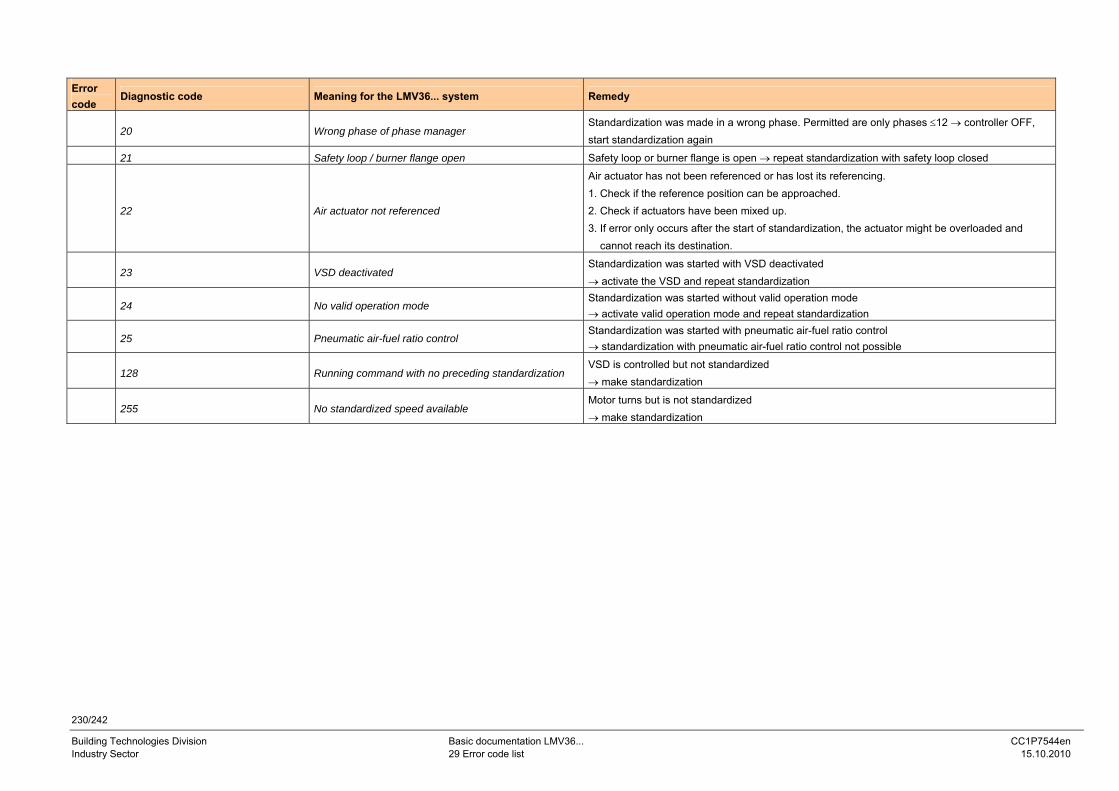
230/242
Building Technologies Division Basic documentation LMV36... CC1P7544en Industry Sector 29 Error code list 15.10.2010
Error code
Diagnostic code Meaning for the LMV36... system Remedy
20 Wrong phase of phase manager Standardization was made in a wrong phase. Permitted are only phases ≤12 → controller OFF, start standardization again
21 Safety loop / burner flange open Safety loop or burner flange is open → repeat standardization with safety loop closed
22 Air actuator not referenced
Air actuator has not been referenced or has lost its referencing. 1. Check if the reference position can be approached. 2. Check if actuators have been mixed up. 3. If error only occurs after the start of standardization, the actuator might be overloaded and cannot reach its destination.
23 VSD deactivated Standardization was started with VSD deactivated → activate the VSD and repeat standardization
24 No valid operation mode Standardization was started without valid operation mode → activate valid operation mode and repeat standardization
25 Pneumatic air-fuel ratio control Standardization was started with pneumatic air-fuel ratio control → standardization with pneumatic air-fuel ratio control not possible
128 Running command with no preceding standardization VSD is controlled but not standardized → make standardization
255 No standardized speed available Motor turns but is not standardized → make standardization
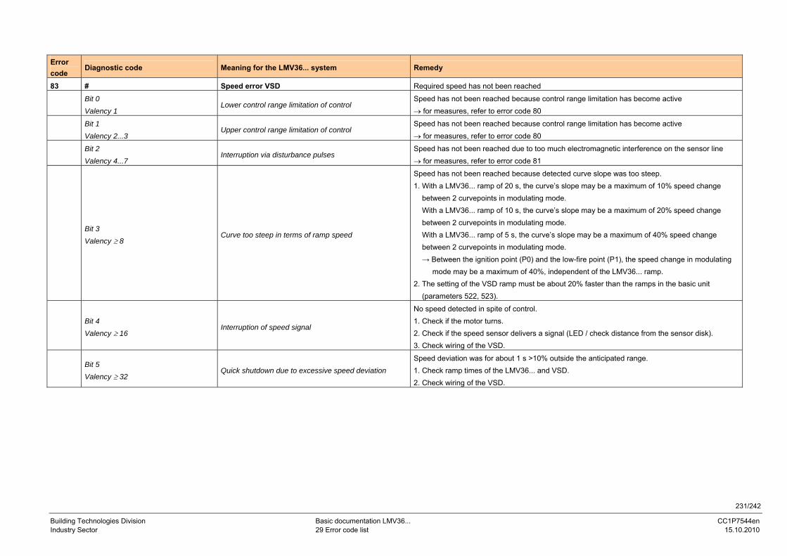
231/242
Building Technologies Division Basic documentation LMV36... CC1P7544en Industry Sector 29 Error code list 15.10.2010
Error code
Diagnostic code Meaning for the LMV36... system Remedy
83 # Speed error VSD Required speed has not been reached
Bit 0 Valency 1
Lower control range limitation of control Speed has not been reached because control range limitation has become active → for measures, refer to error code 80
Bit 1 Valency 2...3
Upper control range limitation of control Speed has not been reached because control range limitation has become active → for measures, refer to error code 80
Bit 2 Valency 4...7
Interruption via disturbance pulses Speed has not been reached due to too much electromagnetic interference on the sensor line → for measures, refer to error code 81
Bit 3 Valency ≥ 8
Curve too steep in terms of ramp speed
Speed has not been reached because detected curve slope was too steep. 1. With a LMV36... ramp of 20 s, the curve’s slope may be a maximum of 10% speed change between 2 curvepoints in modulating mode. With a LMV36... ramp of 10 s, the curve’s slope may be a maximum of 20% speed change between 2 curvepoints in modulating mode. With a LMV36... ramp of 5 s, the curve’s slope may be a maximum of 40% speed change between 2 curvepoints in modulating mode. → Between the ignition point (P0) and the low-fire point (P1), the speed change in modulating mode may be a maximum of 40%, independent of the LMV36... ramp. 2. The setting of the VSD ramp must be about 20% faster than the ramps in the basic unit (parameters 522, 523).
Bit 4 Valency ≥ 16
Interruption of speed signal
No speed detected in spite of control. 1. Check if the motor turns. 2. Check if the speed sensor delivers a signal (LED / check distance from the sensor disk). 3. Check wiring of the VSD.
Bit 5 Valency ≥ 32
Quick shutdown due to excessive speed deviation Speed deviation was for about 1 s >10% outside the anticipated range. 1. Check ramp times of the LMV36... and VSD. 2. Check wiring of the VSD.
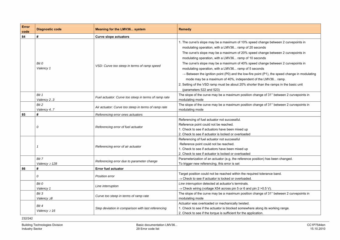
232/242
Building Technologies Division Basic documentation LMV36... CC1P7544en Industry Sector 29 Error code list 15.10.2010
Error code
Diagnostic code Meaning for the LMV36... system Remedy
84 # Curve slope actuators
Bit 0 Valency 1
VSD: Curve too steep in terms of ramp speed
1. The curve's slope may be a maximum of 10% speed change between 2 curvepoints in modulating operation, with a LMV36... ramp of 20 seconds The curve's slope may be a maximum of 20% speed change between 2 curvepoints in modulating operation, with a LMV36... ramp of 10 seconds The curve's slope may be a maximum of 40% speed change between 2 curvepoints in modulating operation, with a LMV36... ramp of 5 seconds → Between the ignition point (P0) and the low-fire point (P1), the speed change in modulating mode may be a maximum of 40%, independent of the LMV36... ramp. 2. Setting of the VSD ramp must be about 20% shorter than the ramps in the basic unit (parameters 522 and 523)
Bit 1 Valency 2..3
Fuel actuator: Curve too steep in terms of ramp rate The slope of the curve may be a maximum position change of 31° between 2 curvepoints in modulating mode
Bit 2 Valency 4..7
Air actuator: Curve too steep in terms of ramp rate The slope of the curve may be a maximum position change of 31° between 2 curvepoints in modulating mode
85 # Referencing error ones actuators
0 Referencing error of fuel actuator
Referencing of fuel actuator not successful. Reference point could not be reached. 1. Check to see if actuators have been mixed up 2. Check to see if actuator is locked or overloaded
1 Referencing error of air actuator
Referencing of fuel actuator not successful Reference point could not be reached. 1. Check to see if actuators have been mixed up 2. Check to see if actuator is locked or overloaded
Bit 7 Valency ≥ 128
Referencing error due to parameter change Parameterization of an actuator (e.g. the reference position) has been changed. To trigger new referencing, this error is set
86 # Error fuel actuator
0 Position error Target position could not be reached within the required tolerance band. → Check to see if actuator is locked or overloaded.
Bit 0 Valency 1
Line interruption Line interruption detected at actuator’s terminals. → Check wiring (voltage X54 across pin 5 or 6 and pin 2 >0.5 V).
Bit 3 Valency ≥8
Curve too steep in terms of ramp rate The slope of the curve may be a maximum position change of 31° between 2 curvepoints in modulating mode
Bit 4 Valency ≥ 16
Step deviation in comparison with last referencing Actuator was overloaded or mechanically twisted. 1. Check to see if the actuator is blocked somewhere along its working range. 2. Check to see if the torque is sufficient for the application.
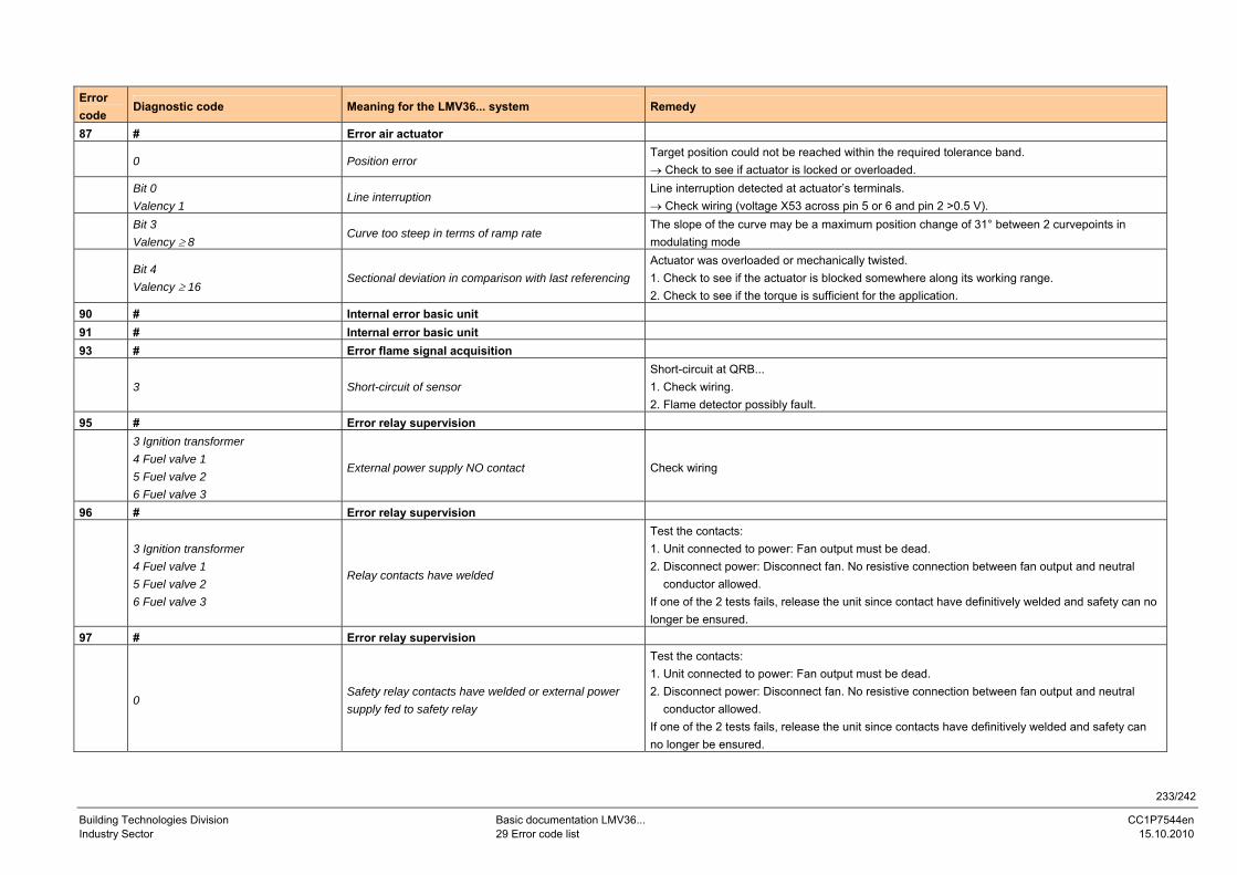
233/242
Building Technologies Division Basic documentation LMV36... CC1P7544en Industry Sector 29 Error code list 15.10.2010
Error code
Diagnostic code Meaning for the LMV36... system Remedy
87 # Error air actuator
0 Position error Target position could not be reached within the required tolerance band. → Check to see if actuator is locked or overloaded.
Bit 0 Valency 1
Line interruption Line interruption detected at actuator’s terminals. → Check wiring (voltage X53 across pin 5 or 6 and pin 2 >0.5 V).
Bit 3 Valency ≥ 8
Curve too steep in terms of ramp rate The slope of the curve may be a maximum position change of 31° between 2 curvepoints in modulating mode
Bit 4 Valency ≥ 16
Sectional deviation in comparison with last referencing Actuator was overloaded or mechanically twisted. 1. Check to see if the actuator is blocked somewhere along its working range. 2. Check to see if the torque is sufficient for the application.
90 # Internal error basic unit 91 # Internal error basic unit 93 # Error flame signal acquisition
3 Short-circuit of sensor Short-circuit at QRB... 1. Check wiring. 2. Flame detector possibly fault.
95 # Error relay supervision
3 Ignition transformer 4 Fuel valve 1 5 Fuel valve 2 6 Fuel valve 3
External power supply NO contact Check wiring
96 # Error relay supervision
3 Ignition transformer 4 Fuel valve 1 5 Fuel valve 2 6 Fuel valve 3
Relay contacts have welded
Test the contacts: 1. Unit connected to power: Fan output must be dead. 2. Disconnect power: Disconnect fan. No resistive connection between fan output and neutral conductor allowed. If one of the 2 tests fails, release the unit since contact have definitively welded and safety can no longer be ensured.
97 # Error relay supervision
0 Safety relay contacts have welded or external power supply fed to safety relay
Test the contacts: 1. Unit connected to power: Fan output must be dead. 2. Disconnect power: Disconnect fan. No resistive connection between fan output and neutral conductor allowed. If one of the 2 tests fails, release the unit since contacts have definitively welded and safety can no longer be ensured.
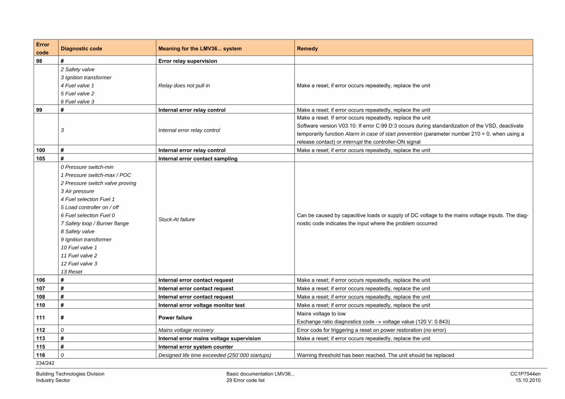
234/242
Building Technologies Division Basic documentation LMV36... CC1P7544en Industry Sector 29 Error code list 15.10.2010
Error code
Diagnostic code Meaning for the LMV36... system Remedy
98 # Error relay supervision
2 Safety valve 3 Ignition transformer 4 Fuel valve 1 5 Fuel valve 2 6 Fuel valve 3
Relay does not pull in Make a reset; if error occurs repeatedly, replace the unit
99 # Internal error relay control Make a reset; if error occurs repeatedly, replace the unit
3 Internal error relay control
Make a reset. If error occurs repeatedly, replace the unit Software version V03.10: If error C:99 D:3 occurs during standardization of the VSD, deactivate temporarily function Alarm in case of start prevention (parameter number 210 = 0, when using a release contact) or interrupt the controller-ON signal
100 # Internal error relay control Make a reset; if error occurs repeatedly, replace the unit 105 # Internal error contact sampling
0 Pressure switch-min 1 Pressure switch-max / POC 2 Pressure switch valve proving 3 Air pressure 4 Fuel selection Fuel 1 5 Load controller on / off 6 Fuel selection Fuel 0 7 Safety loop / Burner flange 8 Safety valve 9 Ignition transformer 10 Fuel valve 1 11 Fuel valve 2 12 Fuel valve 3 13 Reset
Stuck-At failure Can be caused by capacitive loads or supply of DC voltage to the mains voltage inputs. The diag-nostic code indicates the input where the problem occurred
106 # Internal error contact request Make a reset; if error occurs repeatedly, replace the unit 107 # Internal error contact request Make a reset; if error occurs repeatedly, replace the unit 108 # Internal error contact request Make a reset; if error occurs repeatedly, replace the unit 110 # Internal error voltage monitor test Make a reset; if error occurs repeatedly, replace the unit
111 # Power failure Mains voltage to low Exchange ratio diagnostics code → voltage value (120 V: 0.843)
112 0 Mains voltage recovery Error code for triggering a reset on power restoration (no error) 113 # Internal error mains voltage supervision Make a reset; if error occurs repeatedly, replace the unit 115 # Internal error system counter 116 0 Designed life time exceeded (250´000 startups) Warning threshold has been reached. The unit should be replaced
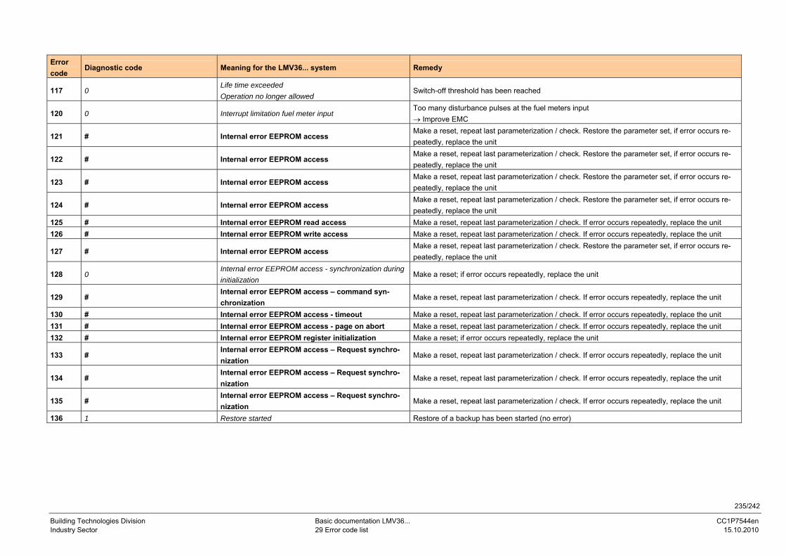
235/242
Building Technologies Division Basic documentation LMV36... CC1P7544en Industry Sector 29 Error code list 15.10.2010
Error code
Diagnostic code Meaning for the LMV36... system Remedy
117 0 Life time exceeded Operation no longer allowed
Switch-off threshold has been reached
120 0 Interrupt limitation fuel meter input Too many disturbance pulses at the fuel meters input → Improve EMC
121 # Internal error EEPROM access Make a reset, repeat last parameterization / check. Restore the parameter set, if error occurs re-peatedly, replace the unit
122 # Internal error EEPROM access Make a reset, repeat last parameterization / check. Restore the parameter set, if error occurs re-peatedly, replace the unit
123 # Internal error EEPROM access Make a reset, repeat last parameterization / check. Restore the parameter set, if error occurs re-peatedly, replace the unit
124 # Internal error EEPROM access Make a reset, repeat last parameterization / check. Restore the parameter set, if error occurs re-peatedly, replace the unit
125 # Internal error EEPROM read access Make a reset, repeat last parameterization / check. If error occurs repeatedly, replace the unit 126 # Internal error EEPROM write access Make a reset, repeat last parameterization / check. If error occurs repeatedly, replace the unit
127 # Internal error EEPROM access Make a reset, repeat last parameterization / check. Restore the parameter set, if error occurs re-peatedly, replace the unit
128 0 Internal error EEPROM access - synchronization during initialization
Make a reset; if error occurs repeatedly, replace the unit
129 # Internal error EEPROM access – command syn-chronization
Make a reset, repeat last parameterization / check. If error occurs repeatedly, replace the unit
130 # Internal error EEPROM access - timeout Make a reset, repeat last parameterization / check. If error occurs repeatedly, replace the unit 131 # Internal error EEPROM access - page on abort Make a reset, repeat last parameterization / check. If error occurs repeatedly, replace the unit 132 # Internal error EEPROM register initialization Make a reset; if error occurs repeatedly, replace the unit
133 # Internal error EEPROM access – Request synchro-nization
Make a reset, repeat last parameterization / check. If error occurs repeatedly, replace the unit
134 # Internal error EEPROM access – Request synchro-nization
Make a reset, repeat last parameterization / check. If error occurs repeatedly, replace the unit
135 # Internal error EEPROM access – Request synchro-nization
Make a reset, repeat last parameterization / check. If error occurs repeatedly, replace the unit
136 1 Restore started Restore of a backup has been started (no error)
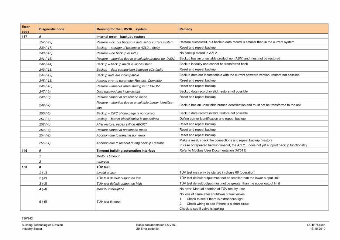
236/242
Building Technologies Division Basic documentation LMV36... CC1P7544en Industry Sector 29 Error code list 15.10.2010
Error code
Diagnostic code Meaning for the LMV36... system Remedy
137 # Internal error – backup / restore
157 (-99) Restore – ok, but backup < data set of current system Restore successful, but backup data record is smaller than in the current system
239 (-17) Backup – storage of backup in AZL2... faulty Reset and repeat backup
240 (-16) Restore – no backup in AZL2... No backup stored in AZL2...
241 (-15) Restore – abortion due to unsuitable product no. (ASN) Backup has an unsuitable product no. (ASN) and must not be restored
242 (-14) Backup – backup made is inconsistent Backup is faulty and cannot be transferred back
243 (-13) Backup – data comparison between µCs faulty Reset and repeat backup
244 (-12) Backup data are incompatible Backup data are incompatible with the current software version, restore not possible
245 (-11) Access error to parameter Restore_Complete Reset and repeat backup
246 (-10) Restore – timeout when storing in EEPROM Reset and repeat backup
247 (-9) Data received are inconsistent Backup data record invalid, restore not possible
248 (-8) Restore cannot at present be made Reset and repeat backup
249 (-7) Restore – abortion due to unsuitable burner identifica-tion
Backup has an unsuitable burner identification and must not be transferred to the unit
250 (-6) Backup – CRC of one page is not correct Backup data record invalid, restore not possible
251 (-5) Backup – burner identification is not defined Define burner identification and repeat backup
252 (-4) After restore, pages still on ABORT Reset and repeat backup
253 (-3) Restore cannot at present be made Reset and repeat backup
254 (-2) Abortion due to transmission error Reset and repeat backup
255 (-1) Abortion due to timeout during backup / restore Make a reset, check the connections and repeat backup / restore In case of repeated backup timeout, the AZL2... does not yet support backup functionality
146 # Timeout building automation interface Refer to Modbus User Documentation (A7541)
1 Modbus timeout
2 reserved
150 # TÜV test
1 (-1) Invalid phase TÜV test may only be started in phase 60 (operation)
2 (-2) TÜV test default output too low TÜV test default output must not be smaller than the lower output limit
3 (-3) TÜV test default output too high TÜV test default output must not be greater than the upper output limit
4 (-4) Manual interruption No error: Manual abortion of TÜV test by user
5 (-5) TÜV test timeout
No loss of flame after shutdown of fuel valves 1. Check to see if there is extraneous light 2. Check wiring to see if there is a short-circuit Check to see if valve is leaking
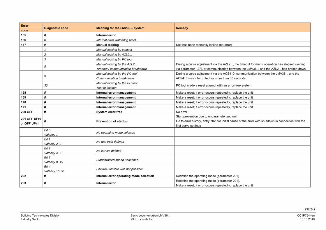
237/242
Building Technologies Division Basic documentation LMV36... CC1P7544en Industry Sector 29 Error code list 15.10.2010
Error code
Diagnostic code Meaning for the LMV36... system Remedy
165 # Internal error 166 0 Internal error watchdog reset 167 # Manual locking Unit has been manually locked (no error) 1 Manual locking by contact 2 Manual locking by AZL2... 3 Manual locking by PC tool
8 Manual locking by the AZL2... Timeout / communication breakdown
During a curve adjustment via the AZL2..., the timeout for menu operation has elapsed (setting via parameter 127), or communication between the LMV36... and the AZL2... has broken down
9 Manual locking by the PC tool Communication breakdown
During a curve adjustment via the ACS410, communication between the LMV36... and the ACS410 was interrupted for more than 30 seconds
33 Manual locking by the PC tool Test of lockout
PC tool made a reset attempt with an error-free system
168 # Internal error management Make a reset; if error occurs repeatedly, replace the unit 169 # Internal error management Make a reset; if error occurs repeatedly, replace the unit 170 # Internal error management Make a reset; if error occurs repeatedly, replace the unit 171 # Internal error management Make a reset; if error occurs repeatedly, replace the unit 200 OFF # System error-free No error
201 OFF UPr0 or OFF UPr1
# Prevention of startup Start prevention due to unparameterized unit Go to error history, entry 702, for initial cause of the error with shutdown in connection with the first curve settings
Bit 0 Valency 1
No operating mode selected
Bit 1 Valency 2..3
No fuel train defined
Bit 2 Valency 4..7
No curves defined
Bit 3 Valency 8..15
Standardized speed undefined
Bit 4 Valency 16..31
Backup / restore was not possible
202 # Internal error operating mode selection Redefine the operating mode (parameter 201)
203 # Internal error Redefine the operating mode (parameter 201). Make a reset; if error occurs repeatedly, replace the unit
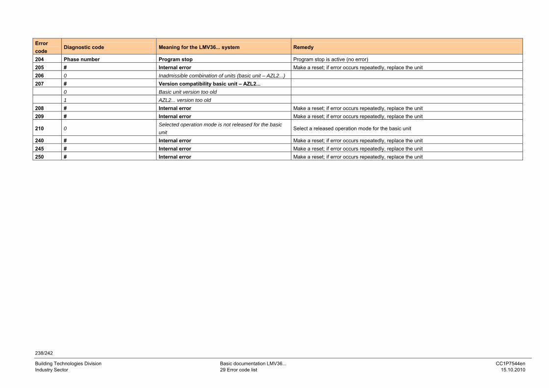
238/242
Building Technologies Division Basic documentation LMV36... CC1P7544en Industry Sector 29 Error code list 15.10.2010
Error code
Diagnostic code Meaning for the LMV36... system Remedy
204 Phase number Program stop Program stop is active (no error) 205 # Internal error Make a reset; if error occurs repeatedly, replace the unit 206 0 Inadmissible combination of units (basic unit – AZL2...) 207 # Version compatibility basic unit – AZL2... 0 Basic unit version too old 1 AZL2... version too old 208 # Internal error Make a reset; if error occurs repeatedly, replace the unit 209 # Internal error Make a reset; if error occurs repeatedly, replace the unit
210 0 Selected operation mode is not released for the basic unit
Select a released operation mode for the basic unit
240 # Internal error Make a reset; if error occurs repeatedly, replace the unit 245 # Internal error Make a reset; if error occurs repeatedly, replace the unit 250 # Internal error Make a reset; if error occurs repeatedly, replace the unit
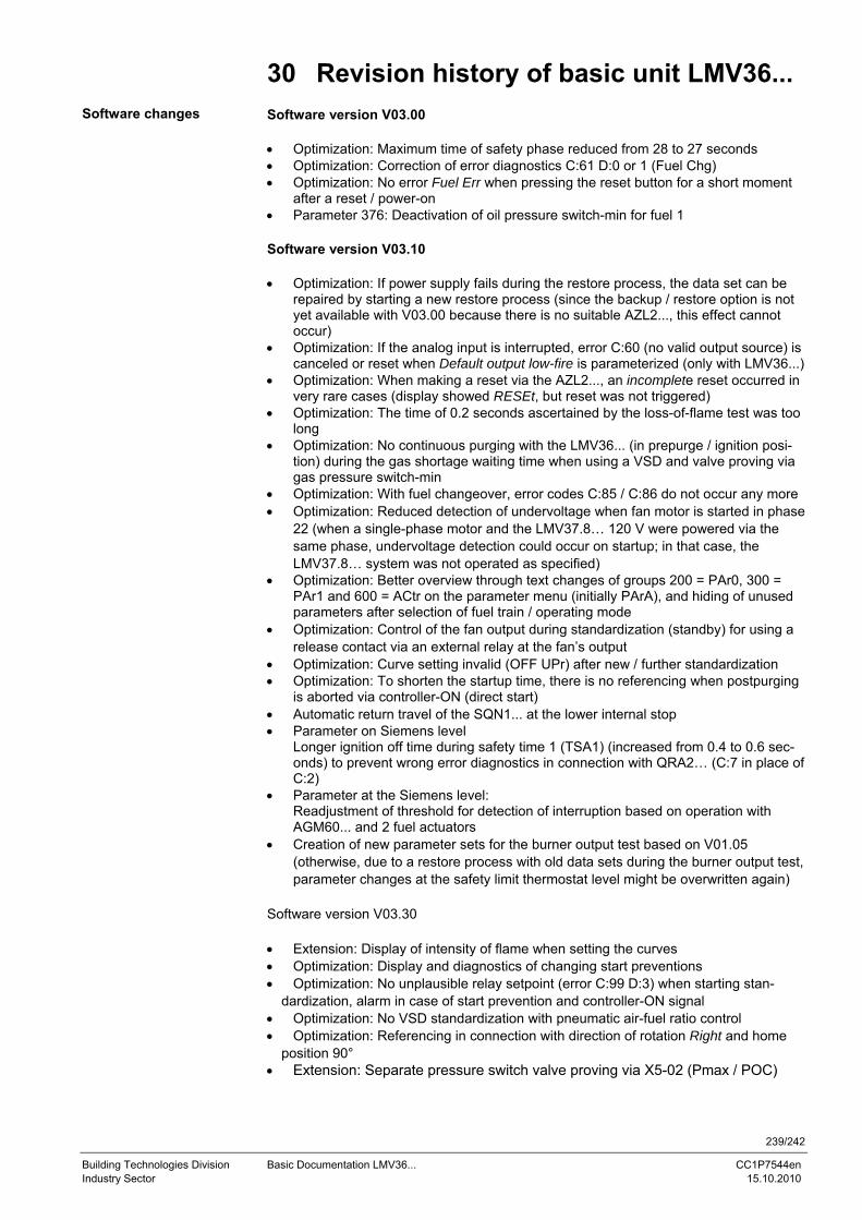
239/242
Building Technologies Division Basic Documentation LMV36... CC1P7544en Industry Sector 15.10.2010
30 Revision history of basic unit LMV36... Software version V03.00 • Optimization: Maximum time of safety phase reduced from 28 to 27 seconds • Optimization: Correction of error diagnostics C:61 D:0 or 1 (Fuel Chg) • Optimization: No error Fuel Err when pressing the reset button for a short moment
after a reset / power-on • Parameter 376: Deactivation of oil pressure switch-min for fuel 1 Software version V03.10 • Optimization: If power supply fails during the restore process, the data set can be
repaired by starting a new restore process (since the backup / restore option is not yet available with V03.00 because there is no suitable AZL2..., this effect cannot occur)
• Optimization: If the analog input is interrupted, error C:60 (no valid output source) is canceled or reset when Default output low-fire is parameterized (only with LMV36...)
• Optimization: When making a reset via the AZL2..., an incomplete reset occurred in very rare cases (display showed RESEt, but reset was not triggered)
• Optimization: The time of 0.2 seconds ascertained by the loss-of-flame test was too long
• Optimization: No continuous purging with the LMV36... (in prepurge / ignition posi-tion) during the gas shortage waiting time when using a VSD and valve proving via gas pressure switch-min
• Optimization: With fuel changeover, error codes C:85 / C:86 do not occur any more • Optimization: Reduced detection of undervoltage when fan motor is started in phase
22 (when a single-phase motor and the LMV37.8… 120 V were powered via the same phase, undervoltage detection could occur on startup; in that case, the LMV37.8… system was not operated as specified)
• Optimization: Better overview through text changes of groups 200 = PAr0, 300 = PAr1 and 600 = ACtr on the parameter menu (initially PArA), and hiding of unused parameters after selection of fuel train / operating mode
• Optimization: Control of the fan output during standardization (standby) for using a release contact via an external relay at the fan’s output
• Optimization: Curve setting invalid (OFF UPr) after new / further standardization • Optimization: To shorten the startup time, there is no referencing when postpurging
is aborted via controller-ON (direct start) • Automatic return travel of the SQN1... at the lower internal stop • Parameter on Siemens level
Longer ignition off time during safety time 1 (TSA1) (increased from 0.4 to 0.6 sec-onds) to prevent wrong error diagnostics in connection with QRA2… (C:7 in place of C:2)
• Parameter at the Siemens level: Readjustment of threshold for detection of interruption based on operation with AGM60... and 2 fuel actuators
• Creation of new parameter sets for the burner output test based on V01.05 (otherwise, due to a restore process with old data sets during the burner output test, parameter changes at the safety limit thermostat level might be overwritten again)
Software version V03.30 • Extension: Display of intensity of flame when setting the curves • Optimization: Display and diagnostics of changing start preventions • Optimization: No unplausible relay setpoint (error C:99 D:3) when starting stan-
dardization, alarm in case of start prevention and controller-ON signal • Optimization: No VSD standardization with pneumatic air-fuel ratio control • Optimization: Referencing in connection with direction of rotation Right and home
position 90° • Extension: Separate pressure switch valve proving via X5-02 (Pmax / POC)
Software changes
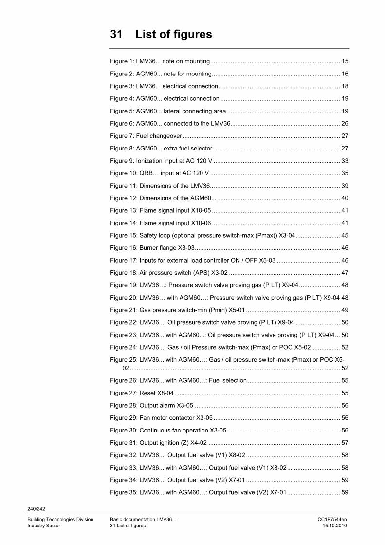
240/242
Building Technologies Division Basic documentation LMV36... CC1P7544en Industry Sector 31 List of figures 15.10.2010
31 List of figures Figure 1: LMV36... note on mounting............................................................................ 15 Figure 2: AGM60... note for mounting........................................................................... 16 Figure 3: LMV36... electrical connection....................................................................... 18 Figure 4: AGM60... electrical connection ...................................................................... 19 Figure 5: AGM60... lateral connecting area .................................................................. 19 Figure 6: AGM60... connected to the LMV36................................................................ 26 Figure 7: Fuel changeover ............................................................................................ 27 Figure 8: AGM60... extra fuel selector .......................................................................... 27 Figure 9: Ionization input at AC 120 V .......................................................................... 33 Figure 10: QRB… input at AC 120 V ............................................................................ 35 Figure 11: Dimensions of the LMV36............................................................................ 39 Figure 12: Dimensions of the AGM60... ........................................................................ 40 Figure 13: Flame signal input X10-05 ........................................................................... 41 Figure 14: Flame signal input X10-06 ........................................................................... 41 Figure 15: Safety loop (optional pressure switch-max (Pmax)) X3-04.......................... 45 Figure 16: Burner flange X3-03..................................................................................... 46 Figure 17: Inputs for external load controller ON / OFF X5-03 ..................................... 46 Figure 18: Air pressure switch (APS) X3-02 ................................................................. 47 Figure 19: LMV36…: Pressure switch valve proving gas (P LT) X9-04........................ 48 Figure 20: LMV36… with AGM60…: Pressure switch valve proving gas (P LT) X9-04 48 Figure 21: Gas pressure switch-min (Pmin) X5-01 ....................................................... 49 Figure 22: LMV36...: Oil pressure switch valve proving (P LT) X9-04 .......................... 50 Figure 23: LMV36... with AGM60...: Oil pressure switch valve proving (P LT) X9-04... 50 Figure 24: LMV36...: Gas / oil Pressure switch-max (Pmax) or POC X5-02................. 52 Figure 25: LMV36... with AGM60…: Gas / oil pressure switch-max (Pmax) or POC X5-
02........................................................................................................................... 52 Figure 26: LMV36... with AGM60…: Fuel selection ...................................................... 55 Figure 27: Reset X8-04................................................................................................. 55 Figure 28: Output alarm X3-05 ..................................................................................... 56 Figure 29: Fan motor contactor X3-05 .......................................................................... 56 Figure 30: Continuous fan operation X3-05 .................................................................. 56 Figure 31: Output ignition (Z) X4-02 ............................................................................. 57 Figure 32: LMV36...: Output fuel valve (V1) X8-02 ....................................................... 58 Figure 33: LMV36... with AGM60…: Output fuel valve (V1) X8-02............................... 58 Figure 34: LMV36...: Output fuel valve (V2) X7-01 ....................................................... 59 Figure 35: LMV36... with AGM60…: Output fuel valve (V2) X7-01............................... 59
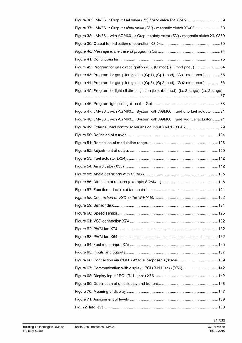
241/242
Building Technologies Division Basic Documentation LMV36... CC1P7544en Industry Sector 15.10.2010
Figure 36: LMV36...: Output fuel valve (V3) / pilot valve PV X7-02...............................59 Figure 37: LMV36...: Output safety valve (SV) / magnetic clutch X6-03 .......................60 Figure 38: LMV36... with AGM60…: Output safety valve (SV) / magnetic clutch X6-0360 Figure 39: Output for indication of operation X8-04.......................................................60 Figure 40: Message in the case of program stop ..........................................................74 Figure 41: Continuous fan .............................................................................................75 Figure 42: Program for gas direct ignition (G), (G mod), (G mod pneu) ........................84 Figure 43: Program for gas pilot ignition (Gp1), (Gp1 mod), (Gp1 mod pneu) ..............85 Figure 44: Program for gas pilot ignition (Gp2), (Gp2 mod), (Gp2 mod pneu) ..............86 Figure 45: Program for light oil direct ignition (Lo), (Lo mod), (Lo 2-stage), (Lo 3-stage)
...............................................................................................................................87 Figure 46: Program light pilot ignition (Lo Gp)...............................................................88 Figure 47: LMV36... with AGM60...: System with AGM60... and one fuel actuator .......91 Figure 48: LMV36... with AGM60...: System with AGM60... and two fuel actuator .......91 Figure 49: External load controller via analog input X64.1 / X64.2................................99 Figure 50: Definition of curves.....................................................................................104 Figure 51: Restriction of modulation range..................................................................106 Figure 52: Adjustment of output ..................................................................................109 Figure 53: Fuel actuator (X54).....................................................................................112 Figure 54: Air actuator (X53) .......................................................................................112 Figure 55: Angle definitions with SQM33….................................................................115 Figure 56: Direction of rotation (example SQM3…).....................................................116 Figure 57: Function principle of fan control .................................................................121 Figure 58: Connection of VSD to the W-FM 50 ...........................................................122 Figure 59: Sensor disk.................................................................................................124 Figure 60: Speed sensor .............................................................................................125 Figure 61: VSD connection X74 ..................................................................................132 Figure 62: PWM fan X74 .............................................................................................132 Figure 63: PWM fan X64 .............................................................................................132 Figure 64: Fuel meter input X75 ..................................................................................135 Figure 65: Inputs and outputs......................................................................................137 Figure 66: Connection via COM X92 to superposed systems.....................................139 Figure 67: Communication with display / BCI (RJ11 jack) (X56) .................................142 Figure 68: Display input / BCI (RJ11 jack) X56 ...........................................................142 Figure 69: Description of unit/display and buttons.......................................................146 Figure 70: Meaning of display .....................................................................................147 Figure 71: Assignment of levels ..................................................................................159 Fig. 72: Info level .........................................................................................................160
242/242
Building Technologies Division Basic documentation LMV36... CC1P7544en Industry Sector 31 List of figures 15.10.2010
Figure 73: Service level .............................................................................................. 165 Figure 74: Setting the curvepoints .............................................................................. 191 Figure 75: Changing several curvepoints ................................................................... 197
Siemens AG Industry Sector Building Technologies Division Berliner Ring 23 D-76437 Rastatt Tel. 0049-7222-598-279 Fax 0049-7222-598-269 www.sbt.siemens.com
© 2010 Siemens AG Industry Sector Building Technologies Division Subject to change!