Embed Size (px)
Citation preview
Page 1
INTERNATIONAL
RECOMMENDATION OIML R 49-3 Edition 2009 (E)
Water meters intended for the metering of cold potable water and hot water Part 3: Test Report Format
ORGANISATION INTERNATIONALE DE MÉTROLOGIE LÉGALE INTERNATIONAL ORGANIZATION OF LEGAL METROLOGY
Page 2
Contents
Explanatory notes to the Test Report Format …………………………………………………………… 4I. Type evaluation report …………………………………………………………………………………….. 51 INFORMATION CONCERNING THE TYPE ……………………………………………………………… 5 1.1 General …………………………………………………………………………………………………... 5 1.2 Model submitted ………………………………………………………………………………………... 5 1.3 Mechanical water meter (complete or combined) …………………………………………………… 7 1.4 Electronic water meter (complete or combined) …………………………………………………….. 8 1.5 Separable calculator (including indicating device) 9 1.6 Separable measurement transducer (including flow or volume sensor) ………………………….. 10 1.7 Supplementary electronic device/s used for testing (permanently attached to meter) ………….. 11 1.8 Supplementary electronic device/s used for data transmission (permanently attached to meter) 11 1.9 Supplementary electronic device/s used for testing (temporarily attached to meter) …………… 12 1.10 Supplementary electronic device/s used for data transmission (temporarily attached to meter) 12 1.11 Ancillary devices ………………………………………………………………………………………. 122 DOCUMENTS CONCERNING THE TYPE ………………………………………………………………. 133 GENERAL INFORMATION CONCERNING THE TEST EQUIPMENT ……………………………… 134 CHECK LIST FOR WATER METER EXAMINATIONS AND PERFORMANCE TESTS ……………. 14 4.1 Check list for water meter examinations ……………………………………………………………... 14 4.2 Checklist for water meter performance tests ………………………………………………………… 225 TYPE EVALUATION TESTS (FOR ALL WATER METERS) ………………………………………….. 30 5.1 Static pressure test (R 49-2 Section 6.2) …………………………………………………………….. 30 5.2 Determination of changeover flowrates for combination meters (R 49-2 Section 6.3.3) ………... 31 5.3 Determination of the intrinsic errors (of indication) and the effects of meter orientation (R 49-2 Section 6.3.4) ……………………………………………………………... 32 5.4 Water temperature test (R 49-2 Section 6.5) ………………………………………………………… 34 5.5 Water pressure test (R 49-2 Section 6.7) ……………………………………………………………. 35 5.6 Flow reversal test (R 49-2 Section 6.8) ………………………………………………………………. 36 5.7 Pressure-loss test (R 49-2, Section 6.9) ……………………………………………………………... 38 5.8 Flow disturbance tests (R 49-2, Section 6.10 and Annex C) ………………………………………. 39 5.9 Endurance tests (R 49-2, Section 6.11) ……………………………………………………………… 42 5.10 Static magnetic field test (R42-2 Section 6.12 & 7.12) ……………………………………………. 486 TYPE EVALUATION TESTS (FOR ELECTRONIC WATER METERS ANDMECHANICAL WATER METERS WITH ELECTRONIC COMPONENTS) …………………………….. 49 6.1 Dry heat (non-condensing) (R 49-2 Section 7.2) ……………………………………………………. 49 6.2 Cold (R 49-2 Section 7.3) ……………………………………………………………………………… 50 6.3 Damp heat, cyclic (condensing) (R 49-2 Section 7.4) ……………………………………………… 51 6.4 Power voltage variation (R 49-2 Section 7.5) ……………………………………………………….. 52 6.5 Vibration (random) (R 49-2 Section 7.6) ……………………………………………………………... 53 6.6 Mechanical shock (R 49-2 Section 7.7) ……………………………………………………………… 54 6.7 Short-time power reductions (R 49-2 Section 7.8) ………………………………………………….. 55 6.8 Bursts (R 49-2 Section 7.9) ……………………………………………………………………………. 56 6.9 Electrostatic discharge (R 49-2 Section 7.10) ……………………………………………………….. 57 6.10 Electromagnetic susceptibility (R 49-2 Section 7.11) ……………………………………………… 58II. Initial verification report …………………………………………………………………………………. 591 INFORMATION CONCERNING THE EUT VERIFIED ………………………………………………… 592 INITIAL VERIFICATION TEST REPORT (R 49-2, 9) ………………………………………………….. 60ANNEX A ……………………………………………………………………………………………………….. 63ANNEX B ……………………………………………………………………………………………………….. 64
Explanatory notes to the Test Report Format .............................................................................................4 I. Type evaluation report ...........................................................................................................................5
Formatted ... [1]
Formatted Table ... [2]
Formatted ... [3]
Formatted ... [4]
Formatted ... [5]
Formatted ... [6]
Formatted ... [7]
Formatted ... [8]
Formatted ... [9]
Formatted ... [10]
Formatted ... [11]
Formatted ... [12]
Formatted ... [13]
Formatted ... [14]
Formatted ... [15]
Formatted ... [16]
Formatted ... [17]
Formatted ... [18]
Formatted ... [19]
Formatted ... [20]
Formatted ... [21]
Formatted ... [22]
Formatted ... [23]
Formatted ... [24]
Formatted ... [25]
Formatted ... [26]
Formatted ... [27]
Formatted ... [28]
Formatted ... [29]
Formatted ... [30]
Formatted ... [31]
Formatted ... [32]
Formatted ... [33]
Formatted ... [34]
Formatted ... [35]
Formatted ... [36]
Formatted ... [37]
Formatted ... [38]
Formatted ... [39]
Formatted ... [40]
Formatted ... [41]
Formatted ... [42]
Formatted ... [43]
Formatted ... [44]
Formatted ... [45]
Formatted ... [46]
Formatted ... [47]
Formatted ... [48]
Formatted ... [49]
Formatted ... [50]
Formatted ... [51]
Formatted ... [52]
Formatted ... [53]
Formatted ... [54]
Formatted ... [55]
Formatted ... [56]
Formatted ... [57]
Formatted ... [58]
Formatted ... [59]
Formatted ... [60]
Formatted ... [61]
Page 3
1 INFORMATION CONCERNING THE TYPE................................................................................5 1.1 General...............................................................5 1.2 Model submitted ......................................................5 1.3 Mechanical water meter (complete or combined).........................7 1.4 Electronic water meter (complete or combined) .......................8 1.5 Separable calculator (including indicating device) ..................9 1.6 Separable measurement transducer (including flow or volume sensor) ...10 1.7 Supplementary electronic device/s used for testing (permanently attached to meter) ..........11 1.8 Supplementary electronic device/s used for data transmission (permanently attached to meter) 1.9 Supplementary electronic device/s used for testing (temporarily attached to meter)..........12 1.10 Supplementary electronic device/s used for data transmission (temporarily attached to meter)..........12 1.11 Ancillary devices ...........................................................12 2 DOCUMENTS CONCERNING THE TYPE .................................................................................13 3 GENERAL INFORMATION CONCERNING THE TEST EQUIPMENT................................13 4 CHECK LIST FOR WATER METER EXAMINATIONS AND PERFORMANCE TESTS...14 4.1 Check list for water meter examinations...............................................................................14 4.2 Checklist for water meter performance tests.........................................................................24 5 TYPE EVALUATION TESTS (FOR ALL WATER METERS)..................................................31 5.1 Static pressure test (R 49-2 Section 6.2) ...............................................................................31 5.2 Determination of changeover flowrates for combination meters (R 49-2 Section 6.3.3) .....32 5.3 Determination of the intrinsic errors (of indication) and the effects of meter orientation (R 49-2 Section 6.3.4)...............................................................................33 5.4 Water temperature test (R 49-2 Section 6.4).........................................................................35 5.5 Water pressure test (R 49-2 Section 6.5) ..............................................................................36 5.6 Flow reversal test (R 49-2 Section 6.6) ................................................................................37 5.7 Pressure-loss test (R 49-2, Section 6.7) ................................................................................39 5.8 Flow disturbance tests (R 49-2, Section 6.8 and Annex C) ..................................................40 5.9 Endurance tests (R 49-2, Section 6.9)...................................................................................43 5.10 Static magnetic field test (R42-2 Section 6.10 & 7.12) ........................................................49 6 TYPE EVALUATION TESTS (FOR ELECTRONIC WATER METERS AND MECHANICAL WATER METERS WITH ELECTRONIC COMPONENTS)........................50 6.1 Dry heat (non-condensing) (R 49-2 Section 7.2)..................................................................50 6.2 Cold (R 49-2 Section 7.3) .....................................................................................................51 6.3 Damp heat, cyclic (condensing) (R 49-2 Section 7.4) ..........................................................52 6.4 Power voltage variation (R 49-2 Section 7.5).......................................................................53 6.5 Vibration (random) (R 49-2 Section 7.6)..............................................................................54 6.6 Mechanical shock (R 49-2 Section 7.7) ................................................................................55 6.7 Short-time power reductions (R 49-2 Section 7.8) ...............................................................56 6.8 Bursts (R 49-2 Section 7.9)...................................................................................................57 6.9 Electrostatic discharge (R 49-2 Section 7.10).......................................................................58 6.10 Electromagnetic susceptibility (R 49-2 Section 7.11)...........................................................59 II. Initial verification report .....................................................................................................................60 1 INFORMATION CONCERNING THE EUT VERIFIED............................................................60 2 INITIAL VERIFICATION TEST REPORT (R 49-2, 9)...............................................................61 ANNEX A..................................................................................................................................................64 ANNEX B ..................................................................................................................................................65
Page 4
Foreword The International Organization of Legal Metrology (OIML) is a worldwide, intergovernmental organization whose primary aim is to harmonize the regulations and metrological controls applied by the national metrological services, or related organizations, of its Member States. The main categories of OIML publications are:
• International Recommendations (OIML R), which are model regulations that establish the metrological characteristics required of certain measuring instruments and which specify methods and equipment for checking their conformity. OIML Member States shall implement these Recommendations to the greatest possible extent;
• International Documents (OIML D), which are informative in nature and which are intended to harmonize and improve work in the field of legal metrology;
• International Guides (OIML G), which are also informative in nature and which are intended to give guidelines for the application of certain requirements to legal metrology; and
• International Basic Publications (OIML B), which define the operating rules of the various OIML structures and systems.
OIML Draft Recommendations, Documents and Guides are developed by Technical Committees or Subcommittees which comprise representatives from the Member States. Certain international and regional institutions also participate on a consultation basis. Cooperative agreements have been established between the OIML and certain institutions, such as ISO and the IEC, with the objective of avoiding contradictory requirements. Consequently, manufacturers and users of measuring instruments, test laboratories, etc. may simultaneously apply OIML publications and those of other institutions. International Recommendations, Documents, Guides and Basic Publications are published in English (E) and translated into French (F) and are subject to periodic revision. Additionally, the OIML publishes or participates in the publication of Vocabularies (OIML V) and periodically commissions legal metrology experts to write Expert Reports (OIML E). Expert Reports are intended to provide information and advice, and are written solely from the viewpoint of their author, without the involvement of a Technical Committee or Subcommittee, nor that of the CIML. Thus, they do not necessarily represent the views of the OIML. This publication - reference OIML R 49-3, Edition 2006 - was developed by the Subcommittee TC 8/SC 5 Water meters. This version supersedes OIML R 49-3 Water meters intended for the metering of cold potable water. Part 3: Test Report Format (Edition 2004) and OIML R 72 Hot water meters (Edition1985). It was approved for final publication by the International Committee of Legal Metrology in 2006. OIML Publications may be downloaded from the OIML web site in the form of PDF files. Additional information on OIML Publications may be obtained from the Organization’s headquarters: Bureau International de Métrologie Légale 11, rue Turgot - 75009 Paris - France Telephone: 33 (0)1 48 78 12 82 Fax: 33 (0)1 42 82 17 27 E-mail: [email protected] Internet: www.oiml.org
Page 5
Water meters intended for the metering of cold potable water and hot water
Part 3: Test Report Format
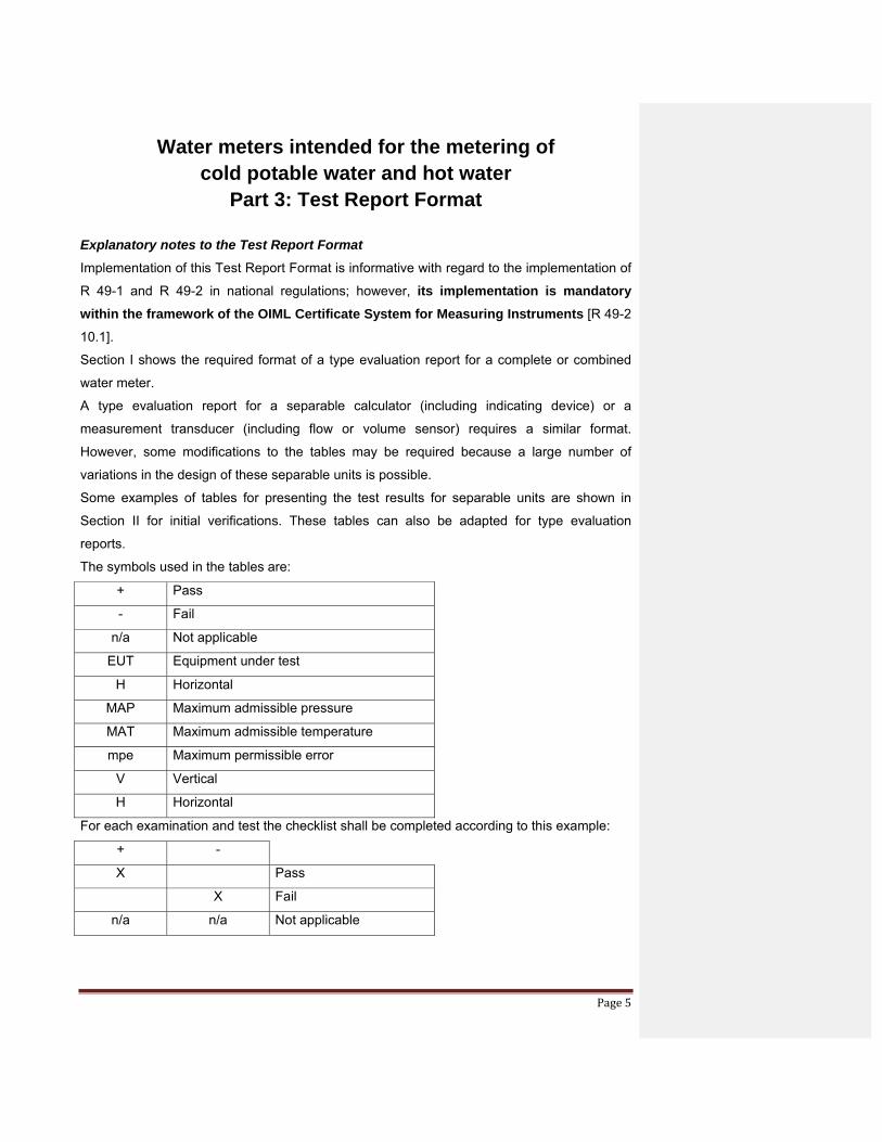
Explanatory notes to the Test Report Format
Implementation of this Test Report Format is informative with regard to the implementation of
R 49-1 and R 49-2 in national regulations; however, its implementation is mandatory within the framework of the OIML Certificate System for Measuring Instruments [R 49-2
10.1].
Section I shows the required format of a type evaluation report for a complete or combined
water meter.
A type evaluation report for a separable calculator (including indicating device) or a
measurement transducer (including flow or volume sensor) requires a similar format.
However, some modifications to the tables may be required because a large number of
variations in the design of these separable units is possible.
Some examples of tables for presenting the test results for separable units are shown in
Section II for initial verifications. These tables can also be adapted for type evaluation
reports.
The symbols used in the tables are:
+ Pass
- Fail
n/a Not applicable
EUT Equipment under test
H Horizontal
MAP Maximum admissible pressure
MAT Maximum admissible temperature
mpe Maximum permissible error
V Vertical
H Horizontal
For each examination and test the checklist shall be completed according to this example:
+ -
X Pass
X Fail
n/a n/a Not applicable
OIML R 49-3: 2009 (E) draft 1 Report number:…………… Report page …./….
Page 6
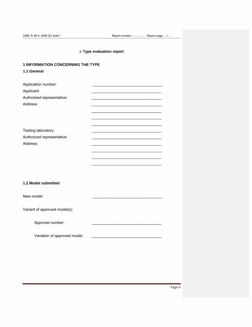
I. Type evaluation report 1 INFORMATION CONCERNING THE TYPE 1.1 General
Application number: _________________________________
Applicant: _________________________________
Authorized representative: _________________________________
Address: _________________________________
_________________________________
_________________________________
_________________________________
Testing laboratory: _________________________________
Authorized representative: _________________________________
Address: _________________________________
_________________________________
_________________________________
_________________________________
1.2 Model submitted
New model: _________________________________
Variant of approved model(s):
Approval number: _________________________________
Variation of approved model: _________________________________
OIML R 49-3: 2009 (E) draft 1 Report number:…………… Report page …./….
Page 7
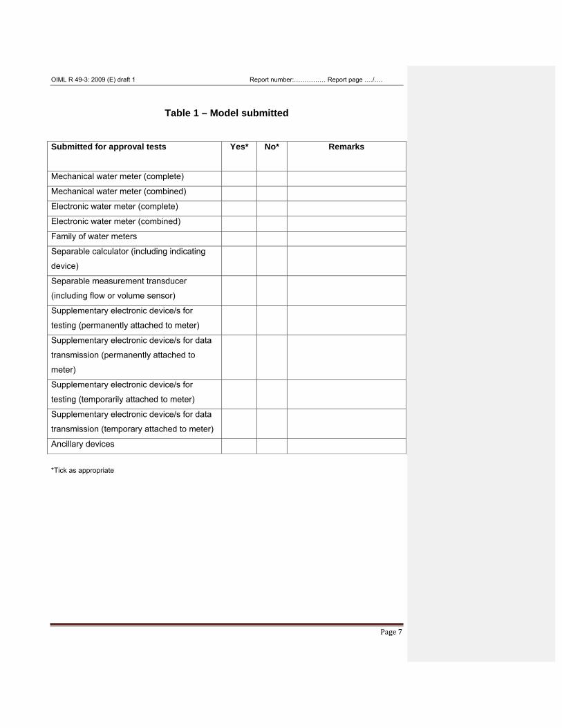
Table 1 – Model submitted
Submitted for approval tests Yes*
No* Remarks
Mechanical water meter (complete)
Mechanical water meter (combined)
Electronic water meter (complete)
Electronic water meter (combined)
Family of water meters
Separable calculator (including indicating
device)
Separable measurement transducer
(including flow or volume sensor)
Supplementary electronic device/s for
testing (permanently attached to meter)
Supplementary electronic device/s for data
transmission (permanently attached to
meter)
Supplementary electronic device/s for
testing (temporarily attached to meter)
Supplementary electronic device/s for data
transmission (temporary attached to meter)
Ancillary devices
*Tick as appropriate
OIML R 49-3: 2009 (E) draft 1 Report number:…………… Report page …./….
Page 8
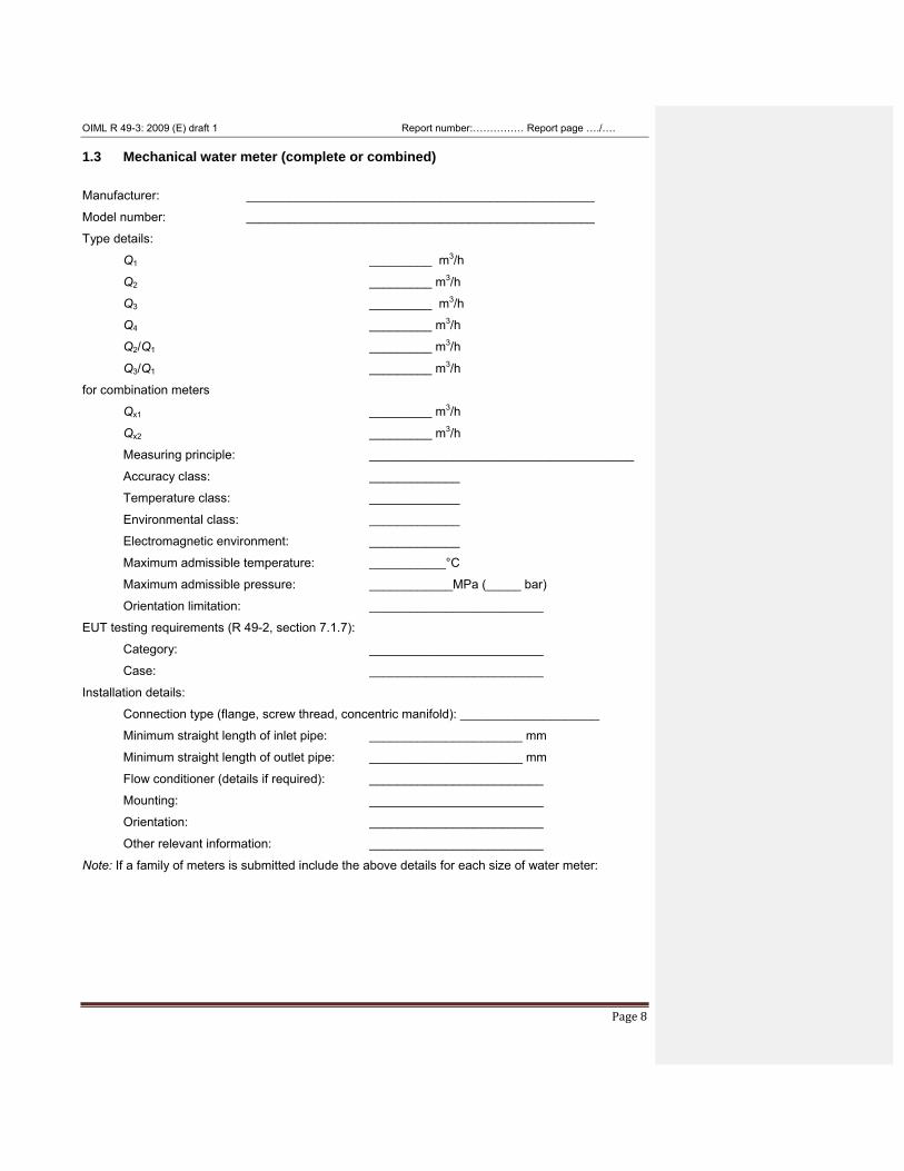
1.3 Mechanical water meter (complete or combined) Manufacturer: __________________________________________________
Model number: __________________________________________________
Type details:
Q1 _________ m3/h
Q2 _________ m3/h
Q3 _________ m3/h
Q4 _________ m3/h
Q2/Q1 _________ m3/h
Q3/Q1 _________ m3/h
for combination meters
Qx1 _________ m3/h
Qx2 _________ m3/h
Measuring principle: ______________________________________
Accuracy class: _____________
Temperature class: _____________
Environmental class: _____________
Electromagnetic environment: _____________
Maximum admissible temperature: ___________°C
Maximum admissible pressure: ____________MPa (_____ bar)
Orientation limitation: _________________________
EUT testing requirements (R 49-2, section 7.1.7):
Category: _________________________
Case: _________________________
Installation details:
Connection type (flange, screw thread, concentric manifold): ____________________
Minimum straight length of inlet pipe: ______________________ mm
Minimum straight length of outlet pipe: ______________________ mm
Flow conditioner (details if required): _________________________
Mounting: _________________________
Orientation: _________________________
Other relevant information: _________________________
Note: If a family of meters is submitted include the above details for each size of water meter:
OIML R 49-3: 2009 (E) draft 1 Report number:…………… Report page …./….
Page 9
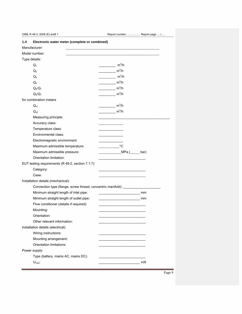
1.4 Electronic water meter (complete or combined) Manufacturer: __________________________________________________
Model number: __________________________________________________
Type details:
Q1 _________ m3/h
Q2 _________ m3/h
Q3 _________ m3/h
Q4 _________ m3/h
Q2/Q1 _________ m3/h
Q3/Q1 _________ m3/h
for combination meters
Qx1 _________ m3/h
Qx2 _________ m3/h
Measuring principle: ______________________________________
Accuracy class: _____________
Temperature class: _____________
Environmental class: _____________
Electromagnetic environment: _____________
Maximum admissible temperature: ___________°C
Maximum admissible pressure: ____________MPa (_____ bar)
Orientation limitation: _________________________
EUT testing requirements (R 49-2, section 7.1.7):
Category: _________________________
Case: _________________________
Installation details (mechanical):
Connection type (flange, screw thread, concentric manifold): ____________________
Minimum straight length of inlet pipe: ______________________ mm
Minimum straight length of outlet pipe: ______________________ mm
Flow conditioner (details if required): _________________________
Mounting: _________________________
Orientation: _________________________
Other relevant information: _________________________
Installation details (electrical):
Wiring instructions: _________________________
Mounting arrangement: _________________________
Orientation limitations: _________________________
Power supply:
Type (battery, mains AC, mains DC): _________________________
Umax: ______________________ volt
OIML R 49-3: 2009 (E) draft 1 Report number:…………… Report page …./….
Page 10
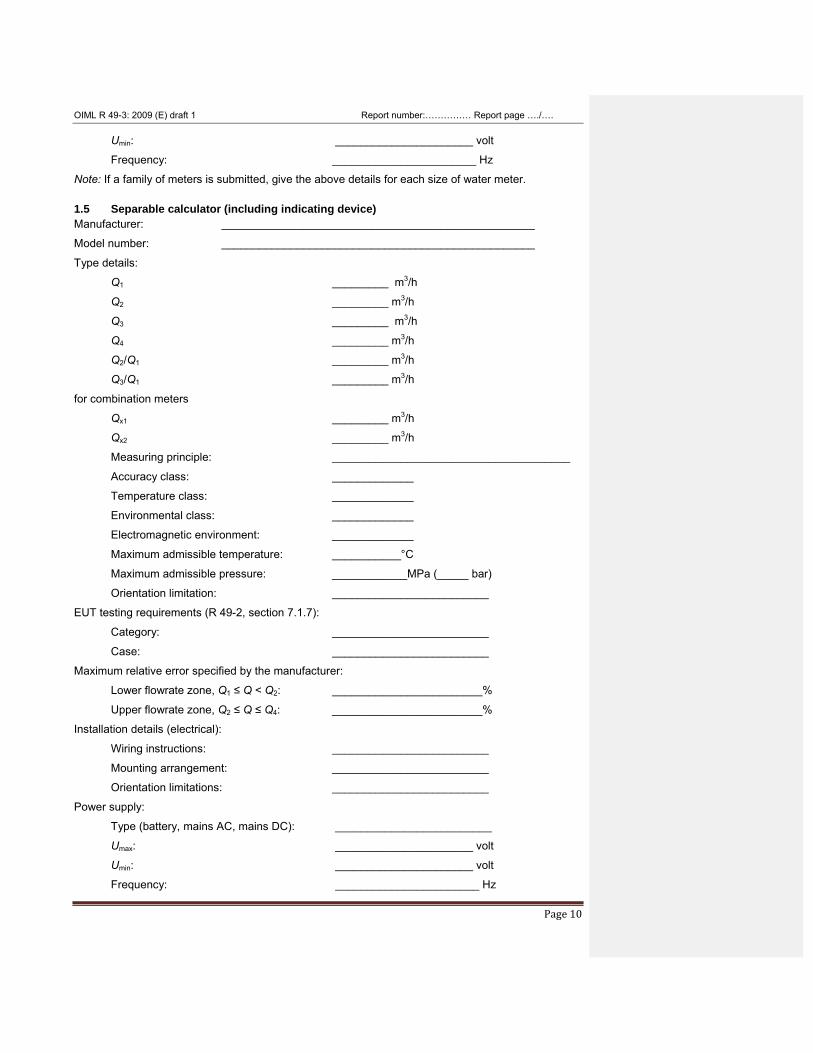
Umin: ______________________ volt
Frequency: _______________________ Hz
Note: If a family of meters is submitted, give the above details for each size of water meter. 1.5 Separable calculator (including indicating device) Manufacturer: __________________________________________________
Model number: __________________________________________________
Type details:
Q1 _________ m3/h
Q2 _________ m3/h
Q3 _________ m3/h
Q4 _________ m3/h
Q2/Q1 _________ m3/h
Q3/Q1 _________ m3/h
for combination meters
Qx1 _________ m3/h
Qx2 _________ m3/h
Measuring principle: ______________________________________
Accuracy class: _____________
Temperature class: _____________
Environmental class: _____________
Electromagnetic environment: _____________
Maximum admissible temperature: ___________°C
Maximum admissible pressure: ____________MPa (_____ bar)
Orientation limitation: _________________________
EUT testing requirements (R 49-2, section 7.1.7):
Category: _________________________
Case: _________________________
Maximum relative error specified by the manufacturer:
Lower flowrate zone, Q1 ≤ Q < Q2: ________________________%
Upper flowrate zone, Q2 ≤ Q ≤ Q4: ________________________%
Installation details (electrical):
Wiring instructions: _________________________
Mounting arrangement: _________________________
Orientation limitations: _________________________
Power supply:
Type (battery, mains AC, mains DC): _________________________
Umax: ______________________ volt
Umin: ______________________ volt
Frequency: _______________________ Hz
OIML R 49-3: 2009 (E) draft 1 Report number:…………… Report page …./….
Page 11
Approval number(s) of compatible measurement
Transducer(s) (including flow or volume sensor):____________________
1.6 Separable measurement transducer (including flow or volume sensor) Manufacturer: __________________________________________________
Model number: __________________________________________________
Type details:
Q1 _________ m3/h
Q2 _________ m3/h
Q3 _________ m3/h
Q4 _________ m3/h
Q2/Q1 _________ m3/h
Q3/Q1 _________ m3/h
for combination meters
Qx1 _________ m3/h
Qx2 _________ m3/h
Measuring principle: ______________________________________
Accuracy class: _____________
Temperature class: _____________
Environmental class: _____________
Electromagnetic environment: _____________
Maximum admissible temperature: ___________°C
Maximum admissible pressure: ____________MPa (_____ bar)
Orientation limitation: _________________________
EUT testing requirements (R 49-2, section 7.1.7):
Category: _________________________
Case: _________________________
Maximum relative error specified by the manufacturer:
Lower flowrate zone, Q1 ≤ Q < Q2: ________________________%
Upper flowrate zone, Q2 ≤ Q ≤ Q4: ________________________%
Installation details mechanical):
Connection type (flange, screw thread, concentric manifold): __________
Minimum straight length of inlet pipe: ______________________ mm
Minimum straight length of outlet pipe: ______________________ mm
Flow conditioner (details if required): _________________________
Mounting: _________________________
Orientation: _________________________
Other relevant information: _________________________
OIML R 49-3: 2009 (E) draft 1 Report number:…………… Report page …./….
Page 12
Installation details (electrical):
Wiring instructions: _________________________
Mounting arrangement: _________________________
Orientation limitations: _________________________
Power supply:
Type (battery, mains AC, mains DC): _________________________
Umax: ______________________ volt
Umin: ______________________ volt
Frequency: _______________________ Hz
Approval number(s) of compatible
calculator(s) (including indicating device): _________________________
1.7 Supplementary electronic device/s used for testing (permanently attached to meter) Manufacturer: __________________________________________________
Model number: __________________________________________________
Power supply:
Type (battery, mains AC, mains DC): _________________________
Umax: ______________________ volt
Umin: ______________________ volt
Frequency: _______________________ Hz
Installation details (electrical):
Wiring instructions: _________________________
Mounting arrangement: _________________________
Orientation limitations: _________________________
1.8 Supplementary electronic device/s used for data transmission
(permanently attached to meter) Manufacturer: __________________________________________________
Model number: __________________________________________________
Power supply:
Type (battery, mains AC, mains DC): _________________________
Umax: ______________________ volt
Umin: ______________________ volt
Frequency: _______________________ Hz
Installation details (electrical):
Wiring instructions: _________________________
Mounting arrangement: _________________________
Orientation limitations: _________________________
OIML R 49-3: 2009 (E) draft 1 Report number:…………… Report page …./….
Page 13
1.9 Supplementary electronic device/s used for testing (temporarily attached to meter) Manufacturer: __________________________________________________
Model number: __________________________________________________
Power supply:
Type (battery, mains AC, mains DC): _________________________
Umax: ______________________ volt
Umin: ______________________ volt
Frequency: _______________________ Hz
Installation details (electrical):
Wiring instructions: _________________________
Mounting arrangement: _________________________
Orientation limitations: _________________________
1.10 Supplementary electronic device/s used for data transmission
(temporarily attached to meter) Manufacturer: __________________________________________________
Model number: __________________________________________________
Power supply:
Type (battery, mains AC, mains DC): _________________________
Umax: ______________________ volt
Umin: ______________________ volt
Frequency: _______________________ Hz
EUT testing requirements (R 49-2, section 7.1.7):
Category: _________________________
Case: _________________________
Installation details (electrical):
Wiring instructions: _________________________
Mounting arrangement: _________________________
Orientation limitations: _________________________
1.11 Ancillary devices Manufacturer: __________________________________________________
Model number: __________________________________________________
Power supply:
Type (battery, mains AC, mains DC): _________________________
Umax: ______________________ volt
Umin: ______________________ volt
Frequency: _______________________ Hz
OIML R 49-3: 2009 (E) draft 1 Report number:…………… Report page …./….
Page 14
Approval number(s) of compatible calculator(s) (including indicating device):
_________________________
EUT testing requirements (R 49-2, section 7.1.7):
Category: _________________________
Case: _________________________
Installation details (electrical):
Wiring instructions: _________________________
Mounting arrangement: _________________________
Orientation limitations: _________________________
Approval number(s) of compatible water meters,
calculator(s) (including indicating device and
measurement transducer(s) (including flow or
volume sensor): _________________________
2 DOCUMENTS CONCERNING THE TYPE A model list of documents submitted with the type approval application is given in Annex A.
3 GENERAL INFORMATION CONCERNING THE TEST EQUIPMENT Details of all items of measuring equipment and test instruments used for the type examinations, and
initial verifications shall be listed in Annex B, including:
Manufacturer
Model number
Serial number
Date of last calibration
Date of next calibration due of e.g. instruments for measuring:
• linear dimensions
• pressure gauges
• pressure transmitters
• manometers
• temperature transducers
• reference meters
• volume tanks
• weighing machines
• signal generators (for pulse, current or voltage)
OIML R 49-3: 2009 (E) draft 1 Report number:…………… Report page …./….
Page 15
4 CHECK LIST FOR WATER METER EXAMINATIONS AND PERFORMANCE TESTS
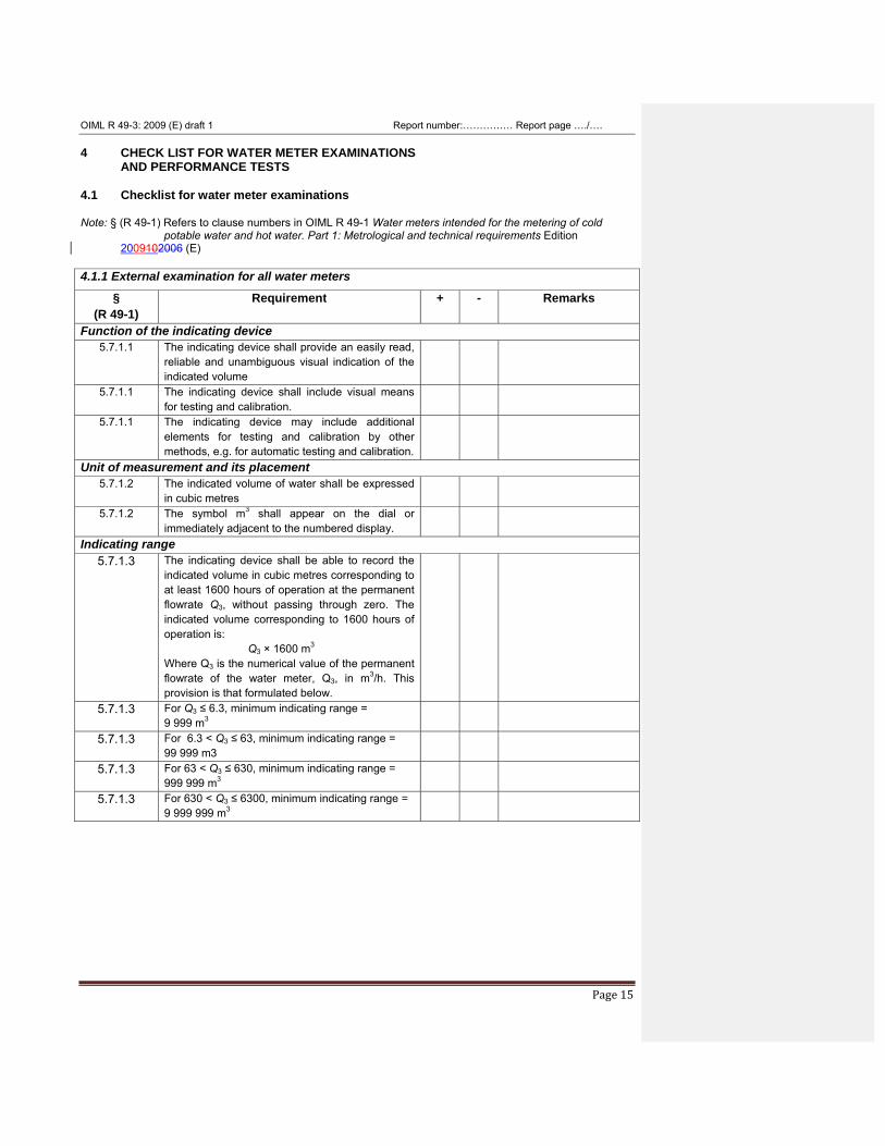
4.1 Checklist for water meter examinations Note: § (R 49-1) Refers to clause numbers in OIML R 49-1 Water meters intended for the metering of cold
potable water and hot water. Part 1: Metrological and technical requirements Edition 2009102006 (E)
4.1.1 External examination for all water meters
§ (R 49-1)
Requirement + - Remarks
Function of the indicating device 5.7.1.1 The indicating device shall provide an easily read,
reliable and unambiguous visual indication of the indicated volume
5.7.1.1 The indicating device shall include visual means for testing and calibration.
5.7.1.1 The indicating device may include additional elements for testing and calibration by other methods, e.g. for automatic testing and calibration.
Unit of measurement and its placement 5.7.1.2 The indicated volume of water shall be expressed
in cubic metres
5.7.1.2 The symbol m3 shall appear on the dial or immediately adjacent to the numbered display.
Indicating range 5.7.1.3 The indicating device shall be able to record the
indicated volume in cubic metres corresponding to at least 1600 hours of operation at the permanent flowrate Q3, without passing through zero. The indicated volume corresponding to 1600 hours of operation is: Q3 × 1600 m3 Where Q3 is the numerical value of the permanent flowrate of the water meter, Q3, in m3/h. This provision is that formulated below.
5.7.1.3 For Q3 ≤ 6.3, minimum indicating range = 9 999 m3
5.7.1.3 For 6.3 < Q3 ≤ 63, minimum indicating range = 99 999 m3
5.7.1.3 For 63 < Q3 ≤ 630, minimum indicating range = 999 999 m3
5.7.1.3 For 630 < Q3 ≤ 6300, minimum indicating range = 9 999 999 m3
OIML R 49-3: 2009 (E) draft 1 Report number:…………… Report page …./….
Page 16
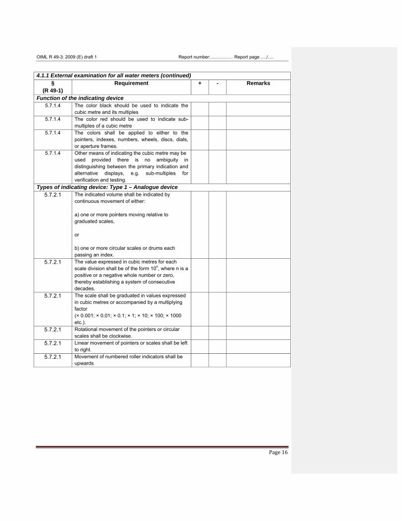
4.1.1 External examination for all water meters (continued)
§ (R 49-1)
Requirement + - Remarks
Function of the indicating device 5.7.1.4 The color black should be used to indicate the
cubic metre and its multiples
5.7.1.4 The color red should be used to indicate sub-multiples of a cubic metre
5.7.1.4 The colors shall be applied to either to the pointers, indexes, numbers, wheels, discs, dials, or aperture frames.
5.7.1.4 Other means of indicating the cubic metre may be used provided there is no ambiguity in distinguishing between the primary indication and alternative displays, e.g. sub-multiples for verification and testing.
Types of indicating device: Type 1 – Analogue device 5.7.2.1 The indicated volume shall be indicated by
continuous movement of either: a) one or more pointers moving relative to graduated scales, or b) one or more circular scales or drums each passing an index.
5.7.2.1 The value expressed in cubic metres for each scale division shall be of the form 10n, where n is a positive or a negative whole number or zero, thereby establishing a system of consecutive decades.
5.7.2.1 The scale shall be graduated in values expressed in cubic metres or accompanied by a multiplying factor (× 0.001; × 0.01; × 0.1; × 1; × 10; × 100; × 1000 etc.).
5.7.2.1 Rotational movement of the pointers or circular scales shall be clockwise.
5.7.2.1 Linear movement of pointers or scales shall be left to right.
5.7.2.1 Movement of numbered roller indicators shall be upwards
OIML R 49-3: 2009 (E) draft 1 Report number:…………… Report page …./….
Page 17
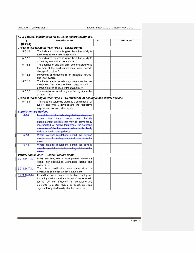
4.1.1 External examination for all water meters (continued)
§ (R 49-1)
Requirement + - Remarks
Types of indicating device: Type 2 – Digital device 5.7.2.2 The indicated volume is given by a line of digits
appearing in one or more apertures.
5.7.2.2 The indicated volume is given by a line of digits appearing in one or more apertures.
5.7.2.2 The advance of one digit shall be completed while the digit of the next immediately lower decade changes from 9 to 0.
5.7.2.2 Movement of numbered roller indicators (drums) shall be upwards.
5.7.2.2 The lowest value decade may have a continuous movement, the aperture being large enough to permit a digit to be read without ambiguity.
5.7.2.2 The actual or apparent height of the digits shall be at least 4 mm.
Types of indicating device: Type 3 – Combination of analogue and digital devices 5.7.2.3 The indicated volume is given by a combination of
type 1 and type 2 devices and the respective requirements of each shall apply.
Supplementary devices 5.7.3 In addition to the indicating devices described
above, the water meter may include supplementary devices that may be permanently incorporated or added temporarily for detecting movement of the flow sensor before this is clearly visible on the indicating device
5.7.3 Where national regulations permit the devices may be used for testing or verification of the water meter.
5.7.3 Where national regulations permit the devices may be used for remote reading of the water meter.
Verification devices – General requirements 5.7.3.15.7.4.1 Every indicating device shall provide means for
visual, non-ambiguous verification testing and calibration.
5.7.3.15.7.4.1 The visual verification may have either a continuous or a discontinuous movement
5.7.3.15.7.4.1 In addition to the visual verification display, an indicating device may include provisions for rapid testing by the inclusion of complementary elements (e.g. star wheels or discs), providing signals through externally attached sensors.
OIML R 49-3: 2009 (E) draft 1 Report number:…………… Report page …./….
Page 18
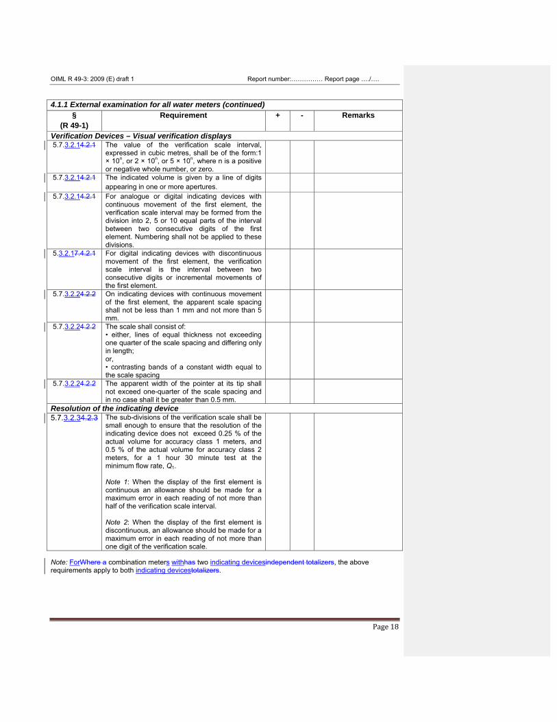
4.1.1 External examination for all water meters (continued)
§ (R 49-1)
Requirement + - Remarks
Verification Devices – Visual verification displays 5.7.3.2.14.2.1 The value of the verification scale interval,
expressed in cubic metres, shall be of the form:1 × 10n, or 2 × 10n, or 5 × 10n, where n is a positive or negative whole number, or zero.
5.7.3.2.14.2.1 The indicated volume is given by a line of digits appearing in one or more apertures.
5.7.3.2.14.2.1 For analogue or digital indicating devices with continuous movement of the first element, the verification scale interval may be formed from the division into 2, 5 or 10 equal parts of the interval between two consecutive digits of the first element. Numbering shall not be applied to these divisions.
5.3.2.17.4.2.1 For digital indicating devices with discontinuous movement of the first element, the verification scale interval is the interval between two consecutive digits or incremental movements of the first element.
5.7.3.2.24.2.2 On indicating devices with continuous movement of the first element, the apparent scale spacing shall not be less than 1 mm and not more than 5 mm.
5.7.3.2.24.2.2 The scale shall consist of: • either, lines of equal thickness not exceeding one quarter of the scale spacing and differing only in length; or, • contrasting bands of a constant width equal to the scale spacing
5.7.3.2.24.2.2 The apparent width of the pointer at its tip shall not exceed one-quarter of the scale spacing and in no case shall it be greater than 0.5 mm.
Resolution of the indicating device 5.7.3.2.34.2.3 The sub-divisions of the verification scale shall be
small enough to ensure that the resolution of the indicating device does not exceed 0.25 % of the actual volume for accuracy class 1 meters, and 0.5 % of the actual volume for accuracy class 2 meters, for a 1 hour 30 minute test at the minimum flow rate, Q1. Note 1: When the display of the first element is continuous an allowance should be made for a maximum error in each reading of not more than half of the verification scale interval. Note 2: When the display of the first element is discontinuous, an allowance should be made for a maximum error in each reading of not more than one digit of the verification scale.
Note: ForWhere a combination meters withhas two indicating devicesindependent totalizers, the above requirements apply to both indicating devicestotalizers.
OIML R 49-3: 2009 (E) draft 1 Report number:…………… Report page …./….
Page 19
4.1.1 External examination for all water meters (continued)
§ (R 49-1)
Requirement + - Remarks
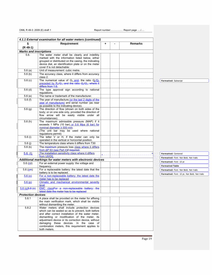
Marks and inscriptions 5.6. The water meter shall be clearly and indelibly
marked with the information listed below, either grouped or distributed on the casing, the indicating device dial, an identification plate or on the meter cover if is not detachable:
5.6 (a) Unit of measurement: cubic metre. 5.6 (b) The accuracy class, where it differs from accuracy
class 2.
5.6 (c) The numerical value of Q3 and, the ratio Q1/Q3 preceded by R3/Q1, and the ratio Q2/Q1, where it differs from 1.6.
5.6 (d) The type approval sign according to national regulations.
5.6 (e) The name or trademark of the manufacturer. 5.6 (f) The year of manufacture (or the last 2 digits of the
year of manufacture) and serial number (as near as possible to the indicating device).
5.6 (g) The direction of flow (shown on both sides of the body; or on one side only, provided the direction of flow arrow will be easily visible under all circumstances).
5.6 (h) The maximum admissible pressure (MAP) if it exceeds 1 MPa (10 bar) or 0.6 Mpa (6 bar) for nominal diameter ≥ 500 mm. (The unit bar may be used where national regulations permit)
5.6 (i) The letter V or H, if the meter can only be operated in the vertical or horizontal position.
5.6 (j) The temperature class where it differs from T30 5.6 (k) The maximum pressure loss class where it differs
from ΔP 63 (see Part 4)if required.
5.6. (l) The installation sensitivity class where it differs from U0/D0
Additional markings for water meters with electronic devices 5.6 (ml) For an external power supply: the voltage and
frequency.
5.6 (nm) For a replaceable battery: the latest date that the battery is to be replaced.
5.6 (o) For a non-replaceable battery: the latest date the meter has to be replaced
5.6 (p) Climatic and mechanical environmental severity level
5.6 (q)5.6 (n) EMC classFor a non-replaceable battery: the latest date the meter has to be replaced
Protection devices 5.8.1 A place shall be provided on the meter for affixing
the main verification mark, which shall be visible without dismantling the meter.
5.8.2 Water meters shall include protection devices which can be sealed so as to prevent, both before and after correct installation of the water meter, dismantling or modification of the meter, its adjustment device or its correction device, without damaging these devices. In the case of combination meters, this requirement applies to both meters.
Formatted: Subscript
Formatted: Centered
Formatted Table
Formatted: Font: Not Bold, Not Italic
Formatted: Font: 10 pt
Formatted: Font: 10 pt, Not Bold, Not Italic
Formatted: Font: Not Bold, Not Italic
OIML R 49-3: 2009 (E) draft 1 Report number:…………… Report page …./….
Page 20
4.1.2 Examination of checking facilities for electronic water meters and mechanical water meters with electronic devices
§ (R 49-1)
Requirement + - Remarks
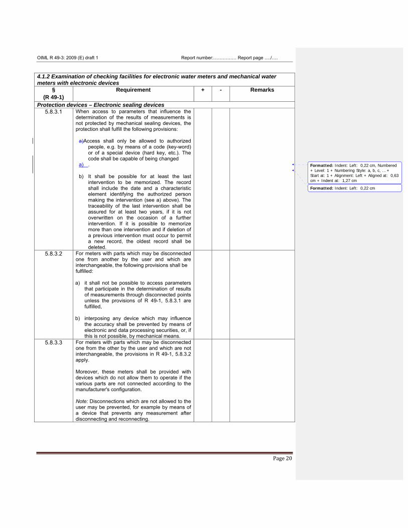
Protection devices – Electronic sealing devices 5.8.3.1 When access to parameters that influence the
determination of the results of measurements is not protected by mechanical sealing devices, the protection shall fulfill the following provisions:
a)Access shall only be allowed to authorized people, e.g. by means of a code (key-word) or of a special device (hard key, etc.). The code shall be capable of being changed
a) . b) It shall be possible for at least the last
intervention to be memorized. The record shall include the date and a characteristic element identifying the authorized person making the intervention (see a) above). The traceability of the last intervention shall be assured for at least two years, if it is not overwritten on the occasion of a further intervention. If it is possible to memorize more than one intervention and if deletion of a previous intervention must occur to permit a new record, the oldest record shall be deleted.
5.8.3.2 For meters with parts which may be disconnected one from another by the user and which are interchangeable, the following provisions shall be fulfilled: a) it shall not be possible to access parameters
that participate in the determination of results of measurements through disconnected points unless the provisions of R 49-1, 5.8.3.1 are fulfilled,
b) interposing any device which may influence the accuracy shall be prevented by means of electronic and data processing securities, or, if this is not possible, by mechanical means.
5.8.3.3 For meters with parts which may be disconnected one from the other by the user and which are not interchangeable, the provisions in R 49-1, 5.8.3.2 apply. Moreover, these meters shall be provided with devices which do not allow them to operate if the various parts are not connected according to the manufacturer's configuration. Note: Disconnections which are not allowed to the user may be prevented, for example by means of a device that prevents any measurement after disconnecting and reconnecting.
Formatted: Indent: Left: 0,22 cm, Numbered+ Level: 1 + Numbering Style: a, b, c, … +Start at: 1 + Alignment: Left + Aligned at: 0,63cm + Indent at: 1,27 cm
Formatted: Indent: Left: 0,22 cm
OIML R 49-3: 2009 (E) draft 1 Report number:…………… Report page …./….
Page 21
4.1.2 Examination of checking facilities for electronic water meters and mechanical water meters with electronic devices (continued)
§ (R 49-1)
Requirement + - Remarks
Examination and testing of checking facilities General requirements for examining checking facilities
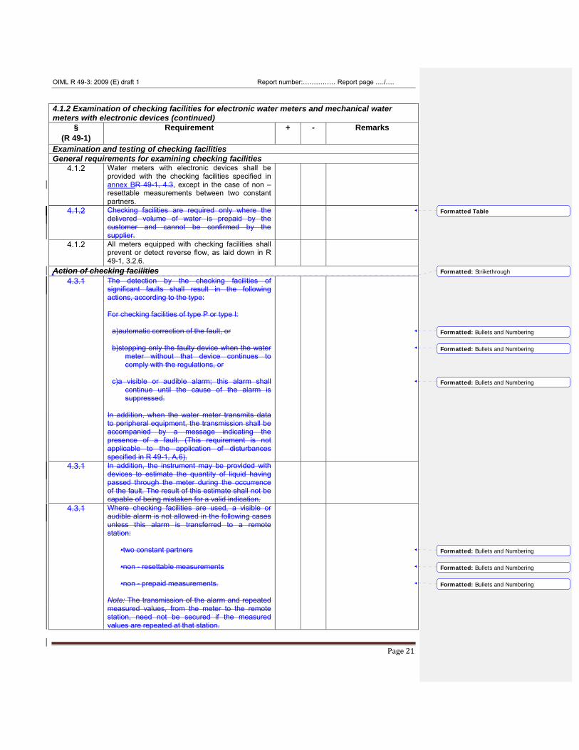
4.1.2 Water meters with electronic devices shall be provided with the checking facilities specified in annex BR 49-1, 4.3, except in the case of non – resettable measurements between two constant partners.
4.1.2 Checking facilities are required only where the delivered volume of water is prepaid by the customer and cannot be confirmed by the supplier.
4.1.2 All meters equipped with checking facilities shall prevent or detect reverse flow, as laid down in R 49-1, 3.2.6.
Action of checking facilities 4.3.1 The detection by the checking facilities of
significant faults shall result in the following actions, according to the type: For checking facilities of type P or type I:
a)automatic correction of the fault, or
b)stopping only the faulty device when the water meter without that device continues to comply with the regulations, or
c)a visible or audible alarm; this alarm shall continue until the cause of the alarm is suppressed.
In addition, when the water meter transmits data to peripheral equipment, the transmission shall be accompanied by a message indicating the presence of a fault. (This requirement is not applicable to the application of disturbances specified in R 49-1, A.6).
4.3.1 In addition, the instrument may be provided with devices to estimate the quantity of liquid having passed through the meter during the occurrence of the fault. The result of this estimate shall not be capable of being mistaken for a valid indication.
4.3.1 Where checking facilities are used, a visible or audible alarm is not allowed in the following cases unless this alarm is transferred to a remote station:
•two constant partners
•non - resettable measurements
•non - prepaid measurements.
Note: The transmission of the alarm and repeated measured values, from the meter to the remote station, need not be secured if the measured values are repeated at that station.
Formatted Table
Formatted: Strikethrough
Formatted: Bullets and Numbering
Formatted: Bullets and Numbering
Formatted: Bullets and Numbering
Formatted: Bullets and Numbering
Formatted: Bullets and Numbering
Formatted: Bullets and Numbering
OIML R 49-3: 2009 (E) draft 1 Report number:…………… Report page …./….
Page 22
4.1.2 Examination of checking facilities for electronic water meters and mechanical water meters with electronic devices (continued)
§ (R 49-1)
Requirement + - Remarks
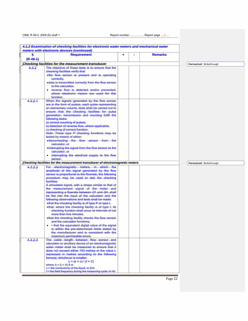
Checking facilities for the measurement transducer 4.3.2 The objective of these tests is to ensure that the
checking facilities verify that: •the flow sensor is present and is operating
correctly, •data is transmitted correctly from the flow sensor
to the calculator, • reverse flow is detected and/or prevented,
where electronic means are used for this function.
4.3.2.1 When the signals generated by the flow sensor are in the form of pulses, each pulse representing an elementary volume, tests shall be carried out to ensure that the checking facilities for pulse generation, transmission and counting fulfill the following tasks: a) correct counting of pulses, b) detection of reverse flow, where applicable, c) checking of correct function. Note: These type P checking functions may be tested by means of either: •disconnecting the flow sensor from the
calculator, or •interrupting the signal from the flow sensor to the
calculator, or • interrupting the electrical supply to the flow
sensor.
Checking facilities for the measurement transducer of electromagnetic meters 4.3.2.2 For electromagnetic meters, in which the
amplitude of the signal generated by the flow sensor is proportional to the flowrate, the following procedure may be used to test the checking facilities: A simulated signal, with a shape similar to that of the measurement signal of the meter and representing a flowrate between Q1 and Q4, shall be fed into the input of the calculator and the following observations and tests shall be made: •that the checking facility is of type P or type I, •that, where the checking facility is of type I, its
checking function shall occur at intervals of not more than five minutes,
•that the checking facility checks the flow sensor and the calculator functions,
• • that the equivalent digital value of the signal is within the pre-determined limits stated by the manufacturer and is consistent with the maximum permissible errors.
4.3.2.3 The cable length between flow sensor and calculator or ancillary device of an electromagnetic water meter shall be measured to ensure that it does not exceed either 100 metres or the value L expressed in metres according to the following formula, whichever is smaller:
L = (k × c) / (f × C) where: k = 2 × 10⁻⁵ m c = the conductivity of the liquid, in S/m f = the field frequency during the measuring cycle, in Hz
Formatted: Strikethrough
Formatted: Strikethrough
OIML R 49-3: 2009 (E) draft 1 Report number:…………… Report page …./….
Page 23
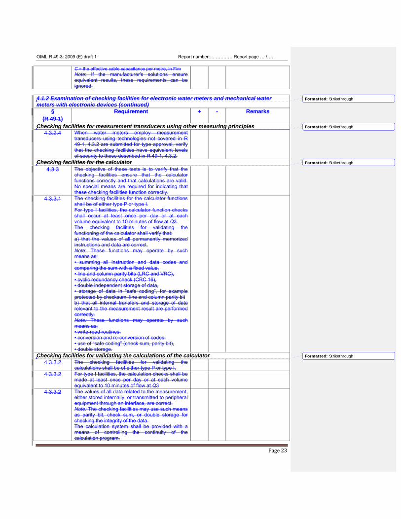
C = the effective cable capacitance per metre, in F/m Note: If the manufacturer's solutions ensure equivalent results, these requirements can be ignored.
4.1.2 Examination of checking facilities for electronic water meters and mechanical water meters with electronic devices (continued)
§ (R 49-1)
Requirement + - Remarks
Checking facilities for measurement transducers using other measuring principles 4.3.2.4 When water meters employ measurement
transducers using technologies not covered in R 49-1, 4.3.2 are submitted for type approval, verify that the checking facilities have equivalent levels of security to those described in R 49-1, 4.3.2.
Checking facilities for the calculator 4.3.3 The objective of these tests is to verify that the
checking facilities ensure that the calculator functions correctly and that calculations are valid. No special means are required for indicating that these checking facilities function correctly.
4.3.3.1 The checking facilities for the calculator functions shall be of either type P or type I. For type I facilities, the calculator function checks shall occur at least once per day or at each volume equivalent to 10 minutes of flow at Q3. The checking facilities for validating the functioning of the calculator shall verify that: a) that the values of all permanently memorized instructions and data are correct. Note: These functions may operate by such means as: • summing all instruction and data codes and comparing the sum with a fixed value, • line and column parity bits (LRC and VRC), • cyclic redundancy check (CRC 16), • double independent storage of data, • storage of data in “safe coding”, for example protected by checksum, line and column parity bit b) that all internal transfers and storage of data relevant to the measurement result are performed correctly. Note: These functions may operate by such means as: • write-read routines, • conversion and re-conversion of codes, • use of “safe coding” (check sum, parity bit), • double storage.
Checking facilities for validating the calculations of the calculator 4.3.3.2 The checking facilities for validating the
calculations shall be of either type P or type I.
4.3.3.2 For type I facilities, the calculation checks shall be made at least once per day or at each volume equivalent to 10 minutes of flow at Q3
4.3.3.2 The values of all data related to the measurement, either stored internally, or transmitted to peripheral equipment through an interface, are correct. Note: The checking facilities may use such means as parity bit, check sum, or double storage for checking the integrity of the data. The calculation system shall be provided with a means of controlling the continuity of the calculation program.
Formatted: Strikethrough
Formatted: Strikethrough
Formatted: Strikethrough
Formatted: Strikethrough
OIML R 49-3: 2009 (E) draft 1 Report number:…………… Report page …./….
Page 24
4.1.2 Examination of checking facilities for electronic water meters and mechanical water meters with electronic devices (continued)
§ (R 49-1)
Requirement + - Remarks
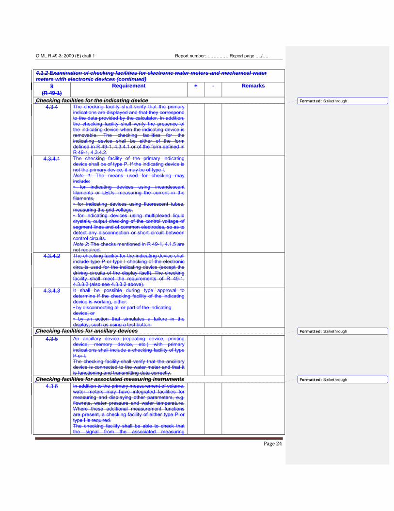
Checking facilities for the indicating device 4.3.4 The checking facility shall verify that the primary
indications are displayed and that they correspond to the data provided by the calculator. In addition, the checking facility shall verify the presence of the indicating device when the indicating device is removable. The checking facilities for the indicating device shall be either of the form defined in R 49-1, 4.3.4.1 or of the form defined in R 49-1, 4.3.4.2.
4.3.4.1 The checking facility of the primary indicating device shall be of type P. If the indicating device is not the primary device, it may be of type I. Note 1: The means used for checking may include: • for indicating devices using incandescent filaments or LEDs, measuring the current in the filaments, • for indicating devices using fluorescent tubes, measuring the grid voltage, • for indicating devices using multiplexed liquid crystals, output checking of the control voltage of segment lines and of common electrodes, so as to detect any disconnection or short circuit between control circuits. Note 2: The checks mentioned in R 49-1, 4.1.5 are not required.
4.3.4.2 The checking facility for the indicating device shall include type P or type I checking of the electronic circuits used for the indicating device (except the driving circuits of the display itself). The checking facility shall meet the requirements of R 49-1, 4.3.3.2 (also see 4.3.3.2 above).
4.3.4.3 It shall be possible during type approval to determine if the checking facility of the indicating device is working, either: • by disconnecting all or part of the indicating device, or • by an action that simulates a failure in the display, such as using a test button.
Checking facilities for ancillary devices 4.3.5 An ancillary device (repeating device, printing
device, memory device, etc.) with primary indications shall include a checking facility of type P or I. The checking facility shall verify that the ancillary device is connected to the water meter and that it is functioning and transmitting data correctly.
Checking facilities for associated measuring instruments 4.3.6 In addition to the primary measurement of volume,
water meters may have integrated facilities for measuring and displaying other parameters, e.g. flowrate, water pressure and water temperature. Where these additional measurement functions are present, a checking facility of either type P or type I is required. The checking facility shall be able to check that the signal from the associated measuring
Formatted: Strikethrough
Formatted: Strikethrough
Formatted: Strikethrough
OIML R 49-3: 2009 (E) draft 1 Report number:…………… Report page …./….
Page 25
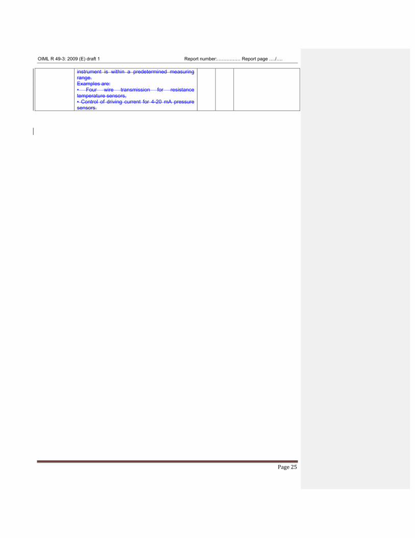
instrument is within a predetermined measuring range. Examples are: • Four wire transmission for resistance temperature sensors, • Control of driving current for 4-20 mA pressure sensors.
OIML R 49-3: 2009 (E) draft 1 Report number:…………… Report page …./….
Page 26
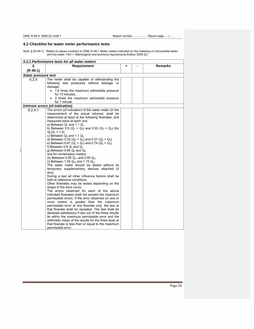
4.2 Checklist for water meter performance tests Note: § (R 49-1) Refers to clause numbers in OIML R 49-1 Water meters intended for the metering of cold potable water
and hot water. Part 1: Metrological and technical requirements Edition 2009 (E) 4.2.1 Performance tests for all water meters
§ (R 49-1)
Requirement + - Remarks
Static pressure test 6.2.5 The meter shall be capable of withstanding the
following test pressures without leakage or damage: • 1.6 times the maximum admissible pressure
for 15 minutes, • 2 times the maximum admissible pressure
for 1 minute.
Intrinsic errors (of indication) 6.2.4.1 The errors (of indication) of the water meter (in the
measurement of the actual volume), shall be determined at least at the following flowrates, and measured twice at each one: a) Between Q1 and 1.1 Q1 b) Between 0.5 (Q1 + Q2) and 0.55 (Q1 + Q2) (for Q2/Q1 > 1.6) c) Between Q2 and 1.1 Q2 d) Between 0.33 (Q2 + Q3) and 0.37 (Q2 + Q3) e) Between 0.67 (Q2 + Q3) and 0.74 (Q2 + Q3) f) Between 0.9 Q3 and Q3 g) Between 0.95 Q4 and Q4 and for combination meters: (h) Between 0.85 Qx1 and 0.95 Qx1 (i) Between 1.05 Qx2 and 1.15 Qx2 The water meter should be tested without its temporary supplementary devices attached (if any). During a test all other influence factors shall be held at reference conditions. Other flowrates may be tested depending on the shape of the error curve. The errors observed for each of the above indicated flowrates shall not exceed the maximum permissible errors. If the error observed on one or more meters is greater than the maximum permissible error at one flowrate only, the test at that flowrate shall be repeated. The test shall be declared satisfactory if two out of the three results lie within the maximum permissible error and the arithmetic mean of the results for the three tests at that flowrate is less than or equal to the maximum permissible error.
OIML R 49-3: 2009 (E) draft 1 Report number:…………… Report page …./….
Page 27
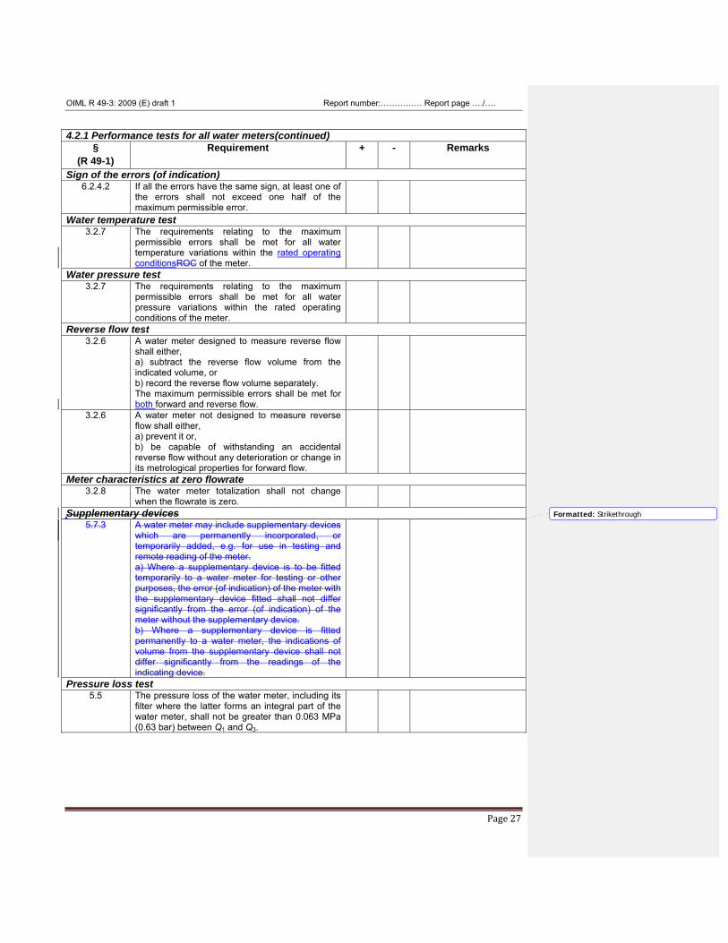
4.2.1 Performance tests for all water meters(continued)
§ (R 49-1)
Requirement + - Remarks
Sign of the errors (of indication) 6.2.4.2 If all the errors have the same sign, at least one of
the errors shall not exceed one half of the maximum permissible error.
Water temperature test 3.2.7 The requirements relating to the maximum
permissible errors shall be met for all water temperature variations within the rated operating conditionsROC of the meter.
Water pressure test 3.2.7 The requirements relating to the maximum
permissible errors shall be met for all water pressure variations within the rated operating conditions of the meter.
Reverse flow test 3.2.6 A water meter designed to measure reverse flow
shall either, a) subtract the reverse flow volume from the indicated volume, or b) record the reverse flow volume separately. The maximum permissible errors shall be met for both forward and reverse flow.
3.2.6 A water meter not designed to measure reverse flow shall either, a) prevent it or, b) be capable of withstanding an accidental reverse flow without any deterioration or change in its metrological properties for forward flow.
Meter characteristics at zero flowrate 3.2.8 The water meter totalization shall not change
when the flowrate is zero.
Supplementary devices 5.7.3 A water meter may include supplementary devices
which are permanently incorporated, or temporarily added, e.g. for use in testing and remote reading of the meter. a) Where a supplementary device is to be fitted temporarily to a water meter for testing or other purposes, the error (of indication) of the meter with the supplementary device fitted shall not differ significantly from the error (of indication) of the meter without the supplementary device. b) Where a supplementary device is fitted permanently to a water meter, the indications of volume from the supplementary device shall not differ significantly from the readings of the indicating device.
Pressure loss test 5.5
The pressure loss of the water meter, including its filter where the latter forms an integral part of the water meter, shall not be greater than 0.063 MPa (0.63 bar) between Q1 and Q3.
Formatted: Strikethrough
OIML R 49-3: 2009 (E) draft 1 Report number:…………… Report page …./….
Page 28
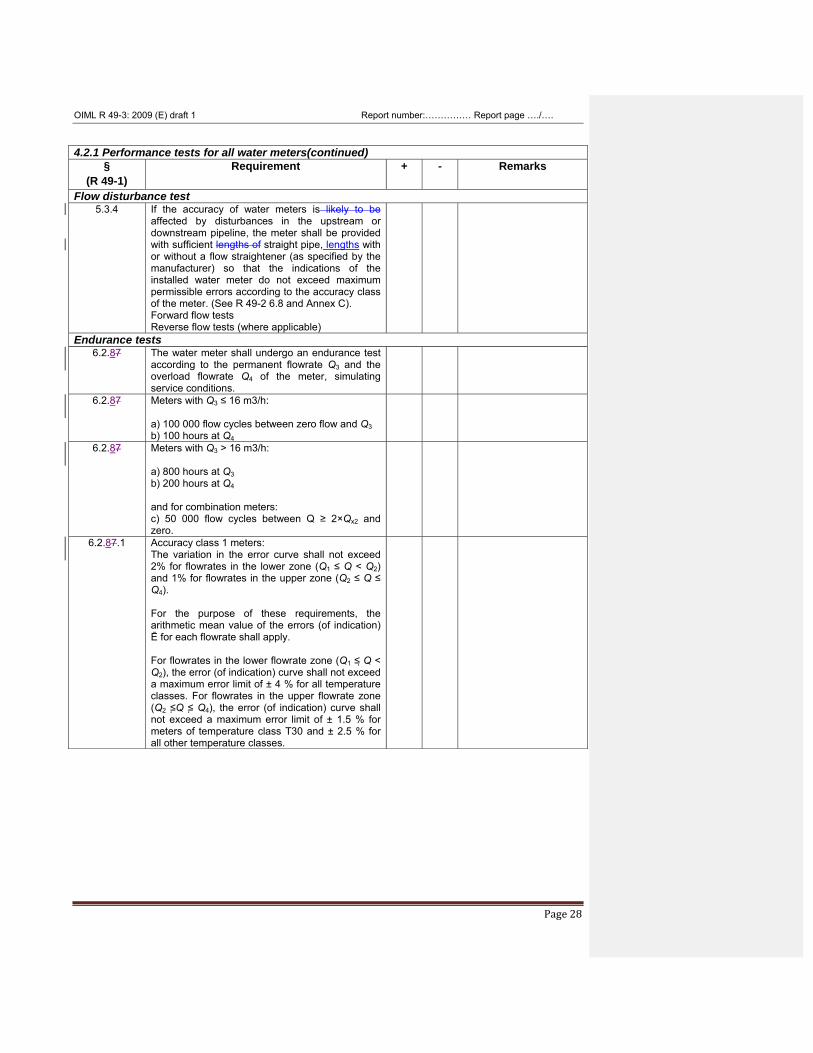
4.2.1 Performance tests for all water meters(continued)
§ (R 49-1)
Requirement + - Remarks
Flow disturbance test 5.3.4 If the accuracy of water meters is likely to be
affected by disturbances in the upstream or downstream pipeline, the meter shall be provided with sufficient lengths of straight pipe, lengths with or without a flow straightener (as specified by the manufacturer) so that the indications of the installed water meter do not exceed maximum permissible errors according to the accuracy class of the meter. (See R 49-2 6.8 and Annex C). Forward flow tests Reverse flow tests (where applicable)
Endurance tests 6.2.87 The water meter shall undergo an endurance test
according to the permanent flowrate Q3 and the overload flowrate Q4 of the meter, simulating service conditions.
6.2.87 Meters with Q3 ≤ 16 m3/h: a) 100 000 flow cycles between zero flow and Q3 b) 100 hours at Q4
6.2.87 Meters with Q3 > 16 m3/h: a) 800 hours at Q3 b) 200 hours at Q4 and for combination meters: c) 50 000 flow cycles between Q ≥ 2×Qx2 and zero.
6.2.87.1 Accuracy class 1 meters: The variation in the error curve shall not exceed 2% for flowrates in the lower zone (Q1 ≤ Q < Q2) and 1% for flowrates in the upper zone (Q2 ≤ Q ≤ Q4). For the purpose of these requirements, the arithmetic mean value of the errors (of indication) Ē for each flowrate shall apply. For flowrates in the lower flowrate zone (Q1 ≤ Q < Q2), the error (of indication) curve shall not exceed a maximum error limit of ± 4 % for all temperature classes. For flowrates in the upper flowrate zone (Q2 ≤Q ≤ Q4), the error (of indication) curve shall not exceed a maximum error limit of ± 1.5 % for meters of temperature class T30 and ± 2.5 % for all other temperature classes.
OIML R 49-3: 2009 (E) draft 1 Report number:…………… Report page …./….
Page 29
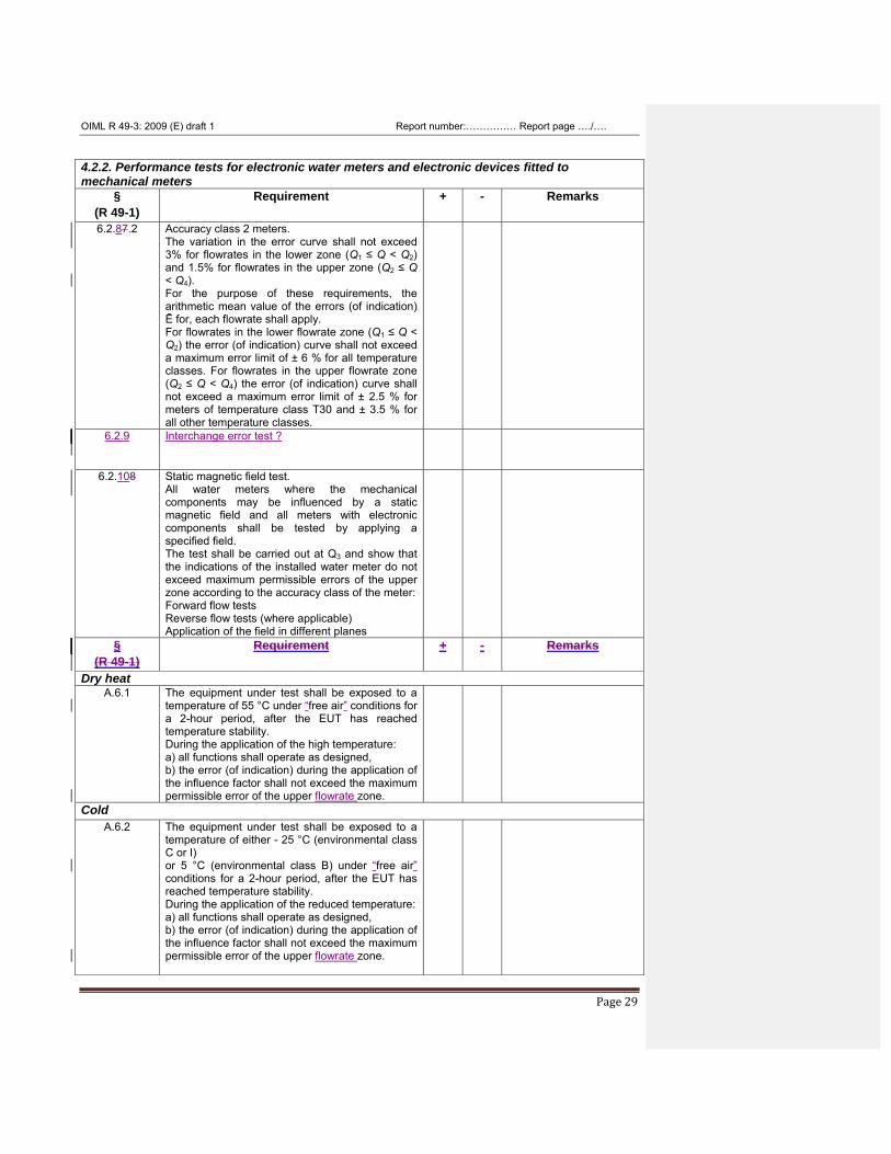
4.2.2. Performance tests for electronic water meters and electronic devices fitted to mechanical meters
§ (R 49-1)
Requirement + - Remarks
6.2.87.2 Accuracy class 2 meters. The variation in the error curve shall not exceed 3% for flowrates in the lower zone (Q1 ≤ Q < Q2) and 1.5% for flowrates in the upper zone (Q2 ≤ Q < Q4). For the purpose of these requirements, the arithmetic mean value of the errors (of indication) Ē for, each flowrate shall apply. For flowrates in the lower flowrate zone (Q1 ≤ Q < Q2) the error (of indication) curve shall not exceed a maximum error limit of ± 6 % for all temperature classes. For flowrates in the upper flowrate zone (Q2 ≤ Q < Q4) the error (of indication) curve shall not exceed a maximum error limit of ± 2.5 % for meters of temperature class T30 and ± 3.5 % for all other temperature classes.
6.2.9 Interchange error test ?
6.2.108 Static magnetic field test. All water meters where the mechanical components may be influenced by a static magnetic field and all meters with electronic components shall be tested by applying a specified field. The test shall be carried out at Q3 and show that the indications of the installed water meter do not exceed maximum permissible errors of the upper zone according to the accuracy class of the meter: Forward flow tests Reverse flow tests (where applicable) Application of the field in different planes
§ (R 49-1)
Requirement + - Remarks
Dry heat A.6.1 The equipment under test shall be exposed to a
temperature of 55 °C under “free air” conditions for a 2-hour period, after the EUT has reached temperature stability. During the application of the high temperature: a) all functions shall operate as designed, b) the error (of indication) during the application of the influence factor shall not exceed the maximum permissible error of the upper flowrate zone.
Cold A.6.2 The equipment under test shall be exposed to a
temperature of either - 25 °C (environmental class C or I) or 5 °C (environmental class B) under “free air” conditions for a 2-hour period, after the EUT has reached temperature stability. During the application of the reduced temperature: a) all functions shall operate as designed, b) the error (of indication) during the application of the influence factor shall not exceed the maximum permissible error of the upper flowrate zone.
OIML R 49-3: 2009 (E) draft 1 Report number:…………… Report page …./….
Page 30
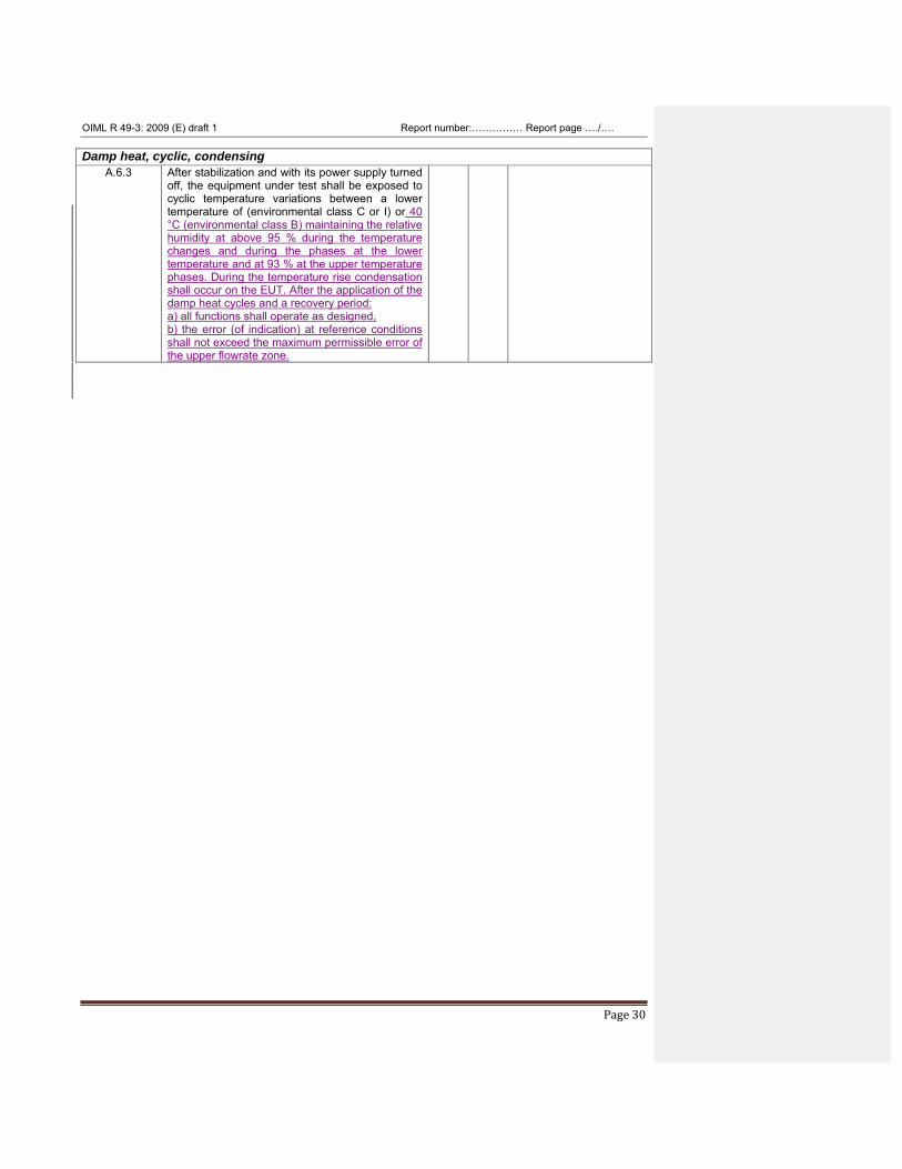
Damp heat, cyclic, condensing A.6.3
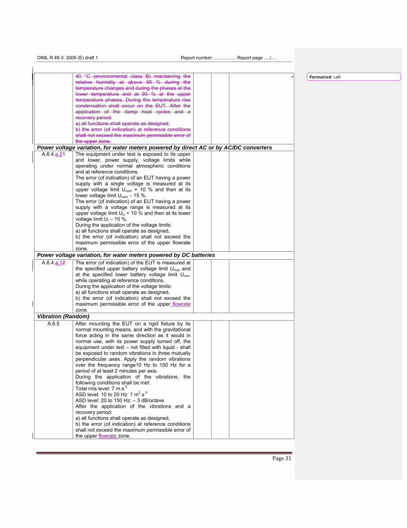
After stabilization and with its power supply turned off, the equipment under test shall be exposed to cyclic temperature variations between a lower temperature of (environmental class C or I) or 40 °C (environmental class B) maintaining the relative humidity at above 95 % during the temperature changes and during the phases at the lower temperature and at 93 % at the upper temperature phases. During the temperature rise condensation shall occur on the EUT. After the application of the damp heat cycles and a recovery period: a) all functions shall operate as designed, b) the error (of indication) at reference conditions shall not exceed the maximum permissible error of the upper flowrate zone.
OIML R 49-3: 2009 (E) draft 1 Report number:…………… Report page …./….
Page 31
40 °C (environmental class B) maintaining the
relative humidity at above 95 % during the temperature changes and during the phases at the lower temperature and at 93 % at the upper temperature phases. During the temperature rise condensation shall occur on the EUT. After the application of the damp heat cycles and a recovery period: a) all functions shall operate as designed, b) the error (of indication) at reference conditions shall not exceed the maximum permissible error of the upper zone.
Power voltage variation, for water meters powered by direct AC or by AC/DC converters A.6.4.a.21 The equipment under test is exposed to its upper
and lower, power supply, voltage limits while operating under normal atmospheric conditions and at reference conditions. The error (of indication) of an EUT having a power supply with a single voltage is measured at its upper voltage limit Unom + 10 % and then at its lower voltage limit Unom – 15 %. The error (of indication) of an EUT having a power supply with a voltage range is measured at its upper voltage limit UU + 10 % and then at its lower voltage limit UI – 15 %. During the application of the voltage limits: a) all functions shall operate as designed, b) the error (of indication) shall not exceed the maximum permissible error of the upper flowrate zone.
Power voltage variation, for water meters powered by DC batteries A.6.4.a.12 The error (of indication) of the EUT is measured at
the specified upper battery voltage limit Umax and at the specified lower battery voltage limit Umin, while operating at reference conditions. During the application of the voltage limits: a) all functions shall operate as designed, b) the error (of indication) shall not exceed the maximum permissible error of the upper flowrate zone.
Vibration (Random) A.6.5
After mounting the EUT on a rigid fixture by its normal mounting means, and with the gravitational force acting in the same direction as it would in normal use, with its power supply turned off, the equipment under test – not filled with liquid - shall be exposed to random vibrations in three mutually perpendicular axes. Apply the random vibrations over the frequency range10 Hz to 150 Hz for a period of at least 2 minutes per axis. During the application of the vibrations, the following conditions shall be met: Total rms level: 7 m.s-2 ASD level: 10 to 20 Hz: 1 m2.s-3 ASD level: 20 to 150 Hz: – 3 dB/octave After the application of the vibrations and a recovery period: a) all functions shall operate as designed, b) the error (of indication) at reference conditions shall not exceed the maximum permissible error of the upper flowrate zone.
Formatted: Left
OIML R 49-3: 2009 (E) draft 1 Report number:…………… Report page …./….
Page 32
4.2.2. Performance tests for electronic water meters and electronic devices fitted to mechanical meters (continued)
§ (R 49-1)
Requirement + - Remarks
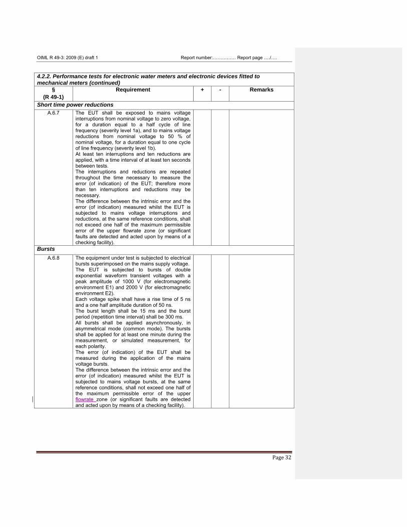
Short time power reductions A.6.7
The EUT shall be exposed to mains voltage interruptions from nominal voltage to zero voltage, for a duration equal to a half cycle of line frequency (severity level 1a), and to mains voltage reductions from nominal voltage to 50 % of nominal voltage, for a duration equal to one cycle of line frequency (severity level 1b). At least ten interruptions and ten reductions are applied, with a time interval of at least ten seconds between tests. The interruptions and reductions are repeated throughout the time necessary to measure the error (of indication) of the EUT; therefore more than ten interruptions and reductions may be necessary. The difference between the intrinsic error and the error (of indication) measured whilst the EUT is subjected to mains voltage interruptions and reductions, at the same reference conditions, shall not exceed one half of the maximum permissible error of the upper flowrate zone (or significant faults are detected and acted upon by means of a checking facility).
Bursts A.6.8 The equipment under test is subjected to electrical
bursts superimposed on the mains supply voltage. The EUT is subjected to bursts of double exponential waveform transient voltages with a peak amplitude of 1000 V (for electromagnetic environment E1) and 2000 V (for electromagnetic environment E2). Each voltage spike shall have a rise time of 5 ns and a one half amplitude duration of 50 ns. The burst length shall be 15 ms and the burst period (repetition time interval) shall be 300 ms. All bursts shall be applied asynchronously, in asymmetrical mode (common mode). The bursts shall be applied for at least one minute during the measurement, or simulated measurement, for each polarity. The error (of indication) of the EUT shall be measured during the application of the mains voltage bursts. The difference between the intrinsic error and the error (of indication) measured whilst the EUT is subjected to mains voltage bursts, at the same reference conditions, shall not exceed one half of the maximum permissible error of the upper flowrate zone (or significant faults are detected and acted upon by means of a checking facility).
OIML R 49-3: 2009 (E) draft 1 Report number:…………… Report page …./….
Page 33
4.2.2. Performance tests for electronic water meters and electronic devices fitted to mechanical meters (continued)
§ (R 49-1)
Requirement + - Remarks
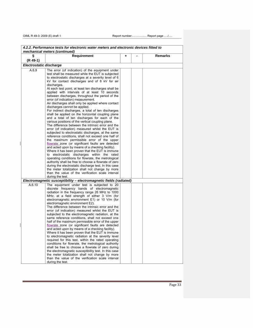
Electrostatic discharge A.6.9 The error (of indication) of the equipment under
test shall be measured while the EUT is subjected to electrostatic discharges at a severity level of 6 kV for contact discharges and of 8 kV for air discharges. At each test point, at least ten discharges shall be applied with intervals of at least 10 seconds between discharges, throughout the period of the error (of indication) measurement. Air discharges shall only be applied where contact discharges cannot be applied. For indirect discharges, a total of ten discharges shall be applied on the horizontal coupling plane and a total of ten discharges for each of the various positions of the vertical coupling plane. The difference between the intrinsic error and the error (of indication) measured whilst the EUT is subjected to electrostatic discharges, at the same reference conditions, shall not exceed one half of the maximum permissible error of the upper flowrate zone (or significant faults are detected and acted upon by means of a checking facility). Where it has been proven that the EUT is immune to electrostatic discharges within the rated operating conditions for flowrate, the metrological authority shall be free to choose a flowrate of zero during the electrostatic discharge test. In this case the meter totalization shall not change by more than the value of the verification scale interval during the test.
Electromagnetic susceptibility – electromagnetic fields (radiated) A.6.10 The equipment under test is subjected to 20
discrete frequency bands of electromagnetic radiation in the frequency range 26 MHz to 1000 MHz, at a field strength of either 3 V/m (for electromagnetic environment E1) or 10 V/m (for electromagnetic environment E2). The difference between the intrinsic error and the error (of indication) measured whilst the EUT is subjected to the electromagnetic radiation, at the same reference conditions, shall not exceed one half of the maximum permissible error of the upper flowrate zone (or significant faults are detected and acted upon by means of a checking facility). Where it has been proven that the EUT is immune to electromagnetic radiation at the severity level required for this test, within the rated operating conditions for flowrate, the metrological authority shall be free to choose a flowrate of zero during the electromagnetic susceptibility test. In this case the meter totalization shall not change by more than the value of the verification scale interval during the test.
OIML R 49-3: 2009 (E) draft 1 Report number:…………… Report page …./….
Page 34
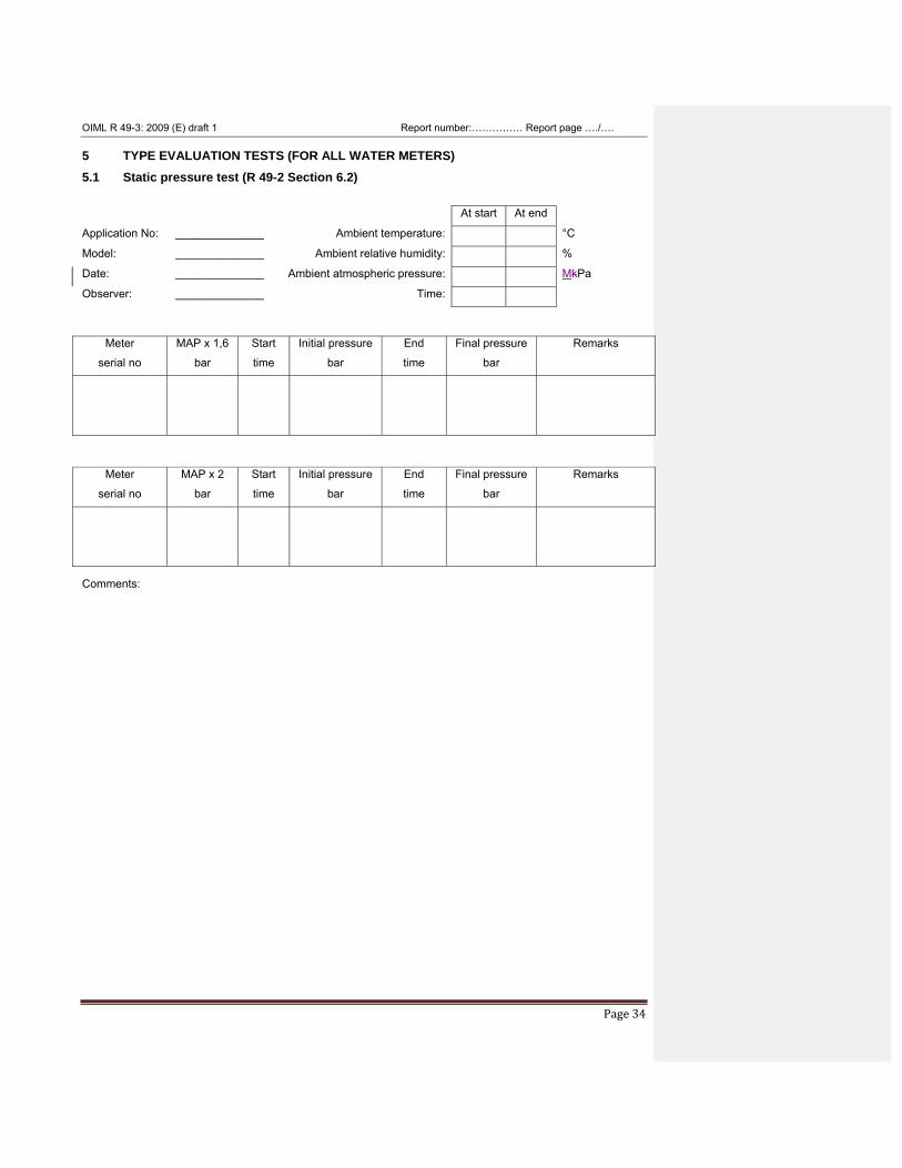
5 TYPE EVALUATION TESTS (FOR ALL WATER METERS) 5.1 Static pressure test (R 49-2 Section 6.2) At start At end
Application No: ______________ Ambient temperature: °C
Model: ______________ Ambient relative humidity: %
Date: ______________ Ambient atmospheric pressure: MkPa
Observer: ______________ Time:
Meter
serial no
MAP x 1,6
bar
Start
time
Initial pressure
bar
End
time
Final pressure
bar
Remarks
Meter
serial no
MAP x 2
bar
Start
time
Initial pressure
bar
End
time
Final pressure
bar
Remarks
Comments:
OIML R 49-3: 2009 (E) draft 1 Report number:…………… Report page …./….
Page 35
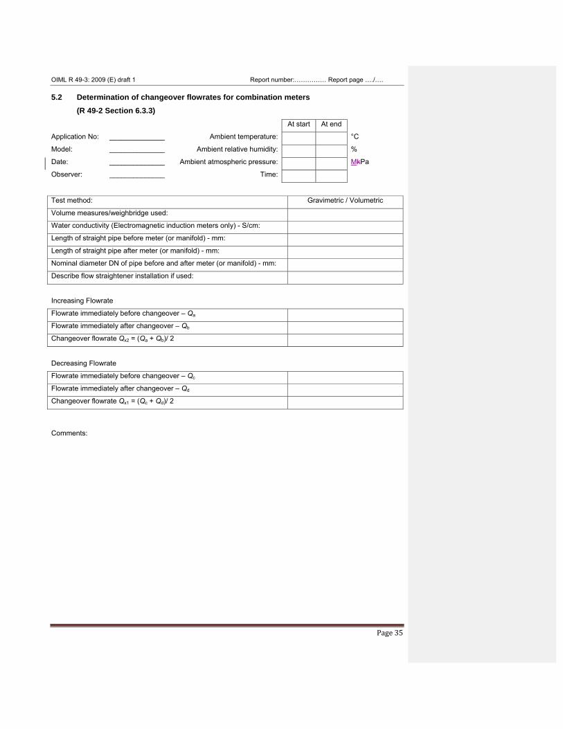
5.2 Determination of changeover flowrates for combination meters (R 49-2 Section 6.3.3)
At start At end
Application No: ______________ Ambient temperature: °C
Model: ______________ Ambient relative humidity: %
Date: ______________ Ambient atmospheric pressure: MkPa
Observer: ______________ Time: Test method: Gravimetric / Volumetric
Volume measures/weighbridge used:
Water conductivity (Electromagnetic induction meters only) - S/cm:
Length of straight pipe before meter (or manifold) - mm:
Length of straight pipe after meter (or manifold) - mm:
Nominal diameter DN of pipe before and after meter (or manifold) - mm:
Describe flow straightener installation if used:
Increasing Flowrate
Flowrate immediately before changeover – Qa
Flowrate immediately after changeover – Qb
Changeover flowrate Qx2 = (Qa + Qb)/ 2
Decreasing Flowrate
Flowrate immediately before changeover – Qc
Flowrate immediately after changeover – Qd
Changeover flowrate Qx1 = (Qc + Qd)/ 2
Comments:
OIML R 49-3: 2009 (E) draft 1 Report number:…………… Report page …./….
Page 36
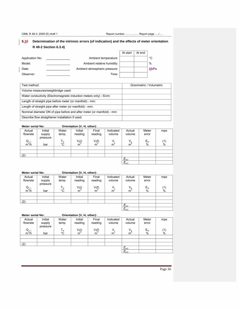
5.32 Determination of the intrinsic errors (of indication) and the effects of meter orientation R 49-2 Section 6.3.4)
At start At end
Application No: ______________ Ambient temperature: °C
Model: ______________ Ambient relative humidity: %
Date: ______________ Ambient atmospheric pressure: MkPa
Observer: ______________ Time: Test method: Gravimetric / Volumetric
Volume measures/weighbridge used:
Water conductivity (Electromagnetic induction meters only) - S/cm:
Length of straight pipe before meter (or manifold) - mm:
Length of straight pipe after meter (or manifold) - mm:
Nominal diameter DN of pipe before and after meter (or manifold) - mm:
Describe flow straightener installation if used:
Meter serial No:__________ Orientation (V, H, other):______________
Actual flowrate
Q ( ) m3/h
Initial supply
pressure
bar
Water temp.
Tw °C
Initial reading
Vi(i) m3
Final reading
Vi(f) m3
Indicated volume
Vi m3
Actual volume
Va m3
Meter error
Em %
mpe
(1) %
(2) Ēm2 Ēm3 Meter serial No:__________ Orientation (V, H, other):______________
Actual flowrate
Q ( ) m3/h
Initial supply
pressure
bar
Water temp.
Tw °C
Initial reading
Vi(i) m3
Final reading
Vi(f) m3
Indicated volume
Vi m3
Actual volume
Va m3
Meter error
Em %
mpe
(1) %
(2) Ēm2 Ēm3 Meter serial No:__________ Orientation (V, H, other):______________
Actual flowrate
Q ( ) m3/h
Initial supply
pressure
bar
Water temp.
Tw °C
Initial reading
Vi(i) m3
Final reading
Vi(f) m3
Indicated volume
Vi m3
Actual volume
Va m3
Meter error
Em %
mpe
(1) %
(2) Ēm2 Ēm3
OIML R 49-3: 2009 (E) draft 1 Report number:…………… Report page …./….
Page 37
Em = The value of the error (of indication) taken at the actual flowrate Q( )
Ēm2 = Mean value of two measurements of the error (of indication) taken at the same nominal flowrate
Ēm3 = Mean value of three measurements of the error (of indication) taken at the same nominal flowrate
(1) For a complete water meter this is the maximum permissible error as defined in R 49-1, section 3.2.1
or3.2.2 according to the accuracy class of the meter. If the EUT is a separable sub-assembly the mpe
shall be defined by the manufacturer (R 49-2, 8.4). For acceptance criteria refer to R 49-2, section
6.3.4.
(2) Perform 3rd test if test 1 or 2 is greater than the mpe (R 49-2, section 6.3.4).
Notes:
1) Tables for each flowrate according to 6.3.4 of R 49-2 shall be added.
2) Tables for each orientation, which shall be as described in 6.3.2.2.7.5 of R 49-2, shall be provided for
meters not marked either ‘H’ or ‘V’.
Comments:
OIML R 49-3: 2009 (E) draft 1 Report number:…………… Report page …./….
Page 38
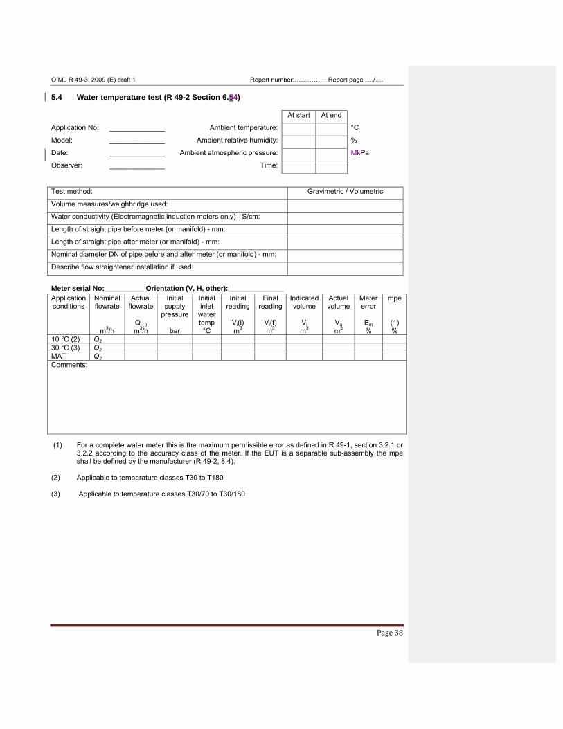
5.4 Water temperature test (R 49-2 Section 6.54) At start At end
Application No: ______________ Ambient temperature: °C
Model: ______________ Ambient relative humidity: %
Date: ______________ Ambient atmospheric pressure: MkPa
Observer: ______________ Time: Test method: Gravimetric / Volumetric
Volume measures/weighbridge used:
Water conductivity (Electromagnetic induction meters only) - S/cm:
Length of straight pipe before meter (or manifold) - mm:
Length of straight pipe after meter (or manifold) - mm:
Nominal diameter DN of pipe before and after meter (or manifold) - mm:
Describe flow straightener installation if used:
Meter serial No:__________ Orientation (V, H, other):______________ Application conditions
Nominal flowrate
m3/h
Actual flowrate
Q ( ) m3/h
Initial supply
pressure
bar
Initial inlet
water temp °C
Initial reading
Vi(i) m3
Final reading
Vi(f) m3
Indicatedvolume
Vi m3
Actual volume
Va m3
Meter error
Em %
mpe
(1) %
10 °C (2) Q2 30 °C (3) Q2 MAT Q2 Comments: (1) For a complete water meter this is the maximum permissible error as defined in R 49-1, section 3.2.1 or
3.2.2 according to the accuracy class of the meter. If the EUT is a separable sub-assembly the mpe shall be defined by the manufacturer (R 49-2, 8.4).
(2) Applicable to temperature classes T30 to T180 (3) Applicable to temperature classes T30/70 to T30/180
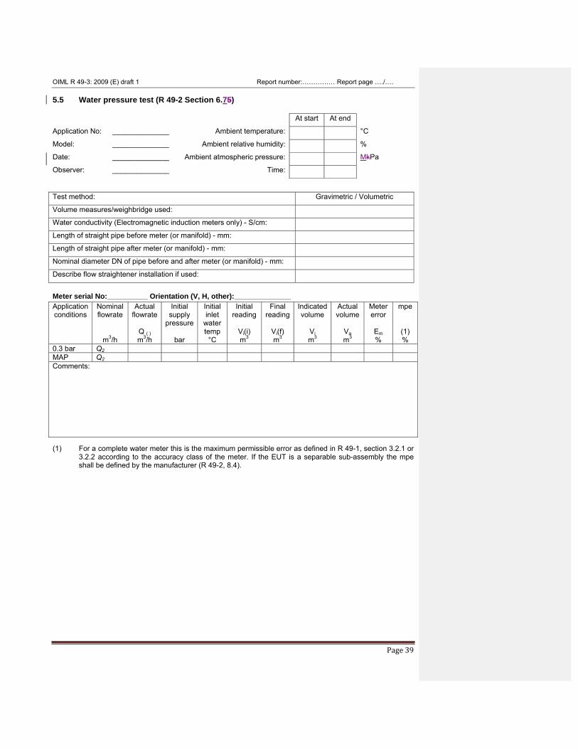
OIML R 49-3: 2009 (E) draft 1 Report number:…………… Report page …./….
Page 39
5.5 Water pressure test (R 49-2 Section 6.75) At start At end
Application No: ______________ Ambient temperature: °C
Model: ______________ Ambient relative humidity: %
Date: ______________ Ambient atmospheric pressure: MkPa
Observer: ______________ Time: Test method: Gravimetric / Volumetric
Volume measures/weighbridge used:
Water conductivity (Electromagnetic induction meters only) - S/cm:
Length of straight pipe before meter (or manifold) - mm:
Length of straight pipe after meter (or manifold) - mm:
Nominal diameter DN of pipe before and after meter (or manifold) - mm:
Describe flow straightener installation if used:
Meter serial No:__________ Orientation (V, H, other):______________ Application conditions
Nominal flowrate
m3/h
Actual flowrate
Q ( ) m3/h
Initial supply
pressure
bar
Initial inlet
water temp °C
Initial reading
Vi(i) m3
Final reading
Vi(f) m3
Indicatedvolume
Vi m3
Actual volume
Va m3
Meter error
Em %
mpe
(1) %
0.3 bar Q2 MAP Q2 Comments: (1) For a complete water meter this is the maximum permissible error as defined in R 49-1, section 3.2.1 or
3.2.2 according to the accuracy class of the meter. If the EUT is a separable sub-assembly the mpe shall be defined by the manufacturer (R 49-2, 8.4).
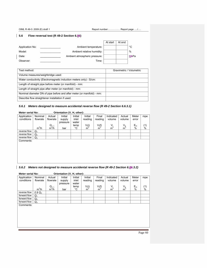
OIML R 49-3: 2009 (E) draft 1 Report number:…………… Report page …./….
Page 40
5.6 Flow reversal test (R 49-2 Section 6.86) At start At end
Application No: ______________ Ambient temperature: °C
Model: ______________ Ambient relative humidity: %
Date: ______________ Ambient atmospheric pressure: MkPa
Observer: ______________ Time: Test method: Gravimetric / Volumetric
Volume measures/weighbridge used:
Water conductivity (Electromagnetic induction meters only) - S/cm:
Length of straight pipe before meter (or manifold) - mm:
Length of straight pipe after meter (or manifold) - mm:
Nominal diameter DN of pipe before and after meter (or manifold) - mm:
Describe flow straightener installation if used:
5.6.1 Meters designed to measure accidental reverse flow (R 49-2 Section 6.6.3.1) Meter serial No:__________ Orientation (V, H, other):______________ Application conditions
Nominal flowrate
m3/h
Actual flowrate
Q ( ) m3/h
Initial supply
pressure
bar
Initial inlet
water temp °C
Initial reading
Vi(i) m3
Final reading
Vi(f) m3
Indicatedvolume
Vi m3
Actual volume
Va m3
Meter error
Em %
mpe
(1) %
reverse flow Q1 reverse flow Q2 reverse flow Q3 Comments: 5.6.2 Meters not designed to measure accidental reverse flow (R 49-2 Section 6.86.3.2) Meter serial No:__________ Orientation (V, H, other):______________ Application conditions
Nominal flowrate
m3/h
Actual flowrate
Q ( ) m3/h
Initial supply
pressure
bar
Initial inlet
water temp °C
Initial reading
Vi(i) m3
Final reading
Vi(f) m3
Indicatedvolume
Vi m3
Actual volume
Va m3
Meter error
Em %
mpe
(1) %
reverse flow 0.9 Q3 forward flow Q1 forward flow Q2 forward flow Q3 Comments:
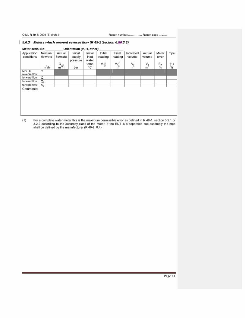
OIML R 49-3: 2009 (E) draft 1 Report number:…………… Report page …./….
Page 41
5.6.3 Meters which prevent reverse flow (R 49-2 Section 6.86.3.3) Meter serial No:__________ Orientation (V, H, other):______________ Application conditions
Nominal flowrate
m3/h
Actual flowrate
Q ( ) m3/h
Initial supply
pressure
bar
Initial inlet
water temp °C
Initial reading
Vi(i) m3
Final reading
Vi(f) m3
Indicatedvolume
Vi m3
Actual volume
Va m3
Meter error
Em %
mpe
(1) %
MAP at reverse flow
0
forward flow Q1 forward flow Q2 forward flow Q3 Comments: (1) For a complete water meter this is the maximum permissible error as defined in R 49-1, section 3.2.1 or
3.2.2 according to the accuracy class of the meter. If the EUT is a separable sub-assembly the mpe shall be defined by the manufacturer (R 49-2, 8.4).
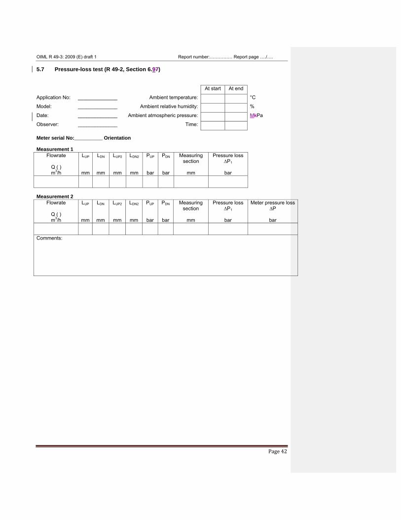
OIML R 49-3: 2009 (E) draft 1 Report number:…………… Report page …./….
Page 42
5.7 Pressure-loss test (R 49-2, Section 6.97) At start At end
Application No: ______________ Ambient temperature: °C
Model: ______________ Ambient relative humidity: %
Date: ______________ Ambient atmospheric pressure: MkPa
Observer: ______________ Time: Meter serial No:__________ Orientation Measurement 1
Flowrate
Q ( ) m3/h
LUP
mm
LDN
mm
LUP2
mm
LDN2
mm
PUP
bar
PDN
bar
Measuring section
mm
Pressure loss ∆P1
bar
Measurement 2
Flowrate
Q ( ) m3/h
LUP
mm
LDN
mm
LUP2
mm
LDN2
mm
PUP
bar
PDN
bar
Measuring section
mm
Pressure loss ∆P1
bar
Meter pressure loss ∆P
bar
Comments:
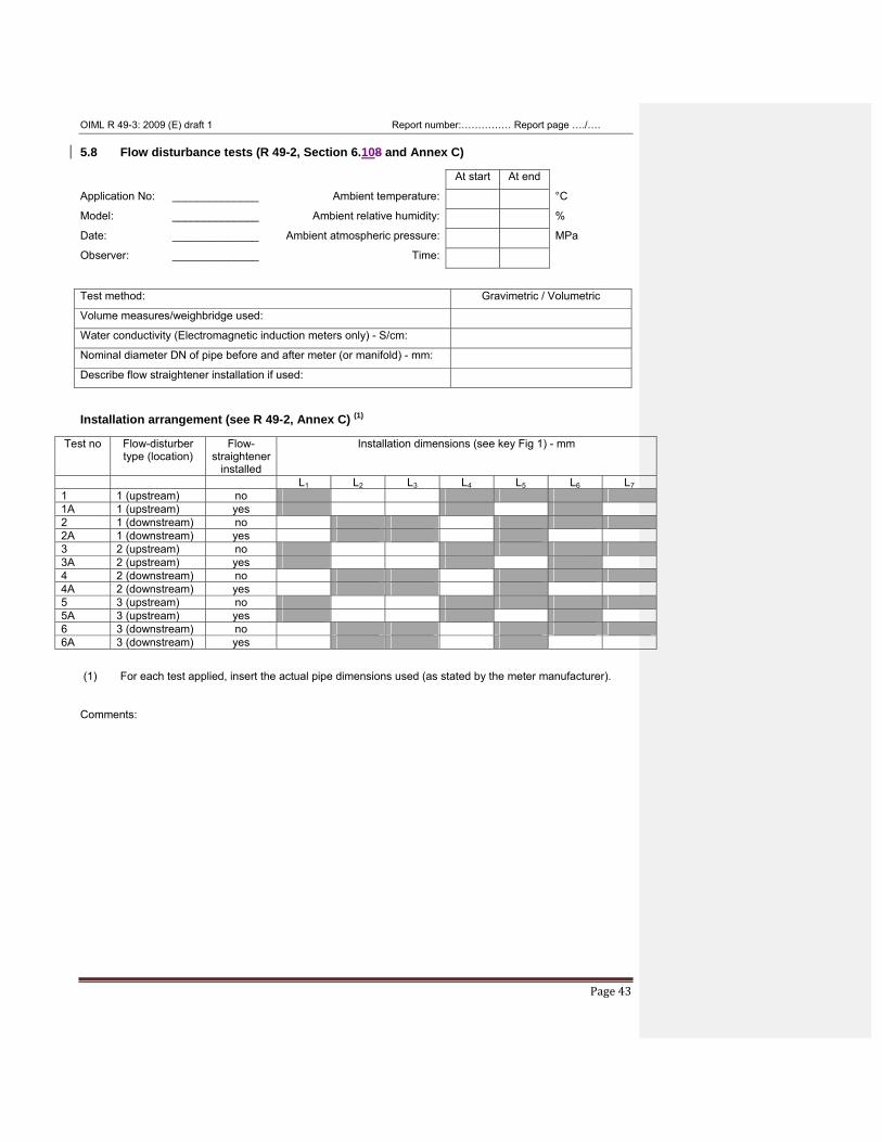
OIML R 49-3: 2009 (E) draft 1 Report number:…………… Report page …./….
Page 43
5.8 Flow disturbance tests (R 49-2, Section 6.108 and Annex C) At start At end
Application No: ______________ Ambient temperature: °C
Model: ______________ Ambient relative humidity: %
Date: ______________ Ambient atmospheric pressure: MPa
Observer: ______________ Time: Test method: Gravimetric / Volumetric
Volume measures/weighbridge used:
Water conductivity (Electromagnetic induction meters only) - S/cm:
Nominal diameter DN of pipe before and after meter (or manifold) - mm:
Describe flow straightener installation if used:
Installation arrangement (see R 49-2, Annex C) (1)
Test no Flow-disturber type (location)
Flow-straightener
installed
Installation dimensions (see key Fig 1) - mm
L1 L2 L3 L4 L5 L6 L7 1 1 (upstream) no 1A 1 (upstream) yes 2 1 (downstream) no 2A 1 (downstream) yes 3 2 (upstream) no 3A 2 (upstream) yes 4 2 (downstream) no 4A 2 (downstream) yes 5 3 (upstream) no 5A 3 (upstream) yes 6 3 (downstream) no 6A 3 (downstream) yes
(1) For each test applied, insert the actual pipe dimensions used (as stated by the meter manufacturer). Comments:
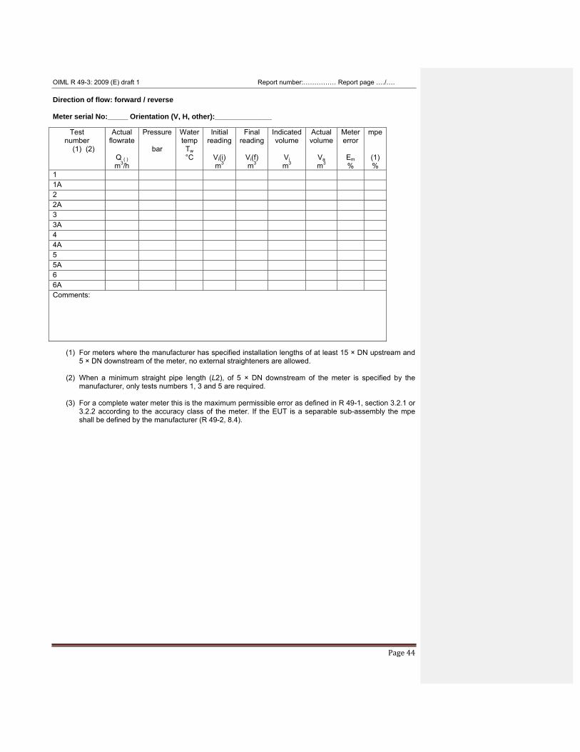
OIML R 49-3: 2009 (E) draft 1 Report number:…………… Report page …./….
Page 44
Direction of flow: forward / reverse Meter serial No:_____ Orientation (V, H, other):______________
Test number
(1) (2)
Actual flowrate
Q ( ) m3/h
Pressure
bar
Water temp
Tw °C
Initial reading
Vi(i) m3
Final reading
Vi(f) m3
Indicatedvolume
Vi m3
Actual volume
Va m3
Metererror
Em %
mpe
(1) %
1 1A 2 2A 3 3A 4 4A 5 5A 6 6A Comments:
(1) For meters where the manufacturer has specified installation lengths of at least 15 × DN upstream and 5 × DN downstream of the meter, no external straighteners are allowed.
(2) When a minimum straight pipe length (L2), of 5 × DN downstream of the meter is specified by the manufacturer, only tests numbers 1, 3 and 5 are required.
(3) For a complete water meter this is the maximum permissible error as defined in R 49-1, section 3.2.1 or
3.2.2 according to the accuracy class of the meter. If the EUT is a separable sub-assembly the mpe shall be defined by the manufacturer (R 49-2, 8.4).
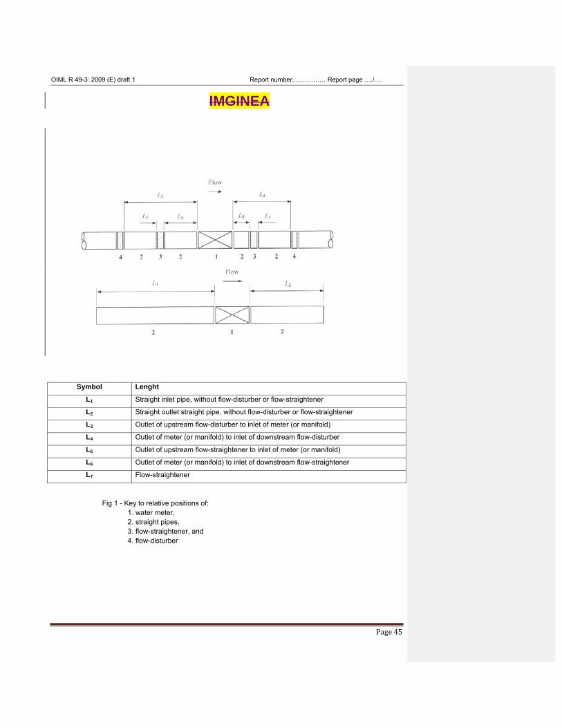
OIML R 49-3: 2009 (E) draft 1 Report number:…………… Report page …./….
Page 45
IMGINEA
Symbol Lenght
L1 Straight inlet pipe, without flow-disturber or flow-straightener
L2 Straight outlet straight pipe, without flow-disturber or flow-straightener
L3 Outlet of upstream flow-disturber to inlet of meter (or manifold)
L4 Outlet of meter (or manifold) to inlet of downstream flow-disturber
L5 Outlet of upstream flow-straightener to inlet of meter (or manifold)
L6 Outlet of meter (or manifold) to inlet of downstream flow-straightener
L7 Flow-straightener
Fig 1 - Key to relative positions of: 1. water meter, 2. straight pipes, 3. flow-straightener, and 4. flow-disturber
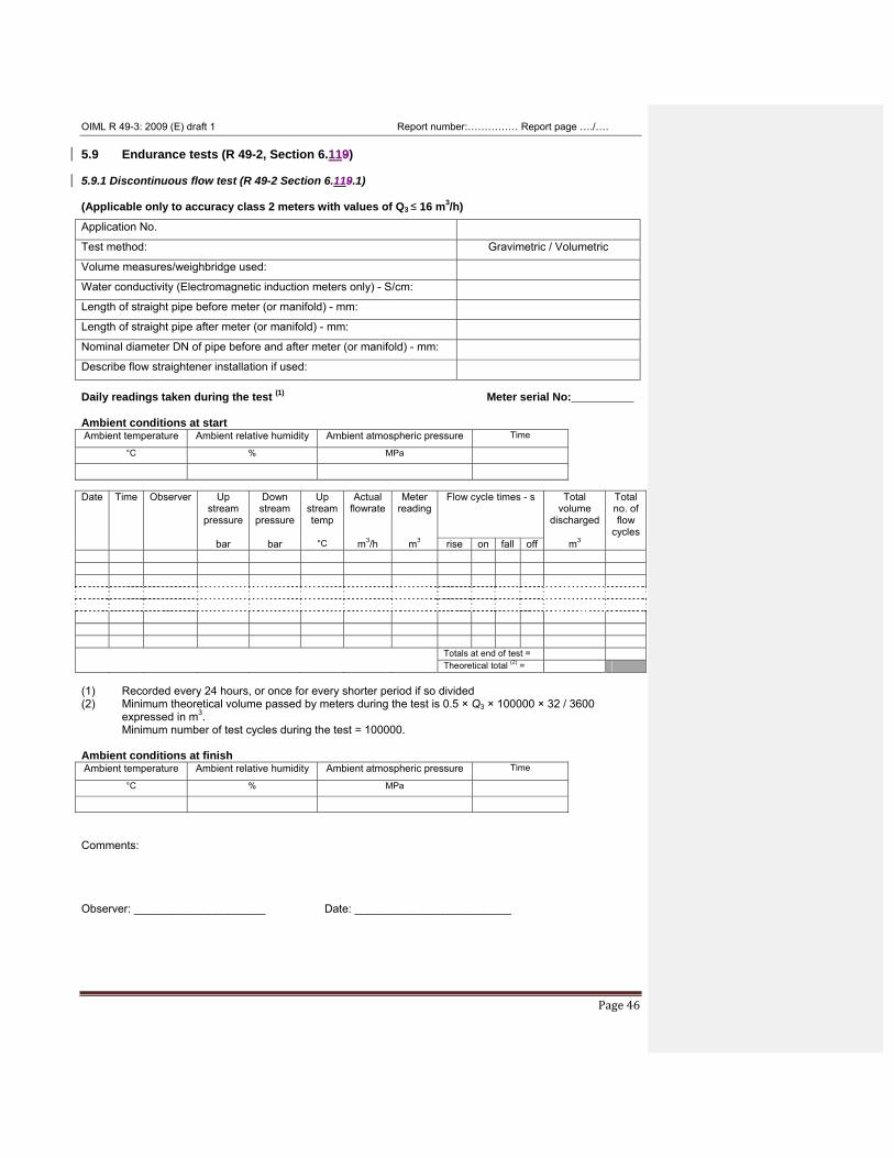
OIML R 49-3: 2009 (E) draft 1 Report number:…………… Report page …./….
Page 46
5.9 Endurance tests (R 49-2, Section 6.119) 5.9.1 Discontinuous flow test (R 49-2 Section 6.119.1) (Applicable only to accuracy class 2 meters with values of Q3 ≤ 16 m3/h)
Application No.
Test method: Gravimetric / Volumetric
Volume measures/weighbridge used:
Water conductivity (Electromagnetic induction meters only) - S/cm:
Length of straight pipe before meter (or manifold) - mm:
Length of straight pipe after meter (or manifold) - mm:
Nominal diameter DN of pipe before and after meter (or manifold) - mm:
Describe flow straightener installation if used:
Daily readings taken during the test (1)
Meter serial No:__________ Ambient conditions at start Ambient temperature Ambient relative humidity Ambient atmospheric pressure Time
°C % MPa
Date Time Observer Up
stream pressure
Down stream
pressure
Up stream temp
Actual flowrate
Meter reading
Flow cycle times - s Total volume
discharged
Total no. of flow
cycles bar bar °C m3/h m3 rise on fall off m3
Totals at end of test = Theoretical total (2) = (1) Recorded every 24 hours, or once for every shorter period if so divided (2) Minimum theoretical volume passed by meters during the test is 0.5 × Q3 × 100000 × 32 / 3600
expressed in m3. Minimum number of test cycles during the test = 100000.
Ambient conditions at finish Ambient temperature Ambient relative humidity Ambient atmospheric pressure Time
°C % MPa
Comments: Observer: _____________________ Date: _________________________
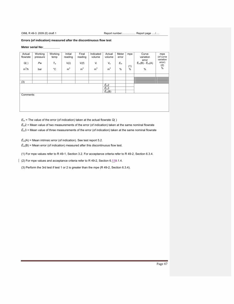
OIML R 49-3: 2009 (E) draft 1 Report number:…………… Report page …./….
Page 47
Errors (of indication) measured after the discontinuous flow test Meter serial No:__________ Actual
flowrate
Q( )
m3/h
Working pressure
Pw
bar
Working temp
Tw
°C
Initial reading
Vi(i)
m3
Final reading
Vi(f)
m3
Indicated volume
VI
m3
Actual volume
Va
m3
Meter error
Em
%
mpe
(1) %
Curve variation
error Ēm(B) - Ēm(A)
%
mpe (of curve variation
error) (2) %
(3) Ēm2 Ēm3 Ēm(B) Comments: Em = The value of the error (of indication) taken at the actual flowrate Q( )
Ēm2 = Mean value of two measurements of the error (of indication) taken at the same nominal flowrate
Ēm3 = Mean value of three measurements of the error (of indication) taken at the same nominal flowrate
Ēm(A) = Mean intrinsic error (of indication). See test report 5.2.
Ēm(B) = Mean error (of indication) measured after this discontinuous flow test.
(1) For mpe values refer to R 49-1, Section 3.2. For acceptance criteria refer to R 49-2, Section 6.3.4. (2) For mpe values and acceptance criteria refer to R 49-2, Section 6.119.1.4. (3) Perform the 3rd test if test 1 or 2 is greater than the mpe (R 49-2, Section 6.3.4).
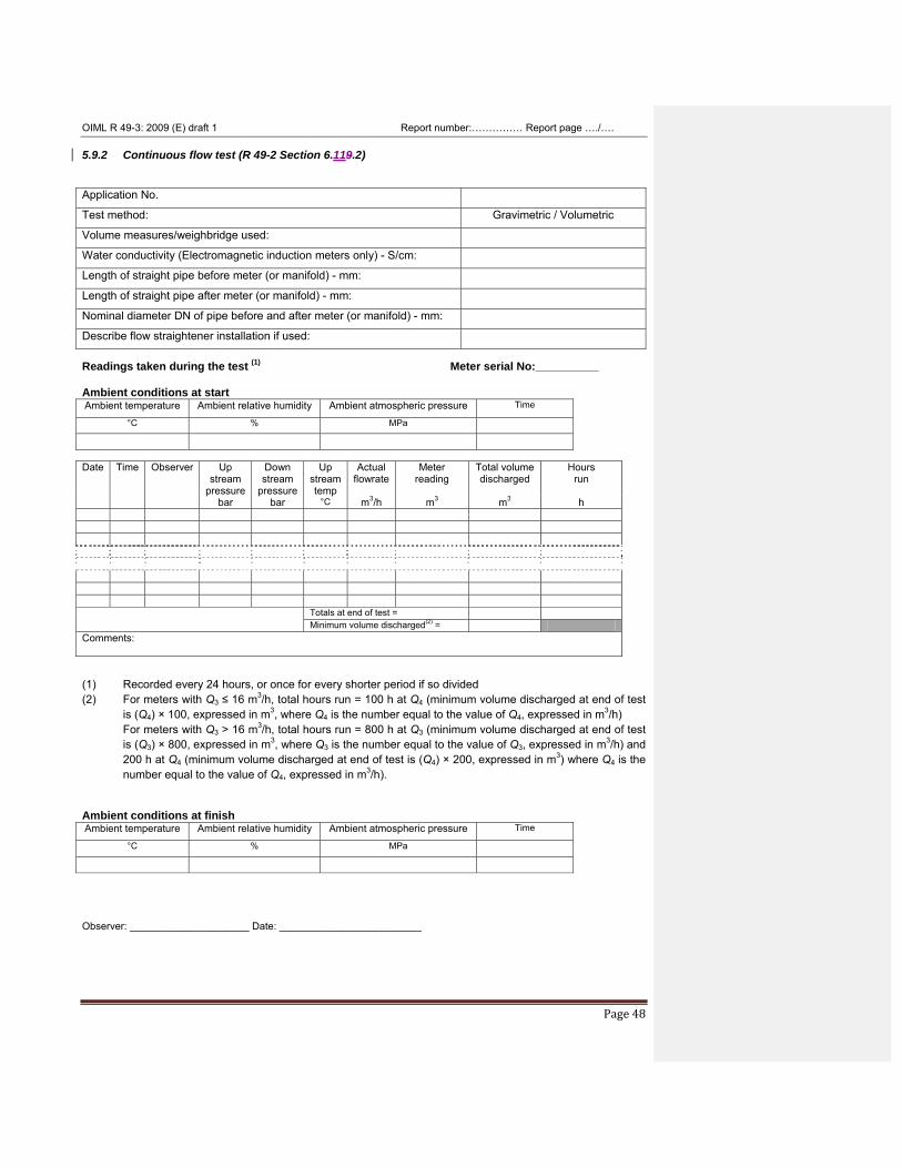
OIML R 49-3: 2009 (E) draft 1 Report number:…………… Report page …./….
Page 48
5.9.2 Continuous flow test (R 49-2 Section 6.119.2) Application No.
Test method: Gravimetric / Volumetric
Volume measures/weighbridge used:
Water conductivity (Electromagnetic induction meters only) - S/cm:
Length of straight pipe before meter (or manifold) - mm:
Length of straight pipe after meter (or manifold) - mm:
Nominal diameter DN of pipe before and after meter (or manifold) - mm:
Describe flow straightener installation if used:
Readings taken during the test (1)
Meter serial No:__________ Ambient conditions at start Ambient temperature Ambient relative humidity Ambient atmospheric pressure Time
°C % MPa
Date Time Observer Up
stream pressure
Down stream
pressure
Up stream temp
Actual flowrate
Meter reading
Total volume discharged
Hours run
bar bar °C m3/h m3 m3 h
Totals at end of test = Minimum volume discharged(2) = Comments:
(1) Recorded every 24 hours, or once for every shorter period if so divided (2) For meters with Q3 ≤ 16 m3/h, total hours run = 100 h at Q4 (minimum volume discharged at end of test
is (Q4) × 100, expressed in m3, where Q4 is the number equal to the value of Q4, expressed in m3/h) For meters with Q3 > 16 m3/h, total hours run = 800 h at Q3 (minimum volume discharged at end of test is (Q3) × 800, expressed in m3, where Q3 is the number equal to the value of Q3, expressed in m3/h) and 200 h at Q4 (minimum volume discharged at end of test is (Q4) × 200, expressed in m3) where Q4 is the number equal to the value of Q4, expressed in m3/h).
Ambient conditions at finish Ambient temperature Ambient relative humidity Ambient atmospheric pressure Time
°C % MPa
Observer: _____________________ Date: _________________________
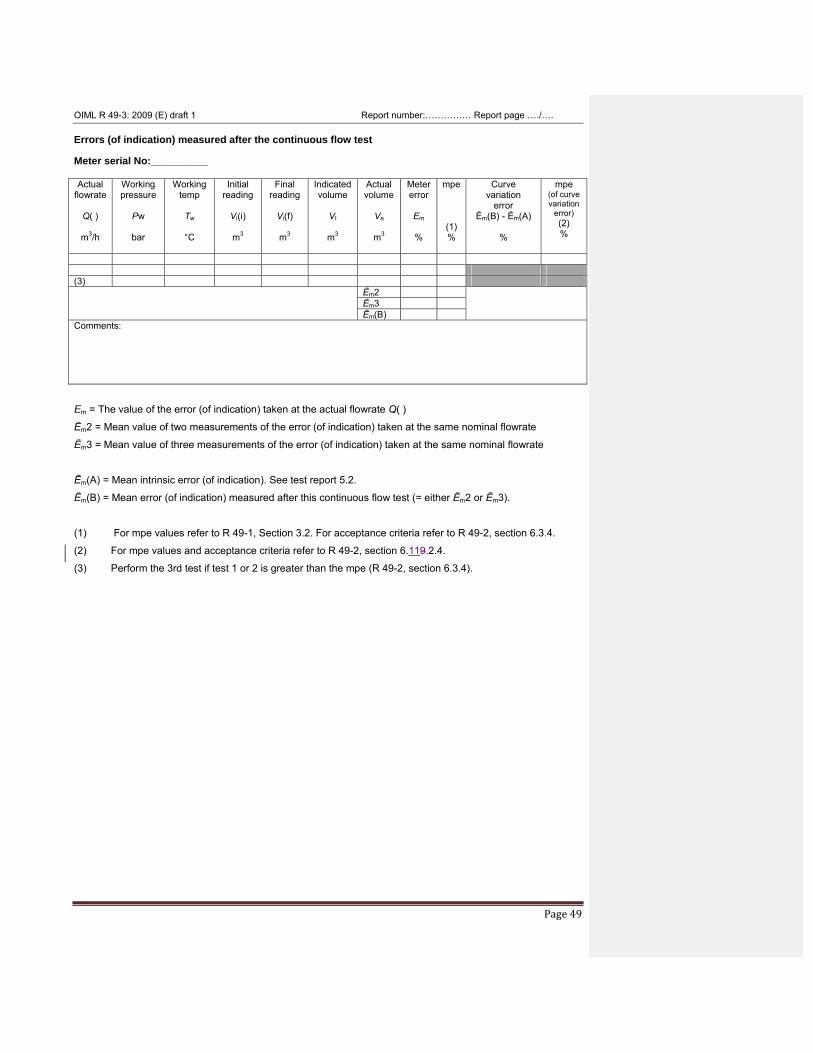
OIML R 49-3: 2009 (E) draft 1 Report number:…………… Report page …./….
Page 49
Errors (of indication) measured after the continuous flow test Meter serial No:__________ Actual
flowrate
Q( )
m3/h
Working pressure
Pw
bar
Working temp
Tw
°C
Initial reading
Vi(i)
m3
Final reading
Vi(f)
m3
Indicated volume
VI
m3
Actual volume
Va
m3
Meter error
Em
%
mpe
(1) %
Curve variation
error Ēm(B) - Ēm(A)
%
mpe (of curve variation
error) (2) %
(3) Ēm2 Ēm3 Ēm(B) Comments: Em = The value of the error (of indication) taken at the actual flowrate Q( )
Ēm2 = Mean value of two measurements of the error (of indication) taken at the same nominal flowrate
Ēm3 = Mean value of three measurements of the error (of indication) taken at the same nominal flowrate
Ēm(A) = Mean intrinsic error (of indication). See test report 5.2.
Ēm(B) = Mean error (of indication) measured after this continuous flow test (= either Ēm2 or Ēm3).
(1) For mpe values refer to R 49-1, Section 3.2. For acceptance criteria refer to R 49-2, section 6.3.4.
(2) For mpe values and acceptance criteria refer to R 49-2, section 6.119.2.4.
(3) Perform the 3rd test if test 1 or 2 is greater than the mpe (R 49-2, section 6.3.4).
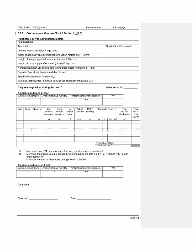
OIML R 49-3: 2009 (E) draft 1 Report number:…………… Report page …./….
Page 50
5.9.3 Discontinuous flow test (R 49-2 Section 6.119.3) (Applicable only to combination meters) Application No.
Test method: Gravimetric / Volumetric
Volume measures/weighbridge used:
Water conductivity (Electromagnetic induction meters only) - S/cm:
Length of straight pipe before meter (or manifold) - mm:
Length of straight pipe after meter (or manifold) - mm:
Nominal diameter DN of pipe before and after meter (or manifold) - mm:
Describe flow straightener installation if used:
Specified changeover flowrate Qx2
Selected test flowrate (minimum is twice the changeover flowrate Qx2)
Daily readings taken during the test (1)
Meter serial No:__________ Ambient conditions at start Ambient temperature Ambient relative humidity Ambient atmospheric pressure Time
°C % MPa
Date Time Observer Up
stream pressure
Down stream
pressure
Up stream temp
Actual flowrate
Meter reading
Flow cycle times - s Total volume
discharged
Total no. of flow
cycles bar bar °C m3/h m3 rise on fall off m3
Totals at end of test = Theoretical total (2) = (1) Recorded every 24 hours, or once for every shorter period if so divided (2) Minimum theoretical volume passed by meters during the test is 0.5 × Q1 × 50000 × 32 / 3600
expressed in m3. Minimum number of test cycles during the test = 50000.
Ambient conditions at finish Ambient temperature Ambient relative humidity Ambient atmospheric pressure Time
°C % MPa
Comments: Observer: _____________________ Date: _________________________
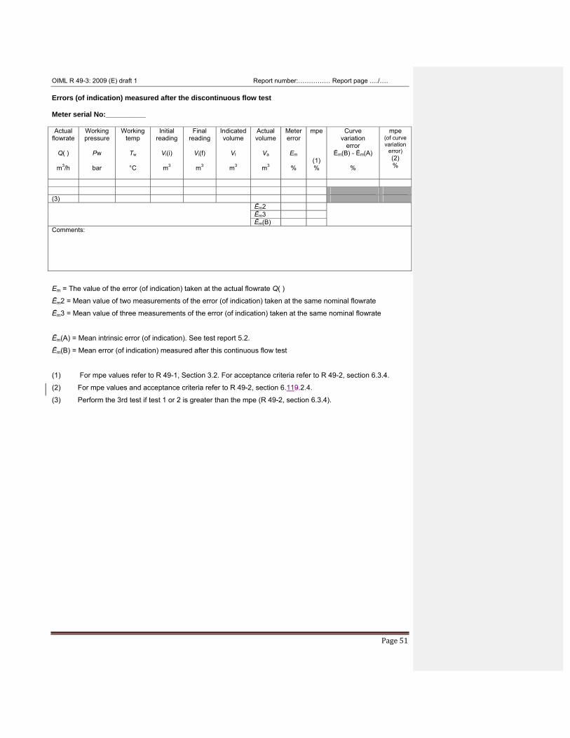
OIML R 49-3: 2009 (E) draft 1 Report number:…………… Report page …./….
Page 51
Errors (of indication) measured after the discontinuous flow test Meter serial No:__________ Actual
flowrate
Q( )
m3/h
Working pressure
Pw
bar
Working temp
Tw
°C
Initial reading
Vi(i)
m3
Final reading
Vi(f)
m3
Indicated volume
VI
m3
Actual volume
Va
m3
Meter error
Em
%
mpe
(1) %
Curve variation
error Ēm(B) - Ēm(A)
%
mpe (of curve variation
error) (2) %
(3) Ēm2 Ēm3 Ēm(B) Comments: Em = The value of the error (of indication) taken at the actual flowrate Q( )
Ēm2 = Mean value of two measurements of the error (of indication) taken at the same nominal flowrate
Ēm3 = Mean value of three measurements of the error (of indication) taken at the same nominal flowrate
Ēm(A) = Mean intrinsic error (of indication). See test report 5.2.
Ēm(B) = Mean error (of indication) measured after this continuous flow test
(1) For mpe values refer to R 49-1, Section 3.2. For acceptance criteria refer to R 49-2, section 6.3.4.
(2) For mpe values and acceptance criteria refer to R 49-2, section 6.119.2.4.
(3) Perform the 3rd test if test 1 or 2 is greater than the mpe (R 49-2, section 6.3.4).
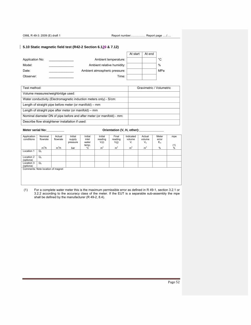
OIML R 49-3: 2009 (E) draft 1 Report number:…………… Report page …./….
Page 52
5.10 Static magnetic field test (R42-2 Section 6.120 & 7.12) At start At end
Application No: ______________ Ambient temperature: °C
Model: ______________ Ambient relative humidity: %
Date: ______________ Ambient atmospheric pressure: MPa
Observer: ______________ Time: Test method: Gravimetric / Volumetric
Volume measures/weighbridge used:
Water conductivity (Electromagnetic induction meters only) - S/cm:
Length of straight pipe before meter (or manifold) – mm
Length of straight pipe after meter (or manifold) – mm
Nominal diameter DN of pipe before and after meter (or manifold) - mm:
Describe flow straightener installation if used:
Meter serial No:__________ Orientation (V, H, other):______________ Application conditions
Nominal flowrate
m3/h
Actual flowrate
m3/h
Initial supply
pressure
bar
Initial inlet
water temp.
°C
Initial reading
Vi(i)
m3
Final reading
Vi(j)
m3
Indicated volume
Vi
m3
Actual volume
Va
m3
Meter error Em
%
mpe
(1) %
Location 1
Q3
Location 2 (optiona)
Q3
Location 3 (optiona)
Q3
Comments: Note location of magnet (1) For a complete water meter this is the maximum permissible error as defined in R 49-1, section 3.2.1 or
3.2.2 according to the accuracy class of the meter. If the EUT is a separable sub-assembly the mpe shall be defined by the manufacturer (R 49-2, 8.4).
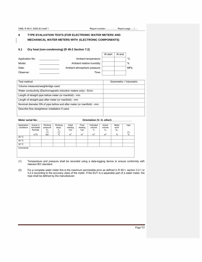
OIML R 49-3: 2009 (E) draft 1 Report number:…………… Report page …./….
Page 53
6 TYPE EVALUATION TESTS (FOR ELECTRONIC WATER METERS AND MECHANICAL WATER METERS WITH ELECTRONIC COMPONENTS)
6.1 Dry heat (non-condensing) (R 49-2 Section 7.2) At start At end
Application No: ______________ Ambient temperature: °C
Model: ______________ Ambient relative humidity: %
Date: ______________ Ambient atmospheric pressure: MPa
Observer: ______________ Time: Test method: Gravimetric / Volumetric
Volume measures/weighbridge used:
Water conductivity (Electromagnetic induction meters only) - S/cm:
Length of straight pipe before meter (or manifold) - mm
Length of straight pipe after meter (or manifold) - mm
Nominal diameter DN of pipe before and after meter (or manifold) - mm:
Describe flow straightener installation if used:
Meter serial No:__________ Orientation (V, H, other):______________ Application conditions
Actual or simulated flowrate
m3/h
Working pressure
Pw (1) bar
Working temp.
Tw (1) °C
Initial reading
Vi(i)
m3
Final reading
Vi(j)
m3
Indicated volume
Vi
m3
Actual volume
Va
m3
Meter error Em
%
mpe
(1) %
20 °C
55 °C
20 °C
Comments:
(1) Temperature and pressure shall be recorded using a data-logging device to ensure conformity with
relevant IEC standard. (2) For a complete water meter this is the maximum permissible error as defined in R 49-1, section 3.2.1 or
3.2.2 according to the accuracy class of the meter. If the EUT is a separable part of a water meter, the mpe shall be defined by the manufacturer.
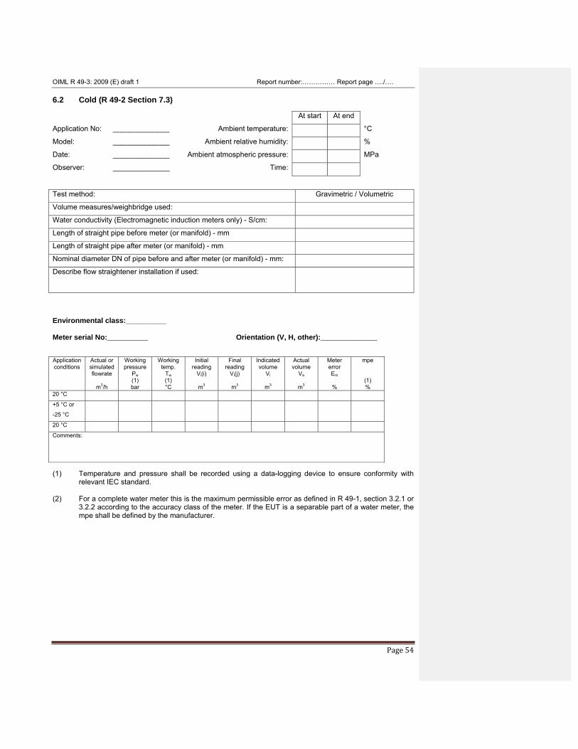
OIML R 49-3: 2009 (E) draft 1 Report number:…………… Report page …./….
Page 54
6.2 Cold (R 49-2 Section 7.3) At start At end
Application No: ______________ Ambient temperature: °C
Model: ______________ Ambient relative humidity: %
Date: ______________ Ambient atmospheric pressure: MPa
Observer: ______________ Time: Test method: Gravimetric / Volumetric
Volume measures/weighbridge used:
Water conductivity (Electromagnetic induction meters only) - S/cm:
Length of straight pipe before meter (or manifold) - mm
Length of straight pipe after meter (or manifold) - mm
Nominal diameter DN of pipe before and after meter (or manifold) - mm:
Describe flow straightener installation if used:
Environmental class:__________
Meter serial No:__________ Orientation (V, H, other):______________
Application conditions
Actual or simulated flowrate
m3/h
Working pressure
Pw (1) bar
Working temp.
Tw (1) °C
Initial reading
Vi(i)
m3
Final reading
Vi(j)
m3
Indicated volume
Vi
m3
Actual volume
Va
m3
Meter error Em
%
mpe
(1) %
20 °C
+5 °C or
-25 °C
20 °C
Comments:
(1) Temperature and pressure shall be recorded using a data-logging device to ensure conformity with
relevant IEC standard. (2) For a complete water meter this is the maximum permissible error as defined in R 49-1, section 3.2.1 or
3.2.2 according to the accuracy class of the meter. If the EUT is a separable part of a water meter, the mpe shall be defined by the manufacturer.
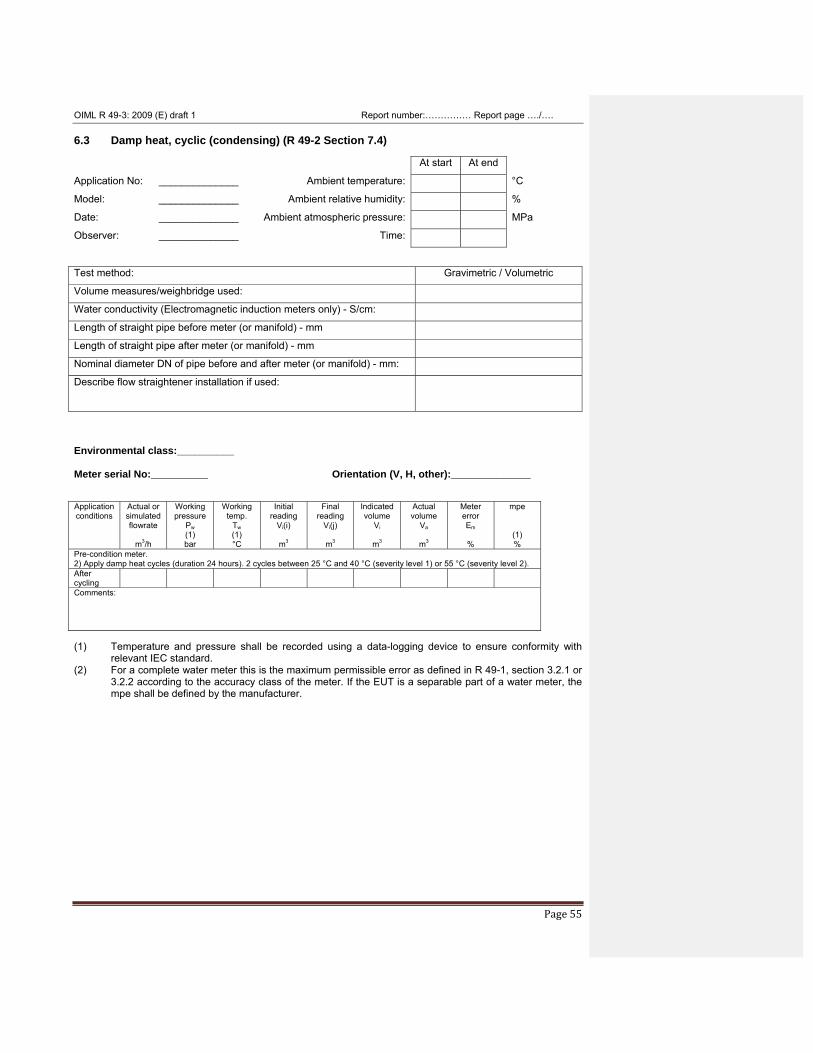
OIML R 49-3: 2009 (E) draft 1 Report number:…………… Report page …./….
Page 55
6.3 Damp heat, cyclic (condensing) (R 49-2 Section 7.4) At start At end
Application No: ______________ Ambient temperature: °C
Model: ______________ Ambient relative humidity: %
Date: ______________ Ambient atmospheric pressure: MPa
Observer: ______________ Time: Test method: Gravimetric / Volumetric
Volume measures/weighbridge used:
Water conductivity (Electromagnetic induction meters only) - S/cm:
Length of straight pipe before meter (or manifold) - mm
Length of straight pipe after meter (or manifold) - mm
Nominal diameter DN of pipe before and after meter (or manifold) - mm:
Describe flow straightener installation if used:
Environmental class:__________
Meter serial No:__________ Orientation (V, H, other):______________
Application conditions
Actual or simulated flowrate
m3/h
Working pressure
Pw (1) bar
Working temp.
Tw (1) °C
Initial reading
Vi(i)
m3
Final reading
Vi(j)
m3
Indicated volume
Vi
m3
Actual volume
Va
m3
Meter error Em
%
mpe
(1) %
Pre-condition meter. 2) Apply damp heat cycles (duration 24 hours). 2 cycles between 25 °C and 40 °C (severity level 1) or 55 °C (severity level 2). After cycling
Comments:
(1) Temperature and pressure shall be recorded using a data-logging device to ensure conformity with
relevant IEC standard. (2) For a complete water meter this is the maximum permissible error as defined in R 49-1, section 3.2.1 or
3.2.2 according to the accuracy class of the meter. If the EUT is a separable part of a water meter, the mpe shall be defined by the manufacturer.
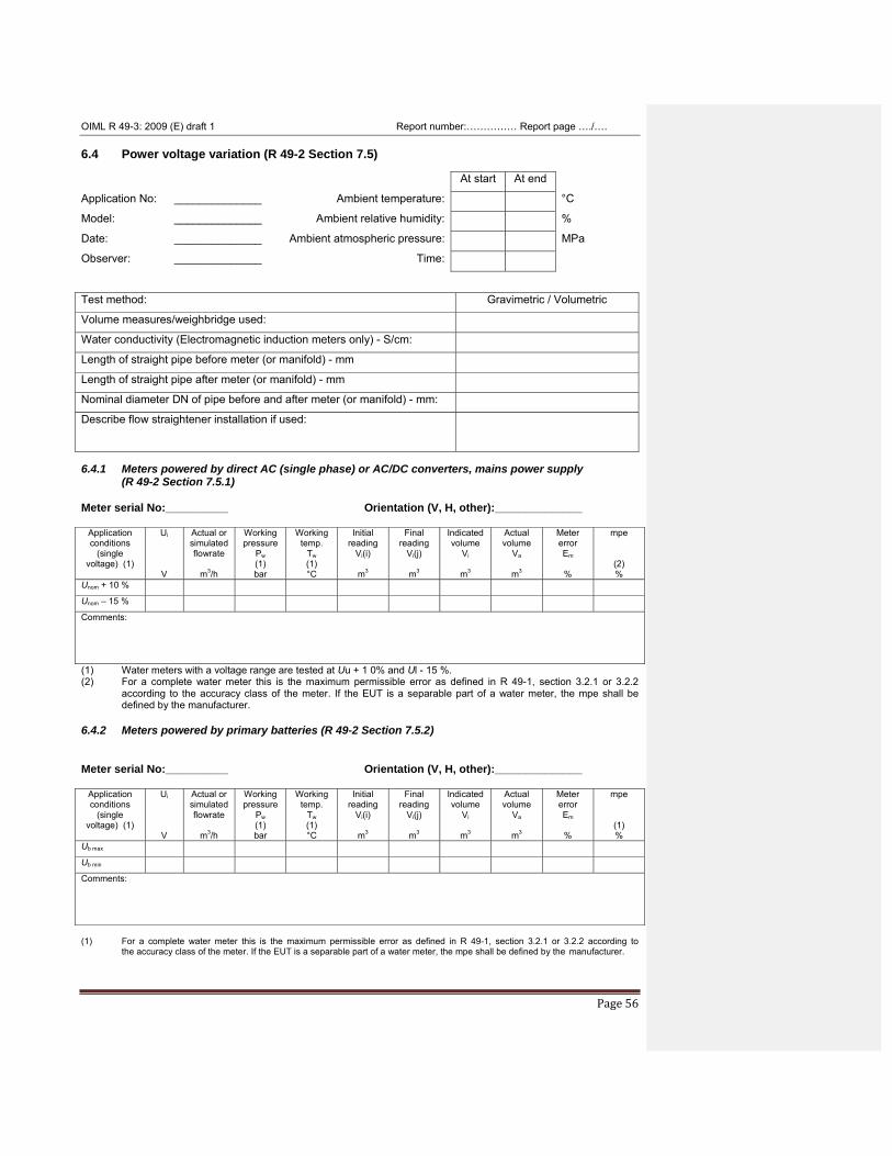
OIML R 49-3: 2009 (E) draft 1 Report number:…………… Report page …./….
Page 56
6.4 Power voltage variation (R 49-2 Section 7.5) At start At end
Application No: ______________ Ambient temperature: °C
Model: ______________ Ambient relative humidity: %
Date: ______________ Ambient atmospheric pressure: MPa
Observer: ______________ Time: Test method: Gravimetric / Volumetric
Volume measures/weighbridge used:
Water conductivity (Electromagnetic induction meters only) - S/cm:
Length of straight pipe before meter (or manifold) - mm
Length of straight pipe after meter (or manifold) - mm
Nominal diameter DN of pipe before and after meter (or manifold) - mm:
Describe flow straightener installation if used:
6.4.1 Meters powered by direct AC (single phase) or AC/DC converters, mains power supply
(R 49-2 Section 7.5.1)
Meter serial No:__________ Orientation (V, H, other):______________
Application conditions
(single voltage) (1)
Ui
V
Actual or simulated flowrate
m3/h
Working pressure
Pw (1) bar
Working temp.
Tw (1) °C
Initial reading
Vi(i)
m3
Final reading
Vi(j)
m3
Indicated volume
Vi
m3
Actual volume
Va
m3
Meter error Em
%
mpe
(2) %
Unom + 10 %
Unom – 15 %
Comments:
(1) Water meters with a voltage range are tested at Uu + 1 0% and Ul - 15 %. (2) For a complete water meter this is the maximum permissible error as defined in R 49-1, section 3.2.1 or 3.2.2
according to the accuracy class of the meter. If the EUT is a separable part of a water meter, the mpe shall be defined by the manufacturer.
6.4.2 Meters powered by primary batteries (R 49-2 Section 7.5.2)
Meter serial No:__________ Orientation (V, H, other):______________
Application conditions
(single voltage) (1)
Ui
V
Actual or simulated flowrate
m3/h
Working pressure
Pw (1) bar
Working temp.
Tw (1) °C
Initial reading
Vi(i)
m3
Final reading
Vi(j)
m3
Indicated volume
Vi
m3
Actual volume
Va
m3
Meter error Em
%
mpe
(1) %
Ub max
Ub min
Comments:
(1) For a complete water meter this is the maximum permissible error as defined in R 49-1, section 3.2.1 or 3.2.2 according to the accuracy class of the meter. If the EUT is a separable part of a water meter, the mpe shall be defined by the manufacturer.
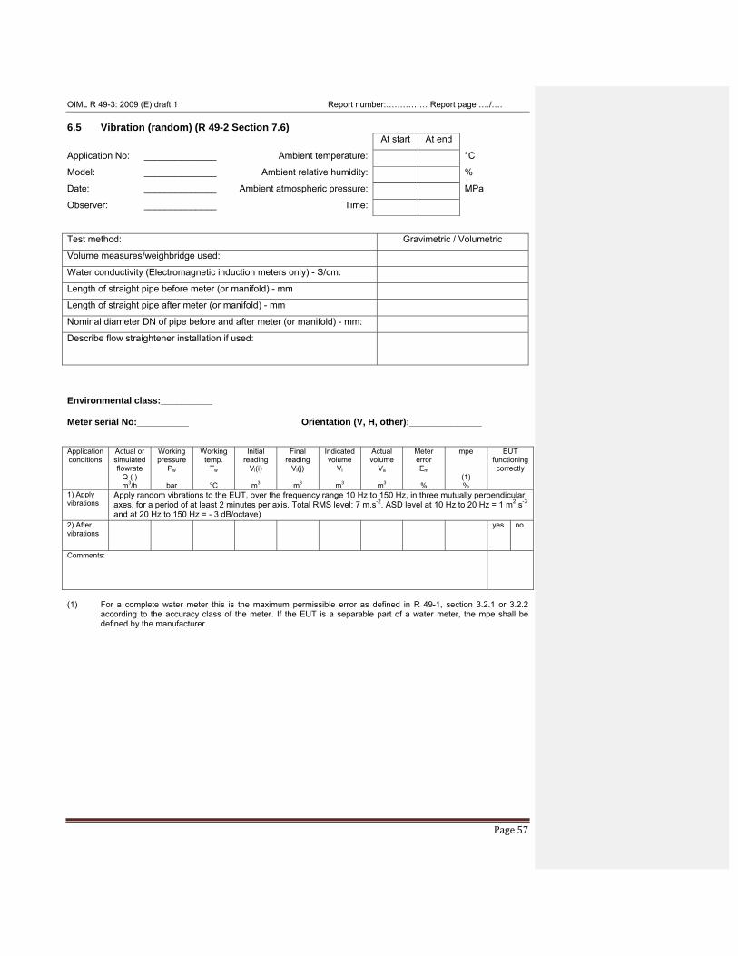
OIML R 49-3: 2009 (E) draft 1 Report number:…………… Report page …./….
Page 57
6.5 Vibration (random) (R 49-2 Section 7.6) At start At end
Application No: ______________ Ambient temperature: °C
Model: ______________ Ambient relative humidity: %
Date: ______________ Ambient atmospheric pressure: MPa
Observer: ______________ Time: Test method: Gravimetric / Volumetric
Volume measures/weighbridge used:
Water conductivity (Electromagnetic induction meters only) - S/cm:
Length of straight pipe before meter (or manifold) - mm
Length of straight pipe after meter (or manifold) - mm
Nominal diameter DN of pipe before and after meter (or manifold) - mm:
Describe flow straightener installation if used:
Environmental class:__________
Meter serial No:__________ Orientation (V, H, other):______________
Application conditions
Actual or simulated flowrate
Q ( ) m3/h
Working pressure
Pw
bar
Working temp.
Tw
°C
Initial reading
Vi(i)
m3
Final reading
Vi(j)
m3
Indicated volume
Vi
m3
Actual volume
Va
m3
Meter error Em
%
mpe
(1) %
EUT functioning correctly
1) Apply vibrations
Apply random vibrations to the EUT, over the frequency range 10 Hz to 150 Hz, in three mutually perpendicular axes, for a period of at least 2 minutes per axis. Total RMS level: 7 m.s-2. ASD level at 10 Hz to 20 Hz = 1 m2.s-3 and at 20 Hz to 150 Hz = - 3 dB/octave)
2) After vibrations
yes no
Comments:
(1) For a complete water meter this is the maximum permissible error as defined in R 49-1, section 3.2.1 or 3.2.2
according to the accuracy class of the meter. If the EUT is a separable part of a water meter, the mpe shall be defined by the manufacturer.
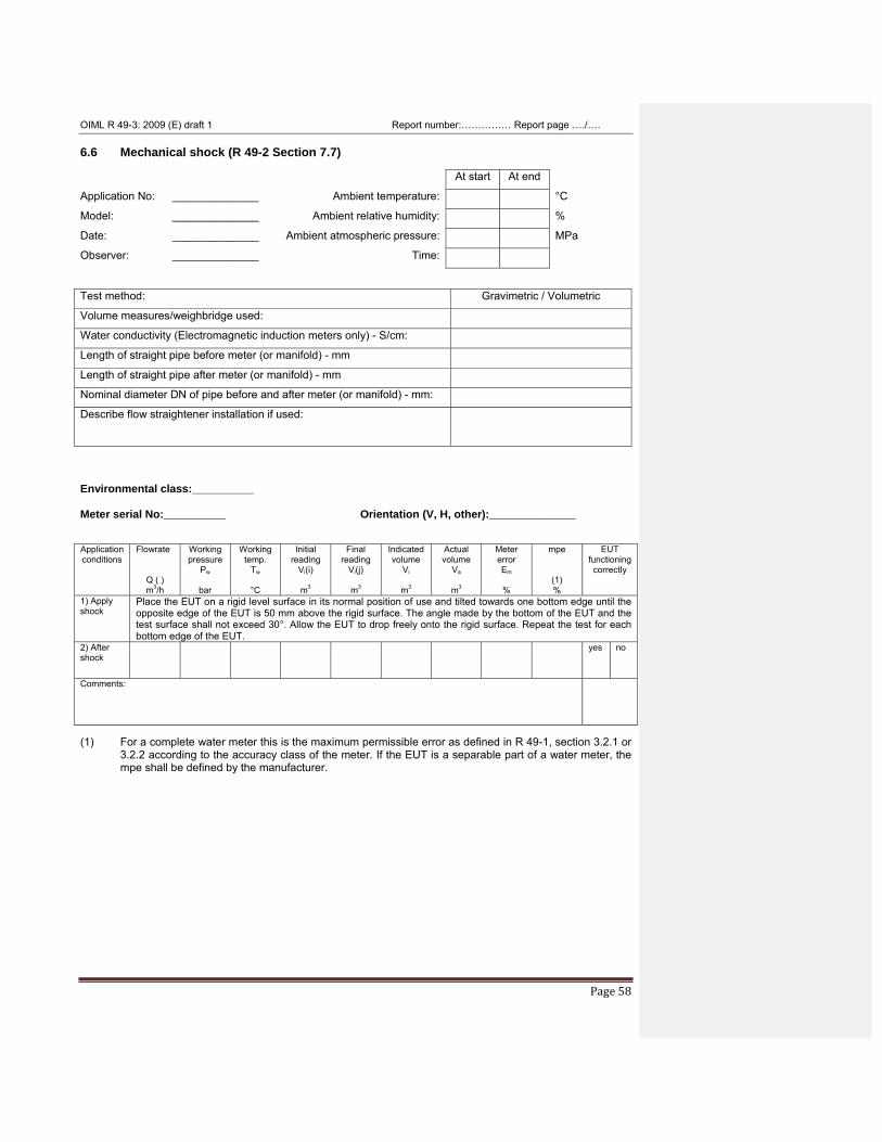
OIML R 49-3: 2009 (E) draft 1 Report number:…………… Report page …./….
Page 58
6.6 Mechanical shock (R 49-2 Section 7.7) At start At end
Application No: ______________ Ambient temperature: °C
Model: ______________ Ambient relative humidity: %
Date: ______________ Ambient atmospheric pressure: MPa
Observer: ______________ Time: Test method: Gravimetric / Volumetric
Volume measures/weighbridge used:
Water conductivity (Electromagnetic induction meters only) - S/cm:
Length of straight pipe before meter (or manifold) - mm
Length of straight pipe after meter (or manifold) - mm
Nominal diameter DN of pipe before and after meter (or manifold) - mm:
Describe flow straightener installation if used:
Environmental class:__________
Meter serial No:__________ Orientation (V, H, other):______________
Application conditions
Flowrate
Q ( ) m3/h
Working pressure
Pw
bar
Working temp.
Tw
°C
Initial reading
Vi(i)
m3
Final reading
Vi(j)
m3
Indicated volume
Vi
m3
Actual volume
Va
m3
Meter error Em
%
mpe
(1) %
EUT functioning correctly
1) Apply shock
Place the EUT on a rigid level surface in its normal position of use and tilted towards one bottom edge until the opposite edge of the EUT is 50 mm above the rigid surface. The angle made by the bottom of the EUT and the test surface shall not exceed 30°. Allow the EUT to drop freely onto the rigid surface. Repeat the test for each bottom edge of the EUT.
2) After shock
yes no
Comments:
(1) For a complete water meter this is the maximum permissible error as defined in R 49-1, section 3.2.1 or
3.2.2 according to the accuracy class of the meter. If the EUT is a separable part of a water meter, the mpe shall be defined by the manufacturer.
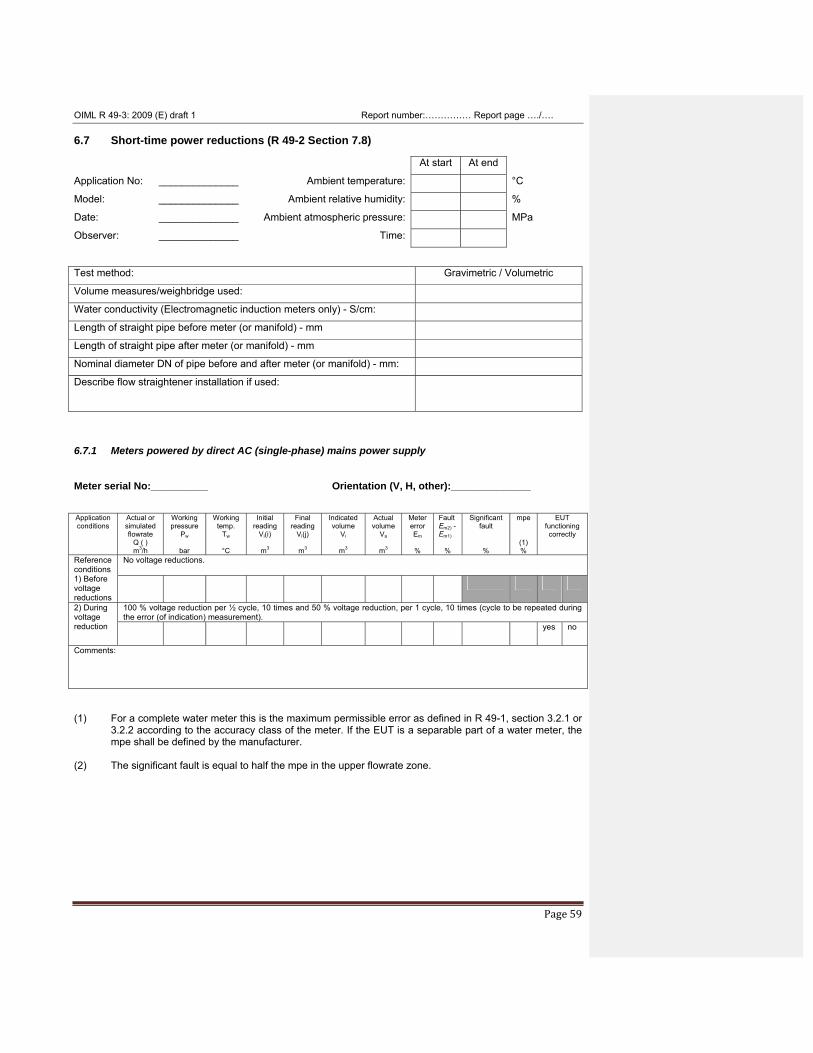
OIML R 49-3: 2009 (E) draft 1 Report number:…………… Report page …./….
Page 59
6.7 Short-time power reductions (R 49-2 Section 7.8) At start At end
Application No: ______________ Ambient temperature: °C
Model: ______________ Ambient relative humidity: %
Date: ______________ Ambient atmospheric pressure: MPa
Observer: ______________ Time: Test method: Gravimetric / Volumetric
Volume measures/weighbridge used:
Water conductivity (Electromagnetic induction meters only) - S/cm:
Length of straight pipe before meter (or manifold) - mm
Length of straight pipe after meter (or manifold) - mm
Nominal diameter DN of pipe before and after meter (or manifold) - mm:
Describe flow straightener installation if used:
6.7.1 Meters powered by direct AC (single-phase) mains power supply
Meter serial No:__________ Orientation (V, H, other):______________
Application conditions
Actual or simulated flowrate
Q ( ) m3/h
Working pressure
Pw
bar
Working temp.
Tw
°C
Initial reading
Vi(i)
m3
Final reading
Vi(j)
m3
Indicated volume
Vi
m3
Actual volume
Va
m3
Meter error Em
%
Fault Em2) -Em1)
%
Significant fault
%
mpe
(1) %
EUT functioning correctly
Reference conditions 1) Before voltage reductions
No voltage reductions.
2) During voltage reduction
100 % voltage reduction per ½ cycle, 10 times and 50 % voltage reduction, per 1 cycle, 10 times (cycle to be repeated during the error (of indication) measurement). yes no
Comments:
(1) For a complete water meter this is the maximum permissible error as defined in R 49-1, section 3.2.1 or
3.2.2 according to the accuracy class of the meter. If the EUT is a separable part of a water meter, the mpe shall be defined by the manufacturer.
(2) The significant fault is equal to half the mpe in the upper flowrate zone.
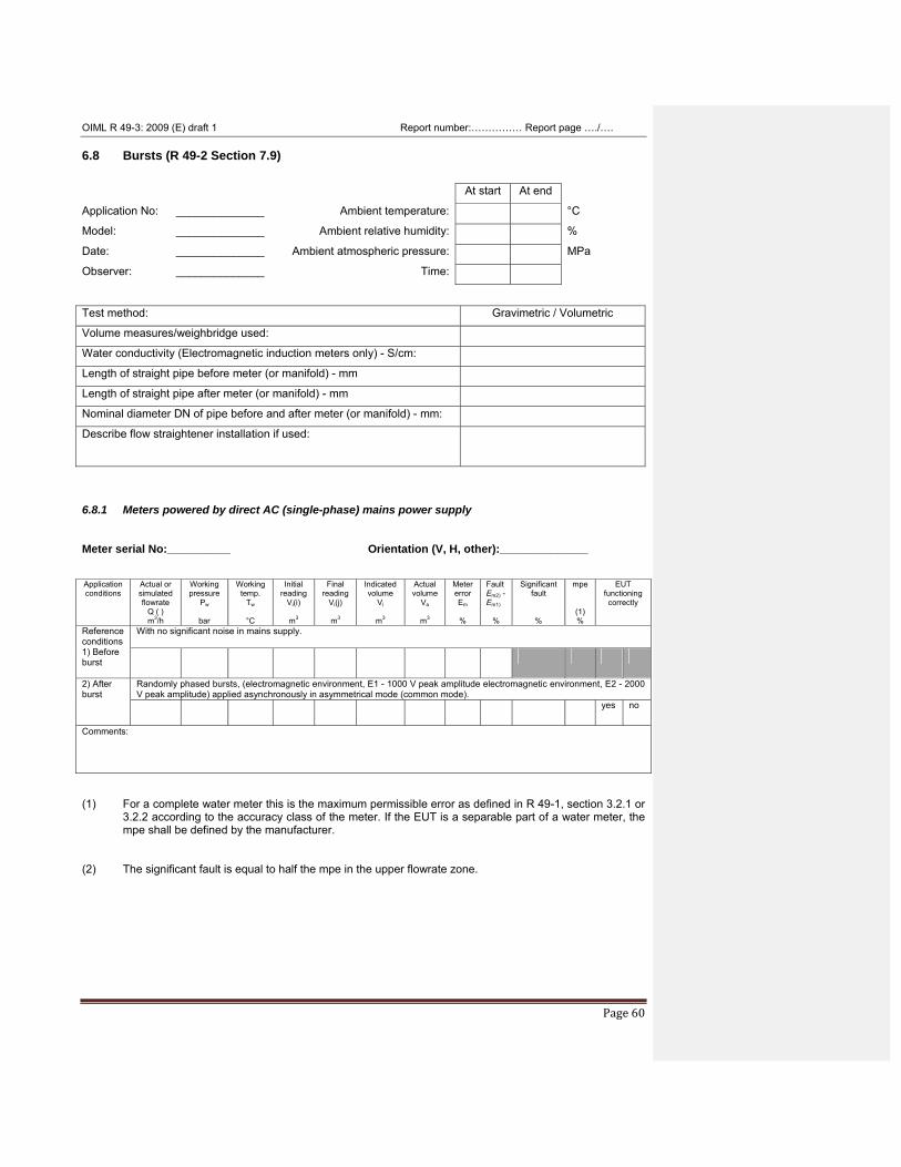
OIML R 49-3: 2009 (E) draft 1 Report number:…………… Report page …./….
Page 60
6.8 Bursts (R 49-2 Section 7.9) At start At end
Application No: ______________ Ambient temperature: °C
Model: ______________ Ambient relative humidity: %
Date: ______________ Ambient atmospheric pressure: MPa
Observer: ______________ Time: Test method: Gravimetric / Volumetric
Volume measures/weighbridge used:
Water conductivity (Electromagnetic induction meters only) - S/cm:
Length of straight pipe before meter (or manifold) - mm
Length of straight pipe after meter (or manifold) - mm
Nominal diameter DN of pipe before and after meter (or manifold) - mm:
Describe flow straightener installation if used:
6.8.1 Meters powered by direct AC (single-phase) mains power supply
Meter serial No:__________ Orientation (V, H, other):______________
Application conditions
Actual or simulated flowrate
Q ( ) m3/h
Working pressure
Pw
bar
Working temp.
Tw
°C
Initial reading
Vi(i)
m3
Final reading
Vi(j)
m3
Indicated volume
Vi
m3
Actual volume
Va
m3
Meter error Em
%
Fault Em2) -Em1)
%
Significant fault
%
mpe
(1) %
EUT functioning correctly
Reference conditions 1) Before burst
With no significant noise in mains supply.
2) After burst
Randomly phased bursts, (electromagnetic environment, E1 - 1000 V peak amplitude electromagnetic environment, E2 - 2000 V peak amplitude) applied asynchronously in asymmetrical mode (common mode). yes no
Comments:
(1) For a complete water meter this is the maximum permissible error as defined in R 49-1, section 3.2.1 or
3.2.2 according to the accuracy class of the meter. If the EUT is a separable part of a water meter, the mpe shall be defined by the manufacturer.
(2) The significant fault is equal to half the mpe in the upper flowrate zone.
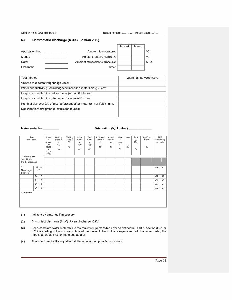
OIML R 49-3: 2009 (E) draft 1 Report number:…………… Report page …./….
Page 61
6.9 Electrostatic discharge (R 49-2 Section 7.10) At start At end
Application No: ______________ Ambient temperature: °C
Model: ______________ Ambient relative humidity: %
Date: ______________ Ambient atmospheric pressure: MPa
Observer: ______________ Time: Test method: Gravimetric / Volumetric
Volume measures/weighbridge used:
Water conductivity (Electromagnetic induction meters only) - S/cm:
Length of straight pipe before meter (or manifold) - mm
Length of straight pipe after meter (or manifold) - mm
Nominal diameter DN of pipe before and after meter (or manifold) - mm:
Describe flow straightener installation if used:
Meter serial No:__________ Orientation (V, H, other):______________
Test
conditions Actual
or simula
ted flowra
te Q ( ) m3/h
Working pressur
e Pw
bar
Working temp.
Tw
°C
Initial readin
g Vi(i)
m3
Final readin
g Vi(j)
m3
Indicated volume
Vi
m3
Actual volume
Va
m3
Meter
error Em
%
mpe
(3) %
Fault Em2) -Em1)
%
Significant fault
%
EUT functioning correctly
1) Reference conditions (nodischarges)
2) Discharge point (1)
Mode (2)
yes no
C A yes no
C A yes no
C A yes no
C A yes no
Comments:
(1) Indicate by drawings if necessary (2) C - contact discharge (6 kV), A - air discharge (8 kV) (3) For a complete water meter this is the maximum permissible error as defined in R 49-1, section 3.2.1 or
3.2.2 according to the accuracy class of the meter. If the EUT is a separable part of a water meter, the mpe shall be defined by the manufacturer.
(4) The significant fault is equal to half the mpe in the upper flowrate zone.
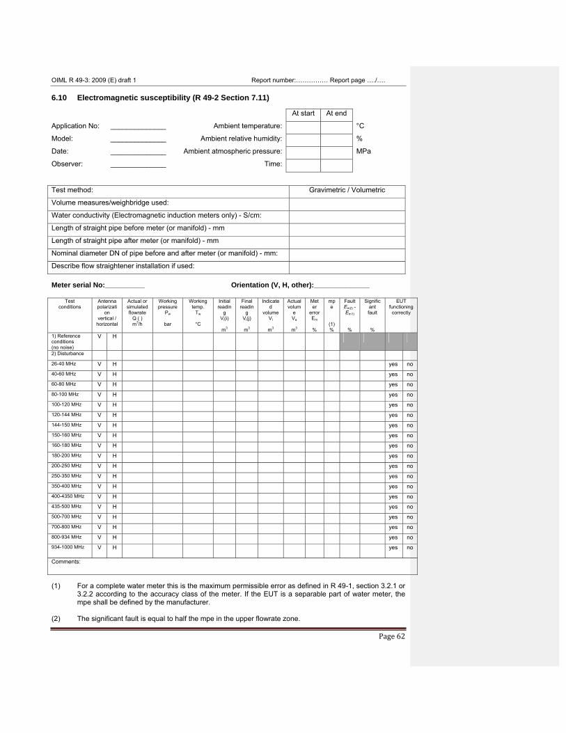
OIML R 49-3: 2009 (E) draft 1 Report number:…………… Report page …./….
Page 62
6.10 Electromagnetic susceptibility (R 49-2 Section 7.11) At start At end
Application No: ______________ Ambient temperature: °C
Model: ______________ Ambient relative humidity: %
Date: ______________ Ambient atmospheric pressure: MPa
Observer: ______________ Time: Test method: Gravimetric / Volumetric
Volume measures/weighbridge used:
Water conductivity (Electromagnetic induction meters only) - S/cm:
Length of straight pipe before meter (or manifold) - mm
Length of straight pipe after meter (or manifold) - mm
Nominal diameter DN of pipe before and after meter (or manifold) - mm:
Describe flow straightener installation if used:
Meter serial No:__________ Orientation (V, H, other):______________
Test conditions
Antenna polarizati
on vertical /
horizontal
Actual or simulated flowrate
Q ( ) m3/h
Working pressure
Pw
bar
Working temp.
Tw
°C
Initial readin
g Vi(i)
m3
Final readin
g Vi(j)
m3
Indicated
volume Vi
m3
Actual volum
e Va
m3
Meter
error Em
%
mpe
(1) %
Fault Em2) -Em1)
%
Significant fault
%
EUT functioning correctly
1) Reference conditions (no noise)
V H
2) Disturbance
26-40 MHz V H yes no
40-60 MHz V H yes no
60-80 MHz V H yes no
80-100 MHz V H yes no
100-120 MHz V H yes no
120-144 MHz V H yes no
144-150 MHz V H yes no
150-160 MHz V H yes no
160-180 MHz V H yes no
180-200 MHz V H yes no
200-250 MHz V H yes no
250-350 MHz V H yes no
350-400 MHz V H yes no
400-4350 MHz V H yes no
435-500 MHz V H yes no
500-700 MHz V H yes no
700-800 MHz V H yes no
800-934 MHz V H yes no
934-1000 MHz V H yes no
Comments:
(1) For a complete water meter this is the maximum permissible error as defined in R 49-1, section 3.2.1 or
3.2.2 according to the accuracy class of the meter. If the EUT is a separable part of water meter, the mpe shall be defined by the manufacturer.
(2) The significant fault is equal to half the mpe in the upper flowrate zone.
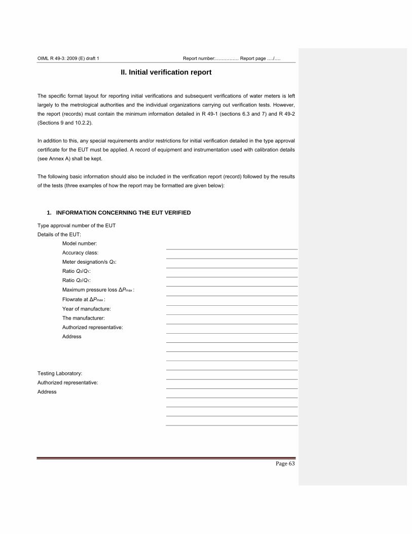
OIML R 49-3: 2009 (E) draft 1 Report number:…………… Report page …./….
Page 63
II. Initial verification report
The specific format layout for reporting initial verifications and subsequent verifications of water meters is left
largely to the metrological authorities and the individual organizations carrying out verification tests. However,
the report (records) must contain the minimum information detailed in R 49-1 (sections 6.3 and 7) and R 49-2
(Sections 9 and 10.2.2).
In addition to this, any special requirements and/or restrictions for initial verification detailed in the type approval
certificate for the EUT must be applied. A record of equipment and instrumentation used with calibration details
(see Annex A) shall be kept.
The following basic information should also be included in the verification report (record) followed by the results
of the tests (three examples of how the report may be formatted are given below):
1. INFORMATION CONCERNING THE EUT VERIFIED
Type approval number of the EUT
Details of the EUT:
Model number:
Accuracy class:
Meter designation/s Q3:
Ratio Q3/Q1:
Ratio Q2/Q1:
Maximum pressure loss ΔPmax :
Flowrate at ΔPmax :
Year of manufacture:
The manufacturer:
Authorized representative:
Address
Testing Laboratory:
Authorized representative:
Address
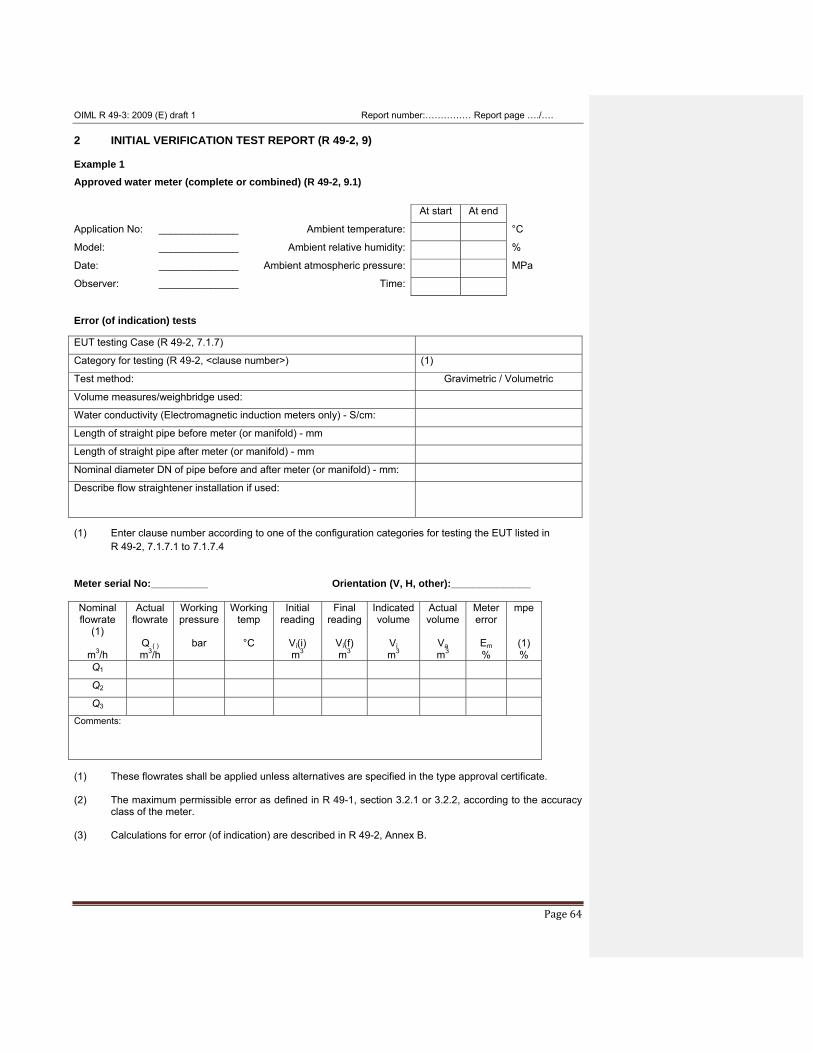
OIML R 49-3: 2009 (E) draft 1 Report number:…………… Report page …./….
Page 64
2 INITIAL VERIFICATION TEST REPORT (R 49-2, 9) Example 1 Approved water meter (complete or combined) (R 49-2, 9.1) At start At end
Application No: ______________ Ambient temperature: °C
Model: ______________ Ambient relative humidity: %
Date: ______________ Ambient atmospheric pressure: MPa
Observer: ______________ Time: Error (of indication) tests EUT testing Case (R 49-2, 7.1.7)
Category for testing (R 49-2, <clause number>) (1)
Test method: Gravimetric / Volumetric
Volume measures/weighbridge used:
Water conductivity (Electromagnetic induction meters only) - S/cm:
Length of straight pipe before meter (or manifold) - mm
Length of straight pipe after meter (or manifold) - mm
Nominal diameter DN of pipe before and after meter (or manifold) - mm:
Describe flow straightener installation if used:
(1) Enter clause number according to one of the configuration categories for testing the EUT listed in
R 49-2, 7.1.7.1 to 7.1.7.4
Meter serial No:__________ Orientation (V, H, other):______________
Nominal flowrate
(1)
m3/h
Actual flowrate
Q ( ) m3/h
Working pressure
bar
Working temp
°C
Initial reading
Vi(i) m3
Final reading
Vi(f) m3
Indicatedvolume
Vi m3
Actual volume
Va m3
Meter error
Em %
mpe
(1) %
Q1
Q2
Q3
Comments:
(1) These flowrates shall be applied unless alternatives are specified in the type approval certificate. (2) The maximum permissible error as defined in R 49-1, section 3.2.1 or 3.2.2, according to the accuracy
class of the meter. (3) Calculations for error (of indication) are described in R 49-2, Annex B.
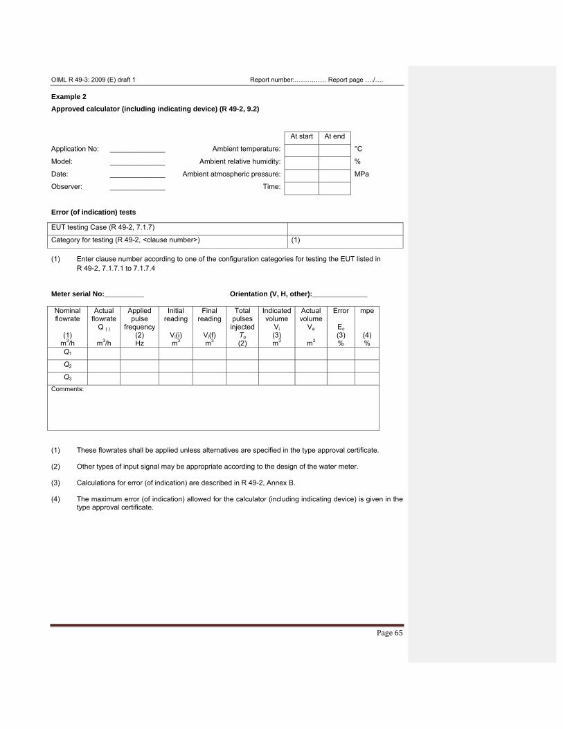
OIML R 49-3: 2009 (E) draft 1 Report number:…………… Report page …./….
Page 65
Example 2 Approved calculator (including indicating device) (R 49-2, 9.2) At start At end
Application No: ______________ Ambient temperature: °C
Model: ______________ Ambient relative humidity: %
Date: ______________ Ambient atmospheric pressure: MPa
Observer: ______________ Time: Error (of indication) tests EUT testing Case (R 49-2, 7.1.7)
Category for testing (R 49-2, <clause number>) (1) (1) Enter clause number according to one of the configuration categories for testing the EUT listed in
R 49-2, 7.1.7.1 to 7.1.7.4
Meter serial No:__________ Orientation (V, H, other):______________
Nominal flowrate
(1)
m3/h
Actual flowrate
Q ( )
m3/h
Applied pulse
frequency (2) Hz
Initial reading
Vi(i) m3
Final reading
Vi(f) m3
Total pulses injected
Tp (2)
Indicatedvolume
Vi (3) m3
Actual volume
Va
m3
Error
Ec (3) %
mpe
(4) %
Q1
Q2
Q3
Comments:
(1) These flowrates shall be applied unless alternatives are specified in the type approval certificate. (2) Other types of input signal may be appropriate according to the design of the water meter. (3) Calculations for error (of indication) are described in R 49-2, Annex B. (4) The maximum error (of indication) allowed for the calculator (including indicating device) is given in the
type approval certificate.
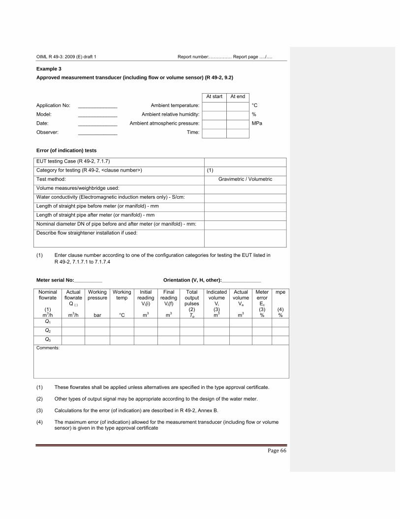
OIML R 49-3: 2009 (E) draft 1 Report number:…………… Report page …./….
Page 66
Example 3 Approved measurement transducer (including flow or volume sensor) (R 49-2, 9.2) At start At end
Application No: ______________ Ambient temperature: °C
Model: ______________ Ambient relative humidity: %
Date: ______________ Ambient atmospheric pressure: MPa
Observer: ______________ Time: Error (of indication) tests EUT testing Case (R 49-2, 7.1.7)
Category for testing (R 49-2, <clause number>) (1)
Test method: Gravimetric / Volumetric
Volume measures/weighbridge used:
Water conductivity (Electromagnetic induction meters only) - S/cm:
Length of straight pipe before meter (or manifold) - mm
Length of straight pipe after meter (or manifold) - mm
Nominal diameter DN of pipe before and after meter (or manifold) - mm:
Describe flow straightener installation if used:
(1) Enter clause number according to one of the configuration categories for testing the EUT listed in
R 49-2, 7.1.7.1 to 7.1.7.4
Meter serial No:__________ Orientation (V, H, other):______________
Nominal flowrate
(1)
m3/h
Actual flowrate
Q ( )
m3/h
Working pressure
bar
Working temp
°C
Initial reading
Vi(i)
m3
Final reading
Vi(f)
m3
Total output pulses
(2) Tp
Indicatedvolume
Vi (3) m3
Actual volume
Va
m3
Meter error
Ec (3) %
mpe
(4) %
Q1
Q2
Q3
Comments:
(1) These flowrates shall be applied unless alternatives are specified in the type approval certificate. (2) Other types of output signal may be appropriate according to the design of the water meter. (3) Calculations for the error (of indication) are described in R 49-2, Annex B. (4) The maximum error (of indication) allowed for the measurement transducer (including flow or volume
sensor) is given in the type approval certificate
OIML R 49-3: 2009 (E) draft 1 Report number:…………… Report page …./….
Page 67
ANNEX A (Mandatory)
List of documents concerning the type
(R 49-1, 6.2.9.1) Document reference Date Brief description
OIML R 49-3: 2009 (E) draft 1 Report number:…………… Report page …./….
Page 68
ANNEX B (Mandatory)
Listing of test equipment used in examinations and tests
Parameter
measured or applied
Instrument/ equipment
Model number
Serial number
Calibration date Used in test No. (R 49-2, section No.) Last Next
Comments:

12/15/2009 8:15:00 PM
12/15/2009 8:15:00 PM
12/15/2009 8:15:00 PM
12/15/2009 8:15:00 PM
12/15/2009 8:15:00 PM

12/15/2009 8:15:00 PM
12/15/2009 8:15:00 PM
12/15/2009 8:15:00 PM
12/15/2009 8:15:00 PM
12/15/2009 8:15:00 PM
12/15/2009 8:15:00 PM
12/15/2009 8:15:00 PM
12/15/2009 8:15:00 PM
12/15/2009 8:15:00 PM
12/15/2009 8:15:00 PM

12/15/2009 8:15:00 PM
12/15/2009 8:15:00 PM
12/15/2009 8:15:00 PM
12/15/2009 8:15:00 PM
12/15/2009 8:15:00 PM

12/15/2009 8:15:00 PM
12/15/2009 8:15:00 PM
12/15/2009 8:15:00 PM
12/15/2009 8:15:00 PM
12/15/2009 8:15:00 PM
12/15/2009 8:15:00 PM
12/15/2009 8:15:00 PM
12/15/2009 8:15:00 PM
12/15/2009 8:15:00 PM
12/15/2009 8:15:00 PM

12/15/2009 8:15:00 PM
12/15/2009 8:15:00 PM
12/15/2009 8:15:00 PM
12/15/2009 8:15:00 PM
12/15/2009 8:15:00 PM

12/15/2009 8:15:00 PM
12/15/2009 8:15:00 PM
12/15/2009 8:15:00 PM
12/15/2009 8:15:00 PM


![Br oiml weights_es[1]](https://img.pdfslide.tips/doc/110x75/58d165741a28aba3468b5e1b/br-oiml-weightses1.jpg)