Embed Size (px)
Citation preview
Reference numberISO 1940-1:2003(E)
© ISO 2003
INTERNATIONAL STANDARD
ISO1940-1
Second edition2003-08-15
Mechanical vibration — Balance quality requirements for rotors in a constant (rigid) state — Part 1: Specification and verification of balance tolerances
Vibrations mécaniques — Exigences en matière de qualité dans l'équilibrage pour les rotors en état rigide (constant) —
Partie 1: Spécifications et vérification des tolérances d'équilibrage
ISO 1940-1:2003(E)
PDF disclaimer This PDF file may contain embedded typefaces. In accordance with Adobe's licensing policy, this file may be printed or viewed but shall not be edited unless the typefaces which are embedded are licensed to and installed on the computer performing the editing. In downloading this file, parties accept therein the responsibility of not infringing Adobe's licensing policy. The ISO Central Secretariat accepts no liability in this area.
Adobe is a trademark of Adobe Systems Incorporated.
Details of the software products used to create this PDF file can be found in the General Info relative to the file; the PDF-creation parameters were optimized for printing. Every care has been taken to ensure that the file is suitable for use by ISO member bodies. In the unlikely event that a problem relating to it is found, please inform the Central Secretariat at the address given below.
© ISO 2003 All rights reserved. Unless otherwise specified, no part of this publication may be reproduced or utilized in any form or by any means, electronic or mechanical, including photocopying and microfilm, without permission in writing from either ISO at the address below or ISO's member body in the country of the requester.
ISO copyright office Case postale 56 • CH-1211 Geneva 20 Tel. + 41 22 749 01 11 Fax + 41 22 749 09 47 E-mail [email protected] Web www.iso.org
Published in Switzerland
ii © ISO 2003 — All rights reserved
ISO 1940-1:2003(E)
© ISO 2003 — All rights reserved iii
Contents Page
Foreword............................................................................................................................................................. v Introduction ....................................................................................................................................................... vi 1 Scope...................................................................................................................................................... 1 2 Normative references ........................................................................................................................... 1 3 Terms and definitions........................................................................................................................... 2 4 Pertinent aspects of balancing............................................................................................................ 4 4.1 General ................................................................................................................................................... 4 4.2 Representation of the unbalance ........................................................................................................ 4 4.3 Unbalance effects ................................................................................................................................. 6 4.4 Reference planes for balance tolerances ........................................................................................... 6 4.5 Correction planes.................................................................................................................................. 6 4.6 Permissible residual unbalance .......................................................................................................... 7 5 Similarity considerations ..................................................................................................................... 8 5.1 General ................................................................................................................................................... 8 5.2 Permissible residual unbalance and rotor mass ............................................................................... 8 5.3 Permissible residual specific unbalance and service speed ........................................................... 8 6 Specification of balance tolerances.................................................................................................... 9 6.1 General ................................................................................................................................................... 9 6.2 Balance quality grades G ..................................................................................................................... 9 6.3 Experimental evaluation..................................................................................................................... 10 6.4 Methods based on special aims ........................................................................................................ 13 6.5 Methods based on established experience...................................................................................... 13 7 Allocation of permissible residual unbalance to tolerance planes ............................................... 13 7.1 Single plane ......................................................................................................................................... 13 7.2 Two planes........................................................................................................................................... 13 8 Allocation of balance tolerances to correction planes ................................................................... 15 8.1 General ................................................................................................................................................. 15 8.2 Single plane ......................................................................................................................................... 15 8.3 Two planes........................................................................................................................................... 16 9 Assembled rotors................................................................................................................................ 16 9.1 General ................................................................................................................................................. 16 9.2 Balanced as a unit............................................................................................................................... 16 9.3 Balanced on component level ........................................................................................................... 16 10 Verification of residual unbalance .................................................................................................... 16 10.1 General ................................................................................................................................................. 16 10.2 Acceptance criteria ............................................................................................................................. 17 10.3 Verification on a balancing machine................................................................................................. 17 10.4 Verification outside a balancing machine ........................................................................................ 17 Annex A (informative) Example of the specification of permissible residual unbalance based on
balance quality grade G and allocation to the tolerance planes.................................................... 19 Annex B (informative) Specification of balance tolerances based on bearing force limits...................... 22 Annex C (informative) Specification of balance tolerances based on vibration limits ............................. 23 Annex D (informative) Specification of balance tolerances based on established experience ............... 24
ISO 1940-1:2003(E)
iv © ISO 2003 — All rights reserved
Annex E (informative) Rules for allocating balance tolerances from tolerance planes to correction planes ...................................................................................................................................................26
Bibliography......................................................................................................................................................28
ISO 1940-1:2003(E)
© ISO 2003 — All rights reserved v
Foreword
ISO (the International Organization for Standardization) is a worldwide federation of national standards bodies (ISO member bodies). The work of preparing International Standards is normally carried out through ISO technical committees. Each member body interested in a subject for which a technical committee has been established has the right to be represented on that committee. International organizations, governmental and non-governmental, in liaison with ISO, also take part in the work. ISO collaborates closely with the International Electrotechnical Commission (IEC) on all matters of electrotechnical standardization.
International Standards are drafted in accordance with the rules given in the ISO/IEC Directives, Part 2.
The main task of technical committees is to prepare International Standards. Draft International Standards adopted by the technical committees are circulated to the member bodies for voting. Publication as an International Standard requires approval by at least 75 % of the member bodies casting a vote.
Attention is drawn to the possibility that some of the elements of this document may be the subject of patent rights. ISO shall not be held responsible for identifying any or all such patent rights.
ISO 1940-1 was prepared by Technical Committee ISO/TC 108, Mechanical vibration and shock, Subcommittee SC 1, Balancing, including balancing machines.
This second edition cancels and replaces the first edition (ISO 1940-1:1986), which has been technically revised. The most important change is the introduction of reference planes for balance tolerances instead of using the correction planes as tolerance planes.
ISO 1940 consists of the following parts, under the general title Mechanical vibration — Balance quality requirements for rotors in a constant (rigid) state:
Part 1: Specification and verification of balance tolerances
Part 2: Balance errors
ISO 1940-1:2003(E)
vi © ISO 2003 — All rights reserved
Introduction
A general introduction to balancing standards will be given in ISO 19499 (under preparation). For rotors in a constant (rigid) state, only the resultant unbalance and the resultant moment unbalance (resultant couple unbalance) are of interest, both together often expressed as dynamic unbalance.
The balancing machines available today enable unbalance to be reduced to low limits. However, it would be uneconomical to reduce the unbalances to these limits. On the contrary, it is necessary to specify the balance quality requirement for any balancing task.
Of similar importance is the verification of residual unbalances. For this verification, different balance errors have to be taken into account. An improved procedure to handle errors of the balancing machine is described in connection with ISO 1940-2.
INTERNATIONAL STANDARD ISO 1940-1:2003(E)
© ISO 2003 — All rights reserved 1
Mechanical vibration — Balance quality requirements for rotors in a constant (rigid) state —
Part 1: Specification and verification of balance tolerances
1 Scope
This part of ISO 1940 gives specifications for rotors in a constant (rigid) state. It specifies
a) balance tolerances,
b) the necessary number of correction planes, and
c) methods for verifying the residual unbalance.
Recommendations are also given concerning the balance quality requirements for rotors in a constant (rigid) state, according to their machinery type and maximum service speed. These recommendations are based on worldwide experience.
This part of ISO 1940 is also intended to facilitate the relationship between the manufacturer and user of rotating machines, by stating acceptance criteria for the verification of residual unbalances.
Detailed consideration of errors associated with balancing and verification of residual unbalance are given in ISO 1940-2.
This part of ISO 1940 does not cover rotors in a flexible state. The balance quality requirements for rotors in a flexible state are covered by ISO 11342.
2 Normative references
The following referenced documents are indispensable for the application of this document. For dated references, only the edition cited applies. For undated references, the latest edition of the referenced document (including any amendments) applies.
ISO 1925:2001, Mechanical vibration — Balancing — Vocabulary
ISO 1940-2, Mechanical vibration — Balance quality requirements of rigid rotors — Part 2: Balance errors
ISO 1940-1:2003(E)
2 © ISO 2003 — All rights reserved
3 Terms and definitions
For the purposes of this document, the terms and definitions given in ISO 1925 apply. For the convenience of users, some of these definitions are cited below.
NOTE Some of these definitions are at present under review.
3.1 balancing procedure by which the mass distribution of a rotor is checked and, if necessary, adjusted to ensure that the residual unbalance or the vibration of the journals and/or forces on the bearings at a frequency corresponding to service speed are within specified limits
[ISO 1925:2001, definition 4.1]
3.2 unbalance condition which exists in a rotor when vibration force or motion is imparted to its bearings as a result of centrifugal forces
[ISO 1925:2001, definition 3.1]
3.3 initial unbalance unbalance of any kind that exists in the rotor before balancing
[ISO 1925:2001, definition 3.11]
3.4 residual unbalance final unbalance unbalance of any kind that remains after balancing
[ISO 1925:2001, definition 3.10]
3.5 resultant unbalance vector sum of all unbalance vectors distributed along the rotor
NOTE 1 See notes to definition 3.6.
[ISO 1925:2001, definition 3.12]
NOTE 2 This can be expressed as
r1
Kk
kU U
=
= ∑
where
rU is the resultant unbalance vector (g⋅mm);
kU are the individual unbalance vectors, numbered 1 to K.
3.6 resultant moment unbalance vector sum of the moments of all the unbalance vectors distributed along the rotor about the plane of the resultant unbalance
ISO 1940-1:2003(E)
© ISO 2003 — All rights reserved 3
NOTE 1 The resultant unbalance together with the resultant moment unbalance describe completely the unbalance of a rotor in a constant (rigid) state.
NOTE 2 The resultant unbalance vector is not related to a particular radial plane, but the amount and angular direction of the resultant moment unbalance depend on the axial location chosen for the resultant unbalance.
NOTE 3 The resultant unbalance vector is the vector sum of the complementary unbalance vectors of the dynamic unbalance.
NOTE 4 The resultant moment unbalance is often expressed as a pair of unbalance vectors of equal magnitude, but opposite directions, in any two different radial planes.
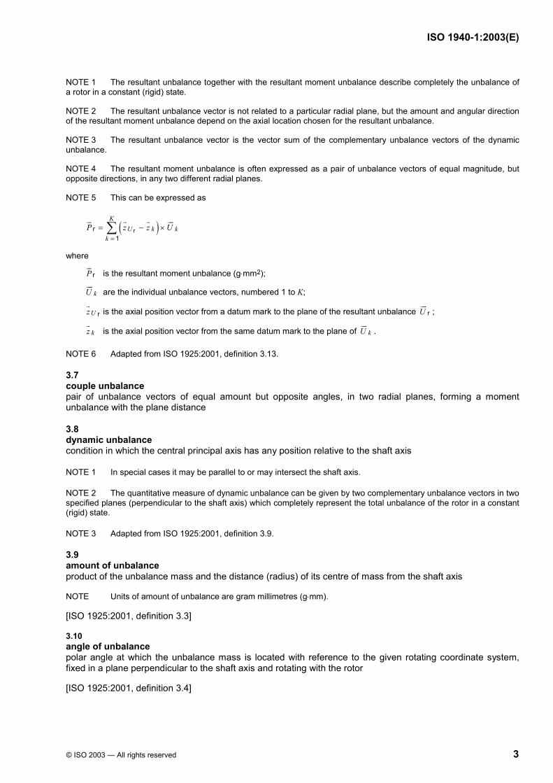
NOTE 5 This can be expressed as
( )rr1
KU k k
kP z z U
=
= − ×∑
where
rP is the resultant moment unbalance (g⋅mm2);
kU are the individual unbalance vectors, numbered 1 to K;
rUz is the axial position vector from a datum mark to the plane of the resultant unbalance rU ;
kz is the axial position vector from the same datum mark to the plane of kU .
NOTE 6 Adapted from ISO 1925:2001, definition 3.13.
3.7 couple unbalance pair of unbalance vectors of equal amount but opposite angles, in two radial planes, forming a moment unbalance with the plane distance
3.8 dynamic unbalance condition in which the central principal axis has any position relative to the shaft axis
NOTE 1 In special cases it may be parallel to or may intersect the shaft axis.
NOTE 2 The quantitative measure of dynamic unbalance can be given by two complementary unbalance vectors in two specified planes (perpendicular to the shaft axis) which completely represent the total unbalance of the rotor in a constant (rigid) state.
NOTE 3 Adapted from ISO 1925:2001, definition 3.9.
3.9 amount of unbalance product of the unbalance mass and the distance (radius) of its centre of mass from the shaft axis
NOTE Units of amount of unbalance are gram millimetres (g⋅mm).
[ISO 1925:2001, definition 3.3]
3.10 angle of unbalance polar angle at which the unbalance mass is located with reference to the given rotating coordinate system, fixed in a plane perpendicular to the shaft axis and rotating with the rotor
[ISO 1925:2001, definition 3.4]
ISO 1940-1:2003(E)
4 © ISO 2003 — All rights reserved
3.11 unbalance vector vector whose magnitude is the amount of unbalance and whose direction is the angle of unbalance
[ISO 1925:2001, definition 3.5]
3.12 state of a rotor state determined by the unbalance behaviour with speed, the types of unbalance to be corrected, and the ability of the rotor to maintain or to change the position of its mass elements and their centres of mass relative to each other within the speed range
NOTE 1 Unbalances in most cases to not change considerably with speed. Contrary to the definitions used up to now (ISO 1925) even modal unbalances are not speed dependent. Only a special cases do unbalances change considerably with speed.
NOTE 2 Mass elements are useful means to describe the mass distribution of a rotor and possible changes with speed. Mass elements can be finite elements, or parts or components.
NOTE 3 The rotor state is also influenced by its design, construction and assembly.
NOTE 4 The response of the rotor to unbalance can change with the speed range and its bearing support conditions. The acceptability of the response is determined by the relevant balance tolerances.
NOTE 5 The speed range covers all speeds from standstill to the maximum service speed, but can also include an overspeed as a margin for service loads (e.g. temperature, pressure, flow).
NOTE 6 With regard to balancing, only changes in the position of rotor mass elements not symmetric to the shaft axis need to be considered.
3.13 constant (rigid) rotor state state of a rotor where the unbalances are not changing considerably with speed, only the resultant unbalance and/or the resultant moment unbalance are out of specified limits, and the position of all mass elements of the rotor relative to each other remains sufficiently constant within the speed range
NOTE The unbalance of a rotor in its constant state can be corrected in any two (arbitrarily selected) planes.
4 Pertinent aspects of balancing
4.1 General
Balancing is a procedure by which the mass distribution of a rotor is checked and, if necessary, adjusted to ensure that the residual unbalance or the vibration of the journals and/or forces at the bearings at a frequency corresponding to service speed are within specified limits.
Rotor unbalance can be caused by design, material, manufacturing and assembly. Every rotor has an individual unbalance distribution along its length, even in a series production.
4.2 Representation of the unbalance
One and the same unbalance of a rotor in a constant (rigid) state can be represented by vectorial quantities in various ways, as shown in Figures 1a) to 1f).
Figures 1a) to 1c) show different representations in terms of resultant unbalance and resultant couple unbalance, whereas Figures 1d) to 1f) are in terms of a dynamic unbalance in two planes.
NOTE 1 The resultant unbalance vector may be located in any radial plane (without changing amount and angle); but the associated resultant couple unbalance is dependent on the location of the resultant unbalance vector.
ISO 1940-1:2003(E)
© ISO 2003 — All rights reserved 5
NOTE 2 The centre of unbalance is that location on the shaft axis for the resultant unbalance, where the resultant moment unbalance is a minimum.
If single-plane balancing is sufficient (see 4.5.2), or when considerations are made in terms of resultant/couple unbalance (see 4.5.4), the representation in Figures 1a) to 1c) is preferable. In the case of typical two-plane considerations, the representation in Figures 1d) to 1f) will be advantageous.
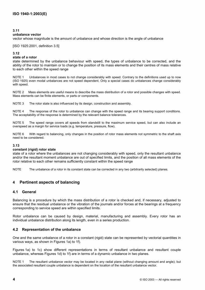
Dimensions in millimetres
a) A resultant unbalance vector together with an associated couple unbalance in the end planes
b) Special case of a), namely unbalance vector located at mass centre CM (static unbalance), together with an associated couple unbalance in the end planes
c) Special case of a), namely resultant unbalance vector located at the centre of unbalance CU. The associated couple unbalance is a minimum and lays in a plane orthogonal to the resultant unbalance vector
d) An unbalance vector in each of the end planes
ISO 1940-1:2003(E)
6 © ISO 2003 — All rights reserved
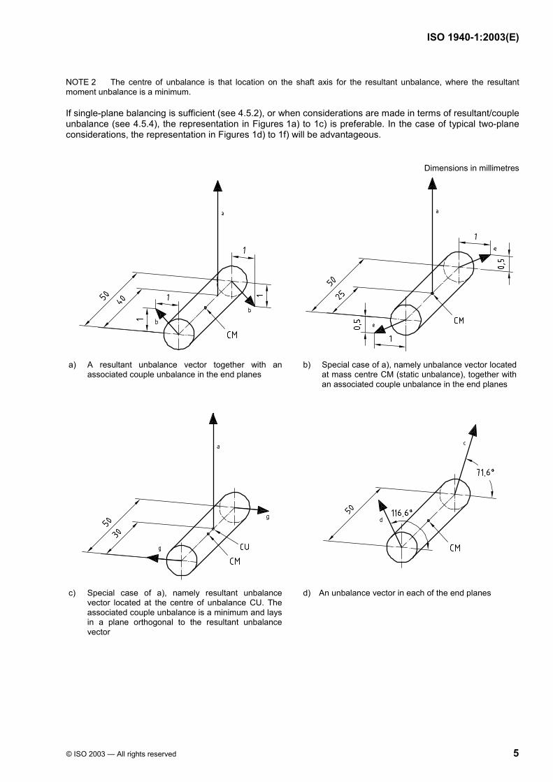
e) Two 90° unbalance components in each of the end planes
f) An unbalance vector in each of two other planes
a Unbalance is 5 g⋅mm. b Unbalance is 1,41 g⋅mm. c Unbalance is 3,16 g⋅mm. d Unbalance is 2,24 g⋅mm. e Unbalance is 1,12 g⋅mm.
f Unbalance is 3 g⋅mm. g Unbalance is 1 g⋅mm. h Unbalance is 2 g⋅mm. i Unbalance is 2,69 g⋅mm.
CM is the centre of mass.
CU is the centre of unbalance.
Figure 1 — Different representations of the same unbalance of a rotor in a constant (rigid) state
4.3 Unbalance effects
Resultant unbalance and resultant moment unbalance (resultant couple unbalance) have different effects on forces on the bearings and on the vibration of the machine. In practice, therefore, both unbalances are often considered separately. Even if the unbalance is stated as a dynamic unbalance in two planes, it should be noted that in most cases there will be a difference in effects if the unbalances dominantly form either a resultant unbalance or a resultant couple unbalance.
4.4 Reference planes for balance tolerances
It is desirable to use special reference planes to state balance tolerances. For these planes, only the magnitude of each residual unbalance must stay below the respective tolerance value, whatever the angular position may be.
There are always two ideal planes for balance tolerances for a rotor in a constant (rigid) state. In most cases these planes are near to the bearing planes. Moreover, the aim of balancing is usually to reduce vibrations and forces transmitted through the bearings to the environment. In order to facilitate this approach, this part of ISO 1940 takes the bearing planes A and B as reference planes for balance tolerances (tolerance planes).
4.5 Correction planes
4.5.1 General
Rotors out of balance tolerance need correction. These unbalance corrections often cannot be performed in the planes where the balance tolerances were set, but need to be performed where material can be added, removed or relocated.
ISO 1940-1:2003(E)
© ISO 2003 — All rights reserved 7
The number of necessary correction planes depends on the magnitude and distribution of the initial unbalance as well as on the design of the rotor, for instance the shape of the correction planes and their location relative to the tolerance planes.
4.5.2 Rotors which need one correction plane only
For some rotors, only the resultant unbalance is out of tolerance, the resultant moment unbalance is in tolerance. This typically happens with disc-shaped rotors, provided that
the bearing distance is sufficiently large,
the disc rotates with sufficiently small axial runout, and
the correction plane for the resultant unbalance is properly chosen.
Whether these conditions are fulfilled may be investigated in each individual case. After single-plane balancing has been carried out on a sufficient number of rotors, the largest residual moment unbalance is determined and divided by the bearing distance, yielding a couple unbalance (pair of unbalances). If, even in the worst case, the unbalances found this way are acceptable, it can be expected that a single-plane balancing is sufficient.
For single-plane balancing, the rotor needs not rotate but, for sensitivity and accuracy reasons, in most cases rotational balancing machines are used. The resultant unbalance can be determined and corrected to limits.
4.5.3 Rotors which need two correction planes
If a rotor in a constant (rigid) state does not comply with the conditions as stated in 4.5.2, the moment unbalance needs to be reduced as well. In most cases, resultant unbalance and resultant moment unbalance are assembled into a dynamic unbalance: two unbalance vectors in two planes [see Figure 1d)], called complementary unbalance vectors.
For two-plane balancing, it is necessary for the rotor to rotate, since otherwise the moment unbalance would remain undetected.
4.5.4 Rotors with more than two correction planes
Although all rotors in their constant (rigid) state theoretically can be balanced in two planes, sometimes more than two correction planes are used, for instance
in the case of separate corrections of resultant unbalance and couple unbalance, if the correction of the resultant unbalance is not performed in one (or both) of the couple planes, and
if the correction is spread along the rotor.
NOTE In special cases, spreading the correction along the rotor may be necessary due to restrictions in the correction planes (e.g. correction of crankshafts by drilling into the counterweights), or advisable in order to keep function and component strength.
4.6 Permissible residual unbalance
In the simple case of an inboard rotor with small axial length, for which the couple unbalance may be ignored, its unbalance state can then be described as a single vectorial quantity, the unbalance .U
To obtain a satisfactory running of the rotor, the magnitude of this unbalance (the residual unbalance Ures) should not be higher than a permissible value Uper, i.e.
Ures u Uper (1)
More generally, the same applies to any type of rotor.
ISO 1940-1:2003(E)
8 © ISO 2003 — All rights reserved
NOTE The SI unit for Uper is kilogram metres (kg⋅m), but for balancing purposes a more practical unit is gram millimetres (g⋅mm).
Uper is defined as the total tolerance in the mass centre plane. For all two-plane tasks, this tolerance shall be allocated to the tolerance planes (see Clause 7).
5 Similarity considerations
5.1 General
Some considerations on similarity may help in the understanding and calculation of the influences of rotor mass and service speed on the permissible residual unbalance.
5.2 Permissible residual unbalance and rotor mass
In general, for rotors of the same type, the permissible residual unbalance Uper is proportional to the rotor mass m:
Uper ∼ m (2)
If the value of the permissible residual unbalance is related to the rotor mass, the result is the permissible residual specific unbalance eper, as given by the following equation:
eper = Uper/m (3)
NOTE 1 The SI unit for Uper/m is kilogram metres per kilogram (kg⋅m/kg), but a more practical unit is gram millimetres per kilogram (g⋅mm/kg), which corresponds to micrometres in Note 2.
NOTE 2 The SI unit for eper is kilogram metres per kilogram (kg⋅m/kg) or metres (m). A more practical unit is micrometres (µm) because many permissible residual specific unbalances are between 0,1 µm and 10 µm. The term eper is useful especially if one has to relate geometric tolerances (runout, play) to balance tolerances.
NOTE 3 In the case of a rotor with only a resultant unbalance (e.g. a disc, perpendicular to the shaft axis), eper is the distance of the mass centre from the shaft axis. In the case of a general rotor with both types of unbalance, eper is an artificial quantity containing the effects of the resulting unbalance as well as of the resultant moment unbalance. Therefore eper cannot be seen on a general rotor.
NOTE 4 There are limits for achievable residual specific unbalance eper depending on the set-up conditions in the balancing machine, for instance: centring, bearings and drive.
NOTE 5 Small values of eper can only be achieved in practice if the accuracy of shaft journals (roundness, straightness, etc.) is adequate. In some cases it may be necessary to balance the rotor in its own service bearings, using belt-, air- or self-drive. In other cases balancing needs to be carried out with the rotor completely assembled in its own housing with bearings and self-drive, under service condition and temperature.
5.3 Permissible residual specific unbalance and service speed
For rotors of the same type, experience shows that, in general, the permissible residual specific unbalance value eper varies inversely with the service speed n of the rotor:
eper ∼ 1/n (4)
Differently expressed, this relationship is given by the following equation, where Ω is the angular velocity of the rotor at maximum service speed:
eper⋅Ω = constant (5)
ISO 1940-1:2003(E)
© ISO 2003 — All rights reserved 9
This relationship follows also from the fact that for geometrically similar rotors running at equal peripheral velocities, the stresses in the rotors and the bearing specific loads (due to centrifugal forces) are the same. The balance quality grades (see 6.2, Table 1 and Figure 2) are based on this relationship.
NOTE For rotors with a service speed significantly lower than the maximum speed for which the rotor was designed (e.g. some types of a.c. motors designed for 3 000 r/min, used in a 1 000 r/min stator), this similarity rule can be too restrictive. In such cases a higher value of eper may be admitted (proportional to 3 000/1 000).
6 Specification of balance tolerances
6.1 General
The balance tolerances may be determined by five different methods as described in 6.2 to 6.5. The methods are based on
balance quality grades, derived from long-term practical experience with a large number of different rotors (see 6.2),
experimental evaluation of permissible unbalance limits (see 6.3),
limited bearing forces due to unbalance (see 6.4.1),
limited vibrations due to unbalance (see 6.4.2), and
established experience with balance tolerances (see 6.5).
The choice of method should be agreed between the manufacturer and user of the rotor.
6.2 Balance quality grades G
6.2.1 Classification
On the basis of worldwide experience and similarity considerations (see Clause 5), balance quality grades G have been established which permit a classification of the balance quality requirements for typical machinery types (see Table 1).
Balance quality grades G are designated according to the magnitude of the product eper Ω expressed in millimetres per second (mm/s). If the magnitude is equal to 6,3 mm/s, the balance quality grade is designated G 6,3.
Balance quality grades are separated from each other by a factor of 2,5. A finer grading may be necessary in some cases, especially when high-precision balancing is required, but it should not be less than a factor of 1,6.
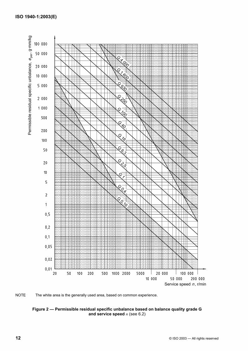
The values of eper (identical to Uper/m) are plotted against the maximum service speed in Figure 2.
NOTE Figure 2 contains some additional information on generally used areas (speed and quality grade G), based on common experience.
6.2.2 Special designs
The balance quality grades are based on typical machine design, where the rotor mass is a certain fraction of the complete machine. In special cases modifications are needed.
EXAMPLE Electric motors of shaft heights smaller than 80 mm are grouped to G 6,3 and the permissible unbalance will be derived from this class (see 6.2.3). This permissible unbalance value is applicable, as long as the rotor mass is a typical percentage of the machine mass, for instance 30 %. In the case of light-weight rotors (such as an iron-less armatures), the rotor mass may be only 10 % of the total mass. As a result, three times the permissible unbalance may be allowed.
On the contrary, if the rotor mass is extremely high (in the case of an external-rotor motor), it may be up to 90 %. The permissible unbalance may need to be reduced by a factor of 3.
ISO 1940-1:2003(E)
10 © ISO 2003 — All rights reserved
6.2.3 Permissible residual unbalance
The permissible residual unbalance Uper can be derived on the basis of a selected balance quality grade G by the following equation:
( )perper 1 000
e m = U
Ω
Ω
⋅ ⋅ (6)
where
Uper is the numerical value of the permissible residual unbalance, expressed in gram millimetres (g⋅mm);
(eper⋅Ω) is the numerical value of the selected balance quality grade, expressed in millimetres per second (mm/s);
m is the numerical value of the rotor mass, expressed in kilograms (kg);
Ω is the numerical value of the angular velocity of the service speed, expressed in radians per second (rad/s), with Ω ≈ n/10 and the service speed n in revolutions per minute (r/min).
As an alternative, Figure 2 may be used to derive eper, then:
per per = e mU ⋅ (7)
NOTE For the permissible residual unbalance Uper, the balance quality grade (eper⋅ Ω), and permissible residual specific unbalance eper, the SI units are used here with prefixes, so special care is needed to apply this equation. An example is given in Annex A.
Uper is defined as the total tolerance in the mass centre plane. For all two-plane tasks, this tolerance shall be allocated to the tolerance planes (see Clause 7).
6.3 Experimental evaluation
Experimental evaluation of the balance quality requirements is often carried out for mass production applications. Tests are commonly performed in situ. The permissible residual unbalance is determined by introducing various test unbalances successively in each correction plane, based on the most representative criterion (e.g. vibration, force, noise caused by unbalance).
In two-plane balancing, if no tolerance planes (as specified in 4.4) are used, the different effects of unbalances with the same phase angle and of those 180° apart shall be taken into account.
ISO 1940-1:2003(E)
© ISO 2003 — All rights reserved 11
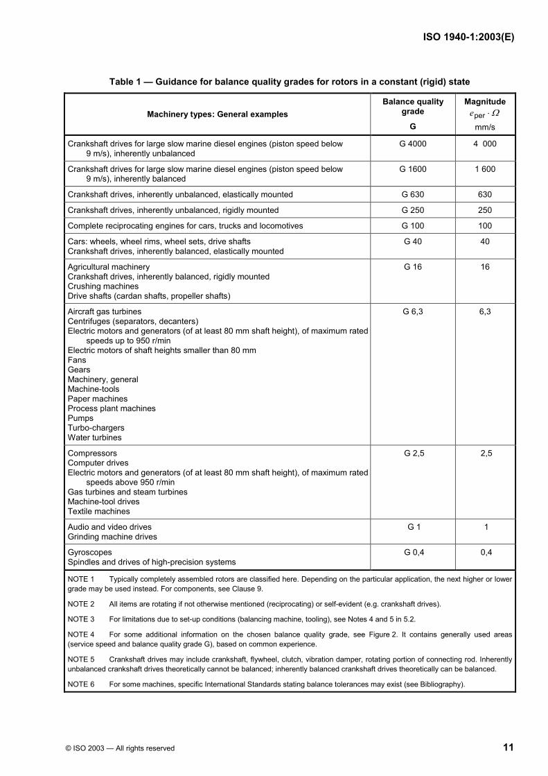
Table 1 — Guidance for balance quality grades for rotors in a constant (rigid) state
Machinery types: General examples Balance quality
grade
G
Magnitude pere Ω⋅
mm/s
Crankshaft drives for large slow marine diesel engines (piston speed below 9 m/s), inherently unbalanced
G 4000 4 000
Crankshaft drives for large slow marine diesel engines (piston speed below 9 m/s), inherently balanced
G 1600 1 600
Crankshaft drives, inherently unbalanced, elastically mounted G 630 630
Crankshaft drives, inherently unbalanced, rigidly mounted G 250 250
Complete reciprocating engines for cars, trucks and locomotives G 100 100
Cars: wheels, wheel rims, wheel sets, drive shafts Crankshaft drives, inherently balanced, elastically mounted
G 40 40
Agricultural machinery Crankshaft drives, inherently balanced, rigidly mounted Crushing machines Drive shafts (cardan shafts, propeller shafts)
G 16 16
Aircraft gas turbines Centrifuges (separators, decanters) Electric motors and generators (of at least 80 mm shaft height), of maximum rated
speeds up to 950 r/min Electric motors of shaft heights smaller than 80 mm Fans Gears Machinery, general Machine-tools Paper machines Process plant machines Pumps Turbo-chargers Water turbines
G 6,3 6,3
Compressors Computer drives Electric motors and generators (of at least 80 mm shaft height), of maximum rated
speeds above 950 r/min Gas turbines and steam turbines Machine-tool drives Textile machines
G 2,5 2,5
Audio and video drives Grinding machine drives
G 1 1
Gyroscopes Spindles and drives of high-precision systems
G 0,4 0,4
NOTE 1 Typically completely assembled rotors are classified here. Depending on the particular application, the next higher or lower grade may be used instead. For components, see Clause 9.
NOTE 2 All items are rotating if not otherwise mentioned (reciprocating) or self-evident (e.g. crankshaft drives).
NOTE 3 For limitations due to set-up conditions (balancing machine, tooling), see Notes 4 and 5 in 5.2.
NOTE 4 For some additional information on the chosen balance quality grade, see Figure 2. It contains generally used areas (service speed and balance quality grade G), based on common experience.
NOTE 5 Crankshaft drives may include crankshaft, flywheel, clutch, vibration damper, rotating portion of connecting rod. Inherently unbalanced crankshaft drives theoretically cannot be balanced; inherently balanced crankshaft drives theoretically can be balanced.
NOTE 6 For some machines, specific International Standards stating balance tolerances may exist (see Bibliography).
ISO 1940-1:2003(E)
12 © ISO 2003 — All rights reserved
NOTE The white area is the generally used area, based on common experience.
Figure 2 — Permissible residual specific unbalance based on balance quality grade G and service speed n (see 6.2)
ISO 1940-1:2003(E)
© ISO 2003 — All rights reserved 13
6.4 Methods based on special aims
6.4.1 Limited bearing forces
The main objective may be to limit the bearing forces caused by unbalances. The limits are stated first in terms of bearing forces, but then need transformation into unbalances. In the case of a sufficiently steady (not moving) bearing housing, this transformation simply uses the equation for the centrifugal force (see Annex B).
In all other cases, the dynamic behaviour of the structure under service condition shall be considered. There are no simple rules available for these cases.
6.4.2 Limited vibrations
The main objective in this case is to limit vibrations in certain planes. This may be of interest for instance for hand-held machines. Balance quality requirements can be derived from these limits (see Annex C).
6.5 Methods based on established experience
If a company has gained sufficient established experience to assess the balance quality of its products, it may make full use of this. Annex D gives some guidance.
7 Allocation of permissible residual unbalance to tolerance planes
7.1 Single plane
In the case of single-plane correction, Uper is used entirely for this plane (see 4.5.2). In all other cases, Uper shall be allocated to the two tolerance planes.
7.2 Two planes
7.2.1 General
The permissible residual unbalance Uper is allocated in proportion to the distances from the mass centre to the opposite tolerance plane (see Figures 3 and 4). If the tolerance planes are the bearing planes A and B, the following equations apply:
Bperper A
U L = U L
⋅ (8)
Aperper B
U L = U L
⋅ (9)
where
Uper A is the permissible residual unbalance in bearing plane A;
Uper B is the permissible residual unbalance in bearing plane B;
Uper is the (total) permissible residual unbalance (in the mass centre plane);
LA is the distance from mass centre plane to bearing plane A;
LB is the distance from mass centre plane to bearing plane B;
L is the bearing span.
ISO 1940-1:2003(E)
14 © ISO 2003 — All rights reserved
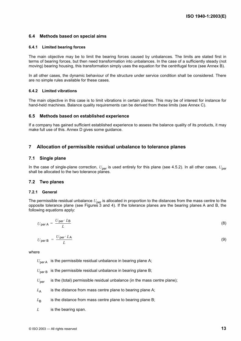
7.2.2 Limitations for inboard rotors
For general outlines, see Figure 3. If the mass centre is near to one bearing, the calculated tolerance for this bearing becomes very large, near to the value of Uper, and the value for the remote bearing will become very small, near to zero. To avoid extreme tolerance conditions, it is stipulated that
the larger value should not be larger than 0,7 Uper, and
the smaller value should not be smaller than 0,3 Uper.
Key 1 tolerance planes (= bearing planes) CM is the centre of mass.
Figure 3 — Inboard rotor with mass centre in an asymmetric position
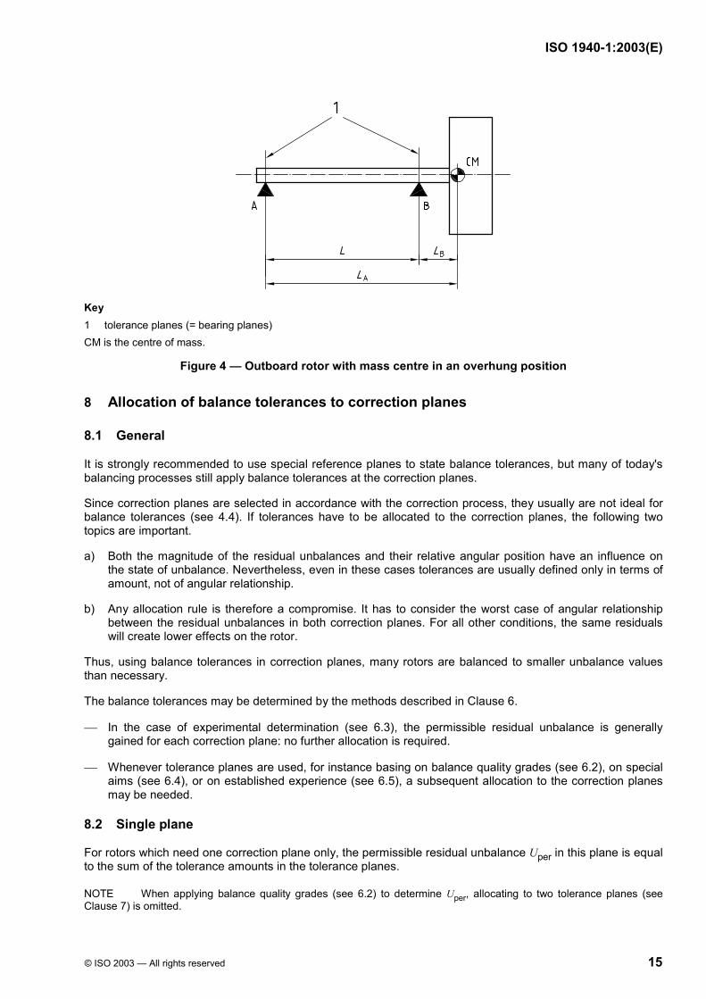
7.2.3 Limitations for outboard rotors
For general outlines, see Figure 4. The values are calculated according to Equations (8) and (9). However, to avoid extreme tolerance conditions, it is stipulated that
the larger value should not be larger than 1,3 Uper, and
the smaller value should not be smaller than 0,3 Uper.
The upper unbalance limit is different from that of the inboard rotor. This assumes that bearing B and the supporting structure are designed to take the static load exerted by the overhung mass. Thus it will also support a proportionately higher load caused by unbalances. If this is not the case, the limitations for inboard rotors should be applied.
ISO 1940-1:2003(E)
© ISO 2003 — All rights reserved 15
Key 1 tolerance planes (= bearing planes) CM is the centre of mass.
Figure 4 — Outboard rotor with mass centre in an overhung position
8 Allocation of balance tolerances to correction planes
8.1 General
It is strongly recommended to use special reference planes to state balance tolerances, but many of today's balancing processes still apply balance tolerances at the correction planes.
Since correction planes are selected in accordance with the correction process, they usually are not ideal for balance tolerances (see 4.4). If tolerances have to be allocated to the correction planes, the following two topics are important.
a) Both the magnitude of the residual unbalances and their relative angular position have an influence on the state of unbalance. Nevertheless, even in these cases tolerances are usually defined only in terms of amount, not of angular relationship.
b) Any allocation rule is therefore a compromise. It has to consider the worst case of angular relationship between the residual unbalances in both correction planes. For all other conditions, the same residuals will create lower effects on the rotor.
Thus, using balance tolerances in correction planes, many rotors are balanced to smaller unbalance values than necessary.
The balance tolerances may be determined by the methods described in Clause 6.
In the case of experimental determination (see 6.3), the permissible residual unbalance is generally gained for each correction plane: no further allocation is required.
Whenever tolerance planes are used, for instance basing on balance quality grades (see 6.2), on special aims (see 6.4), or on established experience (see 6.5), a subsequent allocation to the correction planes may be needed.
8.2 Single plane
For rotors which need one correction plane only, the permissible residual unbalance Uper in this plane is equal to the sum of the tolerance amounts in the tolerance planes.
NOTE When applying balance quality grades (see 6.2) to determine Uper, allocating to two tolerance planes (see Clause 7) is omitted.
ISO 1940-1:2003(E)
16 © ISO 2003 — All rights reserved
8.3 Two planes
If the correction planes I and II are near to the tolerance planes A and B, the tolerances may be transferred with a factor of 1; i.e. use the tolerance value of the adjacent tolerance plane. For more details and other conditions, see Annex E.
9 Assembled rotors
9.1 General
Assembled rotors may be balanced as integral rotors or on the component level. For each assembly, the unbalances of the components superimpose and assembly errors create additional unbalances, for instance, because of runout and play (see ISO 1940-2 for details).
NOTE If assembly errors are not decisive, the choice of balancing process may be governed by the availability of balancing machines.
9.2 Balanced as a unit
The best way to take care of all unbalances in the rotor and all related assembly errors in one step is to balance the rotor as a fully assembled unit.
If a rotor is balanced as an assembly but needs to be disassembled afterwards (e.g. for mounting into the housing), it is recommended to mark each component angularly to ensure identical angular positions during reassembly.
NOTE The above-mentioned problems with runout and play can still exist.
9.3 Balanced on component level
If individual components are balanced separately, the following comments are important.
a) Usually all components are balanced to the same specific residual unbalance (see Clause 5). However, allowing for additional assembly errors (see ISO 1940-2) means that the specific residual unbalance of each component shall be smaller than the specific residual unbalance for the assembly.
b) If this causes problems (e.g. with a light fan or pulley on a heavy armature) any distribution rule is allowed, provided that the total unbalance of the assembly is kept within tolerance.
c) Prior agreement between the manufacturer and user should be reached as to the attachment of connecting elements such as keys (see ISO 8821).
If the balance tolerance for an assembly cannot be achieved by balancing each component separately, the assembly shall be balanced finally as a unit. In such cases, it is recommended to reconsider whether balancing on the component level is really necessary or if it may be omitted.
10 Verification of residual unbalance
10.1 General
It is advisable to verify the residual unbalance in the tolerance planes (see 4.4) and not in the correction planes.
Any measurement contains errors. In order to verify the residual unbalance of a rotor, the balancing errors cannot be neglected (see ISO 1940-2 for assessment and consideration).
ISO 1940-1:2003(E)
© ISO 2003 — All rights reserved 17
10.2 Acceptance criteria
10.2.1 Starting point
Systematic errors in the readings have been corrected, and ∆U is the remaining combined error (see ISO 1940-2). For bearing planes A and B, let
Uper A be the magnitude of the permissible residual unbalance in plane A;
Uper B be the magnitude of the permissible residual unbalance in plane B;
Ur m A be the magnitude of the measured residual unbalance in plane A of a single reading;
Ur m B be the magnitude of the measured residual unbalance in plane B of a single reading;
∆UA be the magnitude of the combined error in plane A;
∆UB be the magnitude of the combined error in plane B.
10.2.2 Manufacturer
During the balancing process, the rotor balance should be considered acceptable if the following conditions are both satisfied:
Ur m A u Uper A – ∆UA and
Ur m B u Uper B – ∆UB
10.2.3 User
If a separate balance check is performed, the rotor balance should be considered acceptable if the following conditions are both satisfied:
Ur m A u Uper A + ∆UA and
Ur m B u Uper B + ∆UB
If ∆UA or ∆UB is found to be less than 5 % of Uper A or Uper B, respectively, it may be disregarded.
The magnitude of the combined error ∆UA or ∆UB will usually be different on different balancing machines. Therefore different values for the manufacturer and the user may apply.
Repeating measurements more often, using more than one piece of equipment, and having more than one person performing the measurements may statistically reduce the errors.
10.3 Verification on a balancing machine
Systematic errors shall be checked/treated first in accordance with ISO 1940-2.
When the verification is carried out on a balancing machine, the residual unbalance may be measured directly. The machine characteristics, the unbalance reduction ratio (URR) and the minimum achievable residual unbalance (Umar) shall meet the task (see ISO 2953).
The procedure outlined in 10.4 may also be used on a balancing machine, but this may be restricted to the service speeds of the rotor, since at low speeds the vibration signal may be too small.
10.4 Verification outside a balancing machine
The residual unbalance may be determined outside a balancing machine, for example in situ by means of a device capable of measuring amplitude and phase of the once-per-revolution vibration.
ISO 1940-1:2003(E)
18 © ISO 2003 — All rights reserved
Check the vibrational behaviour and scale it by the following measuring sequence without and with test unbalances:
measure the rotor “as it is”;
apply a test unbalance in one plane, then measure again;
remove the test unbalance in the previous plane, apply a test unbalance in the other plane, then measure again;
evaluate the readings using the influence coefficient method or equivalent.
The process is similar to an in-situ balancing process, but without doing the final unbalance corrections. It is essential that all changes in readings are only caused by the test unbalances. Therefore measurements shall be taken under identical conditions, for example at the same speed and with stationary vibrations.
If the measuring accuracy, especially the linearity, is in doubt, it is recommended to repeat the procedure with different test unbalances, in angle and/or amount.
ISO 1940-1:2003(E)
© ISO 2003 — All rights reserved 19
Annex A (informative)
Example of the specification of permissible residual unbalance based on
balance quality grade G and allocation to the tolerance planes
A.1 Rotor data
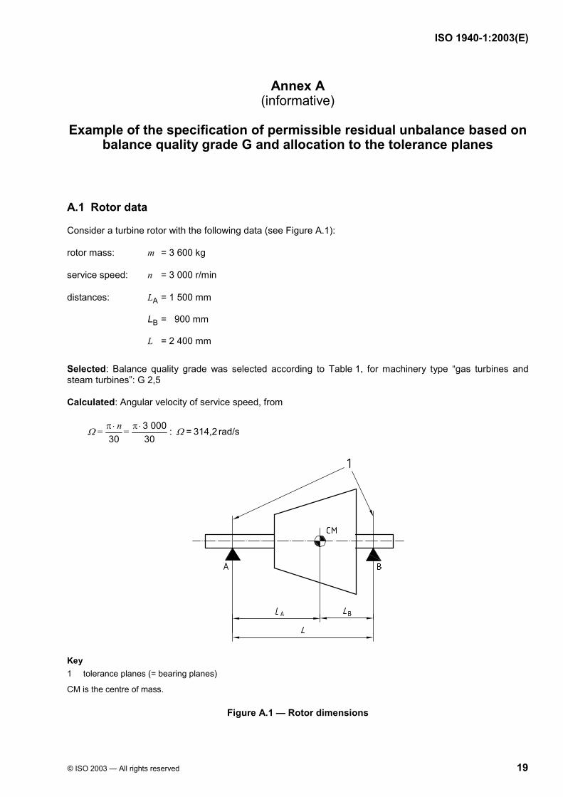
Consider a turbine rotor with the following data (see Figure A.1):
rotor mass: m = 3 600 kg
service speed: n = 3 000 r/min
distances: LA = 1 500 mm
LB = 900 mm
L = 2 400 mm
Selected: Balance quality grade was selected according to Table 1, for machinery type “gas turbines and steam turbines”: G 2,5
Calculated: Angular velocity of service speed, from
3 00030 30
n = = Ω π ⋅ π ⋅ : rad/s314,2 = Ω
Key 1 tolerance planes (= bearing planes)
CM is the centre of mass.
Figure A.1 — Rotor dimensions
ISO 1940-1:2003(E)
20 © ISO 2003 — All rights reserved
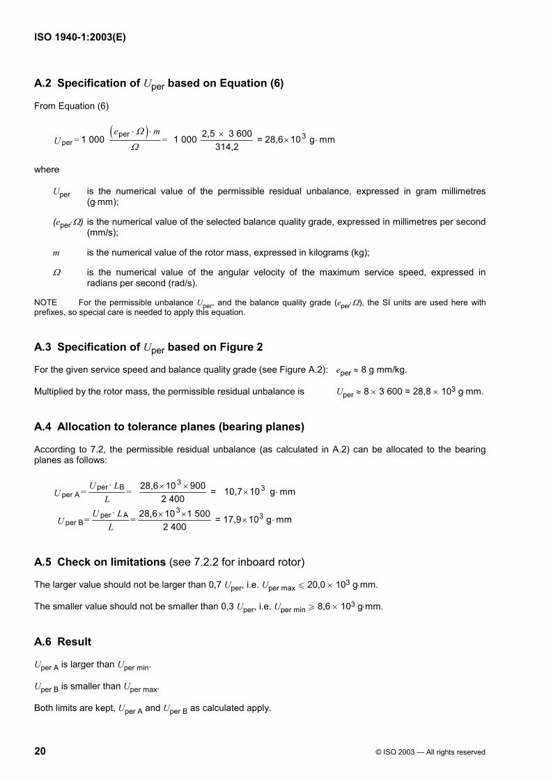
A.2 Specification of Uper based on Equation (6)
From Equation (6)
( )per 3per
2,5 3 6001 000 1 000 = 28,6 10 g mm314,2
e m = =U
Ω
Ω
⋅ ⋅ ×× ⋅
where
Uper is the numerical value of the permissible residual unbalance, expressed in gram millimetres (g⋅mm);
(eper⋅Ω) is the numerical value of the selected balance quality grade, expressed in millimetres per second (mm/s);
m is the numerical value of the rotor mass, expressed in kilograms (kg);
Ω is the numerical value of the angular velocity of the maximum service speed, expressed in radians per second (rad/s).
NOTE For the permissible unbalance Uper, and the balance quality grade (eper⋅Ω), the SI units are used here with prefixes, so special care is needed to apply this equation.
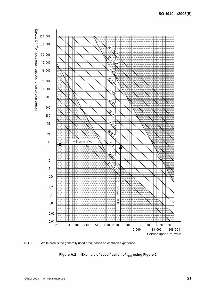
A.3 Specification of Uper based on Figure 2
For the given service speed and balance quality grade (see Figure A.2): eper ≈ 8 g mm/kg.
Multiplied by the rotor mass, the permissible residual unbalance is Uper ≈ 8 × 3 600 = 28,8 × 10³ g⋅mm.
A.4 Allocation to tolerance planes (bearing planes)
According to 7.2, the permissible residual unbalance (as calculated in A.2) can be allocated to the bearing planes as follows:
3Bper 3per A
3Aper 3per B
28,6 10 900 = 10,7 10 g mm2 400
28,6 10 1 500 = 17,9 10 g mm2 400
U L = =U L
U L = = U L
⋅ × ×× ⋅
⋅ × ×× ⋅
A.5 Check on limitations (see 7.2.2 for inboard rotor)
The larger value should not be larger than 0,7 Uper, i.e. Uper max u 20,0 × 10³ g⋅mm.
The smaller value should not be smaller than 0,3 Uper, i.e. Uper min W 8,6 × 10³ g⋅mm.
A.6 Result
Uper A is larger than Uper min.
Uper B is smaller than Uper max.
Both limits are kept, Uper A and Uper B as calculated apply.
ISO 1940-1:2003(E)
© ISO 2003 — All rights reserved 21
NOTE White area is the generally used area, based on common experience.
Figure A.2 — Example of specification of eper using Figure 2
ISO 1940-1:2003(E)
22 © ISO 2003 — All rights reserved
Annex B (informative)
Specification of balance tolerances based on bearing force limits
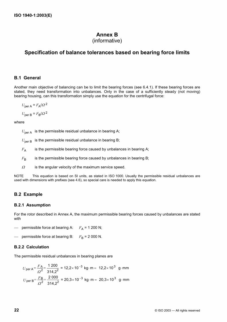
B.1 General
Another main objective of balancing can be to limit the bearing forces (see 6.4.1). If these bearing forces are stated, they need transformation into unbalances. Only in the case of a sufficiently steady (not moving) bearing housing, can this transformation simply use the equation for the centrifugal force:
Uper A = FA/Ω 2
Uper B = FB/Ω 2
where
Uper A is the permissible residual unbalance in bearing A;
Uper B is the permissible residual unbalance in bearing B;
FA is the permissible bearing force caused by unbalances in bearing A;
FB is the permissible bearing force caused by unbalances in bearing B;
Ω is the angular velocity of the maximum service speed.
NOTE This equation is based on SI units, as stated in ISO 1000. Usually the permissible residual unbalances are used with dimensions with prefixes (see 4.6), so special care is needed to apply this equation.
B.2 Example
B.2.1 Assumption
For the rotor described in Annex A, the maximum permissible bearing forces caused by unbalances are stated with
permissible force at bearing A: FA = 1 200 N;
permissible force at bearing B: FB = 2 000 N.
B.2.2 Calculation
The permissible residual unbalances in bearing planes are
3 3Aper A 2 2
3 3Bper B 2 2
1 200 = 12,2 10 kg m 12,2 10 g mm314,22 000 = 20,3 10 kg m 20,3 10 g mm314,2
F = = U
F = = U
Ω
Ω
−
−
× ⋅ = × ⋅
× ⋅ = × ⋅
ISO 1940-1:2003(E)
© ISO 2003 — All rights reserved 23
Annex C (informative)
Specification of balance tolerances based on vibration limits
Elaborated models and calculations are often used to investigate the dynamic behaviour of rotors or complete machines and to check their vibrational response to unbalances. Such an approach is much too extensive and cannot be handled in this part of ISO 1940.
A simplified method seems to be applicable in easy cases, but a proven basis is not yet available.
ISO 1940-1:2003(E)
24 © ISO 2003 — All rights reserved
Annex D (informative)
Specification of balance tolerances based on established experience
D.1 General
If a company has gained sufficient documented experience to assess the balance quality of its products, it may make full use of this. Assuming the general aim is still the same, then the new balance tolerance can be based on experience with the other rotors.
D.2 Almost identical rotor size
For a new rotor size, almost identical to others that have been successfully balanced, identical balance tolerances apply.
Use the same limits in similarly located tolerance planes.
D.3 Similar rotor size
D.3.1 General
For a new rotor size, similar to others that have been successfully balanced, balance tolerances may be derived in different ways, as given in D.3.2 and D.3.3.
D.3.2 Interpolation
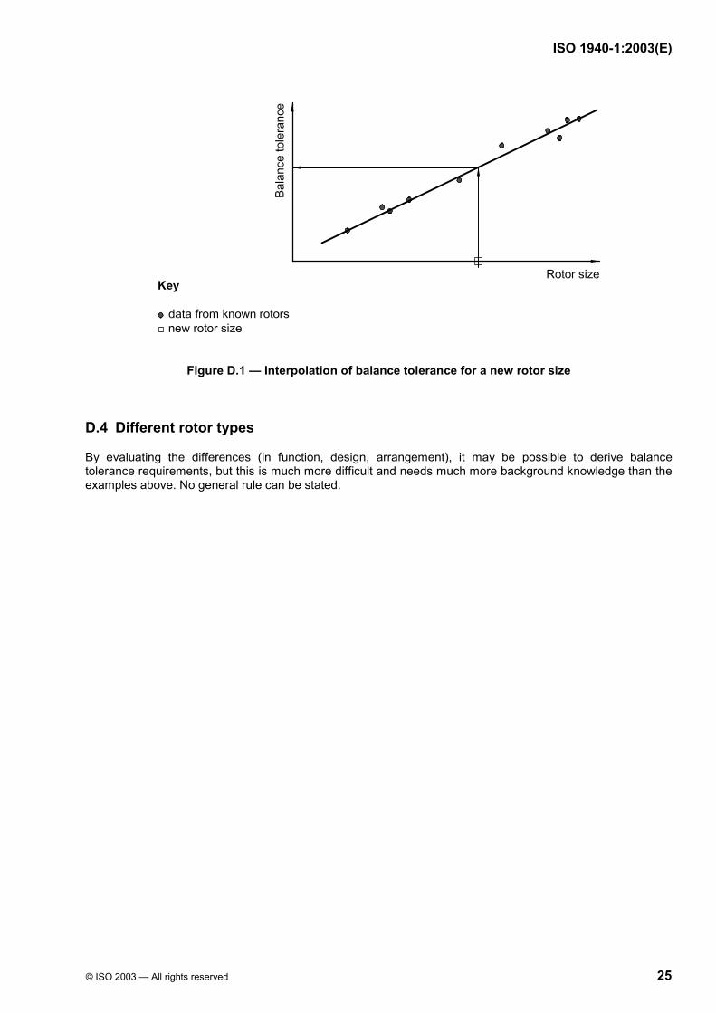
A graph shows the dependence of the balance tolerance on the rotor size (diameter, mass, power) for known rotors. The necessary balance tolerance for a new rotor size can be derived from such a graph (see Figure D.1).
NOTE For different types of rotors, different graphs may be needed.
Use adjusted limits in similarly located tolerance planes.
D.3.3 Calculation
For a range of rotors of the same type, rules of similarity apply for the rotor mass and rotor speed, as described in Clause 5. The permissible residual unbalance Uper is proportional to the rotor mass m and inversely proportional to the service speed n.
To calculate the permissible residual unbalance for a new rotor size on the basis of a known one, the following equation may be used:
new knownper new per known
known new
m n = U Um n
⋅
If permissible residual unbalances for the tolerance planes are known, similar equations may be used to calculate the values for a new rotor size.
Use recalculated limits in similarly located tolerance planes.
ISO 1940-1:2003(E)
© ISO 2003 — All rights reserved 25
Figure D.1 — Interpolation of balance tolerance for a new rotor size
D.4 Different rotor types
By evaluating the differences (in function, design, arrangement), it may be possible to derive balance tolerance requirements, but this is much more difficult and needs much more background knowledge than the examples above. No general rule can be stated.
ISO 1940-1:2003(E)
26 © ISO 2003 — All rights reserved
Annex E (informative)
Rules for allocating balance tolerances from tolerance planes
to correction planes
E.1 General
As explained in 4.4 and 8.1, it is recommended to use the tolerance planes (often identical to the bearing planes) and not the correction planes to state balance tolerances. But for the case where the balancing process still needs balance tolerances in the correction planes, Clauses E.2 to E.4 give some basic rules.
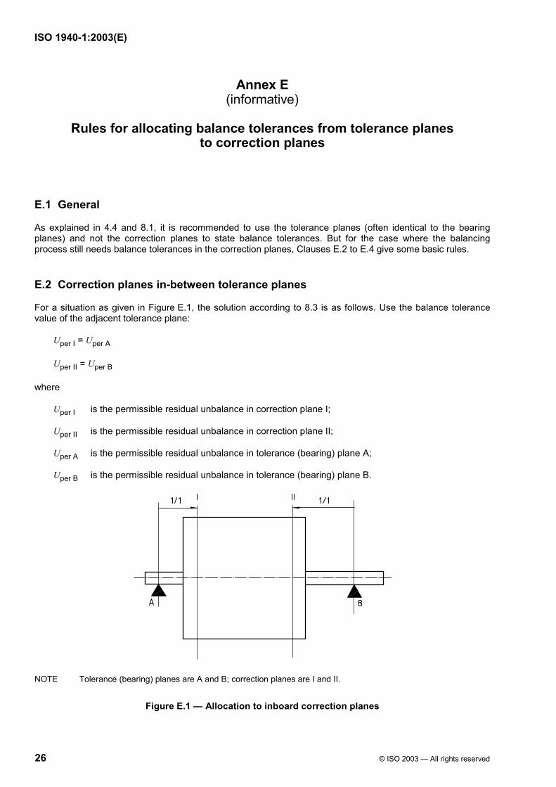
E.2 Correction planes in-between tolerance planes
For a situation as given in Figure E.1, the solution according to 8.3 is as follows. Use the balance tolerance value of the adjacent tolerance plane:
Uper I = Uper A
Uper II = Uper B
where
Uper I is the permissible residual unbalance in correction plane I;
Uper II is the permissible residual unbalance in correction plane II;
Uper A is the permissible residual unbalance in tolerance (bearing) plane A;
Uper B is the permissible residual unbalance in tolerance (bearing) plane B.
NOTE Tolerance (bearing) planes are A and B; correction planes are I and II.
Figure E.1 — Allocation to inboard correction planes
ISO 1940-1:2003(E)
© ISO 2003 — All rights reserved 27
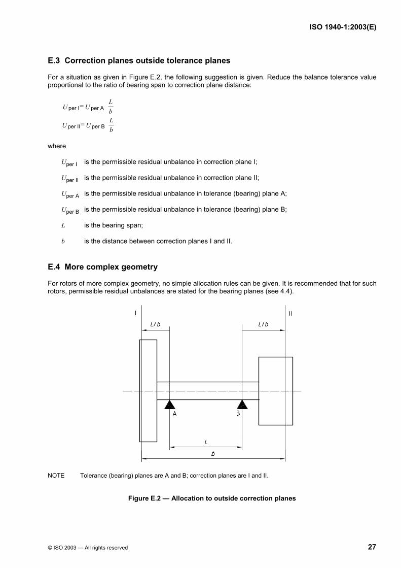
E.3 Correction planes outside tolerance planes
For a situation as given in Figure E.2, the following suggestion is given. Reduce the balance tolerance value proportional to the ratio of bearing span to correction plane distance:
per I per A
per II per B
L = U U bL = U U b
where
Uper I is the permissible residual unbalance in correction plane I;
Uper II is the permissible residual unbalance in correction plane II;
Uper A is the permissible residual unbalance in tolerance (bearing) plane A;
Uper B is the permissible residual unbalance in tolerance (bearing) plane B;
L is the bearing span;
b is the distance between correction planes I and II.
E.4 More complex geometry
For rotors of more complex geometry, no simple allocation rules can be given. It is recommended that for such rotors, permissible residual unbalances are stated for the bearing planes (see 4.4).
NOTE Tolerance (bearing) planes are A and B; correction planes are I and II.
Figure E.2 — Allocation to outside correction planes
ISO 1940-1:2003(E)
28 © ISO 2003 — All rights reserved
Bibliography
[1] ISO 1000, SI units and recommendations for the use of their multiples and of certain other units
[2] ISO 2041, Vibration and shock — Vocabulary
[3] ISO 2953, Mechanical vibration — Balancing machines — Description and evaluation
[4] ISO 8821, Mechanical vibration — Balancing — Shaft and fitment key convention
[5] ISO 11342, Mechanical vibration — Methods and criteria for the mechanical balancing of flexible rotors
[6] ISO 14694, Industrial fans — Specifications for balance quality and vibration levels

ISO 1940-1:2003(E)
ICS 21.120.40 Price based on 28 pages
© ISO 2003 — All rights reserved