Embed Size (px)
Citation preview
1
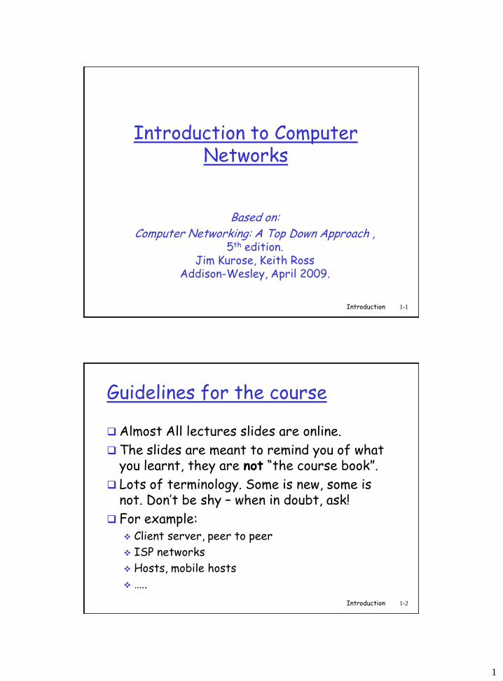
Introduction to Computer Networks
Based on:
Computer Networking: A Top Down Approach ,5th edition.
Jim Kurose, Keith RossAddison-Wesley, April 2009.
Introduction 1-1
Guidelines for the course
Almost All lectures slides are online.
The slides are meant to remind you of what you learnt, they are not “the course book”.
Lots of terminology. Some is new, some is not. Don’t be shy – when in doubt, ask!
For example: Client server, peer to peer
ISP networks
Hosts, mobile hosts
…..
Introduction 1-2
2
Introduction 1-3
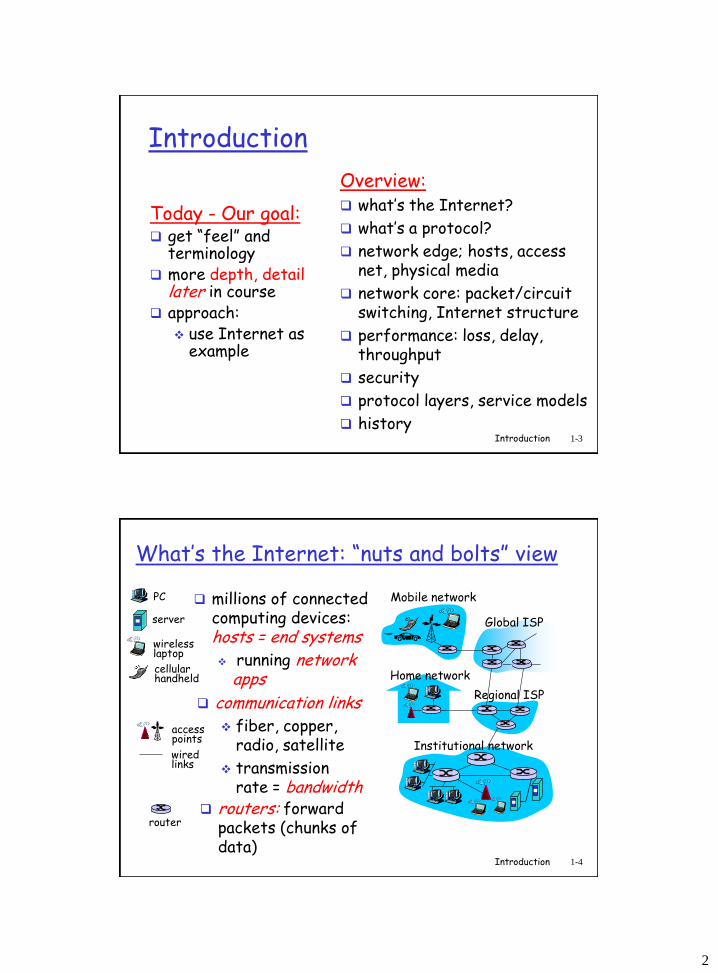
Introduction
Today - Our goal: get “feel” and
terminology more depth, detail
later in course approach:
use Internet as example
Overview: what’s the Internet?
what’s a protocol?
network edge; hosts, access net, physical media
network core: packet/circuit switching, Internet structure
performance: loss, delay, throughput
security
protocol layers, service models
history
Introduction 1-4
What’s the Internet: “nuts and bolts” view
millions of connected computing devices: hosts = end systems
running network apps Home network
Institutional network
Mobile network
Global ISP
Regional ISP
router
PC
server
wirelesslaptop
cellular handheld
wiredlinks
access points
communication links
fiber, copper, radio, satellite
transmission rate = bandwidth
routers: forward packets (chunks of data)
3
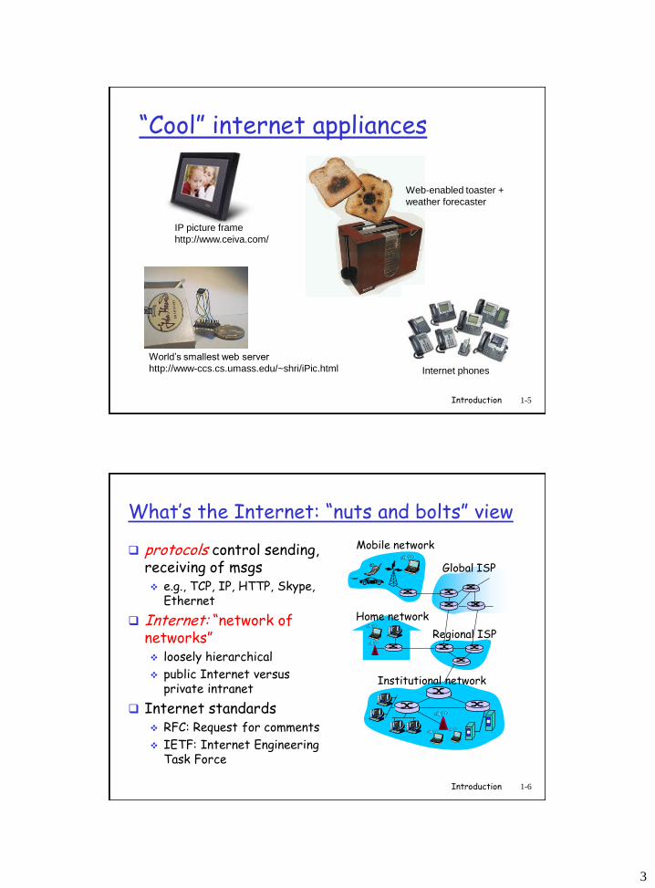
Introduction 1-5
“Cool” internet appliances
World’s smallest web server
http://www-ccs.cs.umass.edu/~shri/iPic.html
IP picture frame
http://www.ceiva.com/
Web-enabled toaster +
weather forecaster
Internet phones
Introduction 1-6
What’s the Internet: “nuts and bolts” view
protocols control sending, receiving of msgs e.g., TCP, IP, HTTP, Skype,
Ethernet
Internet: “network of networks” loosely hierarchical
public Internet versus private intranet
Internet standards RFC: Request for comments
IETF: Internet Engineering Task Force
Home network
Institutional network
Mobile network
Global ISP
Regional ISP
4
Introduction 1-7
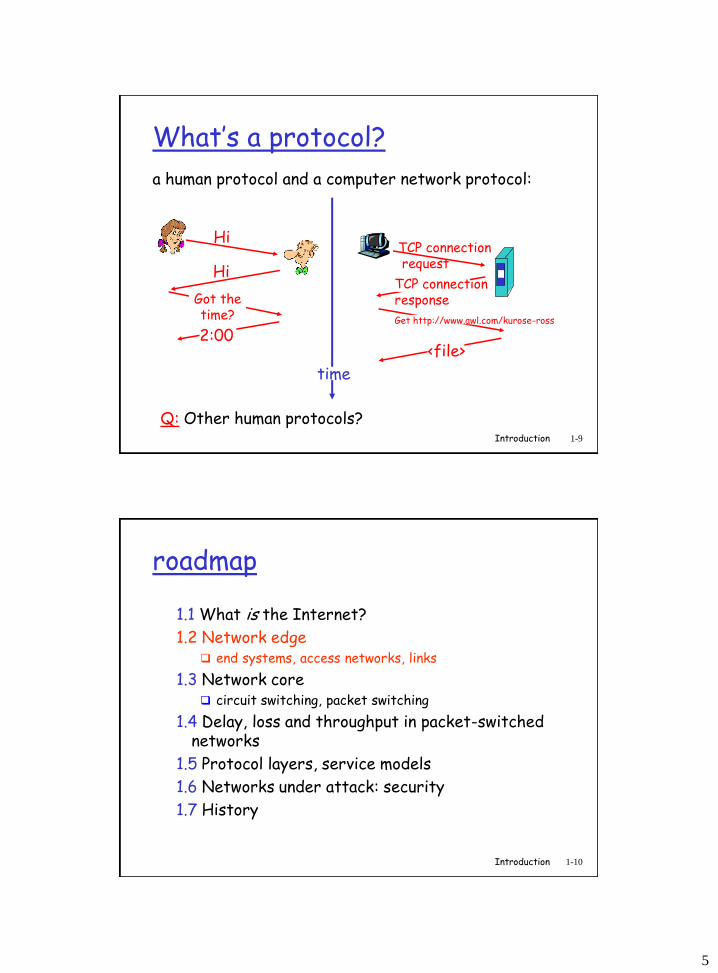
What’s the Internet: a service view
communication infrastructure enables distributed applications:
Web, VoIP, email, games, e-commerce, file sharing
communication services provided to apps:
reliable data delivery from source to destination
“best effort” (unreliable) data delivery
Introduction 1-8
What’s a protocol?
human protocols:
“what’s the time?”
“I have a question”
introductions
… specific msgs sent
… specific actions taken when msgs received, or other events
network protocols:
machines rather than humans
all communication activity in Internet governed by protocols
protocols define format, order of msgs sent and received among network
entities, and actions taken on msg
transmission, receipt
5
Introduction 1-9
What’s a protocol?
a human protocol and a computer network protocol:
Q: Other human protocols?
Hi
Hi
Got thetime?
2:00
TCP connectionrequest
TCP connectionresponse
Get http://www.awl.com/kurose-ross
<file>
time
Introduction 1-10
roadmap
1.1 What is the Internet?
1.2 Network edge end systems, access networks, links
1.3 Network core circuit switching, packet switching
1.4 Delay, loss and throughput in packet-switched networks
1.5 Protocol layers, service models
1.6 Networks under attack: security
1.7 History
6
Introduction 1-11
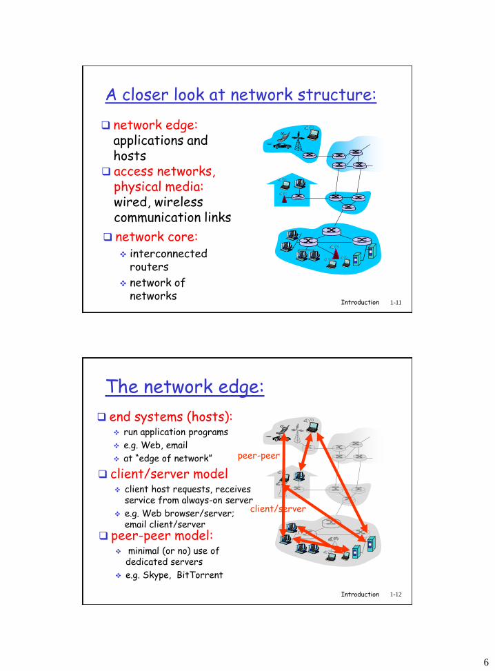
A closer look at network structure:
network edge:applications and hosts
access networks, physical media:wired, wireless communication links
network core: interconnected
routers
network of networks
Introduction 1-12
The network edge:
end systems (hosts): run application programs
e.g. Web, email
at “edge of network”
client/server
peer-peer
client/server model client host requests, receives
service from always-on server
e.g. Web browser/server; email client/server
peer-peer model: minimal (or no) use of
dedicated servers
e.g. Skype, BitTorrent
7
Introduction 1-13
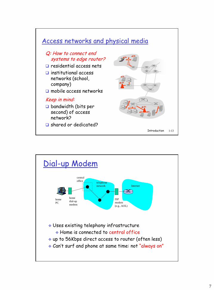
Access networks and physical media
Q: How to connect end systems to edge router?
residential access nets
institutional access networks (school, company)
mobile access networks
Keep in mind: bandwidth (bits per
second) of access network?
shared or dedicated?
telephone
network Internet
home
dial-up
modem
ISP
modem
(e.g., AOL)
home
PC
central
office
Uses existing telephony infrastructure
Home is connected to central office
up to 56Kbps direct access to router (often less)
Can’t surf and phone at same time: not “always on”
Dial-up Modem
8
telephone
network
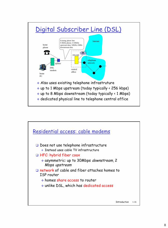
DSL
modem
home
PC
home
phone
Internet
DSLAM
Existing phone line:
0-4KHz phone; 4-50KHz
upstream data; 50KHz-1MHz
downstream data
splitter
central
office
Digital Subscriber Line (DSL)
Also uses existing telephone infrastruture
up to 1 Mbps upstream (today typically < 256 kbps)
up to 8 Mbps downstream (today typically < 1 Mbps)
dedicated physical line to telephone central office
Introduction 1-16
Residential access: cable modems
Does not use telephone infrastructure Instead uses cable TV infrastructure
HFC: hybrid fiber coax
asymmetric: up to 30Mbps downstream, 2 Mbps upstream
network of cable and fiber attaches homes to ISP router
homes share access to router
unlike DSL, which has dedicated access
9
Introduction 1-17
Cable Network Architecture: Overview
home
cable headend
cable distribution
network (simplified)
Typically 500 to 5,000 homes
Introduction 1-18
Cable Network Architecture: Overview
home
cable headend
cable distribution
network
server(s)
10
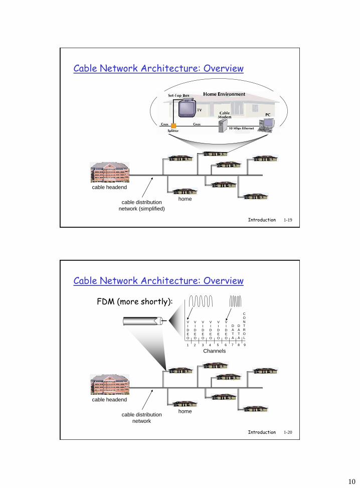
Introduction 1-19
Cable Network Architecture: Overview
home
cable headend
cable distribution
network (simplified)
Introduction 1-20
Cable Network Architecture: Overview
home
cable headend
cable distribution
network
Channels
V
I
D
E
O
V
I
D
E
O
V
I
D
E
O
V
I
D
E
O
V
I
D
E
O
V
I
D
E
O
D
A
T
A
D
A
T
A
C
O
N
T
R
O
L
1 2 3 4 5 6 7 8 9
FDM (more shortly):
11
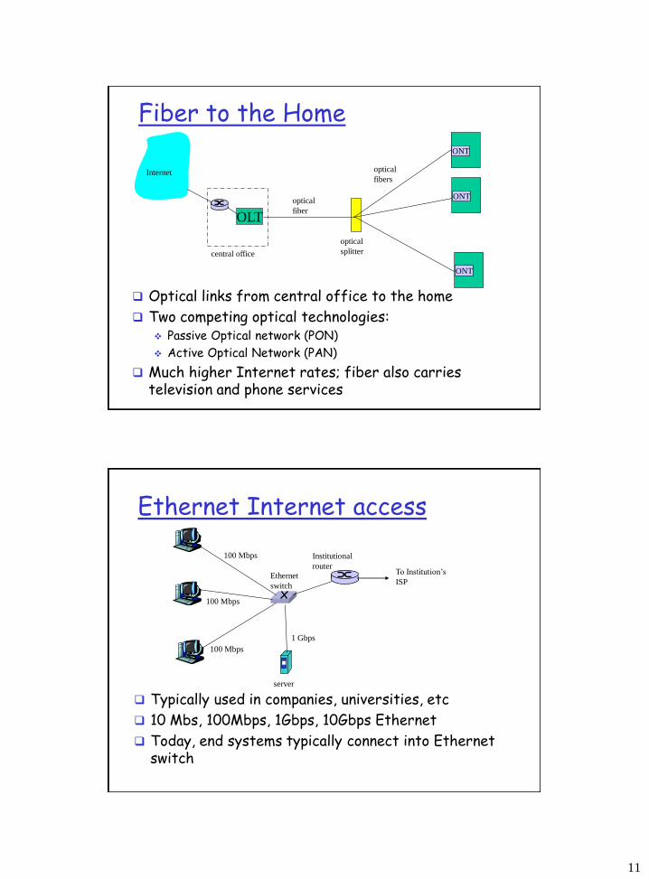
ONT
OLT
central office
optical
splitter
ONT
ONT
optical
fiber
optical
fibersInternet
Fiber to the Home
Optical links from central office to the home
Two competing optical technologies: Passive Optical network (PON)
Active Optical Network (PAN)
Much higher Internet rates; fiber also carries television and phone services
100 Mbps
100 Mbps
100 Mbps
1 Gbps
server
Ethernet
switch
Institutional
routerTo Institution’s
ISP
Ethernet Internet access
Typically used in companies, universities, etc
10 Mbs, 100Mbps, 1Gbps, 10Gbps Ethernet
Today, end systems typically connect into Ethernet switch
12
Introduction 1-23
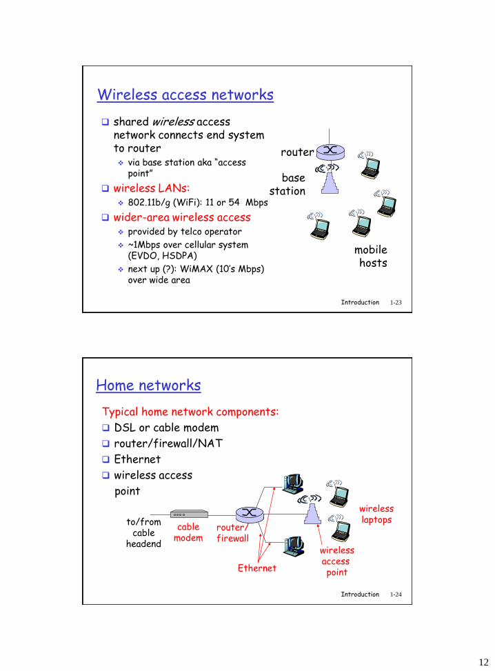
Wireless access networks
shared wireless access network connects end system to router via base station aka “access
point”
wireless LANs: 802.11b/g (WiFi): 11 or 54 Mbps
wider-area wireless access provided by telco operator
~1Mbps over cellular system (EVDO, HSDPA)
next up (?): WiMAX (10’s Mbps) over wide area
basestation
mobilehosts
router
Introduction 1-24
Home networks
Typical home network components:
DSL or cable modem
router/firewall/NAT
Ethernet
wireless access
point
wirelessaccess point
wirelesslaptops
router/firewall
cablemodem
to/fromcable
headend
Ethernet
13
Introduction 1-25
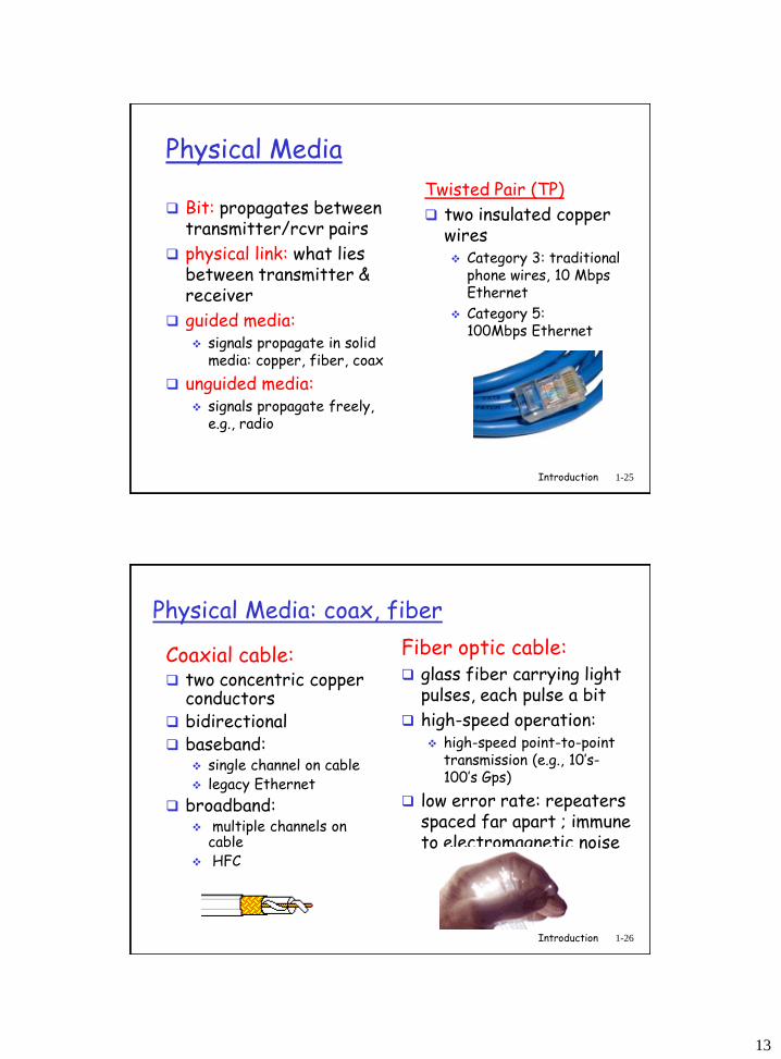
Physical Media
Bit: propagates betweentransmitter/rcvr pairs
physical link: what lies between transmitter & receiver
guided media: signals propagate in solid
media: copper, fiber, coax
unguided media: signals propagate freely,
e.g., radio
Twisted Pair (TP)
two insulated copper wires Category 3: traditional
phone wires, 10 Mbps Ethernet
Category 5: 100Mbps Ethernet
Introduction 1-26
Physical Media: coax, fiber
Coaxial cable: two concentric copper
conductors bidirectional baseband:
single channel on cable legacy Ethernet
broadband: multiple channels on
cable HFC
Fiber optic cable: glass fiber carrying light
pulses, each pulse a bit
high-speed operation: high-speed point-to-point
transmission (e.g., 10’s-100’s Gps)
low error rate: repeaters spaced far apart ; immune to electromagnetic noise
14
Introduction 1-27
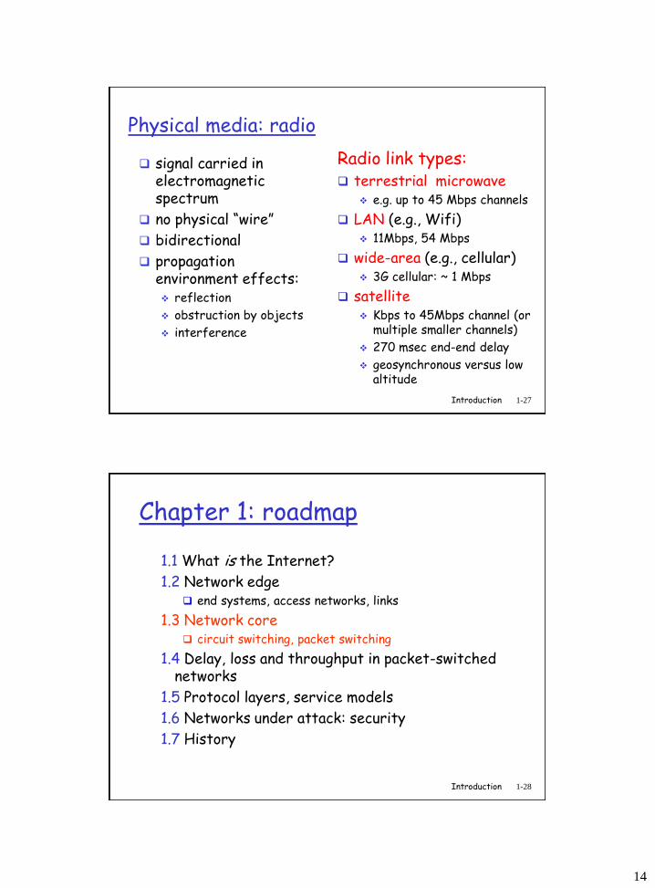
Physical media: radio
signal carried in electromagnetic spectrum
no physical “wire”
bidirectional
propagation environment effects: reflection
obstruction by objects
interference
Radio link types: terrestrial microwave
e.g. up to 45 Mbps channels
LAN (e.g., Wifi) 11Mbps, 54 Mbps
wide-area (e.g., cellular) 3G cellular: ~ 1 Mbps
satellite Kbps to 45Mbps channel (or
multiple smaller channels)
270 msec end-end delay
geosynchronous versus low altitude
Introduction 1-28
Chapter 1: roadmap
1.1 What is the Internet?
1.2 Network edge end systems, access networks, links
1.3 Network core circuit switching, packet switching
1.4 Delay, loss and throughput in packet-switched networks
1.5 Protocol layers, service models
1.6 Networks under attack: security
1.7 History
15
Introduction 1-29
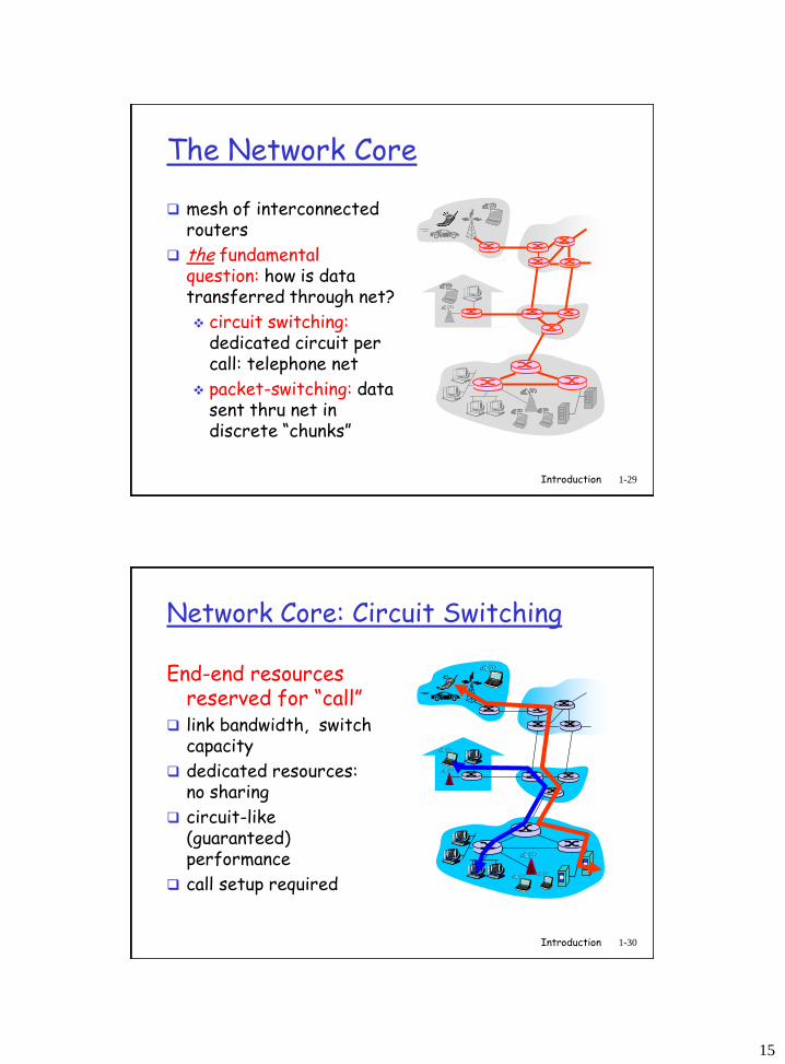
The Network Core
mesh of interconnected routers
the fundamental question: how is data transferred through net?
circuit switching:dedicated circuit per call: telephone net
packet-switching: data sent thru net in discrete “chunks”
Introduction 1-30
Network Core: Circuit Switching
End-end resources reserved for “call”
link bandwidth, switch capacity
dedicated resources: no sharing
circuit-like (guaranteed) performance
call setup required
16
Introduction 1-31
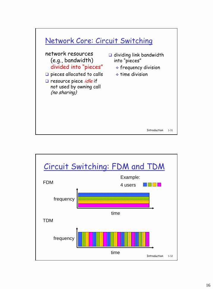
Network Core: Circuit Switching
network resources (e.g., bandwidth) divided into “pieces”
pieces allocated to calls
resource piece idle if not used by owning call (no sharing)
dividing link bandwidth into “pieces”
frequency division
time division
Introduction 1-32
Circuit Switching: FDM and TDM
FDM
frequency
time
TDM
frequency
time
4 users
Example:
17
Introduction 1-33
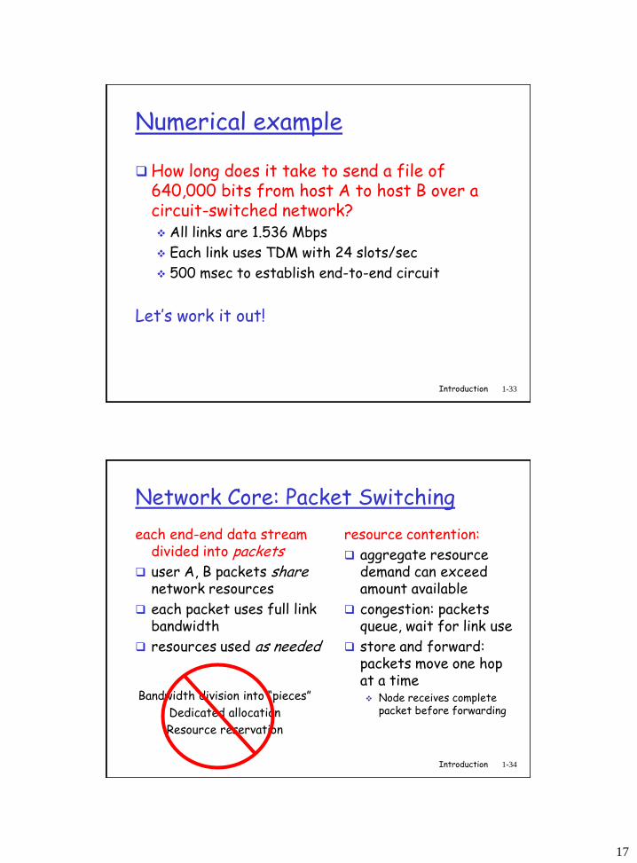
Numerical example
How long does it take to send a file of 640,000 bits from host A to host B over a circuit-switched network? All links are 1.536 Mbps
Each link uses TDM with 24 slots/sec
500 msec to establish end-to-end circuit
Let’s work it out!
Introduction 1-34
Network Core: Packet Switching
each end-end data stream divided into packets
user A, B packets sharenetwork resources
each packet uses full link bandwidth
resources used as needed
resource contention:
aggregate resource demand can exceed amount available
congestion: packets queue, wait for link use
store and forward: packets move one hop at a time Node receives complete
packet before forwardingBandwidth division into “pieces”
Dedicated allocation
Resource reservation
18
Introduction 1-35
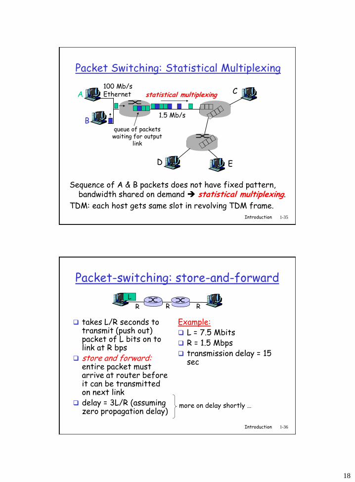
Packet Switching: Statistical Multiplexing
Sequence of A & B packets does not have fixed pattern, bandwidth shared on demand statistical multiplexing.
TDM: each host gets same slot in revolving TDM frame.
A
B
C100 Mb/sEthernet
1.5 Mb/s
D E
statistical multiplexing
queue of packetswaiting for output
link
Introduction 1-36
Packet-switching: store-and-forward
takes L/R seconds to transmit (push out) packet of L bits on to link at R bps
store and forward: entire packet must arrive at router before it can be transmitted on next link
delay = 3L/R (assuming zero propagation delay)
Example: L = 7.5 Mbits R = 1.5 Mbps transmission delay = 15
sec
R R R
L
more on delay shortly …
19
Introduction 1-37
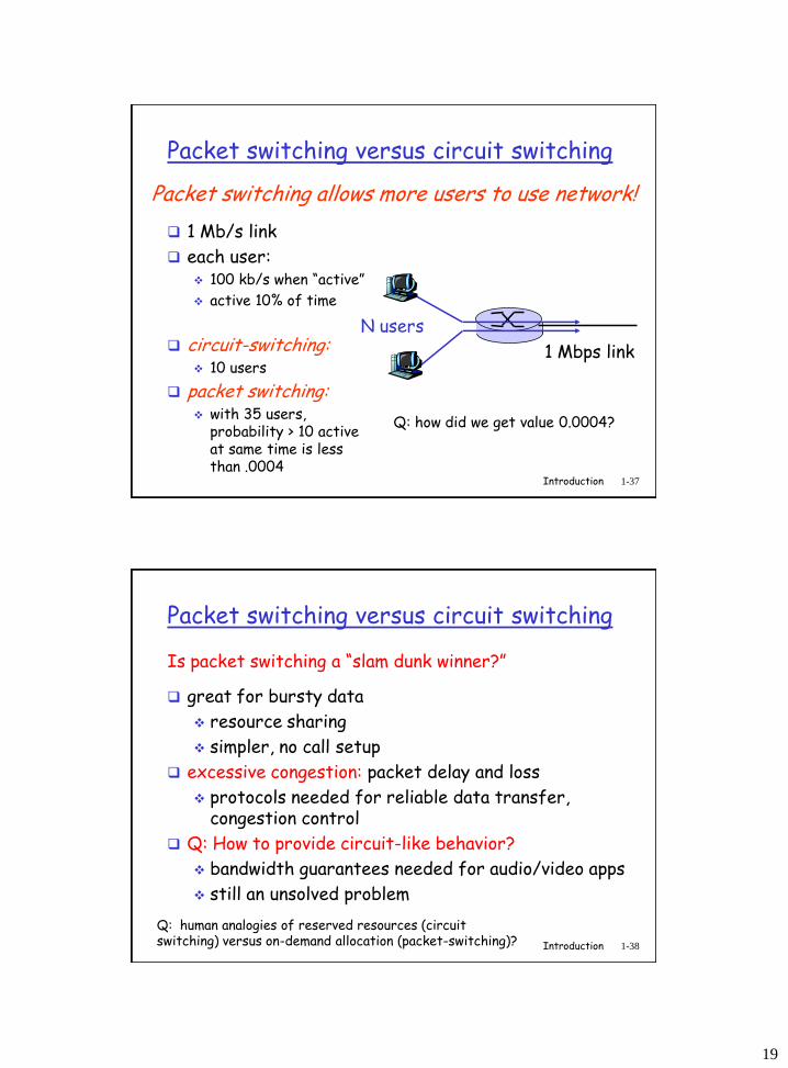
Packet switching versus circuit switching
1 Mb/s link
each user: 100 kb/s when “active”
active 10% of time
circuit-switching: 10 users
packet switching: with 35 users,
probability > 10 active at same time is less than .0004
Packet switching allows more users to use network!
N users
1 Mbps link
Q: how did we get value 0.0004?
Introduction 1-38
Packet switching versus circuit switching
great for bursty data
resource sharing
simpler, no call setup
excessive congestion: packet delay and loss
protocols needed for reliable data transfer, congestion control
Q: How to provide circuit-like behavior?
bandwidth guarantees needed for audio/video apps
still an unsolved problem
Is packet switching a “slam dunk winner?”
Q: human analogies of reserved resources (circuit switching) versus on-demand allocation (packet-switching)?
20
Introduction 1-39
Chapter 1: roadmap
1.1 What is the Internet?
1.2 Network edge end systems, access networks, links
1.3 Network core circuit switching, packet switching
1.4 Delay, loss and throughput in packet-switched networks
1.5 Protocol layers, service models
1.6 Networks under attack: security
1.7 History
Introduction 1-40
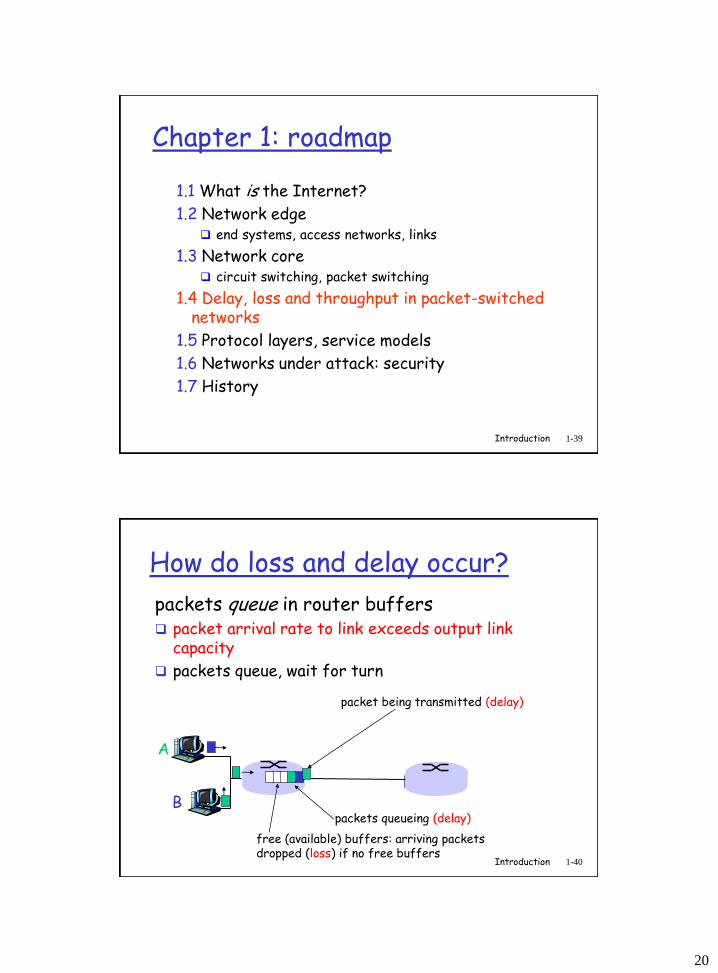
How do loss and delay occur?
packets queue in router buffers packet arrival rate to link exceeds output link
capacity
packets queue, wait for turn
A
B
packet being transmitted (delay)
packets queueing (delay)
free (available) buffers: arriving packets dropped (loss) if no free buffers
21
Introduction 1-41
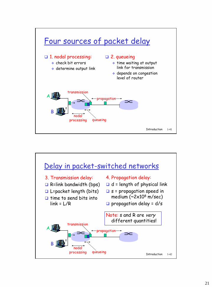
Four sources of packet delay
1. nodal processing: check bit errors
determine output link
A
B
propagation
transmission
nodalprocessing queueing
2. queueing time waiting at output
link for transmission
depends on congestion level of router
Introduction 1-42
Delay in packet-switched networks
3. Transmission delay:
R=link bandwidth (bps)
L=packet length (bits)
time to send bits into link = L/R
4. Propagation delay:
d = length of physical link
s = propagation speed in medium (~2x10⁸ m/sec)
propagation delay = d/s
A
B
propagation
transmission
nodalprocessing queueing
Note: s and R are very different quantities!
22
Transmission vs. Prop. Delay
pipe
1. Propagation delay is how long takes to cross the pipe, irrespective of volume
2. Transmission (bandwidth delay) is related to how
much water can be pushed in through the opening
per unit time
43Mokryn, Binsky
Introduction 1-44
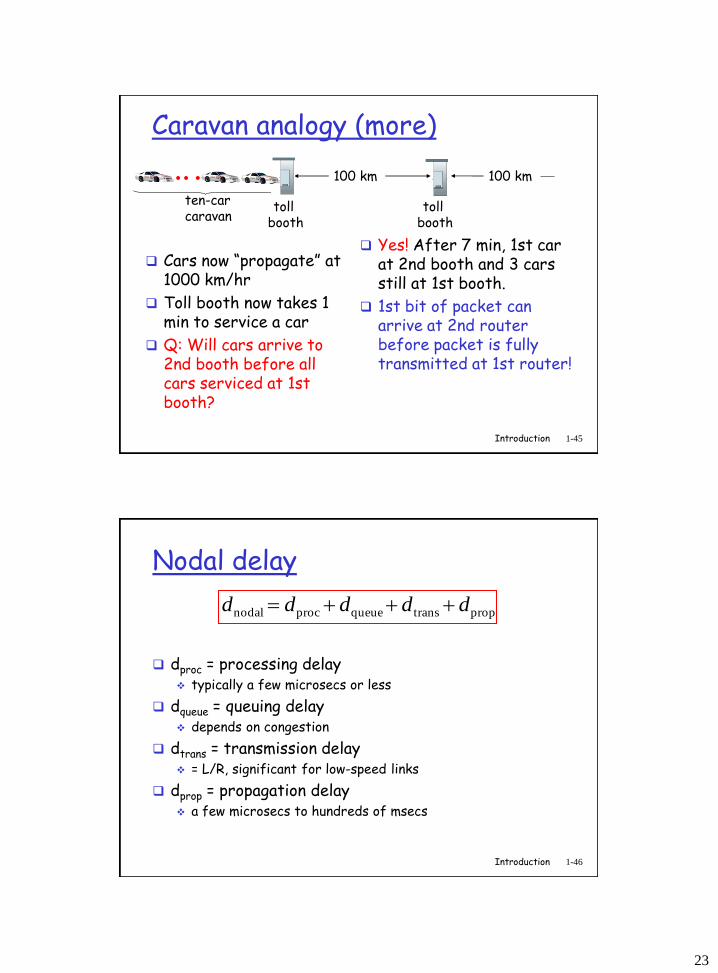
Caravan analogy
cars “propagate” at 100 km/hr
toll booth takes 12 sec to service car (transmission time)
car~bit; caravan ~ packet
Q: How long until caravan is lined up before 2nd toll booth?
Time to “push” entire caravan through toll booth onto highway = 12*10 = 120 sec
Time for last car to propagate from 1st to 2nd toll both: 100km/(100km/hr)= 1 hr
A: 62 minutes
toll booth
toll booth
ten-car caravan
100 km 100 km
23
Introduction 1-45
Caravan analogy (more)
Cars now “propagate” at 1000 km/hr
Toll booth now takes 1 min to service a car
Q: Will cars arrive to 2nd booth before all cars serviced at 1st booth?
Yes! After 7 min, 1st car at 2nd booth and 3 cars still at 1st booth.
1st bit of packet can arrive at 2nd router before packet is fully transmitted at 1st router!
toll booth
toll booth
ten-car caravan
100 km 100 km
Introduction 1-46
Nodal delay
dproc = processing delay typically a few microsecs or less
dqueue = queuing delay depends on congestion
dtrans = transmission delay = L/R, significant for low-speed links
dprop = propagation delay a few microsecs to hundreds of msecs
proptransqueueprocnodal ddddd
24
1500 x 8 bits
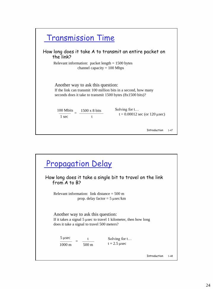
Transmission Time
How long does it take A to transmit an entire packet on the link?Relevant information: packet length = 1500 bytes
channel capacity = 100 Mbps
Another way to ask this question:If the link can transmit 100 million bits in a second, how many
seconds does it take to transmit 1500 bytes (8x1500 bits)?
100 Mbits
1 sec=
t
Solving for t…
t = 0.00012 sec (or 120 sec)
1-47Introduction
Propagation Delay
How long does it take a single bit to travel on the link from A to B?
Relevant information: link distance = 500 m
prop. delay factor = 5 sec/km
Another way to ask this question:If it takes a signal 5 sec to travel 1 kilometer, then how long
does it take a signal to travel 500 meters?
5 sec
1000 m=
500 m
t Solving for t…
t = 2.5 sec
1-48Introduction
25
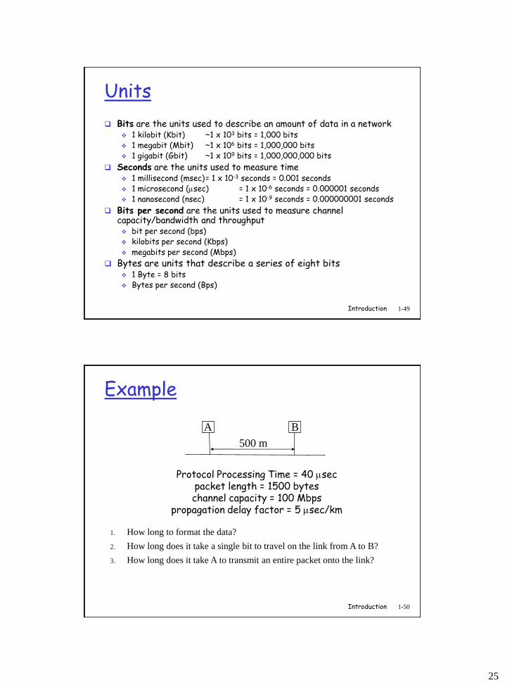
Units
Bits are the units used to describe an amount of data in a network 1 kilobit (Kbit) ~1 x 103 bits = 1,000 bits 1 megabit (Mbit) ~1 x 106 bits = 1,000,000 bits 1 gigabit (Gbit) ~1 x 109 bits = 1,000,000,000 bits
Seconds are the units used to measure time 1 millisecond (msec)= 1 x 10⁻³ seconds = 0.001 seconds 1 microsecond (sec) = 1 x 10⁻⁶ seconds = 0.000001 seconds 1 nanosecond (nsec) = 1 x 10⁻⁹ seconds = 0.000000001 seconds
Bits per second are the units used to measure channel capacity/bandwidth and throughput bit per second (bps) kilobits per second (Kbps) megabits per second (Mbps)
Bytes are units that describe a series of eight bits 1 Byte = 8 bits Bytes per second (Bps)
1-49Introduction
Example
Protocol Processing Time = 40 sec packet length = 1500 byteschannel capacity = 100 Mbps
propagation delay factor = 5 sec/km
A B
500 m
1. How long to format the data?
2. How long does it take a single bit to travel on the link from A to B?
3. How long does it take A to transmit an entire packet onto the link?
1-50Introduction
26
Timeline Method
Time
Protocol Delay
Transmission time
Propagation delay
Protocol Delay
Host A Host B
40
2.5
120
40
1st bit
last bit
Total time: 40+120+2.5+40 = 202.5 sec
1-51Introduction
Introduction 1-52
Packet loss
queue (aka buffer) preceding link in buffer has finite capacity
packet arriving to full queue dropped (aka lost)
lost packet may be retransmitted by previous node, by source end system, or not at all
A
B
packet being transmitted
packet arriving tofull buffer is lost
buffer (waiting area)
27
Introduction 1-53
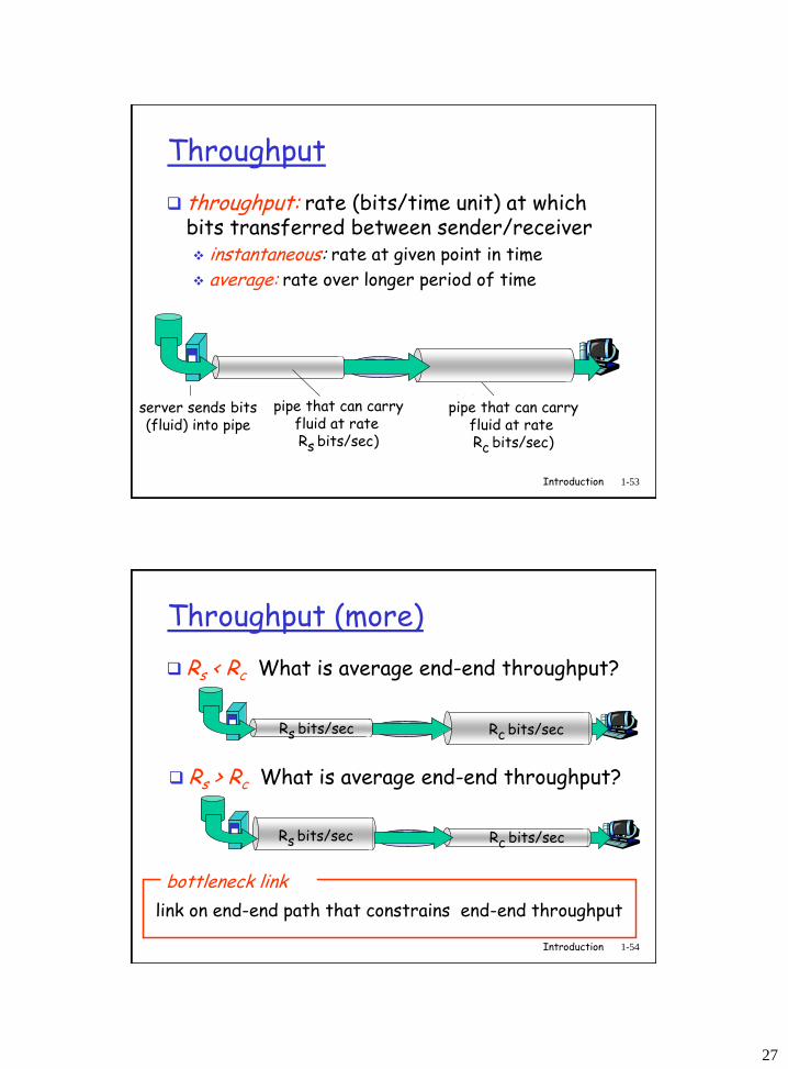
Throughput
throughput: rate (bits/time unit) at which bits transferred between sender/receiver instantaneous: rate at given point in time
average: rate over longer period of time
server, withfile of F bits
to send to client
link capacityRs bits/sec
link capacityRc bits/sec
pipe that can carryfluid at rateRs bits/sec)
pipe that can carryfluid at rateRc bits/sec)
server sends bits (fluid) into pipe
Introduction 1-54
Throughput (more)
Rs < Rc What is average end-end throughput?
Rs bits/sec Rc bits/sec
Rs > Rc What is average end-end throughput?
Rs bits/sec Rc bits/sec
link on end-end path that constrains end-end throughput
bottleneck link
28
Introduction 1-55
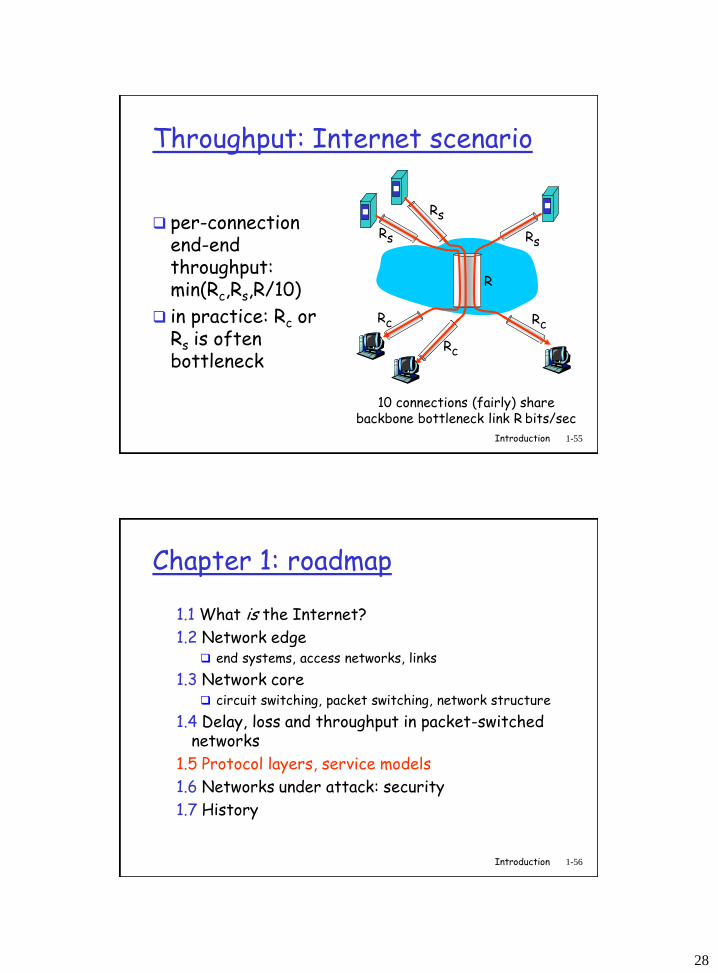
Throughput: Internet scenario
10 connections (fairly) share backbone bottleneck link R bits/sec
Rs
Rs
Rs
Rc
Rc
Rc
R
per-connection end-end throughput: min(Rc,Rs,R/10)
in practice: Rc or Rs is often bottleneck
Introduction 1-56
Chapter 1: roadmap
1.1 What is the Internet?
1.2 Network edge end systems, access networks, links
1.3 Network core circuit switching, packet switching, network structure
1.4 Delay, loss and throughput in packet-switched networks
1.5 Protocol layers, service models
1.6 Networks under attack: security
1.7 History
29
Introduction 1-57
Protocol “Layers”
Networks are complex!
many “pieces”:
hosts
routers
links of various media
applications
protocols
hardware, software
Question:Is there any hope of organizing structure of
network?
Or at least our discussion of networks?
Introduction 1-58
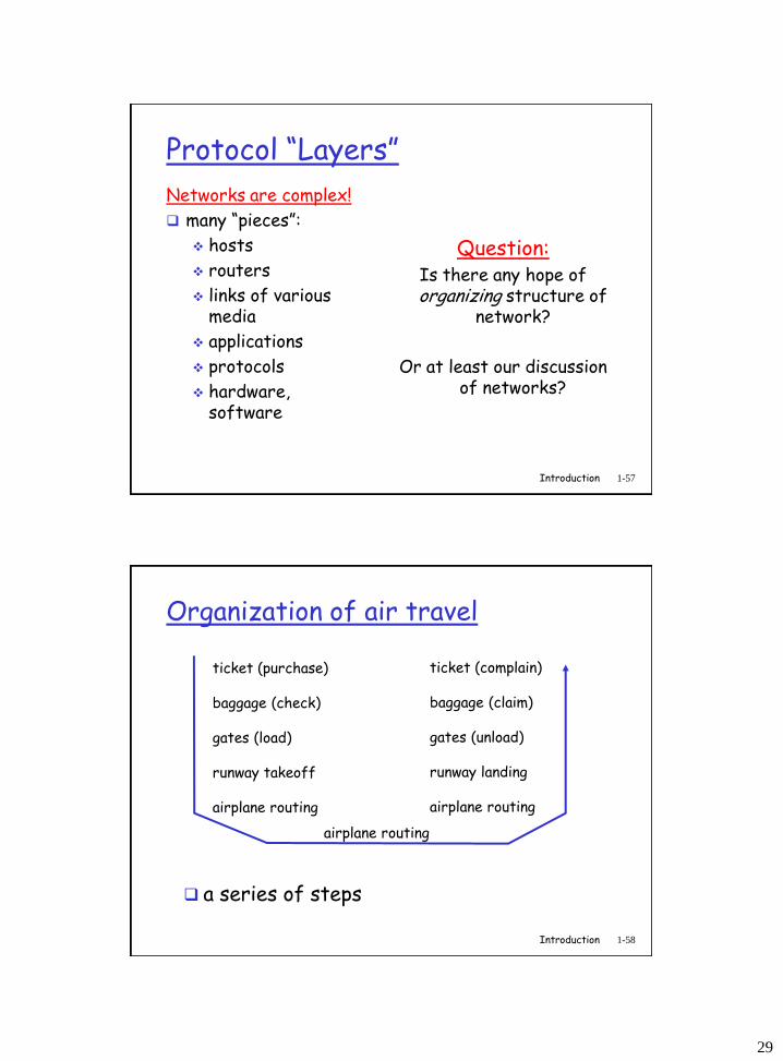
Organization of air travel
a series of steps
ticket (purchase)
baggage (check)
gates (load)
runway takeoff
airplane routing
ticket (complain)
baggage (claim)
gates (unload)
runway landing
airplane routing
airplane routing
30
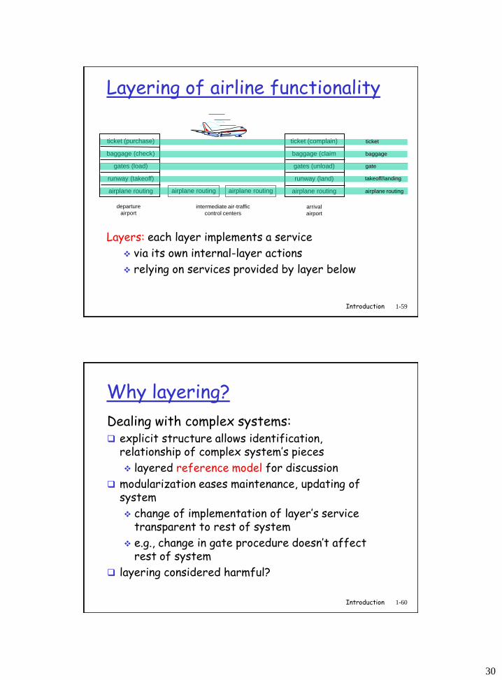
Introduction 1-59
ticket (purchase)
baggage (check)
gates (load)
runway (takeoff)
airplane routing
departure
airportarrival
airport
intermediate air-traffic
control centers
airplane routing airplane routing
ticket (complain)
baggage (claim
gates (unload)
runway (land)
airplane routing
ticket
baggage
gate
takeoff/landing
airplane routing
Layering of airline functionality
Layers: each layer implements a service
via its own internal-layer actions
relying on services provided by layer below
Introduction 1-60
Why layering?
Dealing with complex systems: explicit structure allows identification,
relationship of complex system’s pieces
layered reference model for discussion
modularization eases maintenance, updating of system
change of implementation of layer’s service transparent to rest of system
e.g., change in gate procedure doesn’t affect rest of system
layering considered harmful?
31
Introduction 1-61
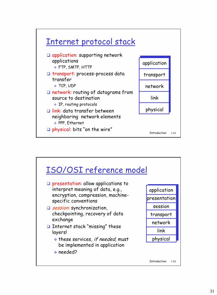
Internet protocol stack
application: supporting network applications FTP, SMTP, HTTP
transport: process-process data transfer TCP, UDP
network: routing of datagrams from source to destination IP, routing protocols
link: data transfer between neighboring network elements PPP, Ethernet
physical: bits “on the wire”
application
transport
network
link
physical
Introduction 1-62
ISO/OSI reference model
presentation: allow applications to interpret meaning of data, e.g., encryption, compression, machine-specific conventions
session: synchronization, checkpointing, recovery of data exchange
Internet stack “missing” these layers!
these services, if needed, must be implemented in application
needed?
application
presentation
session
transport
network
link
physical
32
Introduction 1-63
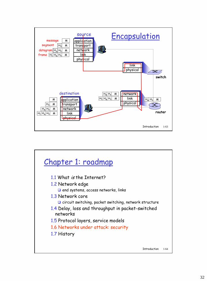
sourceapplicationtransportnetwork
linkphysical
HtHn M
segment Ht
datagram
destination
applicationtransportnetwork
linkphysical
HtHnHl M
HtHn M
Ht M
M
networklink
physical
linkphysical
HtHnHl M
HtHn M
HtHn M
HtHnHl M
router
switch
Encapsulationmessage M
Ht M
Hn
frame
Introduction 1-64
Chapter 1: roadmap
1.1 What is the Internet?
1.2 Network edge end systems, access networks, links
1.3 Network core circuit switching, packet switching, network structure
1.4 Delay, loss and throughput in packet-switched networks
1.5 Protocol layers, service models
1.6 Networks under attack: security
1.7 History
33
Introduction 1-65
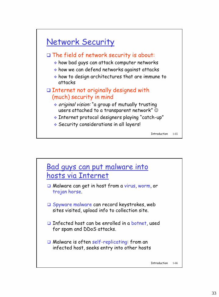
Network Security
The field of network security is about: how bad guys can attack computer networks
how we can defend networks against attacks
how to design architectures that are immune to attacks
Internet not originally designed with (much) security in mind original vision: “a group of mutually trusting
users attached to a transparent network”
Internet protocol designers playing “catch-up”
Security considerations in all layers!
Introduction 1-66
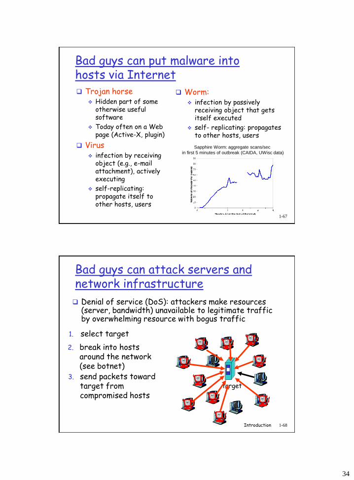
Bad guys can put malware into hosts via Internet Malware can get in host from a virus, worm, or
trojan horse.
Spyware malware can record keystrokes, web sites visited, upload info to collection site.
Infected host can be enrolled in a botnet, used for spam and DDoS attacks.
Malware is often self-replicating: from an infected host, seeks entry into other hosts
34
Introduction 1-67
Bad guys can put malware into hosts via Internet Trojan horse
Hidden part of some otherwise useful software
Today often on a Web page (Active-X, plugin)
Virus infection by receiving
object (e.g., e-mail attachment), actively executing
self-replicating: propagate itself to other hosts, users
Worm: infection by passively
receiving object that gets itself executed
self- replicating: propagates to other hosts, users
Sapphire Worm: aggregate scans/sec
in first 5 minutes of outbreak (CAIDA, UWisc data)
Introduction 1-68
Bad guys can attack servers and network infrastructure
Denial of service (DoS): attackers make resources (server, bandwidth) unavailable to legitimate traffic by overwhelming resource with bogus traffic
1. select target
2. break into hosts around the network (see botnet)
3. send packets toward target from compromised hosts
target
35
Introduction 1-69
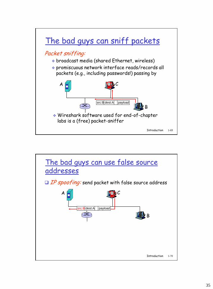
The bad guys can sniff packets
Packet sniffing: broadcast media (shared Ethernet, wireless)
promiscuous network interface reads/records all packets (e.g., including passwords!) passing by
A
B
C
src:B dest:A payload
Wireshark software used for end-of-chapter labs is a (free) packet-sniffer
Introduction 1-70
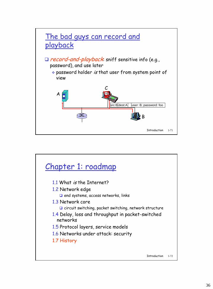
The bad guys can use false source addresses
IP spoofing: send packet with false source address
A
B
C
src:B dest:A payload
36
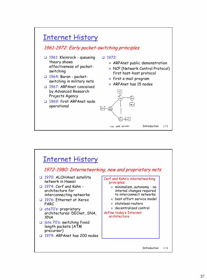
Introduction 1-71
The bad guys can record and playback
record-and-playback: sniff sensitive info (e.g., password), and use later
password holder is that user from system point of view
A
B
C
src:B dest:A user: B; password: foo
Introduction 1-72
Chapter 1: roadmap
1.1 What is the Internet?
1.2 Network edge end systems, access networks, links
1.3 Network core circuit switching, packet switching, network structure
1.4 Delay, loss and throughput in packet-switched networks
1.5 Protocol layers, service models
1.6 Networks under attack: security
1.7 History
37
Introduction 1-73
Internet History
1961: Kleinrock - queueing theory shows effectiveness of packet-switching
1964: Baran - packet-switching in military nets
1967: ARPAnet conceived by Advanced Research Projects Agency
1969: first ARPAnet node operational
1972:
ARPAnet public demonstration
NCP (Network Control Protocol) first host-host protocol
first e-mail program
ARPAnet has 15 nodes
1961-1972: Early packet-switching principles
Introduction 1-74
Internet History
1970: ALOHAnet satellite network in Hawaii
1974: Cerf and Kahn -architecture for interconnecting networks
1976: Ethernet at Xerox PARC
ate70’s: proprietary architectures: DECnet, SNA, XNA
late 70’s: switching fixed length packets (ATM precursor)
1979: ARPAnet has 200 nodes
Cerf and Kahn’s internetworking principles: minimalism, autonomy - no
internal changes required to interconnect networks
best effort service model stateless routers decentralized control
define today’s Internet architecture
1972-1980: Internetworking, new and proprietary nets
38
Introduction 1-75
Internet History
1983: deployment of TCP/IP
1982: smtp e-mail protocol defined
1983: DNS defined for name-to-IP-address translation
1985: ftp protocol defined
1988: TCP congestion control
new national networks: Csnet, BITnet, NSFnet, Minitel
100,000 hosts connected to confederation of networks
1980-1990: new protocols, a proliferation of networks
Introduction 1-76
Internet History
Early 1990’s: ARPAnet decommissioned
1991: NSF lifts restrictions on commercial use of NSFnet (decommissioned, 1995)
early 1990s: Web
hypertext [Bush 1945, Nelson 1960’s]
HTML, HTTP: Berners-Lee
1994: Mosaic, later Netscape
late 1990’s: commercialization of the Web
Late 1990’s – 2000’s: more killer apps: instant
messaging, P2P file sharing
network security to forefront
est. 50 million host, 100 million+ users
backbone links running at Gbps
1990, 2000’s: commercialization, the Web, new apps
39
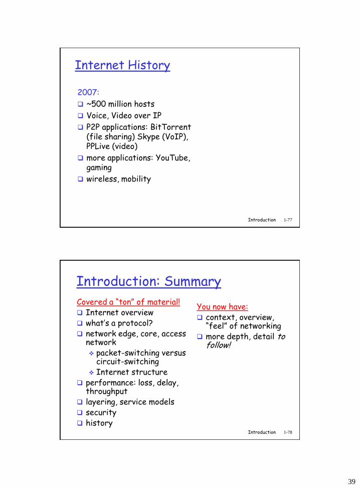
Introduction 1-77
Internet History
2007:
~500 million hosts
Voice, Video over IP
P2P applications: BitTorrent (file sharing) Skype (VoIP), PPLive (video)
more applications: YouTube, gaming
wireless, mobility
Introduction 1-78
Introduction: Summary
Covered a “ton” of material! Internet overview what’s a protocol? network edge, core, access
network packet-switching versus
circuit-switching Internet structure
performance: loss, delay, throughput
layering, service models security history
You now have: context, overview,
“feel” of networking more depth, detail to
follow!