Embed Size (px)
DESCRIPTION
It contains the theory behind gravity, antigravity as well as schematics for gravitational machines and other free energy applications.
Citation preview
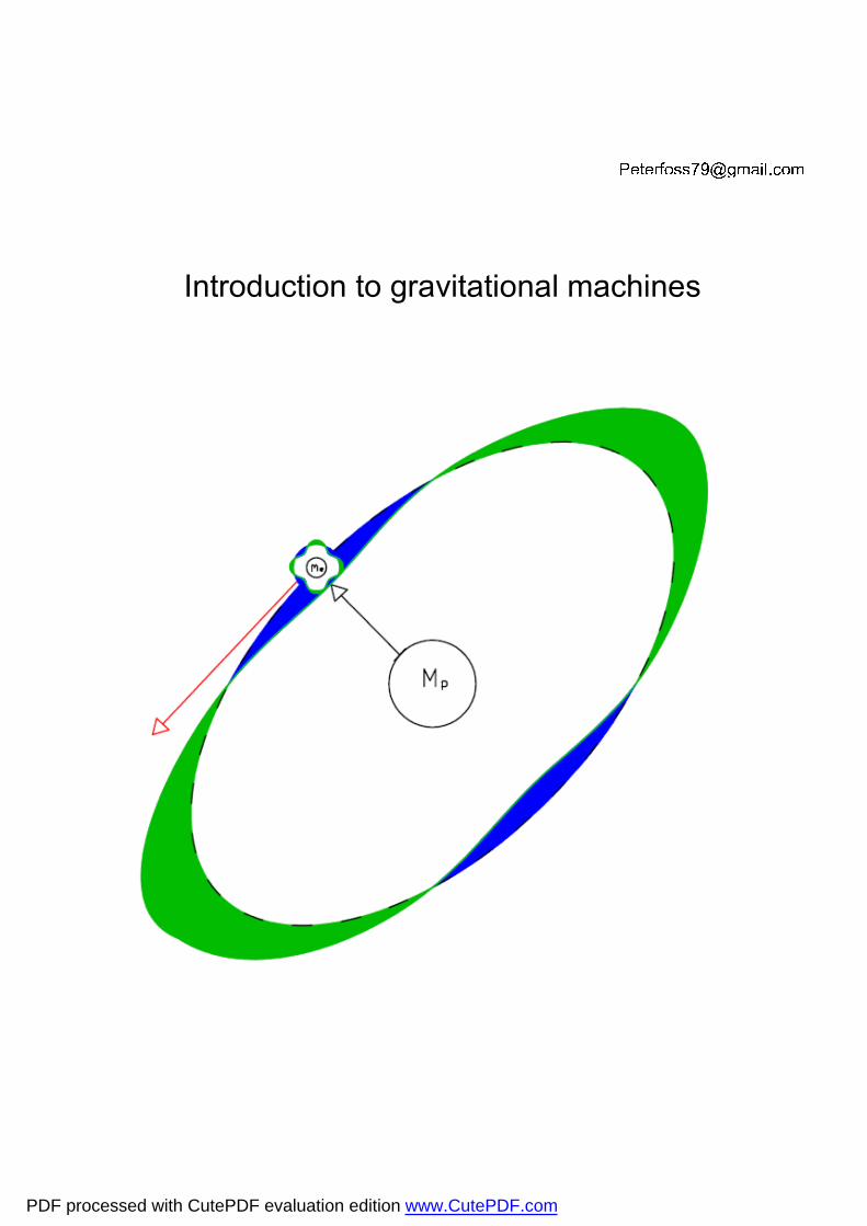
[email protected] Introduction to gravitational machines
PDF processed with CutePDF evaluation edition www.CutePDF.com
This e-book is freely distributable with quotation of the author PeterFoss79


INDEX Introduction 7 Chapter 1: The intuition of the forefathers 11 Chapter 2: Timing is everything 21 Chapter 3: Gray patents (almost) explained 31 Chapter 4: Santagata’s hydrogen 37 Chapter 5: Temperature matters 49 Chapter 6: Tesla and Gray reloaded 61 Chapter 7: Testing the theory with a free energy inverter 75 Chapter 8: A simple gravitational machine XX
APPENDIXES Appendix 1: Images 83 Appendix 2: Gray’s patents 101 Appendix 3: References 141

INTRODUCTION Dear reader I started off my quest for free energy few years ago out of curiosity, without knowing really how far I would make it. Like most people I started following the trail left behind by mythological figures such as Edwin Gray and Nikola Tesla, trying to understand their machines, but moreover trying to grasp the core insight and thinking that induced them to build machines never built before. As I was doing so I studied some new and old electromagnetic theories that once wrapped together would extend Maxwell equations to gravitational fields, explain the operating principle of Tesla and Gray machines and open the way to a whole new chapter of science and technology. The free energy inverter schematics and drafts of gravitational machines hereby explained are published with the spirit of an open source project and it will be very hard to make any patent

claims once they have been disclosed publicly on the Internet. It is not about who gets there first, but about getting there together as a species. I look forward to receive your feedback and suggestions. Peter Foss


Chapter 1
The intuition of the forefathers
“And I’ve always been a nut about thunderstorms. I watched lightning by the hours, I noticed how much stronger it appeared to be when closer to the Earth and just naturally concluded more air had to do with that” Edwin Gray Toward the end of the 60’s, Edwin Gray caught the attention of both media and scientific community with his prototype machines which seemingly defied the basic principles of energy conservation. After his premature and sudden death, all his prototype engines and inverters went lost or confiscated, never to be seen again. Moreover, to date there is no explanation as to why his machines should have worked the way they did. The purpose of this chapter is to unveil the fundamental ideas behind Gray’s machines, and to do so we shall start with the first free energy machine ever built. The first man who stumbled across some unconventional electric machines was Nikola Tesla, with his famous Tesla coil transformer, a version of which is shown in image 1.

Tesla coil cycleTesla coil cycleTesla coil cycleTesla coil cycle The condenser C1 is charged by generator G0 to a sufficiently high voltage ��� until electric breakdown field is reached in the spark gap SG. A certain flow of electrons leaves the cathode C of the spark gap SG as per formula: 1.1. ��� �� �� ��������� With the negative sign meaning that the current is incoming from A into C, or else a stream of negatively charged electrons is leaving cathode C and charging toward anode A of the spark gap. We also note that as far as the condenser C1 is concerned, he is only discharging its current into air, which to him looks as good as the ground potential. C1 is not at all aware of any secondary circuit R2/C2/L2 which may be dampening its discharge current in any way, and this is the reason formula 1.1 only shows R1 and not (R1+R2+L2/C2…). Next step we calculate the current leaving anode A of the spark gap or in other words, the quantity of electrons crossing the gap. This can be deducted out of Townsend formulas for avalanche discharges: 1.2. ��� � ���exp������� � �Μ �
�� ���������; Μ ≫ 1 With α��� being the first Townsend ionization coefficient for ambient air and Μ ultimately being a dimensionless factor greater than one which summarizes the spark gap overall electric gain.
We might expect factor Μ to be somewhere in the range of 10 to 20 even in small, non-optimized systems. To summarize, a small current ��� discharging from the condenser C1 can be amplified by many hundreds of times into ��� by means of a spark gap SG. This amplified surge current was eventually put into use by Tesla through a loosely coupled air transformer L2/L3 in an attempt to broadcast the electrostatic energy accumulated on the top hat of his machine. It must be noted that also the wire employed for the inductance L2 has a certain self or else external capacitance C2 of utmost importance for the correct functioning of the system. How How How How the the the the spark gap spark gap spark gap spark gap performs performs performs performs its magicits magicits magicits magic Let’s now analyze what happens between the terminals AC of the spark gap SG. To begin with, very little current passes between the tips AC of the spark gap SG, only a small amount of electrons leave the conductor due to a feeble thermionic dispersion. They are accelerated toward the anode (cathode C) due to the electric field between AC, but the acceleration is not strong enough to ignite a spark and shake apart the molecules of interposed gas. At some point the gas dielectric rigidity, also known as breakdown electric field, is reached
(image 2). For air at standard conditions (1 ATM and 0 Deg C) this breakdown electric field is equal to about: 1.3. ����� !"#$%&' � 3.0+, � �
$� With V�� being the max voltage achieved into condenser C1 just before the discharge cycle begins, and ��� being the distance between the tips AC of the spark gap immersed in standard air. When C1 begins its discharge, a handful of electrons leaves the cathode (tip C, image 2 part 2) and charges toward the anode A with a certain acceleration due to 1.3. 1.4. �.� � �� ∙ �0 (electric charge leaving cathode C) 1.5. 1�!2 �3������� !"#$%&' ∙ 456 7!28 (acceleration of free electrons �.�) These free electrons are accelerated only up to a certain velocity before they smash and slow down against some air molecules which happen to be in their path (image 2 part 3). These air molecules are electrically excited so to generate the characteristic lighting glow: 1.6. 9:∗ → 9: = >?

But some of them are ionized, with generation of additional free electrons and cations as per this very simplified reaction: 1.7. 9: = 45 � 9:@ = 245 This last formula explains how the free electron generation progresses in a chain reaction fashion. The much slower cation molecules 9:@ are lagging behind the electron cloud and they generate a counter electric field which tends to slow down the electron cloud (image 2 part 4) thus moderating the chain reaction. This process keeps escalating until an avalanche of electrons finally reaches the anode A of the spark gap (image 2 part 5). 1.8. �.� � �� ∙ �0 � Μ�� ∙ �0 � Μd.� All these electrons can easily permeate inside the anode A whilst the air cations cannot diffuse into solid material and are stuck in the atmosphere just outside the conductor. This entire process is what Gray referred to as “splitting the positive”. To note that the formulas to calculate the acceleration of the air cations are: 1.9. 1�C�D � 3������� !"#$%&' ∙ 4@6 7C�D8 1.10. 7C�D � 18367! 3GHIJ4KL0>C�D6 � 5.14� = 47!

As we can see, the mass of these heavy air molecules is so much bigger as compared to the mass of the free running electrons, that the acceleration of the cations is matter of factly negligible (more than fifty thousand times smaller than the acceleration of electrons). It must also be noted that the electric charge �.� crashes into A with a small delay OP from the time �.� leaves cathode C, this because the speed of the electrons between C and A is finite due to the average migration velocity of free electrons wriggling their way across air molecules. Thus considering image 3 we have: 1.11. �!�QR2 � ST�U2: � "��S2
: V�W � X"��S2: ��W, being 1.12. V�W � $�QR�QR 1.13. OP � $�Y
S�QR2 The factor ��W is the average distance an electron can freely move and accelerate before impacting & stopping against a static air molecule. How did they get that idea?How did they get that idea?How did they get that idea?How did they get that idea? Let us take a look at image 4 showing a lightning.

The flow of electrons begins in the upper atmosphere, it tends to stay compact inside a single branch. This fact can be explained due to both low air gas density and higher average electron velocity, so the electron multiplying process cannot escalate (formula 1.7 pretty much balancing itself). When the electron shower finally approaches the lower atmosphere, air density increases and formula 1.7 can now start an abundant chain reaction, which generates a great numbers of free electrons, all charging toward the ground. The heaviest air cations are lagging behind in the upper part of the atmosphere. These cations generate a counter electric field which slows down the electron cloud and tends to quench the spark. Since the electron gas density is increasing at lower altitudes, the electron flow tends to branch out due to self-electrostatic repulsion. Back in the days, engineering schools were much more unsophisticated as compared to the ones we have nowadays. The poor guys, Tesla and Gray, hadn’t been briefed about the law of conservation of energy nor about Townsend experiments, so when they saw a lightning they saw something which could turn a small incoming current into a much bigger one, hence their machines deploying spark gaps as an active electricity generators.
This idea looks somewhat naive when put in front of a detailed first principle examination. In fact the electrons gathered at the anode will be available at much lower absolute voltage than the one at the cathode, so this electrostatic charge is much less capable of yelding a power output, in fact it will eventually produce a power output lower than the power required to feed the primary side of the system. Still the question remains, why should Gray and Tesla machines have worked the way they supposedly did, why did they invest so much resources and even bother to patent some of these applications?


Chapter 2
Timing is everything
I libri dei padri e delle madri (di qualità inferiore!) parlano meno dei buoni morti. Paulo Difficiliora Image 5 and 6 show how voltages and currents go in and out of the main components C1, C2 and L2 during a full cycle time T of the system. The primary circuitThe primary circuitThe primary circuitThe primary circuit There are four main phases for the condenser C1. 1) Primary circuit discharge phase. It starts when it is fully charged and capable of igniting the spark ���. This current is magnified as it crosses the gap CA, then sustains and ultimately quenches, leaving capacitor C1 partially charged. 2) Primary holding phase. Condenser C1, not fully discharged, simply holds its charge and voltage still.

This is to prevent the ignition of a second spark before the secondary circuit is ready to begin another cycle. 3) Autocharge or primary fast charge phase. During phase T3, some spare current from the secondary circuit can be recycled back to the condenser C1 to minimize recharge time and energy requirement from the generator G0. This phase will need some additional circuitry as we shall see in chapter 3, and it could also be swapped over with phase 4. 4) Slow or else final charge phase. In the last part of the cycle, generator G0 starts recharging the condenser C1 toward its final firing voltage to start a new cycle. The secondary circuitThe secondary circuitThe secondary circuitThe secondary circuit.... The secondary circuit can be any combination of capacitive, inductive or resistive load. There are up to four main sequences on this side of the system. 1) The lagging phase. The secondary circuit is fully discharged, there is no current passing through the components since the electric charge �� is still wriggling its way through the air in the spark gap. The length of this holding phase should be as short as reasonably possible depending on design considerations of the spark gap as outlined in chapter 1.
In most of the low frequency applications this time delay can be assumed 0, but it is relevant in systems operating at high frequencies. 2) Charging phase. It partially overlaps with the next step, and it nominally ends when the full current ��� has entered into anode A. In this second phase, anode A starts to receive the full current ���, many times greater than original current ��� from the primary. The multiplying factor Μ could be assumed constant or variable with the voltage ��� which is not constant during the discharging phase of the primary condenser C1. If the condenser C2 was equal to 0, the received current would quickly charge anode A to a voltage possibly even lower than ��, before the inductor L2 could release the charge to ground port G2. If this happens then the spark would suddenly quench in Tau 1 or even partially repel incoming current ��� (secondary electron emission) rather than prolonging the cathode charging phase into Tau 1 + T1 to receive max charge available from C1. If this is the case then the factor Μ drops although the received charge �� is indeed available at voltages eventually higher than the one in C1. On the contrary, if the condenser C2 was infinite, the charge �� collected at the anode A would be available at a negligible voltage, thus the energetic potential of the charge �� would be too watered to generate significant power through L2.
Load L2 and C2 must be matched so to adsorb as much current ��� available at the lowest voltage �� possible, without repelling or else quenching the current ��� too quickly. 3) Discharge phase. Here the load L2 finally gets to regime and it sucks out the stored charge �� off the condenser C2. If load L2 is too big as compared to charge/voltage available, then C2 will take a long time to discharge through L2, overall cycle time will get longer and power output of the system will be lower due to increased cycle time T. Max power off the circuit is attained when the inductance L2 fully discharges itself at the right time T. 4) Overshoot phase If load L2 is lower as compared to the available energy in secondary circuit, then the inductor L2 will overshoot and possibly cycle some charge back and fro through resistance R2 to condenser C2. This will cause dissipation of available energy into resistance R2 and cause a spark anticipation, like a piston engine knocking, leading to sudden and potentially devastating secondary circuit overheating (seemingly Tesla destroyed quite a few of his prototypes before he could properly tune the current and voltage overshoots). A diode D2 is envisaged to mitigate this potential issue.
Detailed sizing of all system components can be finalized and optimized once spark gap characteristic parameters Μ and � are established. Energy balanceEnergy balanceEnergy balanceEnergy balance As the secondary circuit receives the current ���, the voltage in A decreases with a curve specific to the particular configuration L2/C2/R2. The energy balance of the secondary circuit in one operating cycle is defined as: 2.1. �� � � �� ∙ ��������� So it is important to have the lowest value of �� and highest value of �� (biggest spark gap possible, compatibly with the size and max voltage of the primary condenser). In a nutshell: low capacitance C2 causes lowest voltages �� but also low charge available ��. The overall gain �� � �� �⁄ might seem high but the specific power of the system will be lower as compared to same system with a greater C2 which is allowed to receive a greater charge �� but at averagely lower voltages ��. The most important parameter of the system is the overrunity factor OF which is defined as: 2.2. �� � ����������
���∙���� !���∙���� !�
� ���� !����� !�
The factor ���� !����� !�
is usually lower than 1 although it could spike above 1 during abnormal
operating conditions. We then introduce the system voltage efficiency defined as: 2.3. "� ����� !����� !�
So the gain factor in 2.2 can be summarized as 2.4. �� � Μ"� This last formula tells us that the free energy gain factor of the system depends upon design parameters of the spark gap (Μ), as well as design considerations on the primary and secondary loads ("�), or so it seems if we stay within the boundaries of classic electromagnetism as Gray and Tesla did when they begin to build their prototypes. Needless to say that from a rigorous analysis against the first principle of thermodynamic, once accounted for the heat losses across the air, heat generated by the spark, energy required to tear electrons off the catode and heat of electrons upon impacting on the anode A, our glorious overrunity factor would always be lower than 1, which means our machine will not yield any free energy. Ever! We shall see later on how the impact heat generated on the anode A by �� will be the key to bump 2.4 well above 1, thus yielding an output tens of times greater than the original input

energy.


Chapter 3
Gray patents (almost) explained
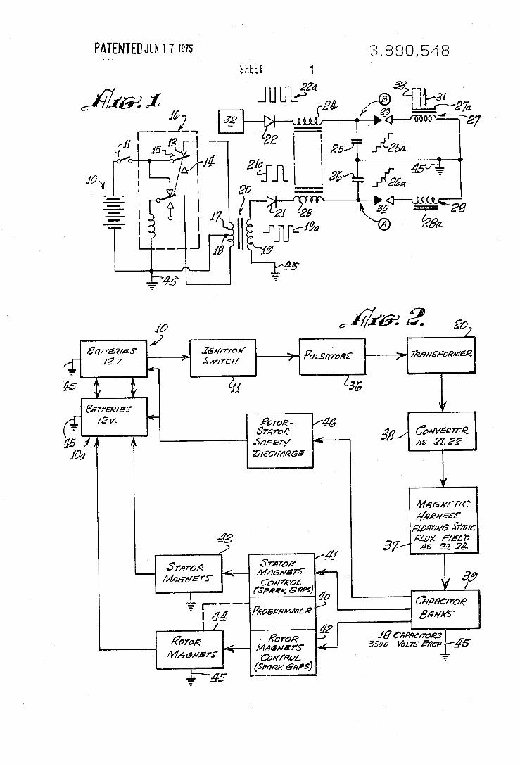
The bulb lit, then Gray dropped it into a tank filled with water. “What would be happening if this was getting ordinary power right now?” Gray asked, as he stuck his hand in the water with the glowing light bulb. The National Tattler I invite the reader to take a look at appendix 2, containing Gray patent literature available from the Internet, it will be a lengthy yet enlightening exercise. Both Tesla and Gray machines originally started from the basic concept of a spark gap Overrunity Factor as explained in formula 2.4, which they tried to exploit in a number of ways. Patent 1: Patent 1: Patent 1: Patent 1: Tesla/Gray inverterTesla/Gray inverterTesla/Gray inverterTesla/Gray inverter In image 7 we have some improvements as compared to the original Tesla coil design, mostly owing to the fact that Tesla did not have power diodes available back in his days. For instance we have a switch S0 which can manage the holding and slow charge phase of the primary circuit. We also have a switch S2 which reroutes the exhaust current from the secondary circuit back into the primary condenser C1 thus reducing the power draw from generator G0.
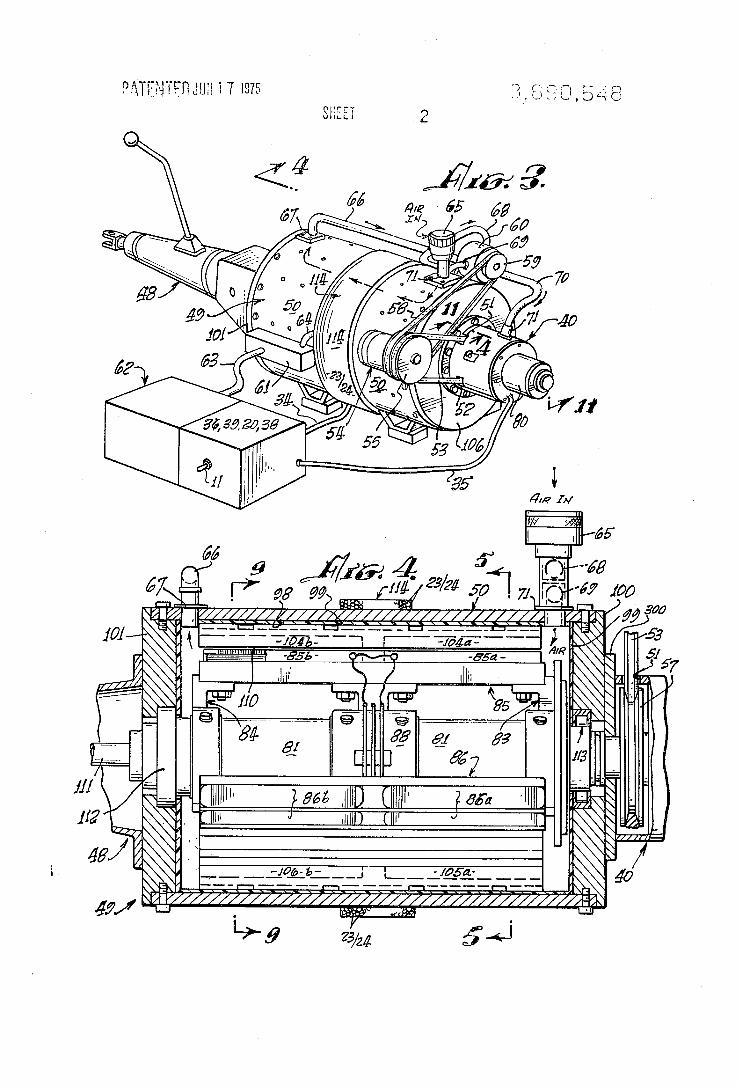
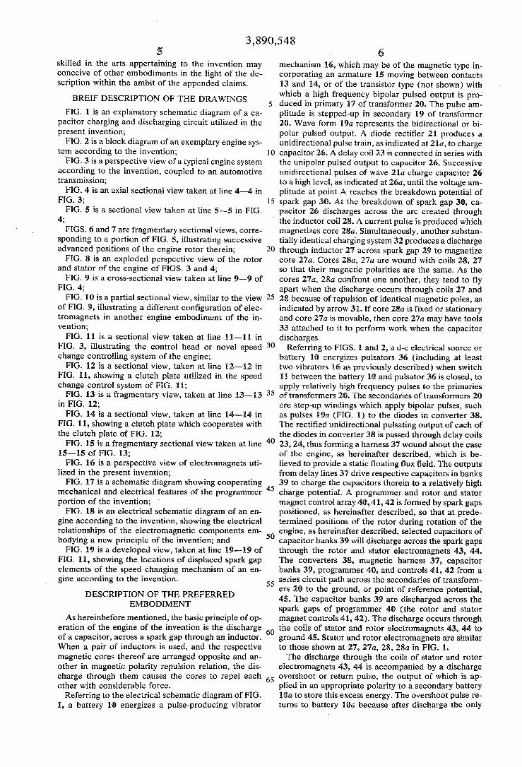
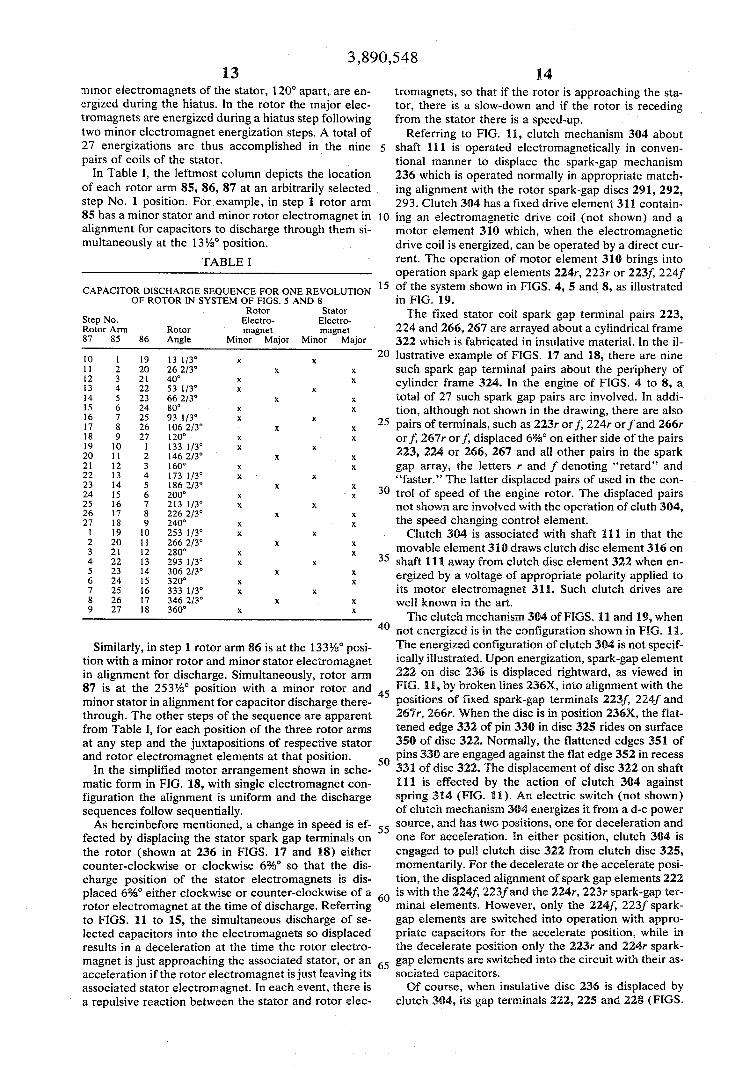
There is a switch S1 which isolates the spark gap when the primary is fast charged through switch S2 thus preventing “spark knocking”. A new diode D2 is also present to prevent overheating of the secondary circuit, it could eventually be connected to ground to avoid backcharging of C2 during the overshooting phases, however C2 back charging could be desirable to lower the recharge power to C1… Gray inverter (first patent) is a clever simplification of the circuit shown in image 7. The operating cycle of Gray inverter is dully explained in the patent, but he is not showing the grounding ports which are fundamental for the operation of the system. Patent Patent Patent Patent 2222: : : : EMA motorEMA motorEMA motorEMA motor This patent has some thrilling electro mechanic going on in regard to spark gap timing and operation of multiple coil circuits in different configurations to change the speed of the rotor. A part from that, it resembles a synchronous motor exploiting the gain factor of a sparked electric current which powers up the magnets of what is ultimately a synchronous motor. An air pump was needed to “cool the rotor/stator”, but most likely the air was also necessary to feed the spark gap array with fresh fuel (air).
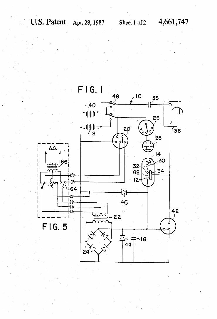
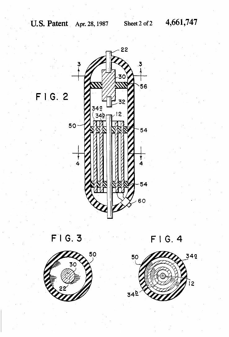
Patent Patent Patent Patent 3333: : : : VVVVacuum tubeacuum tubeacuum tubeacuum tube inverterinverterinverterinverter This patent (image 8) is clearly a game changer as compared to the previous straightforward designs. Main peculiarity here is that the spark gap is now a spark tube in vacuum, so the current is not amplified by the molecules of the gas (M = 0!!!!), but it is in fact the secondary electron emission charge of the high voltage anode toward two collecting plates. The main omission in Gray’s patent here is to show only one terminal connecting both collecting plates inside his vacuum tube (my mark ups are shown in red). According to Gray’s description of the device, the inner plate 34b should in fact collect the emitted electrons of anode 12 toward the inductive load 36, whilst the outer plate 34a should be connected to ground, thus forming a condenser assembly with the inner plate 34b in order to smoothen surge currents and voltages and to protect the inductive load. The operating cycle is dully described, and all this needless sophistication doesn’t explain why the device should produce more energy than it adsorbs. Wireless electricityWireless electricityWireless electricityWireless electricity applied to light bulbsapplied to light bulbsapplied to light bulbsapplied to light bulbs Another thing that cannot be explained in terms of amplified sparked current is Edwin Gray demonstration of the bulb experiment in the water tank, which was somewhat similar to Tesla experiment lighting a mercury vapor bulb wirelessly.
Last clue is that reportedly, Edwin Gray machines were emitting an outgoing magnetic field all around them, as if magnetic monopoles were being generated by the machine. Since classical electromagnetism cannot predict nor explain such machines, it is time to go and look for other equations which could explain these phenomena without contradicting but integrating our knowledge of electromagnetism.


Chapter 4
Santagata’s hydrogen
If you eliminate the impossible, whatever remains – however improbable – must be the truth Sherlock Holmes Carlo Santagata was an Italian engineer fairly active in physic research and member of the Physic Society. He wrote quite an amazing book: The unification of electromagnetic and gravitational fields – Gravitational waves and antigravity. Unfortunately Santagata didn’t live to complete the second part of this fundamental theory, but still he put forward enough information for us to close the circle. I will hereby provide a simplified explanation of his work as well as some extensions and deductions starting from his formulas. Again I strongly recommend the reader to lookup for Santagata’s original work which will provide an extremely accurate and rigorous description of some of the things I am going to dully explain in this chapter.

To begin with, mass does not exist, but it only is an indirect measure of a particle magnetic moment potential. Every particle only bears its own electric charge, and is magnetic moment potential, indirectly measured as a mass or else gravitational field. For an electron orbiting a proton like on image 9, it means that this particle can only collapse so far toward the atom nucleus before its centrifugal force (related to its mass) balances the electrostatic force (related to its charge), thus generating a magnetic pole whose value is strictly dictated by the dipole specific mass/charge ratio. Even an isolated electric particle at rest, does not necessarily have a charge homogenuously distributed like classically assumed, but it is eccentric instead and it spins within its own classic radius as much as needed in order to maintain its internal magnetic moment potential. Assembling a protonAssembling a protonAssembling a protonAssembling a proton A practical explanation of what we have just said is given in image 10. The electric charge of a proton is not evenly distributed, but it is eccentric and rotating within its nuclear radius so to maintain a certain magnetic moment. As a consequence of this fact, the electric field radiated at a certain radius r from the particle will not be stationary but it will flicker and fluctuate with the same frequency of the inner charge: 4.1. ������ � ���
��� �1 ��������� sin��������� ��������� 4.2. ������ � ����!� �����"� 4.3. ����!� � �
�� ��� Coulombian electric field

4.4. ����"� � ���
��� �������� sin��������� ��������� Gravitational/reactive electric field We can then say that the gravitational field radiated by the particle is in fact a very tiny reactive electrical field as follow: 4.5. #���� � �
�� ��� ��������
��$ %sin��������� ���������%
�& '� � (
�
�� (�
� 4.6. ) � *
+,�-.,/�
√1 This is valid for purely sinusoidal reactive electric fields In In In In fact gravity isfact gravity isfact gravity isfact gravity is dimensionally dimensionally dimensionally dimensionally like an like an like an like an electric fieldelectric fieldelectric fieldelectric field, it is the , it is the , it is the , it is the effective effective effective effective ((((rms) rms) rms) rms) value of the value of the value of the value of the reactive reactive reactive reactive part of the particle electrostatic fieldpart of the particle electrostatic fieldpart of the particle electrostatic fieldpart of the particle electrostatic field!!!! The reactive field itself might also have a simply sinusoidal shape or otherwise be composed of more harmonics depending on the complexity of the subsystems making up the particle or atom, but ultimately the effective value and main frequency is what characterize the gravitational behavior and interaction with other particles. This theory has been used by Santagata to explain and predict many physical phenomena such as: 1) Variation of geomagnetic fields due to moving gravitational bodies. 2) Prediction of the Sun Wolf number against the masses and orbits of the Solar system planets.

3) Prediction of the elastic module for solid materials as a simple function of density, molecular weight of the material and crystalline structure shape. 4) Prediction of the speed of sound for both solid and gas media as a simple function of density and molecular weight. 5) Explanation of the Casimir effect. 6) Deduction of the adimensional gravitational/electrical force ratio for protons. In fact Santagata uses this residual/reactive electric field (or gravitational field) to explain any aggregative state of the matter, from the quarks up to the galaxies, and it is fundamental for us to go through this imaginative exercise together in order to better understand the implications of such a revolutionary theory. Assembling a neutronAssembling a neutronAssembling a neutronAssembling a neutron Someone might say that since the neutron has no electric charge to swing around and ‘bout, then its nucleus should radiate no gravitational field, but in fact the neutron is like a proton with a negatively coated shell which gives an overall null Coulombian electric field but still issues a flickering reactive electric field as per 4.4, hence its gravitational field is radiated similarly to the one of a charged proton (image 10). Assembling an hydrogen atomAssembling an hydrogen atomAssembling an hydrogen atomAssembling an hydrogen atom

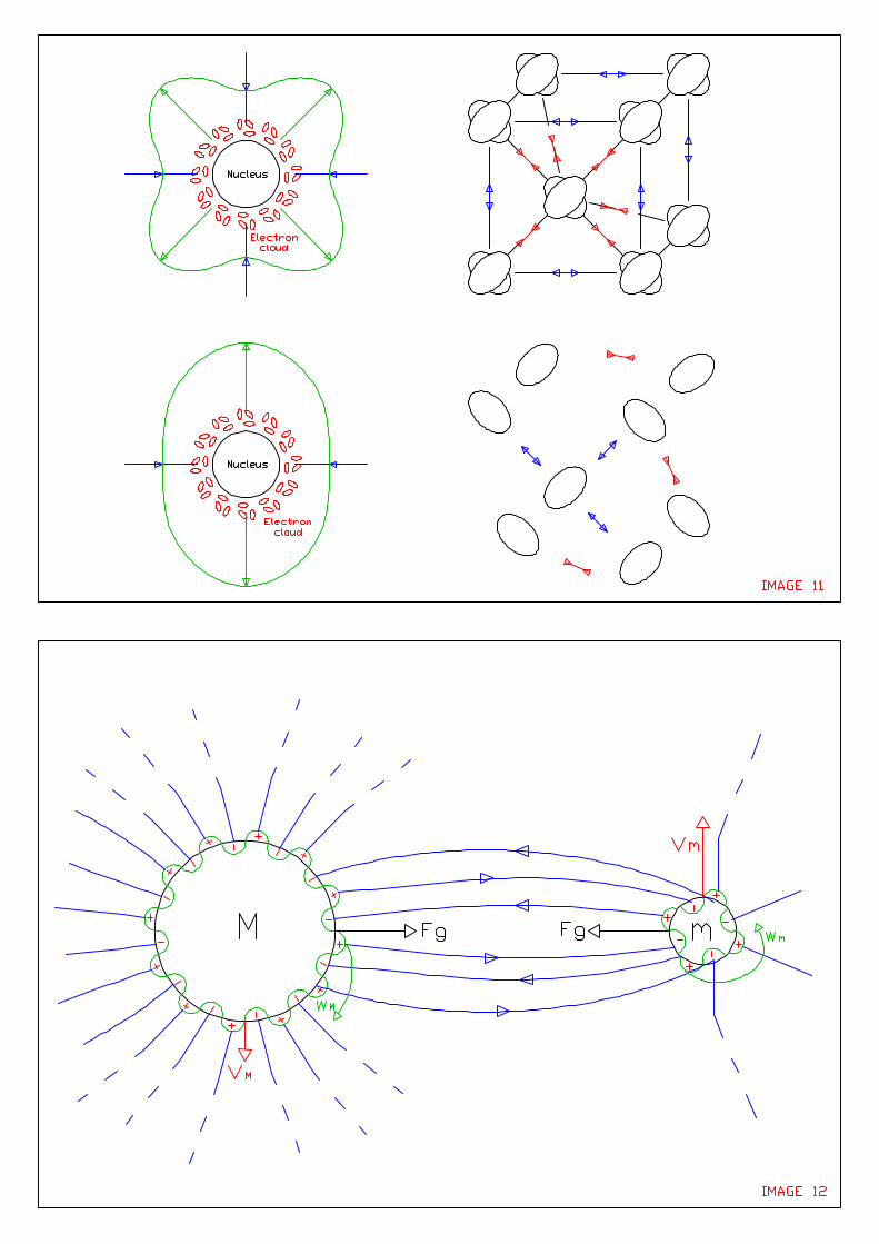
When we put together a proton and an electron, we don’t just add up the masses (reactive electric fields) of the base particles, but we also put an electron into orbit, and this orbiting effect causes some additional ripples and flickering of electric field being radiated outside the atom, so the total mass of an hydrogen atom is slightly higher than the sum of the rest mass of a proton and electron. Similarly, when we push that electron up toward higher orbits, we also increase the eccentricity or magnitude of �������� so that the atom will appear a little bit heavier than before... The concept of electric charges forced within highly eccentric orbits is of utmost importance to understand gravitational machines and to generate and focus gravitational fields in specific directions. Assembling a solidAssembling a solidAssembling a solidAssembling a solid matrixmatrixmatrixmatrix As explained in figure 10, the flickering electrical (gravitational) field has its own shape, which is eventually a function of the atom’s temperature. Within a solid, the atoms are cold enough to exhibit a tetragonal shaped reactive electric field as per image 11 top part. This helps to explain why they all wish to fall within right electro/gravitational equilibrium positions of a tetragonal matrix which minimizes the overall potential like Lego blocks clicking into their only possible position.

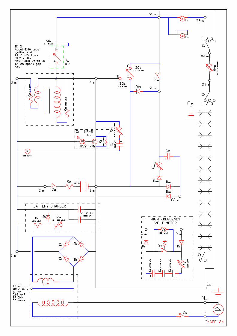
Assembling a Assembling a Assembling a Assembling a gasseous matrixgasseous matrixgasseous matrixgasseous matrix If the atom is hot enough, the shape of its gravitational (reactive electric) field changes from tetragonal into a more unstable cross like shape (image 11 lower part). This means that even if such an atom can find a couple of peers to neutralize a couple of its electric arms, there will be other atoms around them which will jump in and disrupt the links previously formed, which means all the atoms are unable to cut an electrically (gravitationally) stable deal with their neighbours and this overall electric unbalance results in a repulsive expansive force for all the gas atoms or molecules (antigravitational/repulsive reactive field). As the gas is let free to expand, it also cools down, which means that its atoms will sooner or later end up with a residual electric (gravitational) field shaped as per the solid matrix. This observation predicts that a gas let free to expand shall not expand forever, but only until a thermal / electrical (gravitational) equilibrium is reached in order to form a matrix similar to a solid one, only much less dense and structurally weaker than the solid matrixes we are used to. This phenomena is otherwise explained by astrophysicists as a “dark matter” gravitational glow capable of holding interstellar gasses together more than what they should. Assembling a solar systemAssembling a solar systemAssembling a solar systemAssembling a solar system Image 12 summarizes the gravitational interaction between two massive bodies, only that the gravitational field is in fact an electric one.
One thing to visualize is that the reactive electric fields of the two masses are rotating in perfect synchronism like gears meshing together. If the kinetic energy of say the smaller mass m was higher, then the rotation of its gravitational gear �� would be slower than the rotation �2 of the gears in M, which means the equilibrium position of the two masses will happen at a greater distance. RRRRelativisticelativisticelativisticelativistic massmassmassmass When at rest, the orbit of the electric charge inside its nucleus is simplified as plain circular (image 13 top left side). If we then accelerate that same particle to relativistic speeds, the internal charge keeps rotating around the nucleus, but it is now in an awkward relativistic situation in which the forward rotating speed 3��( is to be mitigated to avoid faster than light speeding tickets, which means the charge must make up for the lost time by speeding up and increase its backward speed 3��4. We end up with a relativistic situation where %3��4% ≫ %3��(%, so the eccentricity of the orbit is extremely high, which also means the reactive electric (gravitational) field emitted by the particle is extremely high, which means its apparent mass is higher than the same mass at rest. Unification of the forces of natureUnification of the forces of natureUnification of the forces of natureUnification of the forces of nature Depending on the scale we look at, the gravitational or else reactive electric field is the cause of all the known forces of nature which distinguish themselves only as a function of the particle
temperature. It will be very strong on a small scale (atomic forces) and a bit less strong on a molecular or solid matrix level (London forces), and less strong still on a planetary level (gravity), and even less strong on an intergalactic / gas dust level (dark matter), and so forth… What about the inertial mass?What about the inertial mass?What about the inertial mass?What about the inertial mass? In his book Santagata promised to give charges to the masses, which is what we just did in 4.6 but still he promised to give masses to the electric charges, which boils down to the inertial mass problem: 4.7. 6� � )7� This equation is obviously working in a number of technical applications and does not need any electric charge to explain itself, so at last mass seems to be an electric charge independent property of particles. Nevertheless, what was recognized and later proved back in the 1881 (J.J. Thomson) is that it is more difficult to accelerate an electrically charged body than it is to accelerate the same but uncharged body. This fact is simply explained in terms of self magnetic induction of the charged body, which behaves like an electric current when it is set in motion and the induced magnetic field generates an additional electromagnetic resistance to the acceleration of the charged body.
We could simplify this concept in the following way: 4.8. 3 � 8 9:9;
� (<� 4.9. 6 � * =
<9:9;
Here the inertial mass has been replaced by an electric charge and its self induction coefficient, and this fact has been furthermore explored by some researchers who tried to calculate the self induction coefficient of the electron which ultimately brought the following conclusion: 4.10. )�>�<�?;�@�A"B�;:? �
C)�>:B��;:A< So the theoric calculated self induction electric dependent inertial “mass” of an electron is 33% higher than the actual/measured inertial mass value of that particle. This result, although not satisfactory, comes very close and moreover through a clean 4/3 ratio to predicting the actual electron inertial mass value. Also we wonder if there is space for a classic Newtonian inertial mass at all inside the electron, since the particle does have a self induction coefficient which opposes changes of velocity in accordance to 4.9, regardless of our mathematical capability to accurately predict that value. Last suggestion is that electromagnetic and inertial masses might come to fully coincide once the electric charge eccentricity is accounted into the electron model.


Chapter 5
Temperature matters
The Schrodinger cat walks in a bar and… …it doesn’t! As per before, we can conclude that gravity is that residual electric force which pushes or pulls particles toward their equilibrium distance. That equilibrium distance depends upon the rotational kinetic energy or rotational temperature of the particles being examined. Gearing fieldsGearing fieldsGearing fieldsGearing fields The gravitational fields of each particle perfectly mesh into each other when the particles are held at the right electric and kinetic equilibrium distance such as the electron in image 10, gravitationally surfing on the field radiated from the proton. However, if the electron (or else the proton) spin is rotationally (thermally) excited then a new equilibrium distance will be forced upon the system (image 16).

Also looking at image 14 we could summarize the gravitational force between two electrically charged particles in the following way: 5.1. ������ �
�
��� ����
��1 ��������� sin� �������! �"�������#$�1 �
�%������ sin� %������! �"%������#$ & 1' 5.2. ������ ��
��|� ��|
����%������ cos +������� The newly introduced cos +� factor summarizes the direction of the gravitational force between two particles, and it can vary between 1 or -1 (attractive or repulsive), whilst the term ��%������ suggest that a particle apparent gravitational field can be enhanced to values far greater than their minimum thermal value and it is directly related to the eccentricity and magnitude of the unbalancing charge. The theory requires the electron particle itself to have a small, positive electric charge nested within it, similarly to the proton structure shown in image 14. When the gravitational field frequencies are perfectly tuned into each other (cold systems) then
cos +� is simply attractive (image 15 top part), the centrifugal force balances the coulombian force and the system is in electro/kinetic equilibrium. The system could however be excited so that the fields do not properly mesh into each other, then cos +� might change so the gravitational force favors and enhances the centrifugal one. This leads the electron toward outer orbits (central part of image 15 and also image 16).

On the other side, if the orbiting particle is too slow, then cos +� will vary again, the gravitational force will be weaker than the electrostatic attractive force and it will bring down the particle toward an inner orbit. By exciting a particle spin frequency or else charge eccentricity (mass!) we can forge attractive or repulsive gravitational fields as compared to particles which tune in at similar frequencies. The difference between a gravitational attractive force versus its repulsive expression is mediated by the phase angle between the electric reactive field and the particle electric dipole phase angle. We must also note that despite the neutron being an electrically neutral particle, it must be considered like a proton as far as gravitational fields are concerned as explained in the previous chapter. Also the thermal energy of a particle brings upon many agitation modes within the same, but the ones which enhance the spin of the inner electric dipole are the one most relevant for the generation of strong gravitational or anti gravitational fields. Have you ever seen a lighting ball?Have you ever seen a lighting ball?Have you ever seen a lighting ball?Have you ever seen a lighting ball? If you have never seen or heard of it please look it up on Youtube or Wikipedia.

Such a strange and unexplained phenomenon can be better understood with what we have described so far, Let us take the nucleus of a heavy atom and thermally charge its magnetic momentum so that the spinning velocity of its inner charge is as close as possible to the speed of light. The Coulombian electric field will behave business as usual, but the reactive electric field will be extremely strong and spiky, like a sea urchin (image 17). This means that the gravitational equilibrium distance of the cold/unexcited orbiting electrons will be very far away from the nucleus, in the order of few centimeters. Unfortunately, the lighting ball is not an isolated object, it is surrounded by pressurized atmospheric air, which will try to enter inside the lighting ball to fill the void between nucleus and electron orbits. As fresh air pours into the lighting ball, it is exposed to highly ionizing gravitational repulsive winds which prevent electrons of air molecules from approaching the center of the ball, thus generating a ionizing wave which pushes exhausted air ions and related electron clouds outward again with a spectacular emission of light. Eventually, the excited nucleus at the center of the lighting ball will decay its extremely high spin velocity down to more sociable thermal kinetic energies, so the glow fades and the show ends. An alternative ending is that as the nucleus cools and slows down, it passes through a velocity

state resonating with the velocity holding up its very same atomic structure to the point that it explodes suddenly. This is more likely when the nucleus is a heavier atom, since its atomic structure is somewhat weaker than smaller ones. Super electronsSuper electronsSuper electronsSuper electrons Like for the lighting ball, overexcited “super” electrons are extremely antisocial toward the other particles, especially electrons. It is reported that Tesla was generating quite a few of these during his experiments. These should look similar to what we have described for lighting balls, only that now it is the electron which will look like an urchin, and probably the diameter of the ball will be smaller. When these are forced into a metallic matrix, they might not have enough antigravitational force to explode the robust metallic matrix in which they dwell, but still they can bully nearby electrons in the metallic structure and keep them at bay in virtue of a highly repulsive reactive electric field (image 18). A metallic material irradiated with super electrons will exhibit an extremely low voltage as compared to the ground because normal electrons cannot spread evenly within the conductor volume, they are forced and squeezed into a smaller material volume and they will concentrate on the body surface.
In this case the metallic conductor will appear extremely negatively charged, thus making the conductor highly ionizing in air and behaving in fact like an energized condenser. Again the super electrons will ultimately decay their spin energy down to thermal energies and the effect will fade, but we now have the key with which we can interpret both Gray and Tesla wonder machines. Also when we look at image 18, we could draft the values of the superficial electric field radiating from the conductor surface (image 19 top part). To begin with the conductor has no electric field, then when the super electron enters into it, the electric field quickly drops down to a very low value. As the superelectron cools down, the electrostatic pressure on the surface drops too and if the effect is due to a multitude of superelectrons we can then imagine this process to develop like an exponential decay until in T3 all the superelectrons have faded and the field is back to 0. We can go further and develop the displacement current integral as follow: 5.3. ,-.-∯01��
02345 � ∮ 7389 That formula can be developed into an average/constant displacement current field as well as a reactive displacement current field (Image 19 lower part). The average part of this field is capable of inducing electric currents in conductors approaching
or leaving the proximities of the supercharged conductor, with the currents being greater the faster the conductor is moved about. This is important to bear in mind since human body is a good conductor, and also Tesla personnel seemed to have suffered injuries during some experiments! The reactive part of this field could furthermore be used to power up specially designed transformers placed nearby the supercharged conductor. Magnetic monopolMagnetic monopolMagnetic monopolMagnetic monopoleseseses This is a part of the Gray machines which cannot be explained so far, I will try to bridge this as a pure hypothesis. In image 20 the orbit of the particle charge inside the nucleus is so energetic to be totally warped and twisted due to extreme thermal charge. The resulting spires of this quantic coil (not easy to draft but take this leap of faith with me) are so wired together to result in an “all out” radiating magnetic field, same as a magnetic monopole. Another possibility is that the conservative magnetic field is in fact an electromagnetic fingerprint or radiated energy field due to superelectrons decaying back into their normal electron state. The generation of magnetic monopoles, although not clear, will be needed to explain

exceptionally high torques present into the EMA motor as well as reported experimental measurements done on Gray machines. Also we would have to assume the speed of superelectrons in conductors being much greater that the speed of normal electrons within the same which is usually in the order of only few millimiters per seconds. Perle ai porci.Perle ai porci.Perle ai porci.Perle ai porci. Another interesting prediction is that the gravitational field of a body changes with its temperature or else spin kinetic energy, with hotter bodies appearing somewhat lighter than their equivalent cooler version. This is explained by formula 5.2 and the deduction that a cooler body tends to synchronize the reactive electric field of all its sub particles so to add up a stronger reactive (gravitational) field. On the other side, the particles of a hot body cannot efficiently synchronize and add up their reactive electric fields, so the total reactive electric field (gravitational field) measured outside the body will be lower than the geometric sum of the gravitational fields of all its particles, as if the total gravitational field had a lower “power factor”. From a universe point of view, the expansion of the same is related to its mean temperature, and as it cools down, it tends to slow down and arrest its expansion. When the universe is cold enough, it will subsequently tend to condense (contract) back into a more dense and concentrated equilibrium position.
We can also deduct that the fine structure constant is in fact the expression of a gearing factor or else ratio between the angular velocity or spin of two electric charges against their coulombian attraction force.


Chapter 6
Tesla and Gray reloaded

Gray: If only you had had power mosfet, we would be 120 years more advanced. Tesla: Quite the contrary, I would have blasted it all before you could have said EMP… Gray & Tesla In our previous chapters we have gathered all the electromagnetic ingredients we need to cook both Gray and Tesla machines, let us start from image 8. Please note the schematics shown here have been edited by myself in red, as they seem to be somewhat incomplete, possibly an attempt of Gray to cover up his tracks and prevent other people from copying his inventions. The mystery unveiledThe mystery unveiledThe mystery unveiledThe mystery unveiled The vibrator 20 excites transformer 22 in order to charge condenser 16 at very high voltages thus inducing a strong electric field between terminals 32 and 12 of the vacuum tube. Switching mechanism 26 dictates the operating frequency of the system whilst 28 is thermionic

valve which is an old fashion diode but very robust design. This last one is meant to protect the cathode circuits against induced back currents due to exposure to EMP radiation during the operation of the system. When operating, a controlled flow of electrons is emitted from cathode 32 and accelerated toward high voltage anode 12. The final kinetic energy of the electrons energy is important here since a part of this energy converts electrons in superelectrons, meaning that you can build very compact devices operating at high voltages, or else you can have longer tubes but operating at much lower voltages. The resistor 30 is meant to keep the cathode hot so to enhance thermionic emission during operation. In order to increase operating frequencies (and thus the power generated) it is recommended to use higher voltages/shorter tube designs. Once the electrons impact on the anode 12, a fraction of them is excited to a superelectric state (image 18 central part). It would be possible to study the conversion efficiency of electrons into superelectrons, simply by experimentally study the optimum kinetic energy of the electrons on the anode surface, and this function must also be dependent upon the anode material, its density, molecular weight, etc.

The receiving anode 12 has a relatively high capacitance 16, therefore electric draft of electrons and superelectrons toward the load circuit 34b is to be enhanced by positively charging plate 34b, and this can be achieved by tuning the resonance frequency of the load 1 – 36 – 38 with the operating frequency of the switching mechanism 26. If the load is not tuned properly to draw most of generated electrons and superelectrons from 12, then these will lag inside the anode conductor, discharging all of the charge in condenser 16 and wreaking electrostatic havoc within the HV circuitry unless a spark gap 42 is used as an electrostatic relief valve. At the beginning of operation we can expect many electrons to leave the load conductor 1-36-38 through spark gap 42, and the same conductor is left with an highly positive voltage once all superelectrons have decayed back into the more stable thermal electron form after shutdown, so a ballast resistance 48 is used as a safety grounding device when the system is not in use. Some more ballast resistance and diodes 46 and 44 are also present to smoothen smaller voltage fluctuations still to be expected during normal operation. In a nutshell, this machine converts the kinetic energy of electrons into a reactive electric field which is seen by fellow electrons as a repulsive gravitational field, which in turns generate an high voltage which can yield high power at low currents. This fact is what allows the overrunity factor in our formula 2.4 to be far greater than 1.

Superelectrons = supertorqueSuperelectrons = supertorqueSuperelectrons = supertorqueSuperelectrons = supertorque???? It is reported that Gray EMA motor was delivering an exceptionally high specific torque, not explainable in terms of standard electric currents, not even superelectric ones. The unusual torque factor is explainable if we embrace the concept of superelectrons also behaving like magnetons in certain excitement states (image 20). Let us see what these particles can do for us. If we take a look at image 21 part 1 we see an electric charge radiating its conservative electric field E all around. Also if we swing this charge around (image 21 part 2), we obtain a magnet which has a North and South pole. The lines of the magnetic field B are bound to close circularly upon themselves (solenoidal field). On the other end, a magnetic monopole or magneton is shown in image 21 part 3. This is a much more exotic and difficult particle to obtain (at least until today!). It consists of a North pole without a matching South pole, so the magnetic field B radiates outward from the center, similarly to a conservative field. This particle is not commonly observed in nature nor standard electric circuits, and only recently it was possible to isolate some specimen in very challenging sperimental conditions.
If we could isolate and swing around a magneton, we obtain an electric field which has a solenoidal behavior (image 21 part 4). Normal electric components will exhibit strange behaviors when exposed to flows of magnetons also called magnetic currents, and it is important to familiarize ourselves with these new applications. If we look at image 22 part 1, a simple copper wire is passing a magnetic current. An annular electric field is induced all around the wire perimeter which in turn triggers electrons to move in a circular way around the wire diameter. The sum of all these annular currents will warm up the wire surface. These annular electric currents will in turn induce a magnetic field inside the wire itself which will oppose the passage of magnetons thus causing the wire to exert a certain resistance to the passage of magnetic current. This magnetic resistance should be greater the ticker the wire, whilst thin conductors are much better carriers. Image 22 part 2 shows a special kind of transformer in which the primary is fed with a pulsing magnetic current, and the output on the secondary side is necessarily a pulsed electric current. If the magnetic current on the primary side is constant, then the secondary side of the transformer will produce a DC electric current, which is unusual behavior as compared to
standard transformers. Let us place two magnets in such a way to repel each other when an electric current flows through their coils. The passage of electric current generates two solenoidal magnetic fields opposing each other, thus causing the coils (magnets) to repel each other. If we now flow magnetic currents into these coils, they will again repel each other, but this time is more like an electrostatic, not a magnetic repulsive field. In this instance the two magnetic currents generate two solenoidal electric fields opposing each other, thus causing an electrostatic repulsive force. Here we have Gray experiments with the shooting magnet as well as the EMA motor unusual torque capabilities. A condenser fed with a pulsing magnetic tension is shown in image 22 part 5. As magnetic charges flow in and out of the condenser left armor, there is a variation of magnetic field on the armor surface, and this can be exploited by a secondary coil placed just in front of the armor thus generating a pulsed electric current. If the magnetic current is constant, then the secondary coil will not generate any tension nor current, the best dielectric for this condenser would be a ferromagnetic material.

All these weird effects can be quantified and machines designed accordingly by means of the classic Maxwell equations extended to magnetons: 6.1. ∮��� ⋅ ���∯ �� ���� � ������������ ��� 6.2. ∮��� ⋅ ���∯ � �
������� �! �"
����� ����� 6.3. … The magnetic current term in Maxwell formulas is usually forgotten and set to zero due to magnetic monopole scarcity, but that term can now be resumed and put to good use. Tesla rulesTesla rulesTesla rulesTesla rules All the technical discussions about the sizing and operation of Tesla coils in chapter 2 still holds true and can now be fully understood in the light of what already discussed. I invite the reader to lookup for the book “Colorado Spring notes” by Nicola Tesla, an interesting piece of history which explains the deductive process of mastering unexpected phenomena. It is funny to see how at some points Tesla was discharging huge superelectric currents to the ground, thus causing sparks to happen between the pavement and the feet of people walking the streets. Another time he tried to return a superelectric current into the power grid, thus frying arrays of generators down the distribution line…
If we go back to 1891 and more specifically to Tesla lecture to AIEE at Columbia University, he lit a mercury vapor bulb wirelessly, the quantity of power transmitted back then was quite impressive even for nowadays technology which deploys solid state components which do not take advantage of sparked currents like Tesla did. EMP radiationEMP radiationEMP radiationEMP radiation Behind the scenes of the mercury bulb there were two radiating plates, like condensers which were connected to alternating superelectric currents. What Tesla tried to develop here and in many other of his patents was in fact an energy broadcasting system which would use EMP radiation, which is an electromagnetic radiation resonating with the spin of electrons the same way an high energy impact does in Gray machines. Tesla would rather broadcast the spin superstate of electrons to a faraway receiving station (or bulb) capable of amplifying the received electromagnetic EMP power hundreds of times rather than locally produce them in a tube like Gray did. The possibility to broadcast electric superstate like a radio signal would also explain the intense borealis phenomena induced by high altitude nuclear experiments on various parts of the Earth which are not otherwise explainable. This idea suggests also that the gas inside Gray’s tube should be shielded with metallic

materials so to adsorb most of the EMP radiation generated which would otherwise escape and cause disturbance to nearby electric equipment. As per above, we can expect a conductor filled with superelectrons to have a strong thermionic emission, as well as a strong reactive electric field which resonates more with the low pressure gasses of a bulb, but these fields can be strong enough to ionize atmospheric air and lit flying butterflies on the spot as happened in Colorado Spring during Tesla experiments. Exploring the Solar System with gExploring the Solar System with gExploring the Solar System with gExploring the Solar System with gravitational machinesravitational machinesravitational machinesravitational machines Tesla oscillator, or else known as Earthquake machine might be the first gravitational machine ever built by modern men. Eventually the myth was busted by Mythbusters, still I would give this item a second chance to run again now that we know better how and why it should have worked, also they should have run it higher up in a skyscraper apartment somewhere downtown Manhattan like Tesla did, thus allowing the machine to better broadcast gravitational waves and resonate with metallic structures of other nearby skyscrapers (folks, just hold on to your socks!). One piece of information we have is that the machine might have laxative effects on people nearby, which is compatible with the idea of masses being pulled up and down in people stomachs.

Next info is that it might have reached the resonating frequency of nearby buildings, thus causing them to oscillate. Other heavy machineries in the basement of Tesla’s building were bashed around all over the place. Third clue is that Tesla had a flair for causing great damages to third party equipment and infrastructures when playing with his experimental apparatuses. Last clue is that gravitational waves radiated by superelectrons mostly tune in with other electrons, this can induce great electric fields for electricity generation, but it has no real power to induce Newtonian forces on massive bodies. Here we seemingly have a machine capable of generating gravitational waves which tune in with atom nuclei rather than electrons. This could bring us to a whole new chapter of space exploration. Where was the idea coming from this time?Where was the idea coming from this time?Where was the idea coming from this time?Where was the idea coming from this time? The device was originally born to convert the energy from piston steam engines into electricity, so it was meant to be basically a reciprocating type generator. Eventually the device was superseded by high efficiency steam turbines, still Tesla built some small specimen and made further experiments with these devices, claiming they were worth
hundreds of millions. What did he discover this time? A version of this device is shown in image 23. A wheel (in blue) is driven by a motor to swing the white shaft within the center on a horizontal axis with harmonic motion. The shaft is made of ferromagnetic material and is supported by the bearings B1 and B2. Additional magnets are hooked up onto the moving shaft and these are powered in a certain sequence and are synchronized with the shaft motion and position as it slides across the magnetic expansions of a fixed magnet M1/M2. Difficult to understand what was going on, still I would like to put forward a few suggestions. First thing to remember is that circular electric currents are generating gravitational waves, similarly to an hydrogen atom having an overall mass heavier than the one of its constituents. Next we remember that the iron atoms have electron orbits arranged in such a way that the induced magnetic field is exceptionally strong (ferromagnetism), so their electric orbits, in general are somewhat bigger and more populated than other materials, probably more prone to give out gravitational waves of the same frequency of atom nuclei. Since the iron atom itself teams up with many other ones next to him, the total magnetic field inside the magnetic material is very strong.
This magnetic field and hence the electron orbits of the electrons can be arranged in different directions as we apply different magnetomotrice forces around the material. The idea of this system was probably to generate a rotating magnetic field inside the bulk iron material, and this is also what happens in many electric motors we have nowadays, although here the magnetic field is used to induce a torque into the rotor and it would seem counterintuitive to dissipate a rotating magnetic field into an idle piece of iron. A static assembly with circuitry to induce a rotating magnetic field would have been much cheaper to build and operate than having mechanical moving parts, but still Tesla seemed to prefer this design than the static type design. A possibility is that the speed of the shaft and iron atoms was adding a speed on the rotating electron orbits, thus crafting a gravitational wave of a specific frequency and shape capable of hooking the nuclei of other atoms around the machine rather than affecting the electron clouds of the same. Bets are still open to explain and understand this machine and it will need more investigations.

Chapter 7
Testing the theory with a free energy inverter
The world is often unkind to new talent, new creations The new needs friends Anton Ego The purpose of this chapter is to outline the constructive guidelines of an Edwin Gray derivative free energy inverter capable of testing the theory described so far. The machine also incorporates some safety features not incorporated by Gray but derivated from Tesla experience with electric power transmission, and the need of shielding the spark gap to avoid interferences with nearby electric equipment. Two version of the inverter are outlined image 24 and 25. On the bottom part of both schematics, a simple low power transformer with a rectifying bridge and some condensers provide a user variable voltage through RV0 to recharge a 12 volt battery B1. This assembly is there for historic reasons, being the low power transformer my original and

very inefficient electric source in my early experiments with the test rig. This item is ultimately not needed once the machine operates the way it should, as the generated power is cycled back to recharge indefinitively the battery without an external recharge circuit. The battery B1 feeds an automotive ignition coil IC 01, the coil is fed with a pulsating current regulated by the switch S3, which is power mosfet based and whose operating frequency is controlled by a multivibrator MV3. Also a ballast resistor R3 is provided in case multiple power mosfets in series are required in order to protect the switch from overvoltages. These switching overvoltages can also be mitigated by condenser C4 which can be gradually inserted into the circuit by means of variable resistor RV4. This resistor can also be used to modulate the power output of the machine. The ignition coil IC 01 then generates a spark across the spark gap AB, with electrons leaving tip A and charging toward tip B. The spark gap can be in air or in vacuum, being the optimal kinetic energy of electrons reaching in B the main operating parameter of the system. A stable 1 cm spark in air at 0.5 - 5.0 Hz is currently being targeted as design operating condition of my inverter.
Upon impact in B, a part of the electrons are converted into superelectrons, also an intense EMP radiation is to be expected and needs to be shielded by means of some metal armors A1. The superelectrons generated on the armor A1 are also recycled to the secondary/receiving wire. Back to my first test runs, this unshielded EMP radiation was causing the condensers of the battery charger to arc from their metallic top head all the way to the wooden board on which they were mounted, and this with a spark gap SG01 only few mm long. This radiation can wreak havoc in the primary circuit especially if it controlled by solid state electronic. The superelectric current generated in B and metallic armor A1 is then passed through a bulb L1 and then to a ground in air G2 which exploits the tip effect of metallic fine wire to disperse the electrons in air. This is obviously a very inefficient ground and can be rather bulky, but should the superelectric tension be high enough, it is expected to radiate superelectrons in air similarly to what Tesla experimented. Looking back at the sophistication of the experimental apparatuses deployed by Tesla to generate lighting balls, I do not expect this artificial ground to exhibit any noticeable effect unless the tensions on the secondary are extremely high or else the spark gap very long.
Principle of operation of the inverterPrinciple of operation of the inverterPrinciple of operation of the inverterPrinciple of operation of the inverter The armor A1 on the spark, being irradiated with EMP radiation from the spark gap, tends to negatively charge itself, electrons and superelectrons tend therefore to exit the conductor. Also the secondary/receiving wire B will exhibit extremely low voltages upon receiving the electrons and superelectrons from A, which could be exploited for energy generation (ie lighting the two bulbs L1 and L2). Bulbs and other low pressure gasses should ionize and lit even when not connected by any wire, by means of the EMP radiation generated around the spark gap. Bulbs can also be connected to a wire in which superelectrons are present (but not necessarily flowing). Once the superelectrons have reverted back to a normal electron state, these conductors will revert back to their original potential or even above 0 potential in case electrons have been vented out of the conductor during the low voltage phase. The power recycle ciThe power recycle ciThe power recycle ciThe power recycle circuitrcuitrcuitrcuit This feedback circuit consists of a spark gap SG2 as a safety device (Gray docet!), another spark gap SG3 is also present to safeguard the primary circuit from unshielded EMP radiation which might cause damage to the primary side of the inverter, still it should never trigger in case the spark gap is well contained with no EMP radiation allowed to exit the spark tube.

During the low voltage spike, the electrons are being converted into superelectrons and the secondary will negatively charge itself. A variable resistor RV62 controls the flow of electrons from the secondary circuit to the ground and ultimately determines the charge voltage of a bank of condensers C62. During this phase electrons are leaving the circuit through diode D62A and also electrons are pushed out of the condenser C62 through diode D62C. After some time (seconds? milliseconds? Depending upon the electron impact energy in B), the superelectrons generated in the spark event will revert back to normal electrons and the secondary circuit will now exhibit a positive voltage in the measure of the number of electrons passed through D62A in the previous phase, Eventually the conductor will be forced to stay at a close to 0 (ground voltage) by means of diode D62B. The positive charges accumulated on the plates of condenser C62 are now pushed out of the condenser through diode D62D, back to the primary circuit, in order to recharge the battery B1 which generated the spark event to begin with. Differences between circuit Differences between circuit Differences between circuit Differences between circuit 24 and 2524 and 2524 and 2524 and 25 If C62 has an high enough capacitance, and the operating frequency of MV3 is high enough, then it will be possible to completely disconnect battery B1 and the system will still keep running

and supporting its internal or other external loads without any external power source connected to it, just using the voltage and charges from the batter of condensers C62. From an energy saving and overrunity perspective, it is important to maintain the ON period of the ignition coil as short as possible regardless of the length of the OFF period, compatibly with the charge time of the inductor inside IC 01. From a practical point of view, Edwin Gray kept the batteries on his inverters and motors since these can effectively replace large banks of condensers and are ultimately never discharged and always in a full charged condition so it will be possible to modify the schematic as per image 25. Here the battery is connected through a diode DB which replaces the previous switch S1B. Also a new variable resistor R2B modulates the recharge time of the battery and avoids the condenser C62 to fully discharge on the battery itself at each event. Ideally we should try to operate the condenser at voltages as high as possible, also in order to reduce charge time of inductor IC01 and thus increasing the operating frequency of the system at values far greater than a standard 12 volt system would, but not too high voltages to damage ignition coil IC 01.

Magnetic currentsMagnetic currentsMagnetic currentsMagnetic currents In image 25 we have also added a coiled wire which wound around the secondary conductor. Additional circuitry is added in order to detect the flow of magnetic currents in accordance to what explained before, see also image 22 part 2 for reference.


Chapter 8
A simple gravitational machine
Gravitational rods are what were used back in the days to build the great pyramids. However human labor could also have been used as an alternative source of force although much more unpractical As explained earlier on, a gravitational field is nothing but an alternating electric field. Depending on the frequency and shape of the same, it might tune in to the proper resonating frequencies of different particles or atoms, thus inducing repulsive or attractive forces within the same. A simple gravitational machine is shown in image 26. A condenser C1 and variable inductance L1 are coupled in series and attached to an alternating voltage generator. The pair is chosen so to be in resonance with the voltage generator frequency, we can therefore expect high alternating voltages to develop on a top hat capacitance Cg connected to the common terminal between C1 and L1.

The capacitance Cg might be chosen so to have a very high capacitance without causing unwanted corona discharges in the surrounding air. A metallic sphere of high radius might be charged to very high voltages indeed with low discharge effects, however the electric charge stored at peak voltage might be very low due to overall low surface of the system. Another possibility is to use a fine mesh wire as an air capacitance. This will have a high capacitance due to high specific surface, but it will not possible to charge the same at very high voltages due to small specific radius of the same, meaning it will reach corona discharges at much lower voltages as compared to a spherical conductor with high radius. Cost and design considerations are needed in order to select best constructive approach between the two possible options. The purpose of this top conductor is in any case to accumulate as many charges as possible in absolute value during each cycle of operation so to cause an intense alternating coulombian electric field which is in fact a gravitational field. Depending on the operating frequency of the system, this gravitational field will tune in with other nearby particles. Depending on the particle proper gravitational frequency and temperature, the induced
gravitational force of our conductor Cg might be repulsive or attractive, and the effects measurable. Multiple assemblies of these machines might be deployed with different frequencies and phase angles between each other in order to focus gravitational fields in specific directions or with specific shapes capable of tuning in with different materials.


Appendix 1
Images


Appendix 2
Gray’s patents


PDF processed with CutePDF evaluation edition www.CutePDF.comPDF processed with CutePDF evaluation edition www.CutePDF.comPDF processed with CutePDF evaluation edition www.CutePDF.comPDF processed with CutePDF evaluation edition www.CutePDF.comPDF processed with CutePDF evaluation edition www.CutePDF.comPDF processed with CutePDF evaluation edition www.CutePDF.comPDF processed with CutePDF evaluation edition www.CutePDF.comPDF processed with CutePDF evaluation edition www.CutePDF.comPDF processed with CutePDF evaluation edition www.CutePDF.comPDF processed with CutePDF evaluation edition www.CutePDF.com


Appendix 3
References
1: Carlo Santagata - L’unificazione dei campi elettromagnetici e gravitazionali. Le onde gravitazionali. L’antigravità. Parte prima (2012) 2: Nikola Tesla – Colorado Spring Notes (1899) 3: Nikola Tesla biography: http://en.wikipedia.org/wiki/Nikola_Tesla 4: Short biography of Edwin Gray: http://www.free-energy.ws/pdf/ed_gray_bio.pdf 5: Edwin Gray articles and patents: http://www.free-energy.ws/edwin-gray.html 6: Electromagnetic mass: http://en.wikipedia.org/wiki/Electromagnetic_mass 7: Nuclear test effects on atmosphere: http://en.wikipedia.org/wiki/Operation_Fishbowl