Embed Size (px)
Citation preview


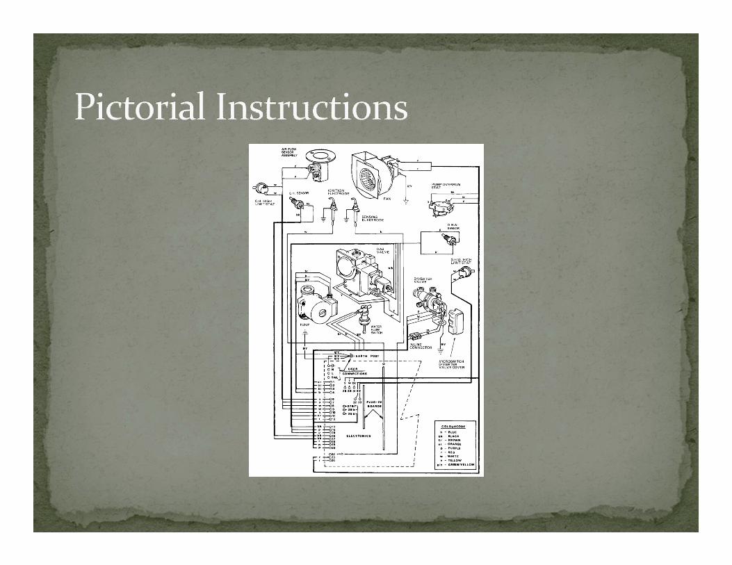
One line and Three line diagrams Schematics Wiring Diagrams Logic ladders Ancillary prints Pictorial instructions

One line diagram (1) One line diagrams will typically show in a simple fashion an over view of the station with simplified protection schemes displayed
Relay types, CT location, Remote tripping, and future breaker positions may also be displayed
Location of disconnect switches and grounding devices may be displayed
Demarcation between two entities may be displayed on one line diagram
Sometimes called Meter‐Relay one line


Three line diagram (2) Three line diagrams show all three phases in three phase applications
More detailed representation of AC current flow from source to bus to CT to end device
Both AC current and AC voltage three phase circuits may be represented
Disconnect switches, transfer buses, and grounding devices may be displayed
Great for proving phasing throughout a three phase system

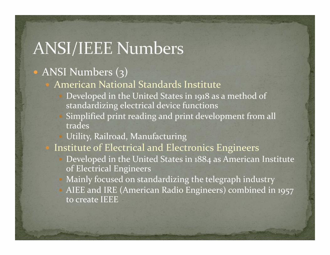
ANSI Numbers (3) American National Standards Institute
Developed in the United States in 1918 as a method of standardizing electrical device functions
Simplified print reading and print development from all trades
Utility, Railroad, Manufacturing Institute of Electrical and Electronics Engineers
Developed in the United States in 1884 as American Institute of Electrical Engineers
Mainly focused on standardizing the telegraph industry AIEE and IRE (American Radio Engineers) combined in 1957 to create IEEE


Symbol Legend (4) Symbol Legends are used to help identify devices on prints
Contacts, resistors, capacitors, disconnecting devices ANSI/IEEE numbers used on the print may be displayed
Title Block (4) Drawing number, Revision number, Sheet number Work order number Clear description of print classification Engineers name…..but no phone number….


Print Reference list (5) Quickly identify all associated prints
Contact/Input Use Chart(5) Used to quickly determine the intended use of an input or output contact associated with relays that have multiple inputs and outputs
Communication protocol usage and port set up may also be included


Contact development schedule (6) Identifies contact position in contact multiplying devices in both states, activated (on) and relaxed (off)
Lock out relays Control handles Reclose ON/OFF switches Transfer Trip ON/OFF switches Supervisory control cut out switches


Schematics Schematics are generally drawn with the following assumptions: Control circuits are de‐energized Contactors are relaxed Devices, such as lock out relays, are reset Stored energy has been removed Circuit breaker springs are relaxed Hydraulic/ Pneumatic energy dissipated
Insolation medium, SF6 gas or mineral oil has been removed Circuit breaker open and de‐energized, Transformer de‐energized

Schematics present the electrical operation of the device(s) that are represented on the print
AC schematic (7) Present the electrical operation of AC current and AC voltage of the device(s) represented on the print
DC schematic (8,9,10) Present the electrical operation of DC current and DC voltage of the device (s) represented on the print
ITS HOW IT WORKS!

Wiring Diagrams present a wiring method to complete the circuits as designed on the schematic Field device (11)
The field device wiring diagram shows the location of each terminal strip in relation to where it actually exists within the device
Control house (12) The control hose wiring diagram shows connections made from field devices also using nomenclature
Control Panel (13,14,15) The control panel wiring print has point to point style wiring method and also shows general location of panel devices

Logic Ladder (16,18) Logic Ladders are used to explain complicated sequences that are interdependent to complete an operation
Used in conjunction with a schematic to troubleshoot Capacitor schemes, Auto sectionalizing/ restoration schemes
Distributed Automation

Ancillary Prints (20,21) Provide additional details that may make understanding a scheme or circuit easier
Communication devices Communication connections IRIG or Clock signal connections Print index Panel layout Substation control house layout Manufacturer's drawings

Use of notes Always read the notes! Use of special conductor size Use of special lugs/connections Instructions on departmental responsibilities Special fusing instructions Device location notes Communication instructions

Feeling Gassy After energizing the alarm circuits for a new gas breaker, you notice the low gas alarm is in solid….but the breaker is full of gas and the gauge shows normal? What prints would help me get to the bottom of this issue?

Feeling Gassy After energizing the alarm circuits for a new gas breaker, you notice the low gas alarm is in solid….but the breaker is full of gas and the gauge shows normal? What prints would help me get to the bottom of this issue?
DC schematic (Control and SCADA) Wiring diagram for yard apparatus Factory drawings
What considerations are necessary for this repair?

I can’t hear what chur sayin When commissioning a new line protection relay, you notice that the relay is not indicating a change of state of the reclose ON/OFF switch What prints would I need to solve this problem?

I can’t hear what chur sayin When commissioning a new line protection relay, you notice that the relay is not indicating a change of state of the reclose ON/OFF switch What prints would I need to solve this problem?
Contact schedule Wiring diagram DC schematic I/O usage chart
What are some possible causes of this happening?

Off Kilter Upon energizing a new 12Kv breaker you notice the ammeter reads: A phase 110 amps B phase 118 amps C phase 140 amps N 224 amps
CT ratio 1200:5/240:1 Phase angle meter reads:
A phase 0.45 amps @0 degrees B phase 0.49 amps @ 240 degrees C phase 0.58 amps @ 300 degrees N 0.93 amps @ 285 degrees

Off Kilter continued What could possibly be the trouble? Quick calculation shows the phase angle readings should be: A phase 0.45 amps @ 0 degrees B phase 0.49 amps @ 240 degrees C phase 0.58 amps @ 120 degrees N 0.11 amps @ 6 degrees
What is the issue?

Off Kilter continued What could possibly be the trouble? Quick calculation shows the phase angle readings should be: A phase 0.45 amps @ 0 degrees B phase 0.49 amps @ 240 degrees C phase 0.58 amps @ 120 degrees N 0.11 amps @ 6 degrees
What is the issue? C phase current circuit is 180 degrees out of phase, the circuit is rolled somewhere

Off Kilter continued What prints would I need to help me correct this issue?
What considerations should I have before making this repair?

Off Kilter continued What prints would I need to help me correct this issue?
AC schematic DC schematic Wiring diagram (yard apparatus and control panel)
What considerations should I have before making this repair?


![XHTML-Print/CSS Print Profile Guidelines for PrintEnhanced:1 · 140 • XHTML-Print /CSS-Print Usage Guidelines 141 • Guidelines on how XHTML-Print[XHTML-PRINT] and CSS Print Profile](https://img.pdfslide.tips/doc/110x75/5f0eaedb7e708231d4406c47/xhtml-printcss-print-profile-guidelines-for-printenhanced1-140-a-xhtml-print.jpg)


![PPT Journal Reading.pptx [Autosaved]](https://img.pdfslide.tips/doc/110x75/55cf92dd550346f57b9a23fc/ppt-journal-readingpptx-autosaved.jpg)