Embed Size (px)
Citation preview

Introduction to
VHDL
Professor Gregory Moss Electrical & Computer Engineering Technology
Purdue University
1

VHDL VHSIC Hardware Description Language
(Very High Speed Integrated Circuit)
IEEE Standard 1076-1993 (& others)
concurrent language ⇒ circuit description documentation → simulation → synthesis
describes a model for a digital device
• gate ⇔ system • specify external view & internal view
↓ ↓ interface body
input/output ports functionality entity architecture
2
3
OUTPUTS
B.O.L.
Entity & Architecture
B.O.L. = “Blob Of Logic”
INPUTS
4
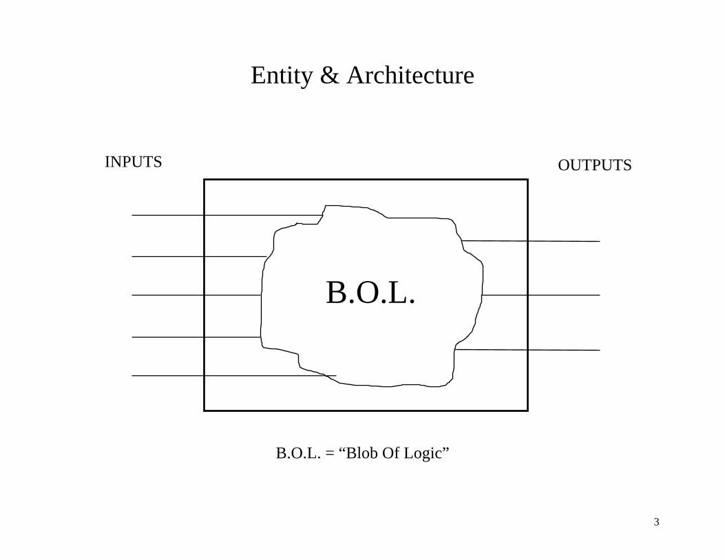
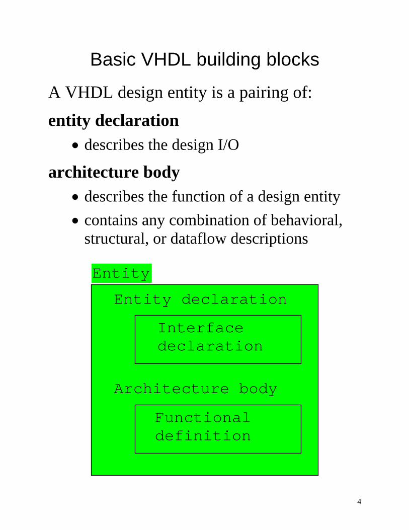
Basic VHDL building blocks
A VHDL design entity is a pairing of: entity declaration
• describes the design I/O
architecture body • describes the function of a design entity • contains any combination of behavioral,
structural, or dataflow descriptions
Architecture body
Functional definition
Entity
Entity declaration
Interface declaration
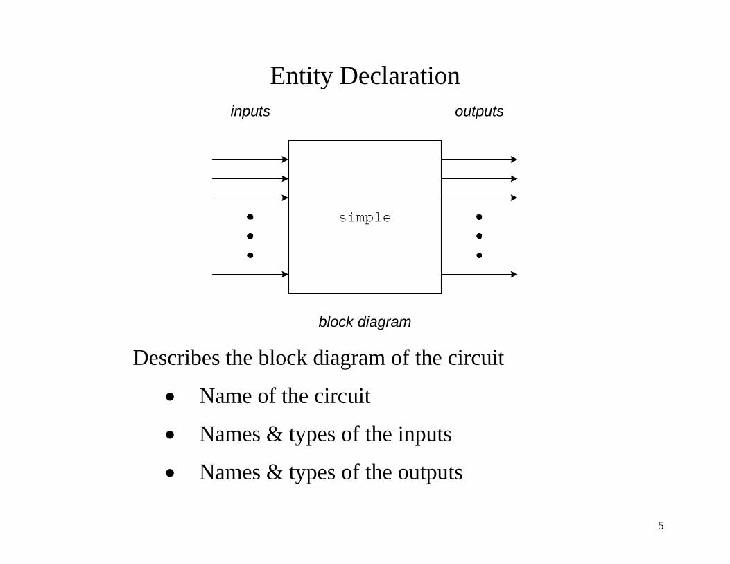
Entity Declaration inputs outputs
block diagram
simple
Describes the block diagram of the circuit
• Name of the circuit
• Names & types of the inputs
• Names & types of the outputs
5

Architecture Body
B
A
C
DE
X
Y
Z
Use statements to describe the circuit functionality
6

ENTITY simple IS PORT (
a, b, c, d, e :IN BIT;
x, y, z :OUT BIT);
END simple;
ARCHITECTURE example OF simple IS
BEGIN
-- signal assignment statements (Boolean)
x <= (a OR c) AND NOT b;
y <= (a AND b) OR (NOT a AND c);
z <= d OR e;
END example;
7

Concurrent vs. Sequential Statements
8

Concurrent Statements • execute at same time – in parallel
• order independent
• execute outside of a process
Sequential Statements • execute one at a time – in sequence
• order dependent
• execute inside a process
• IF, CASE, FOR LOOP
9

2-input Decoder
10
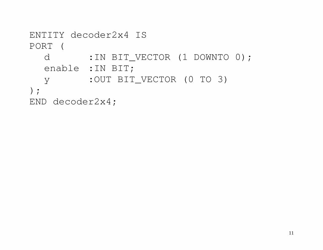
ENTITY decoder2x4 IS PORT ( d :IN BIT_VECTOR (1 DOWNTO 0); enable :IN BIT; y :OUT BIT_VECTOR (0 TO 3) ); END decoder2x4;
11
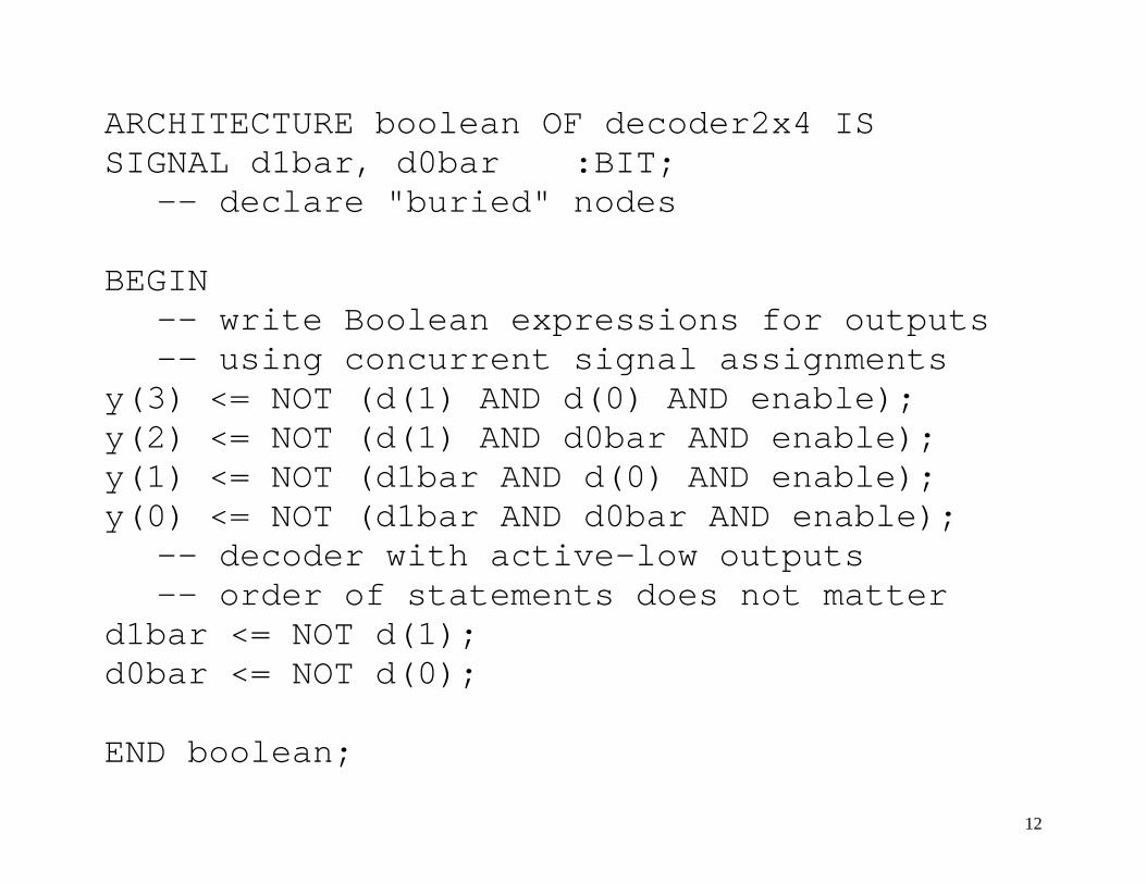
ARCHITECTURE boolean OF decoder2x4 IS SIGNAL d1bar, d0bar :BIT;
-- declare "buried" nodes BEGIN
-- write Boolean expressions for outputs -- using concurrent signal assignments
y(3) <= NOT (d(1) AND d(0) AND enable); y(2) <= NOT (d(1) AND d0bar AND enable); y(1) <= NOT (d1bar AND d(0) AND enable); y(0) <= NOT (d1bar AND d0bar AND enable);
-- decoder with active-low outputs -- order of statements does not matter
d1bar <= NOT d(1); d0bar <= NOT d(0); END boolean;
12
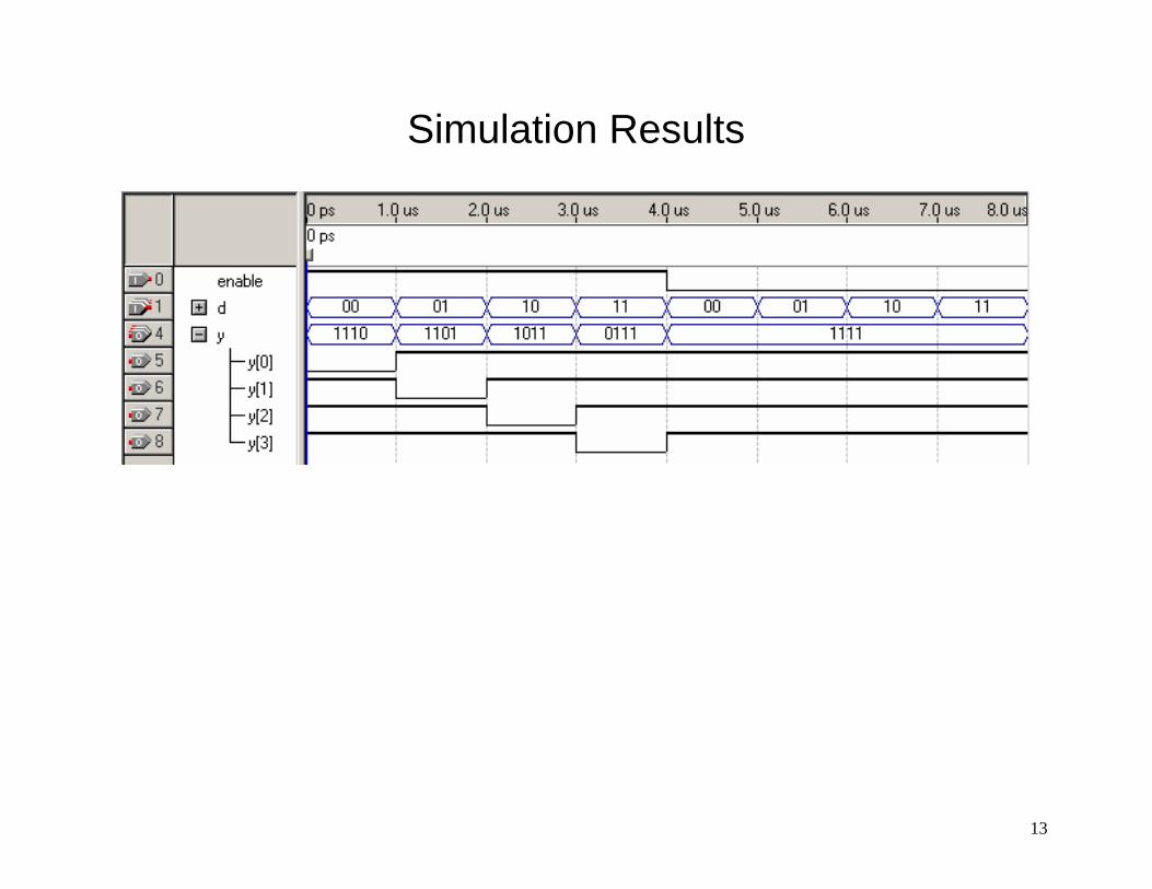
Simulation Results
13
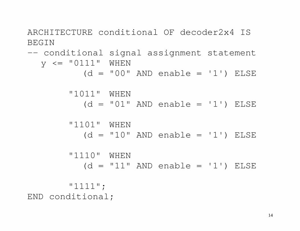
ARCHITECTURE conditional OF decoder2x4 IS BEGIN -- conditional signal assignment statement y <= "0111" WHEN
(d = "00" AND enable = '1') ELSE "1011" WHEN
(d = "01" AND enable = '1') ELSE "1101" WHEN
(d = "10" AND enable = '1') ELSE "1110" WHEN
(d = "11" AND enable = '1') ELSE "1111"; END conditional;
14

ARCHITECTURE selected OF decoder2x4 IS SIGNAL inputs :BIT_VECTOR (2 DOWNTO 0);
-- define new 3-bit signal array -- “buried” within entity
BEGIN inputs <= enable & d; -- concatenate bits together for new array -- selected signal assignment statement WITH inputs SELECT y <= "0111" WHEN "100", "1011" WHEN "101", "1101" WHEN "110", "1110" WHEN "111", "1111" WHEN OTHERS; -- default END selected;
15
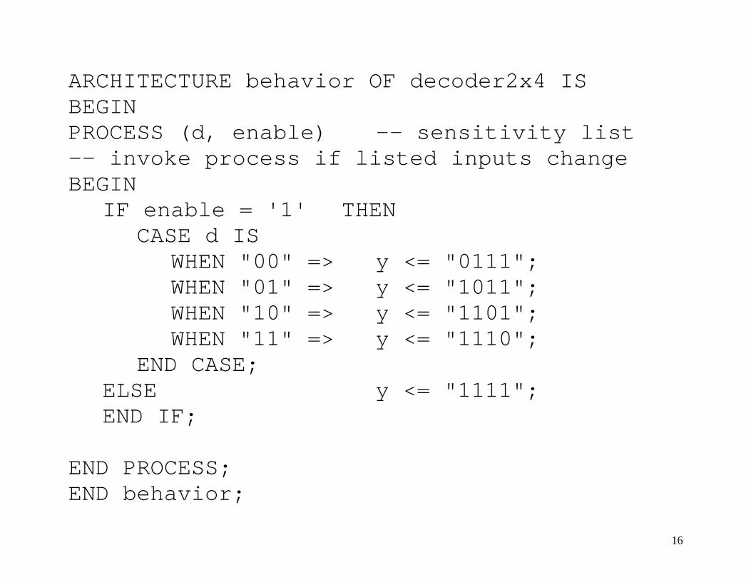
ARCHITECTURE behavior OF decoder2x4 IS BEGIN PROCESS (d, enable) -- sensitivity list -- invoke process if listed inputs change BEGIN IF enable = '1' THEN CASE d IS WHEN "00" => y <= "0111"; WHEN "01" => y <= "1011"; WHEN "10" => y <= "1101"; WHEN "11" => y <= "1110"; END CASE; ELSE y <= "1111"; END IF; END PROCESS; END behavior;
16

Ports
I/O signals in an entity declaration
port declaration → set of ports defined for an entity
each port must have: name (identifier) direction (mode)
[in, out, buffer, inout] data type
[bit, bit_vector, integer, Boolean, std_logic, std_logic_vector, enumerated]
17
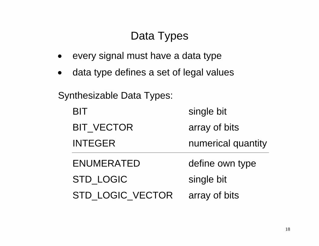
Data Types
• every signal must have a data type
• data type defines a set of legal values
Synthesizable Data Types: BIT single bit BIT_VECTOR array of bits INTEGER numerical quantity
ENUMERATED define own type STD_LOGIC single bit STD_LOGIC_VECTOR array of bits
18
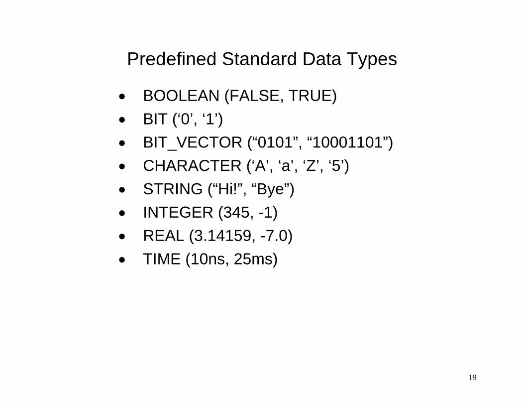
Predefined Standard Data Types
• BOOLEAN (FALSE, TRUE) • BIT (‘0’, ‘1’) • BIT_VECTOR (“0101”, “10001101”) • CHARACTER (‘A’, ‘a’, ‘Z’, ‘5’) • STRING (“Hi!”, “Bye”) • INTEGER (345, -1) • REAL (3.14159, -7.0) • TIME (10ns, 25ms)
19

Array • collection of objects (each one is the same type)
• two standard types: bit vector & string
• do not represent a numerical value
• range is defined when array is declared using “to” or “downto”
• direction of a “slice” of an array must match the direction in which array is declared
• arrays are assigned to each other by matching their position within the array
• single bits and vectors can be concatenated together (using “&” operator)
20

VHDL Example signal Data types assignment statement
BIT sig1 <= ‘1’;
BIT_VECTOR arrayx <= “1011”;
INTEGER count <= count + 1;
ENUMERATED mytype <= idle;
To make an assignment to a signal, the data types on either side of the signal assignment operator must be the same
21
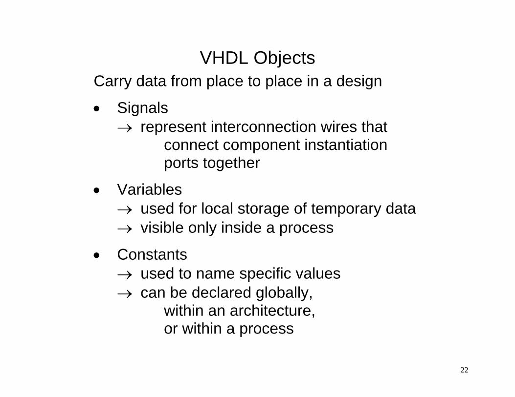
VHDL Objects Carry data from place to place in a design
• Signals → represent interconnection wires that connect component instantiation ports together
• Variables → used for local storage of temporary data → visible only inside a process
• Constants → used to name specific values → can be declared globally, within an architecture, or within a process
22
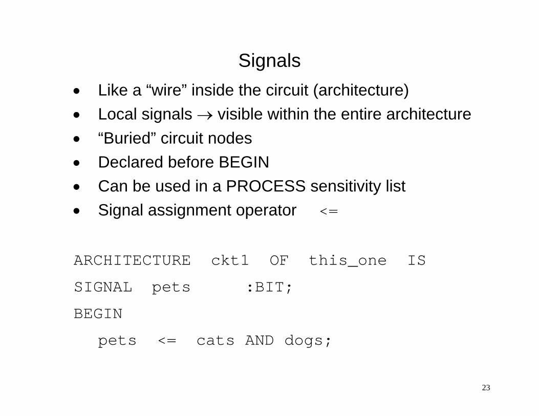
Signals • Like a “wire” inside the circuit (architecture) • Local signals → visible within the entire architecture • “Buried” circuit nodes • Declared before BEGIN • Can be used in a PROCESS sensitivity list • Signal assignment operator <=
ARCHITECTURE ckt1 OF this_one IS
SIGNAL pets :BIT;
BEGIN
pets <= cats AND dogs;
23

Variables • Local storage of temporary data
• Only declared inside of a PROCESS
• Only visible inside the PROCESS
• Variable assignment operator := ARCHITECTURE ckt2 OF that_one IS BEGIN PROCESS (a, b) VARIABLE f1 :BIT; BEGIN f1 := NOT a AND b;
24

Process • Contains sequential statements (IF, CASE)
• Does not execute continuously
• “Invoked” by an “event” on a signal in the “sensitivity list”
• Statements are executed in sequence when a change occurs in a signal in the sensitivity list
• Outputs are “updated” when a process “suspends” at “END PROCESS”
• Multiple processes interact concurrently
25

Design Units Smallest item in VHDL that you can compile:
• entity • architecture • configuration • package • package body
contains body (algorithm) of procedures or functions for a package
VHDL design file is compiled into a “library” storage area referenced as “work”
26

Package contains a collection of definitions that may be referenced by many designs at the same time
• global signals
• constant values
• user defined data types
• component declarations
• subprograms of VHDL code shared between different designs → Package Body
27
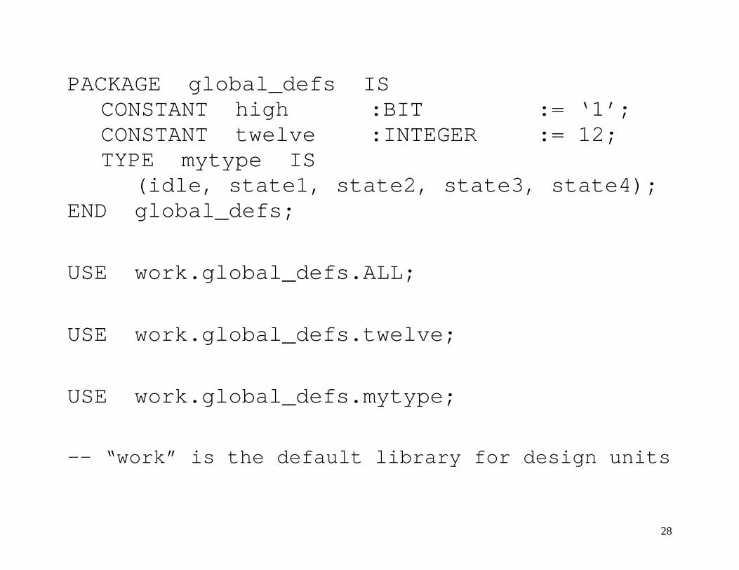
PACKAGE global_defs IS CONSTANT high :BIT := ‘1’; CONSTANT twelve :INTEGER := 12; TYPE mytype IS
(idle, state1, state2, state3, state4); END global_defs;
USE work.global_defs.ALL;
USE work.global_defs.twelve;
USE work.global_defs.mytype;
-- “work” is the default library for design units
28
Library Library statement loads library so contents are available when compiling a source file Use statement makes contents of specified library (packages or other design units) visible to design units in the current source file If you only use work library, then you just need to specify use statement
29

LIBRARY ieee; USE IEEE.STD_LOGIC_1164.ALL;
-- to process “standard logic” types, their -- declarations must be made visible to the -- entity by way of library and use clauses ENTITY example IS PORT (
a,b :IN STD_LOGIC; c :IN STD_LOGIC_VECTOR (3 DOWNTO 0); z :OUT STD_LOGIC
); END example;
30

Standard Logic – IEEE Standard 1164 Defines Multi-Value Logic (MVL)
Provides powerful simulation & debugging tool for designers
U uninitialized X unknown ⎫ 0 logic 0 ⎬ strong drive 1 logic 1 ⎭ Z high impedance W unknown ⎫ L logic 0 ⎬ weak drive H logic 1 ⎭ - don’t care
31
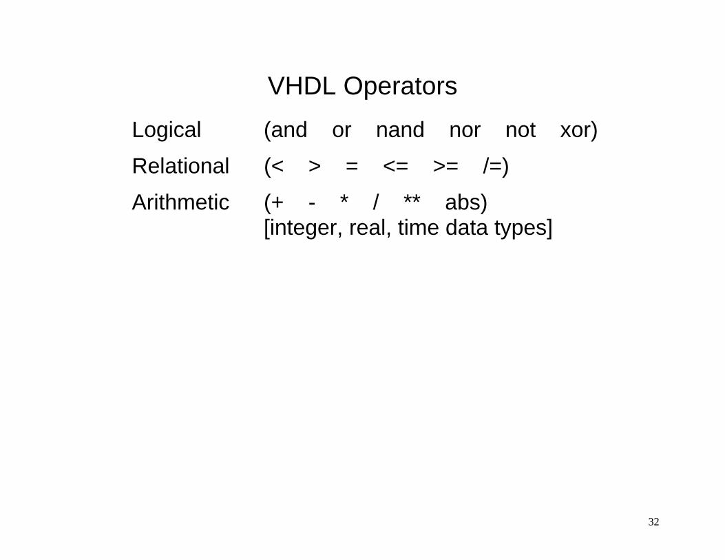
VHDL Operators Logical (and or nand nor not xor) Relational (< > = <= >= /=) Arithmetic (+ - * / ** abs)
[integer, real, time data types]
32

33
entity entity-name is port (list-of-interface-ports);
end entity-name; -- this is a comment line architecture architecture-name of entity-name is
[architecture-item-declarations] begin
concurrent-statements: process-statement block-statement concurrent-procedure-call-statement concurrent-assertion-statement concurrent-signal-assignment-statement component-instantiation-statement generate-statement
end architecture-name ;
34
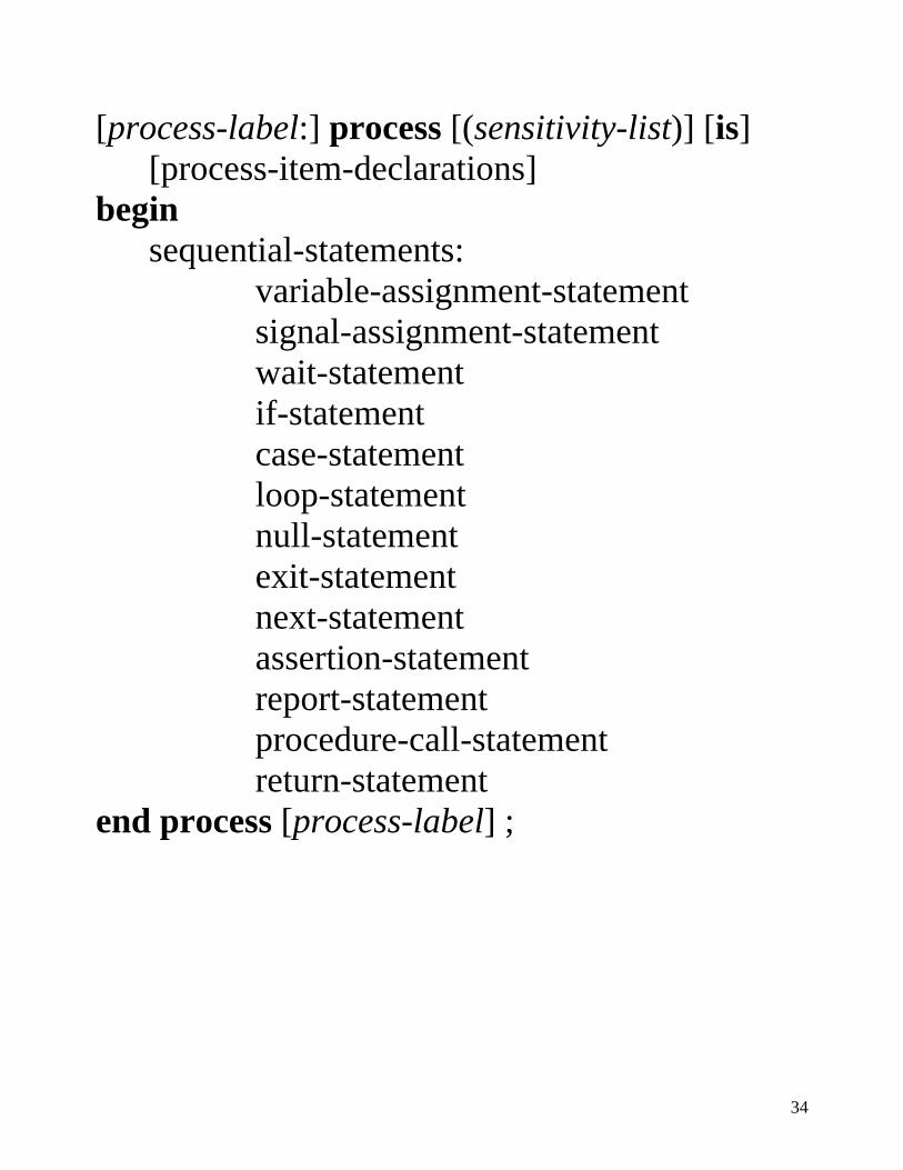
[process-label:] process [(sensitivity-list)] [is] [process-item-declarations]
begin sequential-statements:
variable-assignment-statement signal-assignment-statement wait-statement if-statement case-statement loop-statement null-statement exit-statement next-statement assertion-statement report-statement procedure-call-statement return-statement
end process [process-label] ;
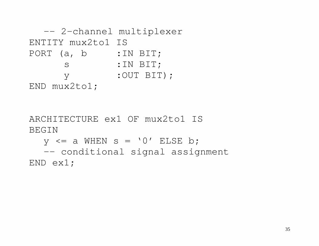
-- 2-channel multiplexer ENTITY mux2to1 IS PORT (a, b :IN BIT;
s :IN BIT; y :OUT BIT); END mux2to1; ARCHITECTURE ex1 OF mux2to1 IS BEGIN y <= a WHEN s = ‘0’ ELSE b; -- conditional signal assignment END ex1;
35

ARCHITECTURE ex2 OF mux2to1 IS BEGIN PROCESS (a, b, s) BEGIN
IF s = ‘0’ THEN y <= a; -- IF statement ELSE y <= b; END IF;
END PROCESS; END ex2; -- 2-channel, 4-bit multiplexer ENTITY mux2to1 IS PORT (a, b :IN BIT_VECTOR (3 DOWNTO 0);
s :IN BIT; y :OUT BIT_VECTOR (3 DOWNTO 0)); END mux2to1;
36

ENTITY mux4to1 IS -- 4-channel, 4-bit MUX PORT (a, b :IN BIT_VECTOR (3 DOWNTO 0);
c, d :IN BIT_VECTOR (3 DOWNTO 0); s :IN BIT_VECTOR (1 DOWNTO 0);
y :OUT BIT_VECTOR (3 DOWNTO 0)); END mux4to1; ARCHITECTURE ex3 OF mux4to1 IS BEGIN PROCESS (a, b, c, d, s) BEGIN
CASE s IS WHEN “00” => y <= a; WHEN “01” => y <= b; WHEN “10” => y <= c; WHEN “11” => y <= d;
END CASE; END PROCESS; END ex3; 37

4-channel, 4-bit MUX Simulation
38
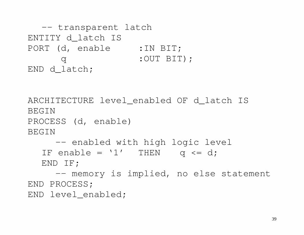
-- transparent latch ENTITY d_latch IS PORT (d, enable :IN BIT; q :OUT BIT); END d_latch; ARCHITECTURE level_enabled OF d_latch IS BEGIN PROCESS (d, enable) BEGIN
-- enabled with high logic level IF enable = ‘1’ THEN q <= d; END IF;
-- memory is implied, no else statement END PROCESS; END level_enabled;
39

-- clocked D flip-flop ENTITY dflipflop IS PORT (d, clock :IN BIT; q :OUT BIT); END dflipflop; ARCHITECTURE edge_triggered OF dflipflop IS BEGIN PROCESS (clock) BEGIN
-- triggers on rising edge IF (clock = ‘1’ AND clock’EVENT) THEN q <= d; END IF;
-- ’EVENT signal attribute END PROCESS; END edge_triggered;
40
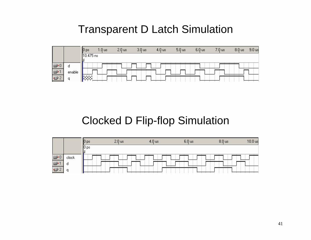
Transparent D Latch Simulation
Clocked D Flip-flop Simulation
41

LIBRARY ieee; USE ieee.std_logic_1164.all; -- using Standard Logic ENTITY dflipflop IS PORT (d, clock :IN STD_LOGIC; q :OUT STD_LOGIC); END dflipflop; ARCHITECTURE edge_trig OF dflipflop IS BEGIN PROCESS (clock) BEGIN IF (RISING_EDGE(clock)) THEN q <= d;
-- also FALLING_EDGE() detection END IF; END PROCESS; END edge_trig;
42

ENTITY d_ff IS PORT (data, clock, preset, clear :IN BIT;
q_out :OUT BIT); END d_ff; ARCHITECTURE asynchronous OF d_ff IS BEGIN PROCESS (clock, preset, clear) BEGIN -- priority order: clear, preset, clock IF (clear = '0') THEN q_out <= '0'; ELSIF (preset = '0') THEN q_out <= '1'; ELSIF (clock'EVENT AND clock = '0') THEN q_out <= data; END IF; END PROCESS; END asynchronous;
43
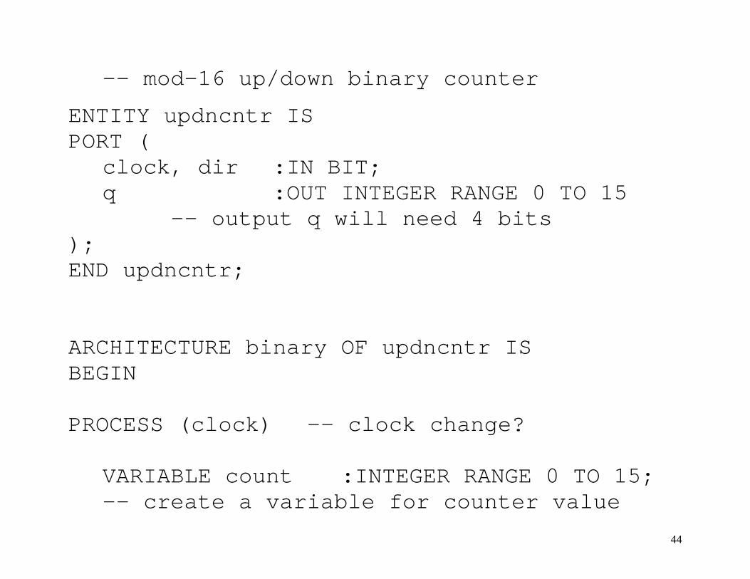
-- mod-16 up/down binary counter
ENTITY updncntr IS PORT ( clock, dir :IN BIT; q :OUT INTEGER RANGE 0 TO 15 -- output q will need 4 bits ); END updncntr; ARCHITECTURE binary OF updncntr IS BEGIN PROCESS (clock) -- clock change?
VARIABLE count :INTEGER RANGE 0 TO 15; -- create a variable for counter value
44
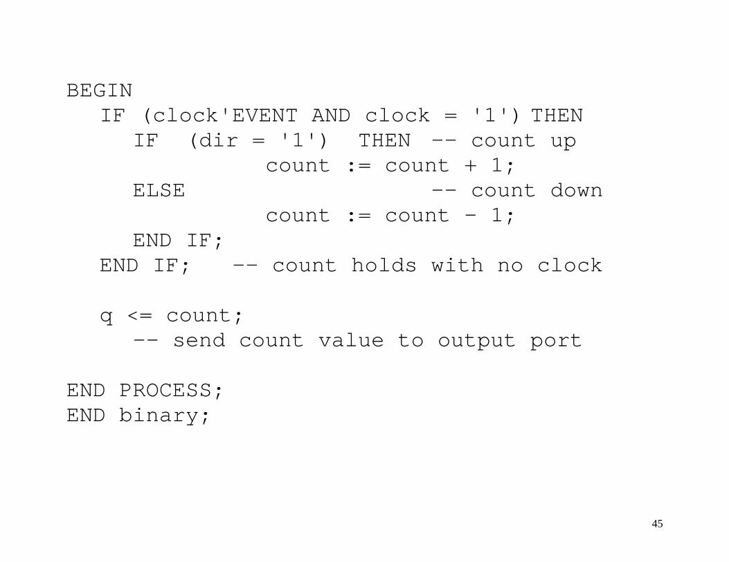
BEGIN IF (clock'EVENT AND clock = '1') THEN IF (dir = '1') THEN -- count up count := count + 1; ELSE -- count down count := count - 1; END IF; END IF; -- count holds with no clock q <= count;
-- send count value to output port
END PROCESS; END binary;
45

Mod-16 Up/Down Binary Counter Simulation
46

ENTITY mod10 IS PORT ( clock, enable :IN BIT;
load, clear :IN BIT; d :IN INTEGER RANGE 0 TO 15; q :OUT INTEGER RANGE 0 TO 15; rco :OUT BIT ); END mod10; ARCHITECTURE bcd OF mod10 IS BEGIN PROCESS (clock, clear, enable) -- asynchronous clear VARIABLE counter :INTEGER RANGE 0 TO 15; BEGIN
47
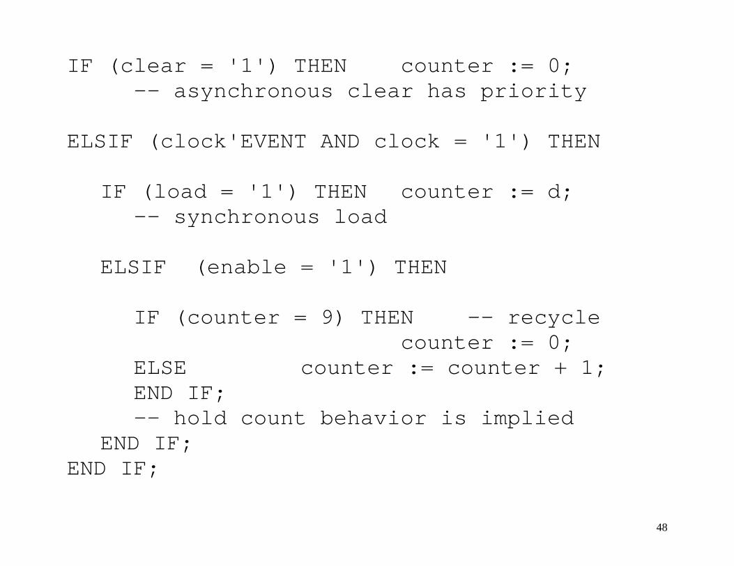
IF (clear = '1') THEN counter := 0; -- asynchronous clear has priority ELSIF (clock'EVENT AND clock = '1') THEN IF (load = '1') THEN counter := d; -- synchronous load ELSIF (enable = '1') THEN IF (counter = 9) THEN -- recycle counter := 0; ELSE counter := counter + 1; END IF; -- hold count behavior is implied END IF; END IF;
48

-- rco detects terminal count when enabled IF ((counter = 9) AND (enable = '1')) THEN rco <= '1'; ELSE rco <= '0'; END IF; q <= counter; -- output counter to ports END PROCESS; END bcd;
49
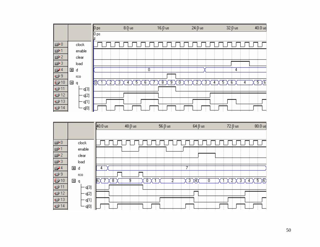
50