Embed Size (px)
Citation preview

Presentation Identifier (Title or Location), Month 00, 2008
Issues in Chemical Looping Combustion2006 NETL Multiphase Workshop
April 22-23, 2009
Thomas J. O’Brien, Chemist
CO2 + H2O
Ash
RECYCLECO2 + H2O
Fuel
Air
Seal
Seal
N2 + O2
(vitiated air)
2
Outline
• Backstory
• Description of Chemical Looping Combustion (CLC)
• Advantages/Disadvantages of the Technology
• History of the development of CLC
• Status of the technology
• CLC of solid fuels

3
Perspective
• US coal-fired power plants (~40% of US power)~1,015 million tons of coal in 2009, (~1,042 million tons in 2008, < 2.3%)~10 million coal car loads (100 tons/car load)~100,000 trains (100 cars/train) ~275 trains/day
C + O2 → CO212 + 32 = 44

4
Atmospheric CO2 Overview
• Atmospheric CO2(Global Temp Change; Sea Level Rise – thermal expansion only)
284 ppm - pre-industrial level
380 ppm – current(ΔT= 1 ºC/1.8 ºF)
450 ppm – 2100 (+ ΔT= 0.6 ºC/1 ºF; ΔHsea level = 14 cm/ 5.5 in )
U.S. Climate Change Science Program “an attainable target if the world quickly adapts conservation practices and new green technologies to cut emissions dramatically.”
750 ppm - 2100 with current trends (+ ΔT= 2.2 ºC/4 ºF; ΔHsea level = 22 cm/ 8.7 in )
Washington, et al., “How Much Climate Change Can Be Avoided by Mitigation?”Geophysical Research Letters, (in press, 2009)
http://news.bbc.co.uk/April 15,2009

5
EPA Endangerment Finding(4/17/2009)
Impacts that EPA believes may be significant for US citizens:
• an increased risk of droughts and floods
• sea level rise
• more intense storms and heat waves
• harm to water supplies, agriculture and wildlife
EPA - The science supporting the proposed endangerment finding was “compelling and overwhelming.”
» E.P.A. began the process of regulating 5 green-house gases (climate-altering substances) under the Clean Air Act «

6
Options to Reduce CO2 Emission
• Conservation - modify life style and economy to reduce energy intensity
• Efficiency - increase efficiency of fuel conversion and utilization
• Fuel switching - Increase non-fossil fuel based power production– Solar– Nuclear– Biomass– Wind-power– Tidal– Geo-thermal– Hydro
• Fossil Fuels with Carbon Capture and Sequestration – Separation (75% of energy penalty ; 100-200 $/ton C)
• Post-combustion• Oxy-fired• Pre-combustion• Un-mixed combustion
– Compression & storage (25% of energy penalty; 4-8 $/ton C)
The Magenn Power Air Rotor Systemhttp://www.magenn.com/technology.php

7
Schematic of a Chemical Looping Combustor
Combustion ProductsCO2 , H2O
Depleted AirO2 , N2
FuelCnHm
AirO2 , N2
MeO
Me
Air Reactor
Fuel Reactor

8
Generic CLC Reactions
Fuel Reactor (FR) – endothermic (usually) (ΔHFR > 0)
CnH2m + (2n+m) MeO → (2n+m) Me + m H2O + n CO2(CH4 + 4 NiO → 4 Ni + 2 H2O + CO2)
Air Reactor (AR) – highly exothermic (ΔHAR << 0)
2 Me + O2 → 2 MeO(2 Ni + O2 → 2 NiO)
Net Reaction – highly exothermic (ΔHFR ≡ ΔHFR + ΔHAR)
CnH2m + O2 → m H2O + n CO2(CH4 + O2 → 2 H2O + CO2)

9
Chemical Looping Combustion Process(gaseous fuel)
CO2 + H2O
Fuel
Air
Seal
Seal
N2 + O2
(vitiated air)Air reactor – carrier is oxidized by air; heat is released
Cyclone – hot oxidized carrier is sent to fuel reactor; hot vitiated air is used for power generation
Fuel reactor – carrier oxidizes fuel to CO2 and H2O (usually endothermic); reduced carrier is returned to the air reactor (without any fuel).
Lyngfelt, et al., 2001

10
CO2 + H2O
Ash
RECYCLE
CO2 + H2OFuel
Air
Seal
Seal
N2 + O2
(vitiated air)
Chemical Looping Combustion Process(solid fuel)
Ash may be elutriated from the fuel reactor
Recycle gas must be used to fluid the fuel reactor, along with self fluidization due to chemistry
Recycle gas must “burn out”the char

11
Advantages of CLC Technology
1) Produces separate CO2/H2O gas streamNo cost of separationSeparation of H2O on cooling/compressionCO2 stream at process pressureCould contain CO, H2, unburned fuel, SO2, fuel-N, Hg, …
2) No/Low NOxNo thermal or prompt NOx (low T of Air Reactor)No “hot-spots” (fluidized bed processes)(Low temperature) fuel NOx … not determined (???)
3) Compatible with S-capture technologies
12
Advantages of CLC Technology (cont.)
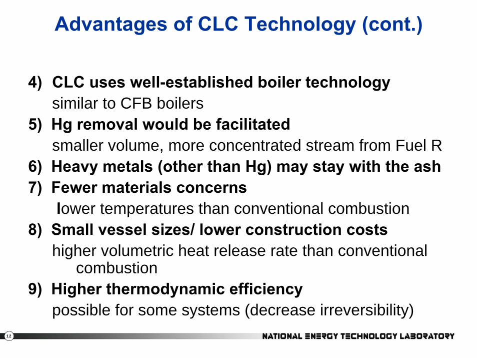
4) CLC uses well-established boiler technologysimilar to CFB boilers
5) Hg removal would be facilitatedsmaller volume, more concentrated stream from Fuel R
6) Heavy metals (other than Hg) may stay with the ash7) Fewer materials concerns
lower temperatures than conventional combustion8) Small vessel sizes/ lower construction costs
higher volumetric heat release rate than conventional combustion
9) Higher thermodynamic efficiencypossible for some systems (decrease irreversibility)

13
Disadvantages of CLC Technology
1) Carrier circulationSolids handlingNon-mechanical valves
2) Dual reactors
3) Lower exhaust gas temperature (~1000 ºC)/pressureDifficult to couple to a gas turbine – loss in efficiency

14
Overview – CLC Testing History
1980
1990
2000
2010
Richter and Knochethermodynamic efficiency
(1983 – in English)
Ishida et al (1987) -efficiencyIshida and Jin (1996) – no (thermal) NOxseparation
Mattisson et al. (2001) – Fixed bed iron-oxide/methane experiments
10 kW CLC (2003) – Chalmers, Alstom, CSIC/ICB, TU of Vienna
2nd Gen. 10 kW CLC using Cu-based carrier – CSIC/ICB. De Diego et al (2007)
Gaseous Fuels
Leion et. al (2008) – Solid fuel, batch Rx Berguerand and Lyngfelt (2008 a&b) – 10kW
CLOU Concept
Mattison et. al (2009) – Cu-carrier w PetcokeShen et. al (2009) – NiO carrier & coal
Ref: Anthony (2008) Ind. Eng. Chem res
Lyngfelt and Mattisson (2005)– Swedish Patent CLOU
Lewis and GillilandCO2 production
(1954)
Richter and Knochethermodynamic efficiency
(1968 – in German)
1950
1960
1970
Anheden, Näsholm &Svedberg (1995)efficiency & CO2 separaiton

15
History of the development of CLC
1) Method to produce pure CO2Lewis and Gilliland (1954)
2) Proposed to improve combustion efficiency …reduce exergy
Richter und Knoche (1968); Ishida (1982)
1) Implications for carbon capture are recognized2) Chalmers program3) European program4) US effort

16
Criteria for Carriers(Ni-, Cu-, Fe-, … ; CaSO4/CaS)
• Chemical– High reactivity – oxidation and reduction rates– Multiple oxidation states – oxygen carrying capacity– Light weight– Complete conversion at (T,P)– No carbon deposition– Interaction with support & trace elements: S, N, Al, Si, Fe, Hg, K, Na, …
• Physical– Attrition– Agglomeration
• Economics– Raw materials (carrier + support)– Fabrication– Durability
• Environmental - Benign– CLC process– Extraction process

17
Bed of Fuel Reactor
• Fuel Reactor will have solid particles of different size and density.
– Carrier (Metal Oxide or CaSO4)
– Coal (Solid Fuel)
– Ash
– CaCO3 for SOx removal

18
Critical Issues in the Fuel Reactor(to be addressed by multi-phase CFD)
• Volatile fuel must be converted in the bedFuel, CO or H2 will escape the FR
• Additional compression costs• Returned to the FR (or used as syngas)
• Char burnoutComplete conversion
• Large residence time/reactor size• Tendency to move to the AR

19
Critical Issues between FR & AR(to be addressed by multi-phase CFD)
• Flow from FR to AR must not contain unburned fuelFuel combustion in the AR
• Additional heat release in the AR• CO2 released will escape capture
• Air flow must not leak into the FRN2 will contaminate the CO2/H20 stream
• Additional compression costs• Inerts would be eturned to the AR
• Char burnoutComplete conversion
• Large residence time/reactor size• Tendency to move to the AR

20
Process Design Issues
• Air Reactor: Me + ½ O2 → MeO– Transport reactor– In-bed heat removal
• Gas-Particle Separation after AR– Cyclone separator– Heat removal (air stream and/or solids stream)
• Fuel Reactor: solid fuel + MeO → Me + H2O + CO2– Bubbling bed/Moving bed
• Gas-Particle-Particle Separation after FR• Heat Removal• Non-mechanical Valve

21
Pilot Plant Studies
• 10 kWth scale• Chalmers University (Tobias Mattisson, Anders Lyngfelt)• 50 kWth scale
• Vienna University of Technology (Hermann Hofbauer)• 120 kWth scale
• Alstom: Coal-CaS/CaSO4 (Herb Andrus)– Phase II & III (<2009) 150 kWth
– Phase IV (>2009) 3 MWth
• Ohio State University: Coal-Fe2O3 (L.S. Fan)

22
Vienna University of Technologyhttp://www.chemical-looping.at/start.asp
•Gaseous fuel
•120 kWth scale

23
ALSTOM Power, Inc.(Heb Andrus)
• CaSO4/CaS carrier, formed from limestone• Coal fuel• 150 kWth PDU, building a 3 MWth PDU
24
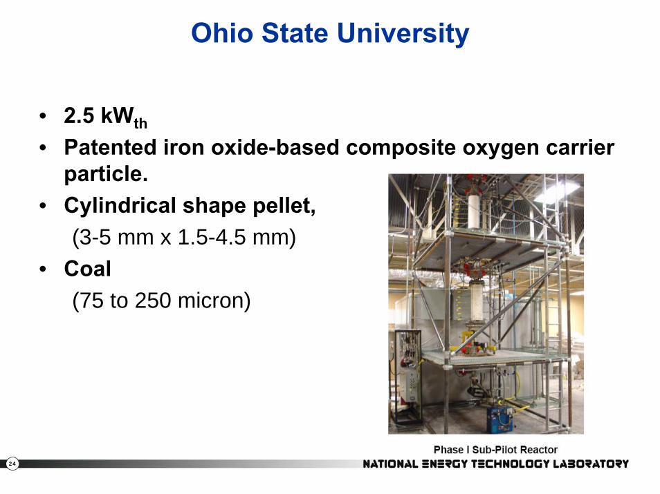
Ohio State University
• 2.5 kWth
• Patented iron oxide-based composite oxygen carrier particle.
• Cylindrical shape pellet, (3-5 mm x 1.5-4.5 mm)
• Coal (75 to 250 micron)

25
Simulation of Lab-Scale CLC of Petcoke(Leion et al., 2007)
Experimental ParametersTemperature 1223 K (950 °C)Pressure 1 atmCarrier Fe2O3
Fluidization Vel. 0.55 m/s~50 umf
Donskoi and McElwain (2001)
Carrier KineticsEverson GasificationNagpal (2005)Devolatilization
Chemical Kinetics
Leion, H., T. Mattisson and A. Lyngfelt, “The use of petroleum coke as fuel in chemical-looping
combustion,”Fuel 86, 1947–1958, 2007.
Thanks to …
Kartikeya Mahalatkar (ANSYS-Fluent)Dave Huckaby (NETL-DOE)John Kuhlman (NETL-WVU
26
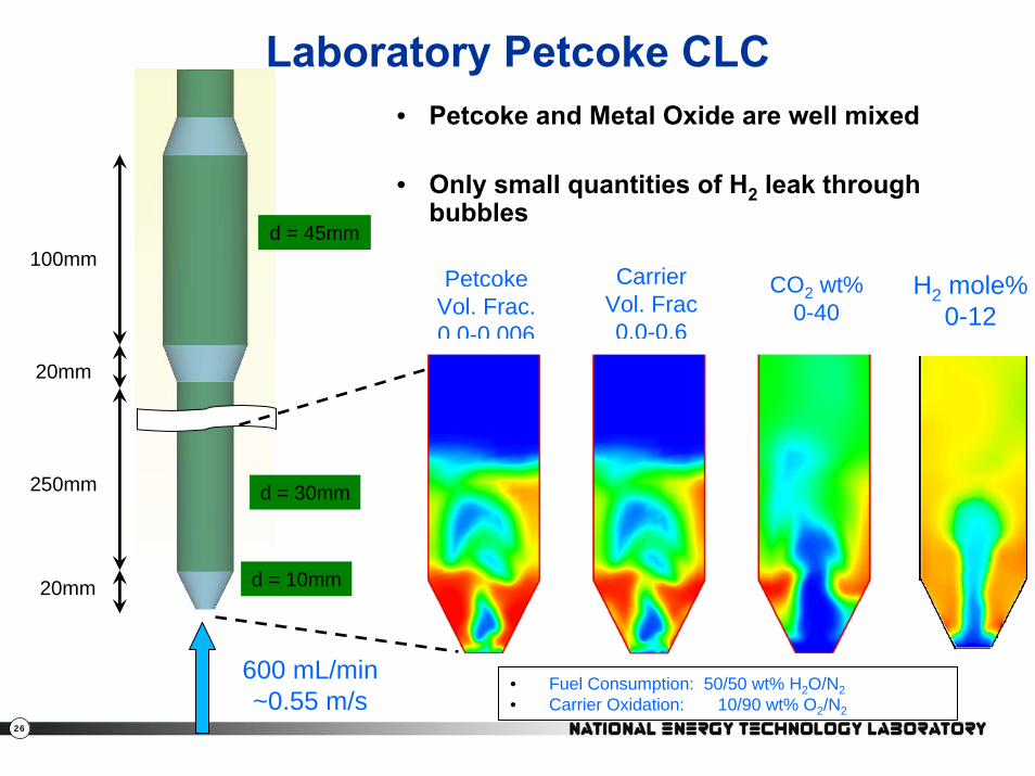
Laboratory Petcoke CLC
• Fuel Consumption: 50/50 wt% H2O/N2• Carrier Oxidation: 10/90 wt% O2/N2
600 mL/min ~0.55 m/s
d = 10mm
d = 30mm
d = 45mm
20mm
250mm
100mm
20mm
Carrier Vol. Frac0.0-0.6
PetcokeVol. Frac.0.0-0.006
CO2 wt%0-40
H2 mole%0-12
• Petcoke and Metal Oxide are well mixed
• Only small quantities of H2 leak through bubbles
27
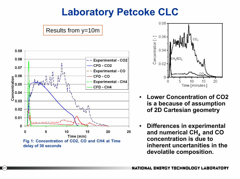
Laboratory Petcoke CLCResults from y=10m
Fig 1: Concentration of CO2, CO and CH4 at Time delay of 30 seconds
• Lower Concentration of CO2 is a because of assumption of 2D Cartesian geometry
• Differences in experimental and numerical CH4 and CO concentration is due to inherent uncertanities in the devolatile composition.

28
Thanks
E. David HuckabyKartikeya Mahalatkar
John Kuhlman