Embed Size (px)
Citation preview

1 di 38
Rev. 03 del 28/09/10
Istruzioni originali per la messa in servizio, l’uso e la manutenzione
Translation of the original instructions for installation, operation and maintenance
Návod pro instalaci, provoz a údržbu
Trasformatori a secco
Dry type transformers
Suché transformátory

2 di 38
Rev. 03 del 28/09/10
INDICE / INDEX / OBSAH
1. GENERALITÀ / OVERVIEW / VŠEOBECNĚ 3
2. TRASPORTO E MOVIMENTAZIONE / TRANSPORTATION AND MOVEMENT / PŘEPRAVA A MANIPULACE 4
3. RICEVIMENTO E IMMAGAZZINAGGIO / RECEPTION AND STORAGE / PŘEJÍMKA A SKLADOVÁNÍ 9
4. INSTALLAZIONE / INSTALLATION / INSTALACE 10
5. MESSA IN SERVIZIO / START-UP / UVEDENÍ DO PROVOZU 20
6. MANUTENZIONE / MAINTENANCE / ÚDRŽBA 28
7. MESSA FUORI SERVIZIO / SHUT-OFF / UVEDENÍ MIMO PROVOZ 33
8. I PROBLEMI PIU’ COMUNI / TROUBLE SHOOTING / NEJČASTĚJŠÍ PROBLÉMY 34
9. COMPATIBILITA’ ELETROMAGNETICA / ELECTROMAGNETIC COMPATIBILITY / ELEKTROMAGNETICKÁ KOMPATIBILITA 35
10. DEMOLIZIONE / DEMOLITION / LIKVIDACE 36
11. NOTE / NOTES / POZNÁMKY 37
12. CONCLUSIONE / CONCLUSION / ZÁVĚR 38
13. COME CONTATTARCI / HOW TO CONTACT US / KONTAKTUJTE NÁS 38
3 di 38
Rev. 03 del 28/09/10
1. GENERALITÀ / OVERVIEW / VŠEOBECNĚ
Grazie per aver scelto un trasformatore SEA. I trasformatori SEA sono progettati, costruiti e collaudati in accordo alle norme vigenti e con i più moderni standard di qualità. Il presente manuale contiene le informazioni necessarie per il trasporto, la messa in servizio e la manutenzione dei trasformatori da distribuzione.
Nel corso del manuale i trasformatori a secco verranno classificati in due tipi:
� Con avvolgimenti inglobati in resina (“Trasformatori in resina”);
� Con avvolgimenti non inglobati, tipicamente in classe H (“Trasformatori in aria”).
Alcuni accessori descritti nel manuale potrebbero non essere montati nel Vostro trasformatore. Consultate sempre la documentazione tecnica in Vostro possesso e/o la bolla di consegna per verificare la lista di accessori effettivamente presenti.
Condizioni di Garanzia
Tutti i trasformatori SEA sono garantiti contro tutti i difetti di fabbricazione per un anno dalla data di collaudo. Eventuali estensioni di garanzia sono contrattate separatamente. La garanzia è limitata alla riparazione o alla sostituzione del trasformatore guasto e non dà origine in nessun caso al prolungamento della garanzia originale.
Il nostro Ufficio Commerciale è a disposizione per tutte le informazioni necessarie.
Thank you for choosing a SEA transformer. Our transformers are designed, manufactured and tested strictly in accordance with the relevant Standards and Quality Systems. This manual contains all the required information for transportation, commissioning and maintenance of transformers. The dry type transformers may be divided into two main types:
� With one or more windings encapsulated by epoxy resin (“Cast resin transformers”);
� With windings not encapsulated by epoxy resin, typically class H insulating class (“Air insulated”).
Some accessories described in this manual may not be supplied with your transformer. Please refer to the technical sheets in your possession and/or the delivery documents to check the complete list of accessories actually mounted on your transformer.
Warranty Conditions
All SEA transformers are covered by a one year warranty against all manufacturing defects that starts from the date of testing.
By separate contract the warranty period can be extended.
The warranty is limited to the repair or replacement of the defective transformer and does not extend the original warranty period under any circumstances.
Our Sales Dept. is at your disposal for further details.
Děkujeme, že jste si zvolili transformátor SEA. Transformátory SEA jsou navrženy, vyrobeny a zkoušeny v souladu s platnými normami a podle moderních standardů kvality. Tato příručka obsahuje potřebné informace pro přepravu, uvedení do provozu a údržbu transformátorů. V příručce jsou suché transformátory rozděleny do dvou kategorií:
� S jedním nebo více vinutími zalitými epoxidovou pryskyřicí ("transformátory se zalitým vinutím");
� S žádným zalitým vinutím, typicky v třídě izolace H ("vzduchem izolované transformátory").
Transformátor nemusí být vybaven některým příslušenstvím popsaným v této příručce. Pro kontrolu úplného přehledu skutečně namontovaného příslušenství transformátoru použijte technickou dokumentaci, kterou máte, nebo dodací list.
Záruční podmínky
Všechny transformátory SEA jsou po dobu jednoho roku od přejímky kryty zárukou na všechny výrobní vady.
Ve smlouvě může být záruční lhůta prodloužena.
Záruka je omezena na opravu nebo výměnu vadného transformátoru a v žádném případě nemá vliv na prodloužení původní záruční doby.
Naše obchodní oddělení je vám k dispozici pro další podrobnosti.
4 di 38
Rev. 03 del 28/09/10
2. TRASPORTO E MOVIMENTAZIONE / TRANSPORTATION AND MOVEMENT / PŘEPRAVA A MANIPULACE
I trasformatori a secco sono normalmente forniti completamente assemblati, ad eccezione di alcuni accessori minori.
Durante il trasporto non devono assolutamente essere esposti alla pioggia o alla caduta di goccie di condensa.
The dry type transformers are normally supplied completely assembled. Some small accessories may not be mounted.
During the transportation, exposure to rain and drops of condensation must be avoided.
Suché transformátory jsou zpravidla dodávány zcela smontované s výjimkou některého drobného příslušenství.
Při přepravě nesmí být v žádném případě vystaveny dešti nebo sražené vodě.
Le operazioni di sollevamento, movimentazione e trasporto devono essere effettuate da personale specializzato, esperto in tale tipo di operazioni (imbracatori, carrellisti, gruisti, ecc..), istruiti sull’utilizzo corretto dei mezzi di imbraco e movimentazione e consapevoli dei rischi specifici a cui sono esposti e possono esporre le altre persone. Il personale dovrà:
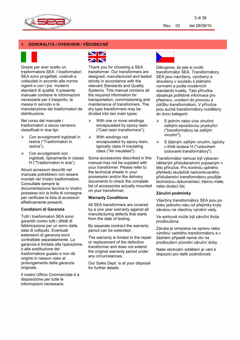
1. Indossare mezzi di protezione individuale: elmetti, guanti, scarpe antinfortunistiche, tuta da lavoro:
The operations of lifting, handling and transportation must be done by qualified staff, export on these kind of operations (slingers, crane operators, etc.), trained on the correct usage of slinging and handling methods and aware of the specific to which they are exposed and they can expose the other people. The staff must:
1. Wear individual means of protections: helmets, gloves, accident-prevention shoes, boiler suits:
Úkony zvedání, manipulace a přesun musí být prováděny pracovníky kvalifikovanými pro tuto činnost (vazači, jeřábníci atd.), vyškolenými pro správné používání lan a způsob přesunu a seznámenými s nebezpečím, kterému jsou oni sami vystaveni a kterému mohou vystavit jiné osoby. Pracovníci musí:
1. Použít osobní ochranné prostředky: ochrannou přilbu, rukavice, bezpečnostní pracovní obuv, pracovní oděv:
2. Far rispettare i segnali di divieto a terze persone ( è vietato il passaggio di personale sotto la zona di carico/movimentazione):
2. Command third people to respect prohibition notices (it is forbidden the transit of personnel under the loading/handling zone):
2. Nařídit třetím osobám, aby dodržovaly zákazy (nevstupovat pod zavěšené břemeno nebo do prostoru manipulace):

5 di 38
Rev. 03 del 28/09/10
ATTENZIONE!
Alla presenza di spigoli vivi (vedi disegno) e punte in prossimità della targa e sulla parte superiore del trasformatore; avvicinarsi con cautela utilizzare dispositivi di protezione quali guanti, scarpe anti-infortunistica e casco in tutte le fasi di movimentazione..
WARNING!
In case of sharp edges (see drawing) and points next to rating plate and on the upper part of the transformer; approach carefully and use means of protection as gloves, accident-prevention shoes and helmet during al the handling operations.
UPOZORNĚNÍ!
K ostrým hranám a rohům v blízkosti štítků a v horní části transformátoru (viz obrázek) přistupujte opatrně a během manipulace používejte ochranné prostředky - rukavice, pracovní obuv a ochrannou přilbu.
Mantenere sempre il trasformatore su un piano NON inclinato.
Always maintain the transformer in a NOT inclined plane.
Transformátor udržujte stále na NENAKLONĚNÉ rovině.
6 di 38
Rev. 03 del 28/09/10
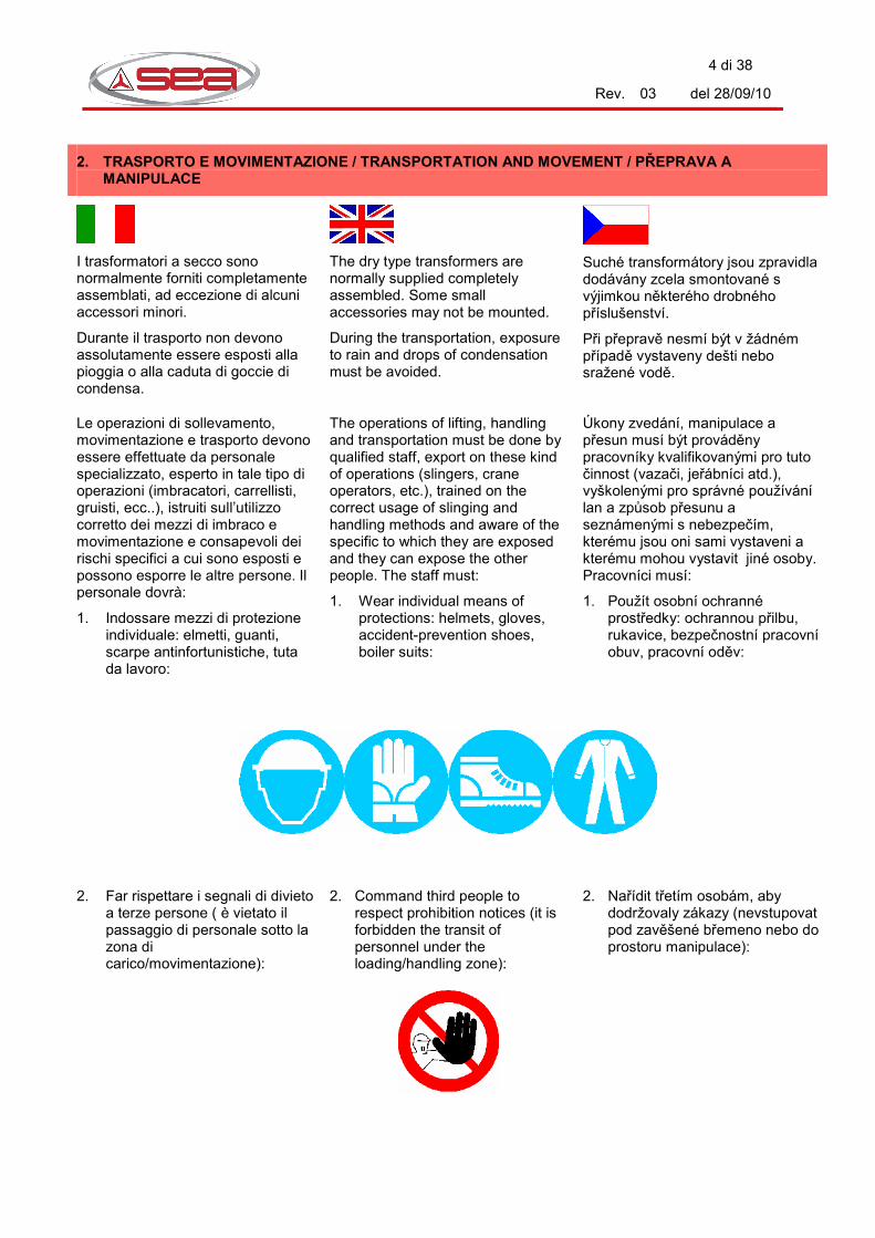
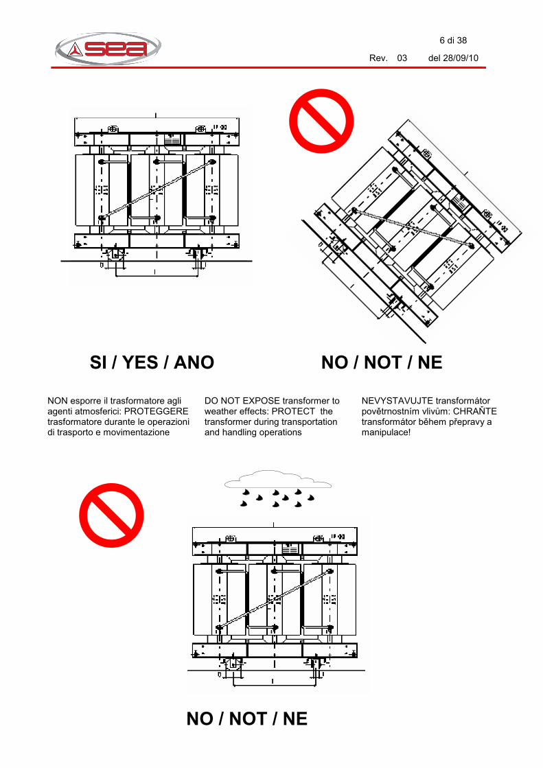
NON esporre il trasformatore agli agenti atmosferici: PROTEGGERE trasformatore durante le operazioni di trasporto e movimentazione
DO NOT EXPOSE transformer to weather effects: PROTECT the transformer during transportation and handling operations
NEVYSTAVUJTE transformátor povětrnostním vlivům: CHRAŇTE transformátor během přepravy a manipulace!
SI / YES / ANO
NO / NOT / NE
NO / NOT / NE

7 di 38
Rev. 03 del 28/09/10
2.1 Trasporto su camion
Il trasformatore è senza imballo, fissato solidamente al camion a mezzo di funi. Le ruote sono fissate al carrello in posizione di sicurezza.
2.2 Trasporto via nave o ferrovia
Normalmente in questi casi il trasformatore è fornito con imballo in legno, che può essere del tipo aperto o ermeticamente chiuso.
2.3 Movimentazione
Ogni trasformatore è dotato dei seguenti dispositivi:
1. 4 ruote o slitte per la traslazione;
2. Ganci per il traino;
3. 2 (o 4) golfari per il sollevamento.
2.1 Transportation by truck
The transformer is delivered without packaging, braced to the truck by ropes. The wheels are not mounted but are fixed in a safety position.
2.2 Transportation by sea or rail
Normally in these cases the transformer is properly packed in an open type or hermetic wooden case.
2.3 Movement
Each transformer is equipped with the following accessories:
1. 4 wheels or skids for translation;
2. Pulling eyes;
3. 2 (or 4) lifting lugs.
2.1 Přeprava na nákladním vozidle
Transformátor je dodáván nezabalený a je lany zajištěn na vozidle. Kolečka jsou upevněna v zabezpečené poloze.
2.2 Námořní přeprava nebo přeprava po železnici
V těchto případech je transformátor zabalen do otevřené nebo utěsněné dřevěné bedny.
2.3 Přesun na stanoviště
Každý transformátor je vybaven následujícím příslušenstvím:
1. 4 kolečka nebo lyžiny pro posun;
2. tažná oka;
3. 2 (příp. 4) závěsná oka
Durante le operazioni di movimentazione non transitare sotto e/o in prossimità del trasformatore; indossare sempre DPI (scarpe di sicurezza, casco, guanti) idonei:
During handling operations do not pass under and/or next to the transformer; always wear adequate DPI (shoes, helmet, gloves).
Během manipulace nevstupujte pod nebo do blízkosti transformátoru; používejte vždy osobní ochranné prostředky (rukavice, ochrannou přilbu, pracovní obuv).
NO / NOT / NE

8 di 38
Rev. 03 del 28/09/10
E’ possibile effettuare piccoli sollevamenti utilizzando idonei martinetti idraulici. I martinetti devono essere appoggiati alle traverse del carrello. E’ assolutamente vietato fare leva sul nucleo, sulle bobine e su tutti gli altri accessori del trasformatore.
Consultare la tabella 1 per scegliere in modo opportuno il diametro delle corde da utilizzare nel sollevamento, tenendo presente che devono essere sempre usate tante corde quante il numero di golfari e che l’angolo al vertice tra le corde non può mai essere superiore a 60°C.
1. Massa totale del trasformatore;
2. Carico di rottura della corda;
3. Diametro corda.
Suitable jacks can be used for minor lifting operations. Use the lower structural of the trolley as a jacking plate. It’s strictly forbidden to use the core, windings or other accessories as jacking plates.
Please refer to table 1 to choose the appropriate diameter of the ropes, taking into account that the number of ropes must be the same as the lifting lugs and the upper max. angle between ropes must be under 60°.
1. Total Weight;
2. Breaking load of each rope;
3. Rope diameter.
K mírnému nadzvednutí transformátoru může být použit hydraulický zvedák. Zvedák musí být nasazen k podvozku transformátoru. Je přísně zakázáno zvedat transformátor za jádro, vinutí nebo díly příslušenství.
Správný průměr lana pro zvedání se volí podle údajů v tabulce 1. Přitom je nutno dbát na to, že musí být použito tolik lan, kolik je závěsných ok, a že úhel ve vrcholu mezi lany nesmí být v žádném případě větší než 60°.
1. Celková hmotnost transformátoru;
2. Nosnost lana;
3. Průměr lana.
Tabella / Table / Tabulka 1
1 <1200 <1900 <2800 <3750 <5300 <6650 <8200 <11900 <16400 kg 2 4200 6600 9750 13100 18500 23150 28600 41400 57100 kg 3 8 10 12 14 16 18 20 24 28 mm
Per effettuare la traslazione con le ruote:
1. Montare le ruote nella direzione desiderata;
2. Spingere o tirare il trasformatore agendo direttamente sulle traverse del carrello. E’ possibile trainare il trasformatore anche agendo sugli appositi occhielli di traino sulle armature inferiori
3. Evitare nel modo più assoluto di spingere e/o tirare agendo sulle altre parti del trasformatore o sugli accessori.
To move the transformer on wheels:
1. Assemble the 4 supplied wheels in the right direction;
2. Push or pull applying force directly to the trolley structurals. It is also possible to pull it by means of the relevant pulling eyes, on lower core frames;
3. Avoid pushing and/or pulling on other parts of the transformer body and accessories.
Pro pohyb transformátoru na kolečkách postupujte následovně:
1. Na montujte kolečka pro požadovaný směr;
2. Transformátor tahejte nebo tlačte přímo za nosník podvozku. Transformátor může být také tažen za vlečná oka na spodním rámu;
3. V žádném případě netahejte nebo netlačte na ostatní díly transformátoru nebo příslušenství.

9 di 38
Rev. 03 del 28/09/10
3. RICEVIMENTO E IMMAGAZZINAGGIO / RECEPTION AND STORAGE / PŘEJÍMKA A SKLADOVÁNÍ
Al ricevimento del trasformatore si raccomanda di fare una verifica di quanto consegnato. La seguente lista di controllo potrà essere di aiuto per la verifica.
1. L’imballaggio è integro? 2. Ci sono segni di ruggine o
danni alla verniciatura? 3. I pressagioghi presentano
deformazioni o danneggiamenti?
4. Gli isolatori sono integri? 5. Gli accessori sono allegati o
montati sul trasformatore? 6. Il trasformatore presenta tracce
di pioggia o condensa? 7. La targa riporta esattamente le
caratteristiche del trasformatore ordinato?
Nel caso si riscontrasse qualche problema o mancanza, è necessario fare immediata riserva al trasportatore. Entro 3 giorni inviare un reclamo scritto, con documentazione fotografica a:
1. SEA S.p.A.; 2. Trasportatore; 3. Compagnia di Assicurazioni.
3.1 Regole generali per l’immagazzinaggio
I trasformatori in resina devono essere conservati in locale chiuso, pulito e ventilato, con temperature comprese tra –25 e + 40°C. Evitare nel modo più assoluto l’ immagazzinaggio in locali polverosi. Si raccomanda di proteggere il trasformatore e gli accessori da urti accidentali. Se il trasformatore è dotato di attacchi a spina, assicurarsi che gli attacchi restino protetti dalla apposita calotta per tutto il periodo di immagazzina-mento.
When the goods are received, we recommend you check them completely. The following check list may be used to help.
1. Is the packaging damaged? 2. Is the painting damaged? Is
there any rust? 3. Are the core clamping beams
misshapen or damaged? 4. Are the bushings in perfect
conditions? 5. Are all the accessories
mounted or enclosed with the transformer?
6. Do you see rain or moisture on transformers?
7. Does the rating plate show the transformer information as ordered?
In case of failure or damages, it is necessary to write a remark on the delivery note. Within 3 days a written complaint (including pictures) must be sent to:
1. SEA S.p.A.; 2. Your transportation company; 3. Your insurance company.
3.1 General rules for storage
The cast resin transformers must be stored indoors, in clean and ventilated rooms, with temperatures ranging from –25 to +40 °C. Dusty rooms must be avoided. Protect the transformer in order to avoid accidental crashes. In case of plug-in type connectors, be sure that the sockets are properly protected by their relevant cover for the entire storage period.
Při přejímce transformátoru doporučujeme zkontrolovat celý rozsah dodávky. Napomoct může následující seznam. 1. Je obal poškozen? 2. Je poškozen nátěr? Jsou vidět
někde stopy rzi? 3. Je zdeformován nebo
poškozen rám? 4. Jsou poškozeny průchodky
nebo připojovací praporce? 5. Je přiloženo příslušenství nebo
je namontováno na transformátor?
6. Jsou na transformátoru viditelné stopy deště nebo sražené vody?
7. Jsou uvedeny na výkonnostním štítku technické údaje, tak jak byl transformátor objednán?
V případě zjištění nedostatku nebo poškození je třeba napsat poznámku do dodacího listu. Do 3 dnů musí být písemná reklamace (včetně obrázků) zaslána na:
1. SEA S.p.A.; 2. Dopravce; 3. Pojišťovnu
3.1 Všeobecné předpisy pro skladování
Suché transformátory musí být skladovány ve vnitřních, čistých a dobře větraných prostorách při teplotách -25° až +40°. V žádném případě nesmí být skladovány v prašných prostorách. Transformátor a příslušenství musí být chráněny před mechanickým poškozením. V případě vybavení transformátoru svorkami pro konektorové připojení, musí být tyto po celou dobu skladování zakryty příslušnou krytkou.

10 di 38
Rev. 03 del 28/09/10
4. INSTALLAZIONE / INSTALLATION / INSTALACE
L’installazione del trasfomatore deve essere effettuata da personale competente, pratico di apparecchiature elettriche e di normativa sulla sicurezza.
Installation must be performed by skilled technicians, with experience in electrical appliances and safety rules.
Instalaci transformátoru musí provádět pracovníci s kvalifikací pro práci na elektrickém zařízení a se znalostí bezpečnostních předpisů.
ATTENZIONE!
Prima del posizionamento verificare l’eventuale presenza delle protezioni previste (armadi, pannelli, ripari ventilatori, etc..).
WARNING!
Before the positioning check if the protections (if any) are present (cable boxes, panels, fans protections, etc.).
UPOZORNĚNÍ!
Před ustavením na stanoviště zkontrolujte osazení ochran (jsou-li součástí dodávky) - kabelové skříně, panely, ochrany ventilátorů atd.
Per installare le ruote sollevare il trasformatore, posizionare sotto lo stesso dei supporti meccanici di resistenza adeguata (mantenendo comunque le funi in tensione), e avvitare le stesse, montandole nella direzione desiderata.
To install the wheels lift the transformer and put a mechanical support with adequate resistance under it (keep ropes stretched) and screw the wheels, mounting them in the desired direction.
Pro připevnění koleček nadzvedněte transformátor, podložte podvozek podložkou o dostatečné pevnosti (lana musí zůstat napnutá) a namontujte kolečka pro požadovaný směr.

11 di 38
Rev. 03 del 28/09/10
Per le operazioni di sollevamento e la scelta della fune idonea vedere apposite istruzioni nel presente Manuale d’uso e manutenzione.
For the lifting operations and the selection of the adequate rope please refer to the relevant instructions contained in Usage and Maintenance Manual.
Při zvedání a volbě odpovídajících lan se řiďte pokyny obsaženými v této příručce.
Mantenere sempre il trasformatore su un piano non inclinato.
Assicurarsi che le ruote siano correttamente bloccate.
Always maintain the transformer in a not inclined plane.
Be sure that the wheels have been correctly blocked.
Transformátor udržujte stále na nenakloněné rovině.
Přesvědčte se, zda jsou kolečka správně zablokována.

12 di 38
Rev. 03 del 28/09/10
Rimuovere eventuali imballi prima di mettere in servizio il trasformatore.
Remove packing (if any) before the start up of the transformer.
Odstraňte případné obaly před uvedením transformátoru do provozu.
In caso di stoccaggio provvisorio non sovrapporre più trasformatori o armadi.
In case of storage DO NOT lay one transformer or enclosure upon the other.
Při skladování nestavte transformátory nebo kryty na sebe!
SI / YES / ANO
NO / NOT / NE

13 di 38
Rev. 03 del 28/09/10
NON ESPORRE il trasformatore agli agenti atmosferici: PROTEGGERE il trasformatore durante le operazioni di trasporto e movimentazione.
DO NOT EXPOSE transformer to weather effects: PROTECT the transformer during transportation and handling operations.
NEVYSTAVUJTE transformátor povětrnostním vlivům: CHRAŇTE transformátor během přepravy a manipulace!
NO / NOT / NE
14 di 38
Rev. 03 del 28/09/10
4.1 Locale
Il locale deve consentire:
1. Rispetto delle distanze di sicurezza dalle parti in tensione (riferirsi alle normative vigenti). A tal fine si ricorda che la superficie esterna delle bobine in resina deve essere considerata parte in tensione. Il grado di protezione di un trasformatore in resina standard deve cioè essere considerato IP00;
2. Visibilità e accessibilità degli accessori;
3. Adeguata ventilazione: è richiesto un ricambio d’aria di circa 4,5 m3/minuto per ogni kW di perdite del trasformatore. Se la temperatura del locale è particolarmente alta (superiore a 40 °C) è necessario installare dei ventilatori estrattori. Consultare il nostro servizio commerciale in caso di dubbio;
4. Assenza di stillicidio e pericolo di inondazioni;
5. Salvo diversamente indicato nella specifica del Cliente, le condizioni di progetto in accordo a IEC 60076 sono:
� Temperatura massima 40°C;
� Temperatura minima –25°C;
� Altitudine ≤ 1000 m.
4.2 Fondazioni
Non ci sono particolari accorgimenti per le fondazioni. Il trasformatore può poggiare su rotaie o direttamente sul pavimento. Assicurarsi che siano idonei a sopportare il peso del trasformatore completo.
4.3 Antivibranti
In alcuni casi è richiesto che vengano attenuate quanto più possibile le vibrazioni che il trasformatore trasmette al pavimento. Possono a tal fine essere inseriti dei tamponi in gomma particolare tra la ruota ed il
4.1 Room
Main requirements for the room:
1. Suitable clearances from the walls to live parts (pls. Refer to your standards). Please note that the external surfaces of the cast resin coils must be considered as live parts, therefore the protection grade of a standard dry type transformer must be considered IP00;
2. Accessories and protecting devices must be easily readable and reachable;
3. Air flow, at least 4.5 m3/min per kW of total losses. In case of room temperatures greater than 40 °C, installation of an air extractor fan is recommended. Our Sales Dept. is at your disposal for further details;
4. No risk of water dropping and/or inundation;
5. Standard design values, according to IEC 60076 (if not otherwise indicated by the Customer):
� Max. room temperature 40°C;
� Min. room temperature –25°C;
� Altitude a.s.l. ≤ 1000 m.
4.2 Foundations
No particular requirements about foundations. Please be sure that floors or rails are able to withstand the total weight of the transformer.
4.3 Antivibration pads
Sometimes a particular dumping of vibrations trasmitted by the transformer to the floor is required. In this case 4 special rubber pads may be inserted between the wheels and floor. Please contact our Sales Dept. for further details.
4.4 HV connections
HV terminals may be located on the upper or lower part of each winding, but they are clearly marked by symbols 1U-1V-1W (or similar).
4.1 Stanoviště
Stanoviště musí splňovat:
1. Musí být dodrženy bezpečné vzdálenosti od živých částí (podle národních předpisů). Za živou část se považuje také vnější povrch zalitého vinutí. To znamená, že stupeň krytí standardního suchého transformátoru je IP00;
2. Příslušenství a ochranné přístroje musí být viditelné a přístupné;
3. Musí být zajištěno dostatečné větrání: je potřeba výměna vzduchu ca. 4,5 m3/min na kW celkových ztrát. Při vyšší teplotě na stanovišti (přes 40°C) musí být instalovány odtahové ventilátory. Pro podrobnosti kontaktujte obchodní oddělení.
4. Nesmí skapávat vodní kapky a nesmí být ohroženo zaplavením.
5. Pokud není v technické specifikaci uvedeno jinak, platí standardní hodnoty podle IEC 60076:
� Max. teplota vzduchu 40°C;
� Min. teplota vzduchu –25°C;
� Nadmořská výška ≤ 1.000 m.
4.2 Základy
Na základy nejsou kladeny zvláštní požadavky. Transformátor může být postaven na ocelové nosníky nebo přímo na podlahu. Musí být přitom zajištěno, že nosníky nebo podlaha unesou celkovou hmotnost transformátoru.
4.3 Ochrana proti chvění
V některých případech musí být tlumeno chvění přenášené z transformátoru na podlahu. K tomuto účelu mohou být vloženy tlumiče chvění mezi kolečko a podlahu. Pro podrobnosti kontaktujte obchodní oddělení.
4.4 Připojení vn
Svorky vn jsou umístěny na horní

15 di 38
Rev. 03 del 28/09/10
pavimento stesso. Consultare il nostro Ufficio Commerciale.
4.4 Collegamenti AT
I morsetti di MT possono essere realizzati nella parte superiore o inferiore delle bobine e sono sempre facilmente identificabili dalla marcatura 1U-1V-1W (o altre marcature equivalenti).
Regole generali:
1. Posizionare e fissare bene le connessioni in modo che il peso dei cavi o gli eventuali sforzi di cortocircuito non vadano a sollecitare i terminali presenti sulle bobine;
2. Studiare con attenzione il percorso dei cavi: deve essere assicurata una distanza di sicurezza, tra i cavi e la superficie delle bobine e/o i collegamenti del triangolo, ricavata dalle classi d’isolamento previste dalle norme. E’ possibile, adottare ad esempio, il percorso dei cavi con arrivo dall’alto (vedere le 3 foto successive).
General rules:
1. Be sure that connections are properly braced in order to avoid tensile strength on terminals due to the cable weights or dynamic forces arising between cables in case of short circuit;
2. To study with attention the distance of cables: emergency distance must be assured one, between cables and the surface of the coils and/or the connections of the triangle, obtained from the previewed classes of isolation from the norms. And' possible, to adopt as an example, the distance of cables with arrival from above (to see the 3 photos successive).
nebo dolní části každého vinutí a jsou označeny 1U-1V-1W (nebo podobně).
Všeobecné předpisy:
1. Přívodní kabely musí být upevněny tak, aby svorky nebyly namáhány hmotností kabelu nebo případným dynamickým namáháním při zkratu;
2. Pozorně zvažte trasu kabelů: musí být dodržena bezpečná vzdálenost od kabelu k povrchu vinutí a spojkám trojúhelníka v závislosti na izolační třídě podle norem. Jako příklad je možné vzít přívod kabelu shora (viz níže 3 fotky).
SI / YES / ANO SI / YES / ANO NO / NOT / NE
16 di 38
Rev. 03 del 28/09/10
Terminali standard
Il bloccaggio del capocorda avviene sul perno filettato del terminale, tra le due rondelle piane. La tabella 2 fornisce le coppie di serraggio ottimali.
1. Filettatura;
2. Coppia di serraggio.
Standard terminals
The connection of lugs must be executed on the threaded rod of each terminal, between the two plane washers. Refer to table 2 for suitable fixing torques.
1. Dimension of the rod;
2. Torque.
Standardní svorky
Kabelové oko se upevní na závitový svorník svorky mezi dvě ploché podložky. V tabulce 2 jsou uvedeny vhodné utahovací momenty.
1. Závit;
2. Utahovací moment.
Tabella / Table / Tabulka 2
1 M4 M5 M6 M8 M10 M12 M14 M16 M20
2 2 3 5 10 30 40 65 100 230 Nm
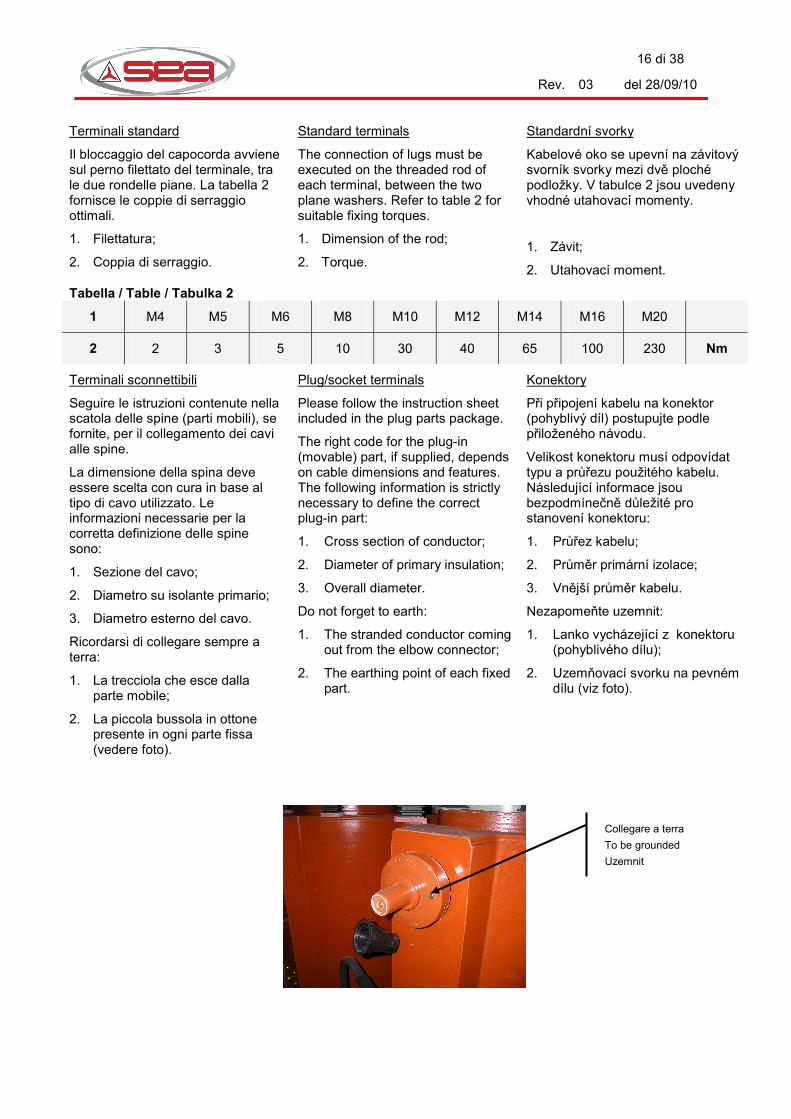
Terminali sconnettibili
Seguire le istruzioni contenute nella scatola delle spine (parti mobili), se fornite, per il collegamento dei cavi alle spine.
La dimensione della spina deve essere scelta con cura in base al tipo di cavo utilizzato. Le informazioni necessarie per la corretta definizione delle spine sono:
1. Sezione del cavo;
2. Diametro su isolante primario;
3. Diametro esterno del cavo.
Ricordarsi di collegare sempre a terra:
1. La trecciola che esce dalla parte mobile;
2. La piccola bussola in ottone presente in ogni parte fissa (vedere foto).
Plug/socket terminals
Please follow the instruction sheet included in the plug parts package.
The right code for the plug-in (movable) part, if supplied, depends on cable dimensions and features. The following information is strictly necessary to define the correct plug-in part:
1. Cross section of conductor;
2. Diameter of primary insulation;
3. Overall diameter.
Do not forget to earth:
1. The stranded conductor coming out from the elbow connector;
2. The earthing point of each fixed part.
Konektory
Při připojení kabelu na konektor (pohyblivý díl) postupujte podle přiloženého návodu.
Velikost konektoru musí odpovídat typu a průřezu použitého kabelu. Následující informace jsou bezpodmínečně důležité pro stanovení konektoru:
1. Průřez kabelu;
2. Průměr primární izolace;
3. Vnější průměr kabelu.
Nezapomeňte uzemnit:
1. Lanko vycházející z konektoru (pohyblivého dílu);
2. Uzemňovací svorku na pevném dílu (viz foto).
Collegare a terra
To be grounded
Uzemnit

17 di 38
Rev. 03 del 28/09/10
4.5 Collegamenti BT
Valgono anche in questo caso le regole generali indicate in 4.4
Prima di effettuare il collegamento ai cavi o alle sbarre, controllare (ed eventualmente rimuoverlo) che i terminali non presentino tracce di ossidazione. Seguire la tabella 2 per le coppie di serraggio.
4.5 LV connections
Even in this case please follow the main rule indicated in 4.4.
Before connections to cable or busbars, check the surface of the connecting flags on the transformer. In case of traces of oxidation, they must be removed. Follow table 2 for torque fixing.
4.5 Připojení nn
Také v tomto případě platí všeobecné předpisy v bodě 4.4.
Před připojením kabelů nebo sběrnic zkontrolujte povrch připojovacích praporců. Vykazují-li stopy oxidace, odstraňte je. Utahovací momenty jsou uvedeny v tabulce 2.
Controllare la distanza! Please check the distance!
Zkontrolujte vzdálenost!
18 di 38
Rev. 03 del 28/09/10
4.6 Collegamenti di terra
Ogni trasformatore è equipaggiato con 2 perni o piastrine di messa a terra, una sola delle quali completa di rosette e dado.
Una di queste deve essere collegata ad un efficiente impianto di terra con un conduttore di rame di sezione non inferiore a 16 mm2.
Seguire, in ogni caso, eventuali ulteriori prescrizioni vigenti nel vostro impianto o ditta.
4.7 Funzionamento in parallelo
Le regole che devono assolutamente essere rispettate per effettuare un parallelo sono:
1. I trasformatori devono avere lo stesso rapporto di trasformazione a vuoto;
2. I trasformatori devono avere lo stesso gruppo vettoriale.
Per effettuare un buon parallelo, è consigliabile rispettare anche le seguenti regole (in ordine di importanza):
1. I trasformatori devono avere la stessa tensione di cortocircuito;
2. I trasformatori devono avere all’ incirca la stessa potenza, ovvero differenza contenuta entro il 30%.
Prima di chiudere in modo definitivo il parallelo si consiglia di effettuare la seguente prova:
1. Collegare i due trasformatori lato MT e alimentarli;
2. Collegare insieme i neutri lato BT;
3. Misurare con un voltmetro la tensione tra le fasi corrispondenti lato BT: se è zero si può procedere con il parallelo.
La SEA S.p.A. non è in nessun caso responsabile per danni causati da un errato collegamento dei trasformatori.
4.8 Circuiti ausiliari
Collegare tutti i dispositivi presenti sul trasformatore al Vostro impianto,
4.6 Earthing
Each transformer is fitted with 2 earthing terminals or studs. Only one of them is equipped with the relevant washers and nut.
One of them must be connected to an efficient grounding plant by a copper conductor with a cross section of at least 16 sqm . Refer to the rules of your country and/or plant for further details.
4.7 Parallel connection
The following rules must be absolutely respected for parallel connections:
1. The transformers must have the same no load ratio;
2. The transformers must have the same vectorial group.
Moreover, to get the best performance from the two connected transformer, the following rules are recommended (in order of importance):
1. They must have the same impedance;
2. They must have a similar rating (allowable difference up to 30%).
Before proceeding with the final parallel connection, the follow-on check is strictly recommended:
1. Connect both transformers to the HV side in parallel and power them;
2. Connect the two neutral terminals together;
3. Measure the voltage between relevant LV terminals: if zero, you can proceed with the final parallel connection.
SEA is not responsible in any case for damages caused by wrong connection of transformers.
4.8 Auxiliary circuits
Connect all the signalling and protection devices to your plant, following the wiring diagram supplied with the transformer.
The cables for the connection
4.6 Uzemnění
Každý transformátor je vybaven 2 uzemňovacími svorkami, pouze jedna z nich je vybavena příslušnými podložkami a maticí.
Jedna ze svorek musí být spojena s účinným uzemněním měděným vodičem o průřezu alespoň 16 mm2.
V každém případě je nutné řídit se platnými předpisy v zemi instalace a vnitropodnikovými předpisy.
4.7 Paralelní chod
Při paralelním chodu musí být bezpodmínečně dodrženo:
1. Transformátory musí mít stejný převod;
2. Transformátory musí mít stejnou skupinu spojení.
Pro účinný paralelní chod by měla být dodržena následující pravidla (pořadí podle důležitosti):
1. Transformátory musí mít stejnou impedanci nakrátko;
2. Transformátory musí mít zhruba stejný výkon (přípustný rozdíl do 30%).
Před konečným připojením do paralelního chodu má být provedena následující kontrola:
1. Oba transformátory připojte paralelně pod napětí na straně VN;
2. Spojte nulové vodiče na straně NN;
3. Změřte napětí mezi odpovídajícími fázemi na straně NN: pokud je naměřená hodnota rovna nule, můžete dokončit připojení k paralelnímu chodu.
SEA S.p.A. v žádném případě neodpovídá za škody vzniklé chybným připojením transformátoru.
4.8 Pomocné obvody
Připojte všechny signalizační a ochranné přístroje k vašemu zařízení podle schémat dodaných s transformátorem.
Propojovací kabely mezi transformátorem a zařízením nejsou

19 di 38
Rev. 03 del 28/09/10
seguendo lo schema circuiti ausiliari sempre fornito con il trasformatore.
I cavi di collegamento tra il trasformatore e l’impianto non sono mai oggetto di fornitura standard.
Seguire le seguenti avvertenze:
1. Il collegamento tra le sonde (di tipo Pt100 o altro) poste sul trasformatore e il quadro va sempre effettuato mediante cavetto multipolare schermato;
2. Il collegamento a tutti i circuiti di segnalazione eventualmente posti sul trasformatore va effettuato con cavo di sezione minima 1,5 mm2
3. Il collegamento ai circuiti di potenza (ventilatori) e ai TA va effettuato con cavo di sezione minima 2,5 mm2;
4. Tenere separati quanto più possibile i percorsi dei cavi degli ausiliari dai cavi di potenza;
1. Non prelevare mai la tensione di alimentazione per centraline e altri dispositivi elettronici direttamente dalle sbarre BT del trasformatore. Se tale operazione deve per forza essere effettuata, consultare il nostro Servizio Tecnico.
between the transformer and plant are never supplied as standard.
Please follow the below instructions:
1. Connection between detectors (Pt100 or other) located on the transformer and control board must be made with a multicore screened cable
2. Connection to the signalling circuits on the transformer must be made with a cable with a cross section of at least 1.5 mm2
3. Connection to power circuits such as fans or CTs must be made with a cable with a cross section of at least 2.5 mm2
4. Please keep the track of the signal cables and the track of the power cables as far apart as possible
5. Do not feed electronic units and relays directly from the LV terminals of the transformer. If this operation cannot be avoided, please contact our Technical Service
standardně součástí dodávky.
Dbejte následujících pokynů:
1. Spojení čidel nacházejících se na transformátoru (Pt100 nebo jiné) a rozvaděčem proveďte mnohožilovým stíněným kabelem.
2. Propojení signalizačních obvodů proveďte kabelem o průřezu nejméně 1,5 mm2.
3. Připojení hlavních obvodů (ventilátorů) a přístrojových transformátorů proudu proveďte kabelem o průřezu nejméně 2,5 mm2.
4. Kabely pomocných obvodů veďte odděleně co možná nejdále od kabelů hlavních obvodů.
5. Elektronické jednotky a přístroje nenapájejte přímo ze svorek NN transformátoru. Pokud není jiná možnost, spojte se s naším technickým oddělením.

20 di 38
Rev. 03 del 28/09/10
5. MESSA IN SERVIZIO / START-UP / UVEDENÍ DO PROVOZU
Utilizzare la seguente lista di controllo prima della messa in servizio.
1. Controllare che le tensioni in targa siano quelle dell’impianto;
2. Controllare che i collegamenti sulla basetta cambio tensione siano in posizione corretta;
3. Controllare che tutte le basette cambio tensione siano collegate tutte per la stessa tensione;
4. Controllare che tutta la bulloneria delle connessioni sia serrata;
5. Controllare che tutti i cavi e/o le sbarre siano ammarrate;
6. Controllare che tutti gli accessori siano visibili e correttamente funzionanti;
7. Controllare il settaggio del termometro o della centralina elettronica (se previsti). Le temperature di allarme, sgancio e ventilazione (*) devono essere impostate in base alla sovra-temperatura prevista per il trasformatore (consultare la targa dati): Classe B (80 °C) Allarme: 125 °C Sgancio: 135 °C Ventilazione (*): 120-100 °C
Classe F (100 °C) Allarme: 145 °C Sgancio: 155 °C Ventilazione (*): 140-120 °C
Classe H (125 °C) Allarme: 170 °C Sgancio: 180 °C Ventilazione (*): 160-140 °C (*) La funzione “ventilazione” non è mai prevista nel termometro a quadrante. Per le centraline consultare gli schemi ed il manuale specifico dell’apparecchiatura in quanto
The following check list shall be used before start-up.
1. Compare the rated voltages of the plant to the rated voltage of transformer (indicated on rating plate);
2. Check the position of the tapping links;
3. Be sure that the position of the tapping links is the same on all windings;
4. Check the fixing torques of the connections;
5. Be sure that cables/busbars are correctly braced;
6. Check the auxiliaries are working correctly;
7. Set the contacts available on dial type thermometers or electronic monitoring units (if any). The setpoint temperatures must be set according to the estimated rise in transformer temperature (see rating plate): Class B (80 °C) Alarm: 125 °C Trip: 135 °C Fan (*): 120-100 °C
Class F (100 °C) Alarm: 145 °C Trip: 155 °C Fan (*): 140-120 °C
Class H (125 °C) Allarm: 170 °C Trip: 180 °C Fan (*): 160-140 °C (*) The “fan” function is not available with a dial type thermometer. To set the electronic monitoring device, please refer to its operating manual because the programming procedures and features may be different. Two setpoints are suggested
Seznam kontrol, které mají být provedeny před uvedením do provozu:
1. Ověřte, že hodnoty jmenovitých napětí na štítku transformátoru odpovídají připojeným zařízením.
2. Ověřte, že je nastavena správná odbočka.
3. Přesvědčte se, že je jsou odbočky nastaveny shodně na všech vinutích.
4. Ověřte dotažení šroubových spojů na svorkách.
5. Přesvědčte se, že všechny kabely a sběrnice jsou správně upevněny.
6. Ověřte funkčnost a viditelnost příslušenství.
7. Nastavte kontakty ručkového teploměru nebo elektronické vyhodnocovací jednotky (je-li k dispozici). Teploty pro výstrahu, vypnutí a nucené chlazení (*) musí být nastaveny podle dovoleného oteplení izolačního systému (viz štítek): Třída B (80°C) Výstraha: 125°C Vypnutí: 135°C Chlazení (*): 120-100°C Třída F (100°C) Výstraha: 145°C Vypnutí: 155°C Chlazení (*): 140-120°C Třída H (125°C) Výstraha: 170°C Vypnutí: 180°C Chlazení (*): 160-140°C
(*) U ručkového teploměru nelze nastavit funkci „nucené chlazení“. Elektronické vyhodnocovací jednotky se nastavují podle příslušné příručky, protože postupy mohou být různé.

21 di 38
Rev. 03 del 28/09/10
le possibilità e le modalità di settaggio variano da modello a modello. Il settaggio da noi suggerito prescrive due valori (ON-OFF) in modo da evitare dannosi cicli di accensione/spegnimento attorno al valore di settaggio. I circuiti di protezione che impiegano sonde tipo PTC e relè di temperatura non richiedono nessuna operazione di settaggio.
8. Verificare serraggio connessioni;
9. Verificare distanze di sicurezza;
10. Verificare collegamenti di terra;
11. Verificare isolamento BT;
12. Verificare funzionamento accessori.
(ON-OFF) for fan control to avoid dangerous On/Off cycling. The protecting circuits based on PTC detectors and temperature relays do not require any setting procedure.
8. Check connections tightening;
9. Check safety distances (cables, cable boxes, panels, etc.);
10. Check earthing connections;
11. Check LV insulation;
12. Check accessories functioning.
Jsou dvě doporučené teploty pro nastavení nuceného chlazení (ZAP-VYP), aby se zabránilo nebezpečným cyklům zapínání a vypínání.
Ochranné obvody a vyhodnocovací jednotky pro termistory PTC nevyžadují žádné nastavení.
8. Ověřte dotažení spojů;
9. Ověřte bezpečné vzdálenosti;
10. Ověřte připojení uzemnění;
11. Ověřte izolaci nn;
12. Ověřte funkčnost příslušenství.
Solo per i trasformatori in aria
13. Eliminare eventuali tracce di polvere depositata sul trasformatore, ponendo particolare attenzione ai blocchetti di estremità e ai separatori interni nell’avvolgimento MT. Per effettuare tale operazione servirsi di un getto di aria secca, possibilmente calda.
14. Se il trasformatore è stato immagazzinato per lungo tempo in un ambiente molto umido, senza adeguata protezione, essiccare gli avolgimenti nel seguente modo:
Cortocircuitare avvolgimento di BT con una sbarra o treccia di sezione pari o simile a quella delle sbarre del trasformatore; Collegare avvolgimento di MT per la tensione massima;
For air type transformers only
13. Remove any dust deposits from the transformer, paying particular attention to the axial insulating supports and insulating spacers inside the HV windings. To remove dust use dry, hot jet of air.
14. In case of long storage periods in a very humid room, without suitable protection, proceed to dry the transformer windings following the instructions below indicated:
Short circuit the LV windings, by means of a copper bar or stranded conductor. The cross section must be equal or similar to the cross section of the transformer LV terminals;
Connect the HV tapping links for the highest voltage; To feed side MT with one such
Pouze pro transformátory s nezalitým vinutím
13. Odstraňte případnou vrstvu prachu z transformátoru. Zvláštní pozornost je nutno věnovat podpěrám a vnitřním rozpěrkám vinutí VN. K odstranění prachu použijte suchý, nejlépe horký vzduch.
14. Pokud byl transformátor delší dobu skladován bez přiměřené ochrany ve velmi vlhkém prostředí, musí být vinutí vysušena podle níže uvedených pokynů: Spojte vinutí NN nakrátko sběrnicí nebo slaněným vodičem o stejném nebo podobném průřezu, jako jsou připojovací praporce nn; Na vinutí VN nastavte odbočku pro nejvyšší napětí; Stranu VN napájejte takovým

22 di 38
Rev. 03 del 28/09/10
Alimentare il lato MT con una tensione tale da far circolare una corrente non superiore alla nominale indicata sulla targa e lasciare il trasformatore in questa condizione per circa 24 ore; Ricordarsi di togliere il cortocircuito lato BT alla fine del trattamento.
In caso di dubbi consultare sempre il nostro servizio tecnico o commerciale.
tension to make circular one not advanced current to the noun indicated on the plate and to leave the transformer in this condition for approximately 24 hours; Do not forget to remove the short circuit at the LV side after treatment.
In case of doubt, please refer to our technical or sales service.
napětím, které vytvoří takový proud, který není vyšší jak jmenovitý proud podle štítku ponechte transformátor v tomto provozu přibližně 24 hodin; Po skončení vysoušení nezapomeňte odstranit zkratovací propoje! Při pochybnostech se obraťte na naše technické oddělení.

23 di 38
Rev. 03 del 28/09/10
5.1 Basetta commutazione
Il trasformatore è normalmente dotato di una basetta di commutazione a 3 o a 5 gradini (vedere targa dati fissata sul trasformatore), ricavata direttamente sulla resina della bobina di MT.
Su tale basetta sono riportati 4 (o 6) terminali, marcati con numeri da 3 a 6 (8). Due di questi terminali, uno con numero dispari ed uno con numero pari sono collegati tra di loro da una barretta. Consultare la targa commutazione fissata al trasformatore per avere una corrispondenza tra i vari collegamenti e le tensioni disponibili.
Scollegare il trasformatore dalla rete e metterlo a terra prima di operare sulla basetta.
Per cambiare la posizione della basetta, operare come segue:
1. svitare le viti che fissano la barretta “A”.
2. riposizionare la barretta “A” come desiderato (consultare la targa commutazione, normalmente fissata all’armatura superiore).
3. Fissare nuovamente le viti, rispettando la sequenza di montaggio originale (morsetto / rondella ottone / barretta / rondella acciaio / rondella elastica / vite).
4. Controllare che su ogni basetta siano collegati solo due morsetti tramite una sbarretta, solo uno pari con solo uno dispari.
5. Controllare che tutte le bobine siano collegate sulla stessa posizione.
5.1 Tapping board
Each transformer is normally fitted with a 3 or 5 position tap changer (see the rating plate on the transformer body for further details). The board is embedded directly in the winding casting resin.
On the tapping board there are 4 (or 6) terminals, marked by numbers from 3 to 6 (8). A couple of these terminals, one even and one odd, are connected together by a conducting link.
Please refer to the tapping plate so that the available connections and relevant rated voltages correspond.
De-energize and earth the transformer before operations.
In order to change the selected tap, operate as follows:
1. Remove the fixing bolts of the tapping link “A”.
2. Choose a different position for the link (refer to the rating plate, normally fixed to the upper core clamp).
3. Re-fix the tapping link, taking care that the assembling sequence is the same as the original one (tapping terminal / brass washer / link / steel washer / elastic washer / bolt).
4. Be sure in each winding that only 2 tapping terminals are connected together by means of one link, only one even to only one odd.
5. Be sure that all windings are connected for the same voltage.
5.1 Přepojovaní odboček
Transformátor je běžně vybaven svorkovnicí odboček a spojkou pro 3 nebo 5 poloh (viz výkonnostní štítek transformátoru). Svorkovnice je přímo na zalitém vinutí.
Na svorkovnici odboček jsou 4 (příp. 6) svorek, které jsou označeny čísly od 3 do 6 (8). Dvě tyto svorky – jedna s lichým a jedna se sudým číslem – se propojí spojkou. Možná spojení a tomu odpovídající napětí jsou uvedeny na štítku spojení.
Před provedením nastavení musí být transformátor odpojen od sítě a uzemněn.
Změna nastavení odbočky se provede následovně:
1. Povolte šrouby spojky "A";
2. Spojku "A" nastavte do požadované polohy (podle štítku spojení umístěného obvykle na horní stahovací konstrukci).
3. Dotáhněte opět šrouby. Při montáži dodržte původní pořadí (svorka odbočky / mosazná podložka / spojka / ocelová podložka / pružná podložka / šroub).
4. Ujistěte se, že na každé svorkovnici odboček jsou pouze dvě svorky propojené spojkou, a to jedna svorka se sudým a jedna s lichým číslem.
5. Ujistěte se, že vinutí všech fází je připojeno na stejné napětí.

24 di 38
Rev. 03 del 28/09/10
Basetta commutazione ± 2x2,5 % Tapping board ± 2x2.5 % Svorkovnice odboček ± 2x2,5%
La posizione va scelta in modo da adattare quanto più possibile la tensione primaria del trasformatore a quella disponibile nell’impianto. Con la stessa tensione di rete si può agire sul commutatore per regolare la tensione lato BT nel seguente modo:
� Collegamento verso le tensioni più alte della nominale: si ottiene un abbassamento della tensione BT;
� Collegamento verso le tensioni più basse della nominale: si ottiene un innalzamento della tensione BT.
Nota: Non collegare la basetta sulla posizione della tensione inferiore al nominale se la rete fornisce una tensione superiore al nominale.
5.2 Cambio tensione primaria
Il trasformatore può essere previsto per funzionare a due o più tensioni primarie. In tutti questi casi è sempre fornita una targa che riassume completamente tutte le modalità di funzionamento con i relativi collegamenti.
Le principali possibilità di cambio tensione primaria sono le seguenti:
Serie/Parallelo
due tensioni sono una il doppio dell’altra, ad esempio 10 – 20 kV.
L’avvolgimento è diviso in due sezioni perfettamente identiche che possono essere collegate in serie o in parallelo. Ogni sezione è dotata di una propria basetta commutazione (cfr. 5.1)
I collegamenti serie/parallelo sono realizzati esternamente alle bobine, quindi con il trasformatore sono
Connection of the tapping board must be chosen as close as possible to the mains level.
Supposing a constant rated voltage level on the network, the tapping board can be used to regulate the low voltage side, as follows:
� Connection to voltages higher than the rated one: the LV decreases;
� Connection to voltages lower than rated one: the LV increases.
Note: Do not connect the tapping board for the lowest voltages when the supply voltage is higher than the rated one.
5.2 Change of voltage level
The transformer may be equipped with an HV winding designed to be reconnected at different primary voltages. In these cases a suitable plate summarizing all the working conditions and relevant connection diagrams is always supplied.
The main connection diagrams are the following:
Series Parallel
One voltage level is twice the other, example 10-20 kV.
The HV winding is divided into two parts, perfectly equal. They can be connected in series or in parallel. Each section is fitted with its own tapping board (cfr. 5.1).
The connections are made externally, i.e. some additional connecting bars/tubes are supplied loose.
Do not forget to remove the connecting bars for the “series”
Nastavení odboček se volí tak, aby nastavená hodnota napětí byla co možná nejblíže skutečnému napětí sítě. Přepojením odboček lze řídit napětí na straně NN následovně:
� Nastavení odbočky na vyšší napětí: napětí NN se sníží;
� Nastavení odbočky na nižší napětí: napětí NN se zvýší
Upozornění: Pokud je napětí sítě vyšší než jmenovité napětí, nesmí být nastavena odbočka na nižší napětí.
5.2 Změna primárního napětí
Transformátor může být konstruován pro provoz se dvěma nebo více různými primárními napětími. V těchto případech je dodáván štítek spojení zahrnující všechny druhy provozu a odpovídající propojení svorek.
Nejdůležitější schémata spojení jsou:
Sériové a paralelní spojení
Jedno napětí je dvojnásobkem druhého, například 10 - 20 kV. Vinutí je rozděleno na dvě zcela stejné části, které mohou být spojeny buď do série nebo paralelně. Každý díl vinutí má vlastní svorky pro přepojení odboček (viz 5.1).
Sériové a paralelní spojení se provádí vně vinutí spojkami, které jsou přibaleny k transformátoru. Uschovejte je pro budoucí změnu napětí.
Nezapomeňte odstranit spojky pro sériové spojení při změně na paralelní a naopak.

25 di 38
Rev. 03 del 28/09/10
sempre forniti i materiali per effettuarli entrambi. Conservare tali materiali per i futuri cambi tensione.
Ricordarsi sempre di rimuovere la sbarra di collegamento “serie” quando si effettua il collegamento “parallelo” e viceversa.
Esclusione
Le due tensioni differiscono poco l’una dall’altra, ad esempio 15 – 20 kV
Alcune parti interne dell’avvolgimento di MT vengono escluse o collegate in serie/parallelo.
In questi casi sulla resina vengono ricavate altre basette, molto simili alla basetta commutazione, ma i morsetti sono marcati con lettere anziché con numeri.
Stella/Triangolo
Le due tensioni stanno tra loro nel rapporto 1,732, ad esempio 6,35-11 kV.
In questi casi il collegamento è esterno alle bobine (cfr. 5.2.1), quindi sono forniti tutti i materiali per effettuare i collegamenti possibili.
Ricordarsi sempre di rimuovere la sbarra di collegamento “stella” quando si effettua il collegamento “triangolo” e viceversa.
Soluzioni miste
Componendo in varia maniera le 3 soluzioni sopra descritte possono essere realizzati molti altri collegamenti, ad esempio 8,4 – 20 kV
connection when the “parallel” connection is executed (or viceversa).
Exclusion
The difference between the voltages is quite small, for example 15-20 kV.
An internal portion of the HV winding is excluded or series/parallel connected. With this technical solution, a relevant connecting board, strictly similar to the tapping board, is made. The terminals are marked by letters instead numbers.
Star/Delta
The ratio between the two voltages is 1.732, for example 6.35-11 kV.
The star/delta connection is performed by external plates/bars, some of them are supplied loose.
Do not forget to remove the connecting bars for the “star” connection when the “delta” connection is executed (or viceversa).
Other connections
Combining the three a.m. solutions in different ways, a lot of other possibilities are allowable, for example 8.4 – 20 kV.
Exkluze
Rozdíl mezi dvěma napětími je malý, například 15 - 20 kV.
Vnitřní části vinutí VN jsou odpojeny nebo připojeny sériově/paralelně. V tomto případě jsou na vinutí další svorky se spojkami podobné svorkám pro přepojování odboček. Svorky jsou značeny písmeny místo čísel.
Hvězda / trojúhelník
Dvě napětí jsou v poměru 1,732, například 6,35-11 kV.
V těchto případech je provedeno spojení vnějšími spojkami, které jsou přibaleny k transformátoru.
Nezapomeňte odstranit spojky pro spojení do hvězdy při změně na spojení do trojúhelníka a naopak.
Jiná spojení
Různými kombinacemi tří výše uvedených provedení může být provedeno mnoho jiných spojení, například 8,4 - 20 kV.
La resina è da considerarsi parte in tensione: non appoggiarsi –Non toccare il trasformatore fino a che questo è in tensione.
Resin has to be considered as energized: Do not lean against – Do not touch the transformer while it is energized.
Izolační pryskyřice musí být považována za živou část: Nedotýkejte se transformátoru pod napětím.
26 di 38
Rev. 03 del 28/09/10
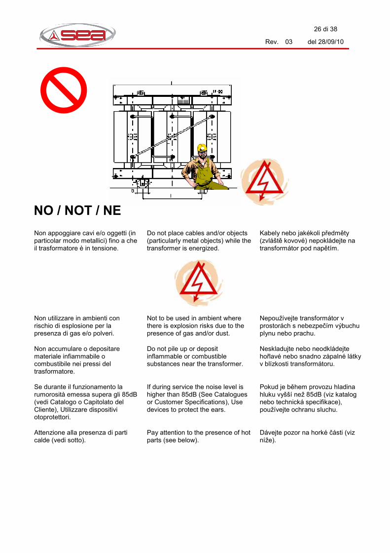
Non appoggiare cavi e/o oggetti (in particolar modo metallici) fino a che il trasformatore è in tensione.
Do not place cables and/or objects (particularly metal objects) while the transformer is energized.
Kabely nebo jakékoli předměty (zvláště kovové) nepokládejte na transformátor pod napětím.
Non utilizzare in ambienti con rischio di esplosione per la presenza di gas e/o polveri.
Not to be used in ambient where there is explosion risks due to the presence of gas and/or dust.
Nepoužívejte transformátor v prostorách s nebezpečím výbuchu plynu nebo prachu.
Non accumulare o depositare materiale infiammabile o combustibile nei pressi del trasformatore.
Do not pile up or deposit inflammable or combustible substances near the transformer.
Neskladujte nebo neodkládejte hořlavé nebo snadno zápalné látky v blízkosti transformátoru.
Se durante il funzionamento la rumorosità emessa supera gli 85dB (vedi Catalogo o Capitolato del Cliente), Utilizzare dispositivi otoprotettori.
If during service the noise level is higher than 85dB (See Catalogues or Customer Specifications), Use devices to protect the ears.
Pokud je během provozu hladina hluku vyšší než 85dB (viz katalog nebo technická specifikace), používejte ochranu sluchu.
Attenzione alla presenza di parti calde (vedi sotto).
Pay attention to the presence of hot parts (see below).
Dávejte pozor na horké části (viz níže).
NO / NOT / NE

27 di 38
Rev. 03 del 28/09/10
Il trasformatore deve essere messo in servizio alle condizioni ambientali (temperature massime e minime, umidità, polvere conduttrice, atmosfera aggressiva, altitudine, influenze esterne, vibrazioni) definite dalle norme IEC in vigore e in sede di Conferma d’Ordine di vendita, se più restrittive. S.E.A. S.p.A. non si assume responsabilità alcuna per fonti di pericolo provocate da installazione in condizioni ambientali differenti rispetto a quanto riportato in sede di Conferma d’Ordine di Vendita.
The transformer must be energized with the environmental conditions (max and min temperature, humidity, conductor powder, aggressive atmosphere, height, external influence, vibrations) defined by current IEC norms and in the Order Confirmation, if more restrictive. S.E.A. S.p.A. does not assume any responsibility for danger sources caused by installation in environmental conditions different from what described in Order Confirmation.
Transformátor musí být uveden do provozu za klimatických podmínek podle platných norem IEC nebo podle potvrzení objednávky stanovující případně přísnější podmínky (maximální a minimální teplota, vlhkost vzduchu, prašnost, agresivní prostředí, výška, vnější vlivy). S.E.A. S.p.A. nepřebírá zodpovědnost za nebezpečí způsobená instalací v klimatických podmínkách, které jsou odlišné od potvrzení objednávky.

28 di 38
Rev. 03 del 28/09/10
6. MANUTENZIONE / MAINTENANCE / ÚDRŽBA
Tutta la manutenzione deve eseguita con trasformatore scollegato dalle linee MT / BT e collegato a terra in modo ben visibile.
Tutta la manutenzione deve essere fatta da personale esperto.
Maintenance must be performed with de-energized transformers, solidly connected to the earth plant.
Maintenance must be performed by skilled technicians.
Údržba smí být prováděna na odpojeném a viditelně uzemněném transformátoru.
Údržba musí být prováděna kvalifikovanými pracovníky.
Attenzione alla temperatura del trasformatore prima di effettuare qualsiasi operazione di pulizia, manutenzione e cablaggio
Pay attention to the temperature of transformer before starting each operation of cleaning, maintenance and wiring.
Věnujte pozornost teplotě transformátoru před každým čistěním, údržbou a připojováním.
In caso di necessità di sostituzione di componenti per danneggiamento o altro, utilizzare componenti con le stesse caratteristiche di affidabilità e sicurezza di quelli forniti da S.E.A. S.p.A.. In caso di dubbio contattare il nostro Servizio Commerciale o Servizio Tecnico.
In case there is the need to substitute components for damages or other reasons, use components with the same characteristics of fiability and safety of the ones supplied by S.E.A. S.p.A.. In case of doubt please get in contact with our Commercial Service or Technical Service.
V případě potřeby náhrady dílů z důvodu poškození nebo z jiných důvodů použijte díly se stejnými vlastnostmi, spolehlivostí a bezpečností, jako jsou dodávané S.E.A. S.p.A. V případě nejasností se spojte s naším obchodním nebo technickým oddělením.
Per accedere alle parti superiori del trasformatore:
1. Non arrampicarsi sul trasformatore;
2. Utilizzare piattaforme di sollevamento o scale di accesso idonee;
3. Assicurarsi che il trasformatore abbia raggiunto una temperatura non pericolosa.
To reach the upper parts of the transformer:
1. Do not climb up the transformer;
2. Use lifting platforms or adequate ladders;
3. Be sure that the transformer has reached a not dangerous temperature.
K dosažení dílů v horní části transformátoru:
1. Nelezte na transformátor;
2. Použijte zvedací plošinu nebo přiměřený žebřík;
3. Ujistěte se, že transformátor nedosáhl nebezpečné teploty.

29 di 38
Rev. 03 del 28/09/10
ATTENZIONE!
Alla presenza di spigoli vivi (vedi disegno) e punte in prossimità della targa e sulla parte superiore del trasformatore; avvicinarsi con cautela utilizzare dispositivi di protezione quali guanti, scarpe anti-infortunistica e casco in tutte le fasi di movimentazione.
WARNING!
In case of sharp edges (see drawing) and points next to rating plate and on the upper part of the transformer; approach carefully and use means of protection as gloves, accident-prevention shoes and helmet during al the handling operations.
UPOZORNĚNÍ!
K ostrým hranám a rohům v blízkosti štítků a v horní části transformátoru (viz obrázek) přistupujte opatrně a během manipulace používejte ochranné prostředky – rukavice, pracovní obuv a ochrannou přilbu.

30 di 38
Rev. 03 del 28/09/10
Attenzione a non abbandonare bulloni, attrezzi o oggetti metallici sul trasformatore.
Pay attention not to abandon nuts, tools or metallic objects on the transformer.
Ujistěte se, že jste na transformátoru nenechali šrouby, nářadí nebo kovové předměty
ATTENZIONE!
Per le operazioni di pulizia non utilizzare abrasivi, solventi o sostanze che possano danneggiare o compromettere le funzionalità del trasformatore o delle apparecchiature.
WARNING!
For the general cleaning operations do not use abrasive, solvent or substances that could damage or prejudice the functionality of the transformer or of the fittings.
UPOZORNĚNÍ!
K čištění nepoužívejte brusné prostředky, rozpouštědla nebo látky, které poškodit nebo ovlivnit činnost transformátoru nebo příslušenství.
31 di 38
Rev. 03 del 28/09/10
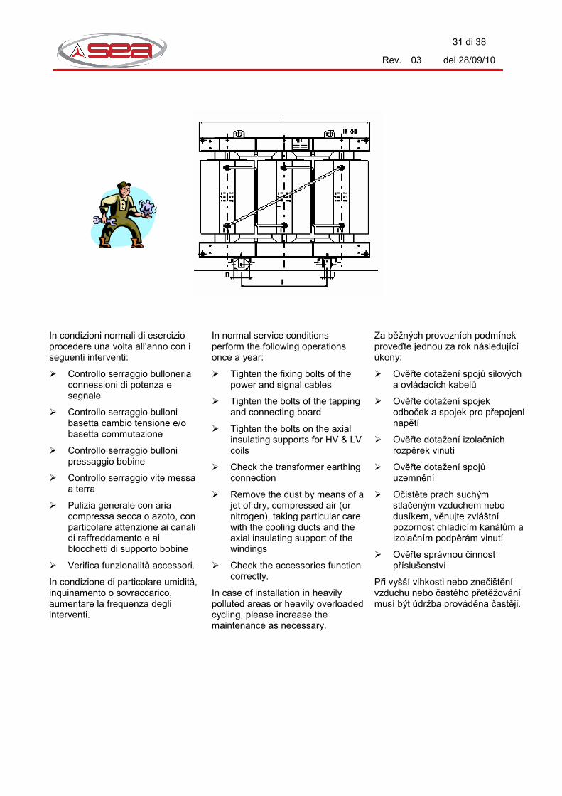
In condizioni normali di esercizio procedere una volta all’anno con i seguenti interventi:
� Controllo serraggio bulloneria connessioni di potenza e segnale
� Controllo serraggio bulloni basetta cambio tensione e/o basetta commutazione
� Controllo serraggio bulloni pressaggio bobine
� Controllo serraggio vite messa a terra
� Pulizia generale con aria compressa secca o azoto, con particolare attenzione ai canali di raffreddamento e ai blocchetti di supporto bobine
� Verifica funzionalità accessori.
In condizione di particolare umidità, inquinamento o sovraccarico, aumentare la frequenza degli interventi.
In normal service conditions perform the following operations once a year:
� Tighten the fixing bolts of the power and signal cables
� Tighten the bolts of the tapping and connecting board
� Tighten the bolts on the axial insulating supports for HV & LV coils
� Check the transformer earthing connection
� Remove the dust by means of a jet of dry, compressed air (or nitrogen), taking particular care with the cooling ducts and the axial insulating support of the windings
� Check the accessories function correctly.
In case of installation in heavily polluted areas or heavily overloaded cycling, please increase the maintenance as necessary.
Za běžných provozních podmínek proveďte jednou za rok následující úkony:
� Ověřte dotažení spojů silových a ovládacích kabelů
� Ověřte dotažení spojek odboček a spojek pro přepojení napětí
� Ověřte dotažení izolačních rozpěrek vinutí
� Ověřte dotažení spojů uzemnění
� Očistěte prach suchým stlačeným vzduchem nebo dusíkem, věnujte zvláštní pozornost chladicím kanálům a izolačním podpěrám vinutí
� Ověřte správnou činnost příslušenství
Při vyšší vlhkosti nebo znečištění vzduchu nebo častého přetěžování musí být údržba prováděna častěji.

32 di 38
Rev. 03 del 28/09/10
6.1 Interventi straordinari
Si descrivono a seguito alcuni interventi di manutenzione straordinaria che potrebbero rendersi necessari durante la vita del trasformatore.
Per ulteriori informazioni e/o operazioni non descritte a seguito, potete contattare il nostro Servizio Commerciale.
Sostituzione termometro:
Sfilare il bulbo dalla sua posizione originale facendo attenzione a non danneggiare il capillare. Scollegare i contatti e togliere le viti di fissaggio alla staffa.
Rimontare il nuovo termometro. Ricordarsi di effettuare il settaggio dei contatti (vedere capitolo 5.)
Sostituzione termosonda:
Sfilare la termosonda tirando delicatamente il cavetto di collegamento. Rimontare la nuova termosonda ed il relativo cavetto nella posizione originale. Il cavetto ha normalmente una lunghezza molto più lunga del necessario. L’eccedenza deve essere arrotolata e tenuta bloccata in posizione distante da connessioni e avvolgimenti.
6.1 Non routine maintenance
You will find, indicated below, some non-routine maintenance operations that may be necessary during the life of the transformer.
Our Sales Dept. is at your disposal for further details or other operations not described below.
Replacing the thermometer:
Disconnect the thermometer and remove it from the bracket being careful not to damage the capillary.
Remount the new thermometer.
Do not forget to re-set the contacts (see chap. 5)
Replacing the temperature detector:
Remove the temperature detector carefully pulling the connecting cable. Remount the new detector and relevant cable in the original position. The connecting cable is normally longer than necessary. Do not cut the cable but leave it wound and braced to the core clamp in order to avoid contact with the windings and/or terminals.
6.1 Mimořádná údržba
V následujícím je popsána mimořádná údržba, která může být nutná během životnosti transformátoru.
Pro další informace nebo úkony, které zde nejsou uvedeny, se spojte s naším obchodním oddělením.
Výměna teploměru:
Odmontujte hlavici teploměru opatrně, abyste nepoškodili kapiláru. Odpojte kontakty a povolte upevňovací šrouby na objímce. Namontujte nový teploměr. Nezapomeňte nastavit kontakty (viz kapitola 5).
Výměna teplotního čidla:
Vytáhněte teplotní čidlo opatrně za kabel. Nasaďte opatrně teplotní čidlo s příslušným kabelem do původní polohy. Kabel je v běžně mnohem delší než je nutné. Přesahující délka musí být stočena a zajištěna v bezpečné vzdálenosti od připojovacích svorek a vinutí.

33 di 38
Rev. 03 del 28/09/10
7. MESSA FUORI SERVIZIO / SHUT-OFF / UVEDENÍ MIMO PROVOZ
Qualora fosse necessario mettere fuori servizio il trasformatore a causa di un guasto o una sostituzione, procedere come segue:
1. Assicurarsi che l’impianto sia fuori tensione e collegato a terra;
2. Scollegare i morsetti MT e BT;
3. Montare i coperchietti protettivi degli isolatori a spina (se previsti);
4. Togliere i collegamenti ausiliari;
5. Togliere il collegamento di terra;
6. Togliere le ruote e fissarle in posizione di sicurezza.
Se necessario, avvisare il nostro Servizio Commerciale.
Should it be necessary to put the transformer out of service due to damage or replacement with a new unit, please proceed as follows:
1. Be sure that the plant is de-energized and earthed;
2. Disconnect HV and LV terminals;
3. Fit the protecting covers of the plug-in terminals (if provided);
4. Remove the connection to the auxiliary circuits;
5. Disconnect the earthing conductor;
6. Remove the wheels and fix them in their safety position.
If necessary, inform our Sales Dept.
Pokud má být transformátor uveden mimo provoz kvůli poruše nebo výměně dílu, postupujte následovně:
1. Ujistěte se, že transformátor není pod napětím a je řádně uzemněn;
2. Odpojte svorky VN a NN;
3. Namontuje krytky na konektory (jsou-li použity);
4. Odpojte kontakty pomocných obvodů;
5. Odpojte uzemnění;
6. Sundejte kolečka a upevněte je v bezpečné poloze.
Pokud je to nutné, informujte naše obchodní oddělení.
34 di 38
Rev. 03 del 28/09/10
8. I PROBLEMI PIU’ COMUNI / TROUBLE SHOOTING / NEJČASTĚJŠÍ PROBLÉMY
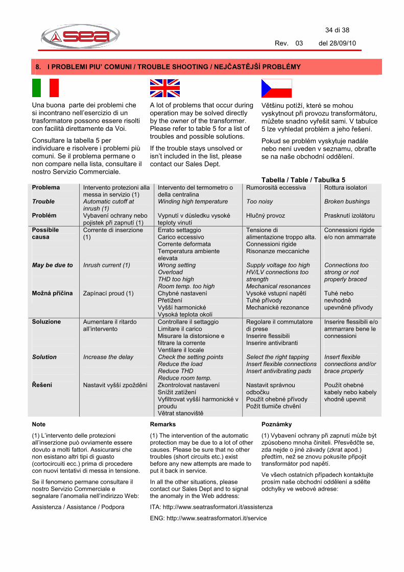
Una buona parte dei problemi che si incontrano nell’esercizio di un trasformatore possono essere risolti con facilità direttamente da Voi.
Consultare la tabella 5 per individuare e risolvere i problemi più comuni. Se il problema permane o non compare nella lista, consultare il nostro Servizio Commerciale.
A lot of problems that occur during operation may be solved directly by the owner of the transformer. Please refer to table 5 for a list of troubles and possible solutions.
If the trouble stays unsolved or isn’t included in the list, please contact our Sales Dept.
Většinu potíží, které se mohou vyskytnout při provozu transformátoru, můžete snadno vyřešit sami. V tabulce 5 lze vyhledat problém a jeho řešení.
Pokud se problém vyskytuje nadále nebo není uveden v seznamu, obraťte se na naše obchodní oddělení. Tabella / Table / Tabulka 5
Problema Trouble Problém
Intervento protezioni alla messa in servizio (1) Automatic cutoff at inrush (1) Vybavení ochrany nebo pojistek při zapnutí (1)
Intervento del termometro o della centralina Winding high temperature Vypnutí v důsledku vysoké teploty vinutí
Rumorosità eccessiva Too noisy Hlučný provoz
Rottura isolatori Broken bushings Prasknutí izolátoru
Possibile causa May be due to Možná příčina
Corrente di inserzione (1) Inrush current (1) Zapínací proud (1)
Errato settaggio Carico eccessivo Corrente deformata Temperatura ambiente elevata Wrong setting Overload THD too high Room temp. too high Chybné nastavení Přetížení Vyšší harmonické Vysoká teplota okolí
Tensione di alimentazione troppo alta. Connessioni rigide Risonanze meccaniche Supply voltage too high HV/LV connections too strength Mechanical resonances Vysoké vstupní napětí Tuhé přívody Mechanické rezonance
Connessioni rigide e/o non ammarrate Connections too strong or not properly braced Tuhé nebo nevhodně upevněné přívody
Soluzione Solution Řešení
Aumentare il ritardo all’intervento Increase the delay Nastavit vyšší zpoždění
Controllare il settaggio Limitare il carico Misurare la distorsione e filtrare la corrente Ventilare il locale Check the setting points Reduce the load Reduce THD Reduce room temp. Zkontrolovat nastavení Snížit zatížení Vyfiltrovat vyšší harmonické v proudu Větrat stanoviště
Regolare il commutatore di prese Inserire flessibili Inserire antivibranti Select the right tapping Insert flexible connections Insert antivibrating pads Nastavit správnou odbočku Použít ohebné přívody Požít tlumiče chvění
Inserire flessibili e/o ammarrare bene le connessioni Insert flexible connections and/or brace properly Použít ohebné kabely nebo kabely vhodně upevnit
Note
(1) L’intervento delle protezioni all’inserzione può ovviamente essere dovuto a molti fattori. Assicurarsi che non esistano altri tipi di guasto (cortocircuiti ecc.) prima di procedere con nuovi tentativi di messa in tensione.
Se il fenomeno permane consultare il nostro Servizio Commerciale e segnalare l’anomalia nell’indirizzo Web:
Remarks
(1) The intervention of the automatic protection may be due to a lot of other causes. Please be sure that no other troubles (short circuits etc.) exist before any new attempts are made to put it back in service.
In all the other situations, please contact our Sales Dept and to signal the anomaly in the Web address:
Poznámky
(1) Vybavení ochrany při zapnutí může být způsobeno mnoha činiteli. Přesvědčte se, zda nejde o jiné závady (zkrat apod.) předtím, než se znovu pokusíte připojit transformátor pod napětí.
Ve všech ostatních případech kontaktujte prosím naše obchodní oddělení a sdělte odchylky ve webové adrese:
Assistenza / Assistance / Podpora ITA: http://www.seatrasformatori.it/assistenza
ENG: http://www.seatrasformatori.it/service

35 di 38
Rev. 03 del 28/09/10
9. COMPATIBILITA’ ELETROMAGNETICA / ELECTROMAGNETIC COMPATIBILITY / ELEKTROMAGNETICKÁ KOMPATIBILITA
Il trasformatore a secco in IP00 deve essere segregato per evitare possibili contatti accidentali con parti in tensione. Il rispetto delle distanze di isolamento è di per sé sufficiente a garantire che il campo magnetico a cui è sottoposto il personale nei pressi di un trasformatore da distribuzione a secco risulti inferiore al valore indicato nelle norme.
L’attenzione va quindi spostata ai collegamenti di BT, percorse normalmente da elevate correnti.
Per ridurre al minimo le interferenze con altri dispositivi particolarmente sensibili, come monitor, centraline ecc., si raccomanda di seguire alcune semplici regole:
1. Tenere raggruppati a trifoglio i cavi delle tre fasi ( o a quadrifoglio se esiste il neutro);
2. Evitare di far passare cavi di potenza e cavi di segnale nella stessa canalina;
3. Evitare di far passare cavi di potenza vicino a dispositivi sensibili ai campi;
4. Collegare a massa gli schermi dei cavi di segnale da una sola parte;
5. Utilizzare dispositivi elettronici e trasduttori con la marcatura CE.
The dry type IP00 transformer must be segregated to avoid the risk of direct contact with live parts.
For this reason the insulation distance is enough to assure a magnetic field value in the surrounding area lower than that permitted by Standards.
Attention must be paid to LV connections, where the high current flows.
In order to reduce as much as possible the electromagnetic interference with other high sensitivity devices such as monitors, electronic units etc, please follow the simple rules indicated below:
1. Keep the 3 cables closed in a three- or four-leaf shape;
2. Avoid putting power cables and signal cables in the same cubicle;
3. Avoid mounting electronic devices close to power cables;
4. Connect the shields of shielded wires to ground at one edge only;
5. Use only devices marked by the CE symbol.
Suchý transformátor s krytím IP00 musí být umístěn tak, aby bylo zabráněno náhodnému dotyku živých částí. Dodržení izolačních vzdáleností samo o sobě zaručuje, že velikost magnetické pole, kterému je vystavena obsluha v blízkosti suchého transformátoru, je nižší než přípustná podle norem.
Pozornost musí být věnována přívodům NN, kde tečou vysoké proudy.
Pro zamezení rušení zvláště citlivých zařízení jako jsou obrazovky, elektronické přístroje atd. postupujte podle jednoduchých pravidel:
1. Jednožilové kabely seskupit do trojic (nebo do čtveřic v případě nulového vodiče);
2. Ovládací kabely nevést v souběhu se silovými kabely;
3. Přístroje citlivé na magnetické pole neinstalovat u silových kabelů;
4. Stínění ovládacích kabelů zemnit jen na jedné straně;
5. Používat pouze zařízení označená značkou CE.
36 di 38
Rev. 03 del 28/09/10
10. DEMOLIZIONE / DEMOLITION / LIKVIDACE
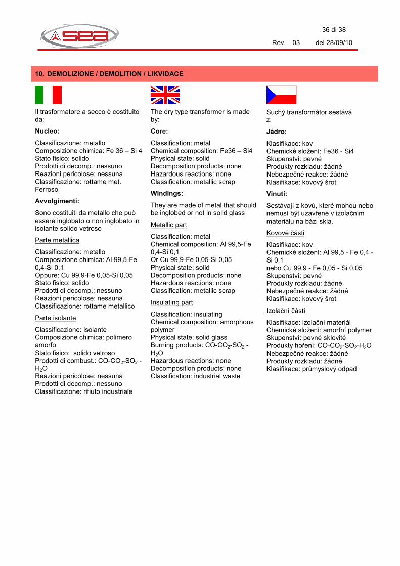
Il trasformatore a secco è costituito da:
Nucleo:
Classificazione: metallo Composizione chimica: Fe 36 – Si 4 Stato fisico: solido Prodotti di decomp.: nessuno Reazioni pericolose: nessuna Classificazione: rottame met. Ferroso
Avvolgimenti:
Sono costituiti da metallo che può essere inglobato o non inglobato in isolante solido vetroso
Parte metallica
Classificazione: metallo Composizione chimica: Al 99,5-Fe 0,4-Si 0,1 Oppure: Cu 99,9-Fe 0,05-Si 0,05 Stato fisico: solido Prodotti di decomp.: nessuno Reazioni pericolose: nessuna Classificazione: rottame metallico
Parte isolante
Classificazione: isolante Composizione chimica: polimero amorfo Stato fisico: solido vetroso Prodotti di combust.: CO-CO2-SO2 -H2O Reazioni pericolose: nessuna Prodotti di decomp.: nessuno Classificazione: rifiuto industriale
The dry type transformer is made by:
Core:
Classification: metal Chemical composition: Fe36 – Si4 Physical state: solid Decomposition products: none Hazardous reactions: none Classification: metallic scrap
Windings:
They are made of metal that should be inglobed or not in solid glass
Metallic part
Classification: metal Chemical composition: Al 99,5-Fe 0,4-Si 0,1 Or Cu 99,9-Fe 0,05-Si 0,05 Physical state: solid Decomposition products: none Hazardous reactions: none Classification: metallic scrap
Insulating part
Classification: insulating Chemical composition: amorphous polymer Physical state: solid glass Burning products: CO-CO2-SO2 -H2O Hazardous reactions: none Decomposition products: none Classification: industrial waste
Suchý transformátor sestává z:
Jádro:
Klasifikace: kov Chemické složení: Fe36 - Si4 Skupenství: pevné Produkty rozkladu: žádné Nebezpečné reakce: žádné Klasifikace: kovový šrot
Vinutí:
Sestávají z kovů, které mohou nebo nemusí být uzavřené v izolačním materiálu na bázi skla.
Kovové části
Klasifikace: kov Chemické složení: Al 99,5 - Fe 0,4 - Si 0,1 nebo Cu 99,9 - Fe 0,05 - Si 0,05 Skupenství: pevné Produkty rozkladu: žádné Nebezpečné reakce: žádné Klasifikace: kovový šrot
Izolační části
Klasifikace: izolační materiál Chemické složení: amorfní polymer Skupenství: pevné sklovité Produkty hoření: CO-CO2-SO2-H2O Nebezpečné reakce: žádné Produkty rozkladu: žádné Klasifikace: průmyslový odpad

37 di 38
Rev. 03 del 28/09/10
11. NOTE / NOTES / POZNÁMKY
In caso di richiesta da parte del Cliente S.E.A. S.p.A. è in grado di fornire le Schede di Sicurezza delle sostanze utilizzate.
In case the client requires it, S.E.A. S.p.A. can supply the Safety Data Sheets of the substances used.
V případě požadavku zákazníka může S.E.A. S.p.A. dodat bezpečnostní listy použitých materiálů.
Prima di effettuare qualsiasi operazione assicurarsi che sul luogo di lavoro e/o all’interno dell’armadio l’illuminazione sia adeguata: l’illuminazione sul luogo di lavoro deve essere sufficiente a consentire all’operatore di effettuare le manovre e la visione dei parametri elettrici (lettura strumenti, indicatori, allarmi, etc..) in caso contrario munirsi di dispositivi di illuminazione aggiuntiva.
Before starting every kind of job, make sure that the lighting is adequate: the lighting must be enough to permit to the operator to effect the operations and to see the electric parameters (reading of instruments, indicators, alarms, etc.). If the lighting is not enough use extra lighting.
Před zahájením jakékoli práce se ujistěte, zda je dostatečně osvětleno pracoviště. Osvětlení pracoviště musí být dostatečné, aby pracovník mohl provádět činnosti a sledovat elektrické parametry (odečet přístrojů, ukazatelů, výstrahy atd.). Nedostačuje-li osvětlení, použijte dodatečné osvětlení.
Prima della messa in servizio del trasformatore, l’utilizzatore DEVE leggere le istruzioni riportate nel Manuale d’uso e manutenzione.
Qualsiasi intervento sul trasformatore deve essere effettuato in sicurezza, secondo le istruzioni presenti nel Manuale d’uso e manutenzione da Personale Qualificato.
Before the start up of the transformer, the user MUST read the instructions written in the Usage and Maintenance Manual.
Every intervention performed on the transformer must be done in safety conditions, according to the instructions given in the Usage and Maintenance by Qualified Staff.
Před uvedením transformátoru do provozu MUSÍ uživatel přečíst pokyny v návodu pro instalaci, provoz a údržbu.
Jakýkoli zásah na transformátoru musí být proveden v bezpečných podmínkách podle pokynů v této příručce a kvalifikovanými pracovníky.
ATTENZIONE!
È cura del cliente provvedere alla protezione del trasformatore da eventuali sovratensioni tramite utilizzo di dispositivi idonei.
WARNING!
It is under client responsibility to protect the transformer from over voltages (if any) by using suitable instruments.
UPOZORNĚNÍ!
Zákazník odpovídá za ochranu transformátoru před případnými přepětími vhodným zařízením.

38 di 38
Rev. 03 del 28/09/10
Per tutte le operazioni di montaggio, smontaggio, collegamento, manutenzione, etc., utilizzare strumentazione idonea e dimensionata secondo normativa vigente.
During all the operations of mounting, dismounting, connection, maintenance, etc., always use adequate instruments dimensioned according to present norms.
Při montáži, demontáži, připojení, údržbě atd. používejte vždy vhodné vybavení, dimenzované podle platných předpisů.
S.E.A. S.p.A. declina ogni responsabilità per qualsiasi danno causato a persone, al trasformatore, o all’impianto, in seguito ad interventi effettuati da parte di personale non adeguatamente istruito o avvertito.
S.E.A. S.p.A. declines all responsibility for each damage caused to people, to transformer, or to the plant, caused by interventions made by not trained or warned staff.
S.E.A. S.p.A. odmítá jakoukoli zodpovědnost za škody na zdraví, na transformátoru nebo zařízení, zapříčiněné jednáním nevyškolených nebo nepoučených pracovníků.
12. CONCLUSIONE / CONCLUSION / ZÁVĚR
Vi preghiamo di segnalarci eventuali errori e/o incompletezze di questo manuale. Saremo ben lieti di tener conto dei Vostri consigli e delle Vostre segnalazioni nella prossima stesura.
Please let us know if there are any mistakes or oversights in this manual. We look forward to receiving your remarks and using them to update future editions.
Sdělte nám prosím případné chyby nebo nedostatky této příručky. Vaše podněty a připomínky vezmeme v úvahu při příštím vydání.
13. COME CONTATTARCI / HOW TO CONTACT US / KONTAKTUJTE NÁS
Per ogni dubbio, precisazione o ulteriore informazione sui nostri prodotti, potete rivolgervi al nostro Servizio Commerciale o Servizio Tecnico. I recapiti sono i seguenti:
In case of doubt or if you need more information about SEA products or our production range, do not hesitate to contact our Sales Dept. or Technical Dept. Our full address is indicated below:
V případě pochybností, dotazů nebo jiných informací se prosím obraťte na naše obchodní nebo technické oddělení. Kontaktní údaje jsou uvedeny níže.
Tel.: +39 0444 482100
Fax: +39 0444 482519
Indirizzo / Address / Adresa: Via L. Da Vinci, 14 - Tezze di Arzignano – VI - (ITALY)
E-mail: [email protected]
Web: http://www.seatrasformatori.it
Assistenza / Assistance / Podpora: ITA: http://www.seatrasformatori.it/assistenza
ENG: http://www.seatrasformatori.it/service
V ČR zastupuje: Power-Energo, s.r.o. Pod Pekárnami 245/10 tel. +420 296 642 197 190 00 Praha 9 www.power-energo.cz