Embed Size (px)
Citation preview
JK NAVASSA-5
5-Band Yagi (20M/17M/15M/12M/10M)
Optional 6M Add-on Kit Available
72 Grays Bridge Road, Unit D, Brookfield, CT 06804 ▪ 475.289.2222 (TEL) ▪ 845.279.5526 (FAX) ▪ [email protected]
Last Updated: Summer 2019
1
JK Antennas Limited Warranty and Liability
JK Antennas (“Manufacturer”) warrants to the original purchaser that this product will be free from defects in material, and workmanship for a period of one (1) year from the date of purchase. The determination of whether any part or parts will be covered by this limited warranty and whether any part or parts will be repaired, replaced or refunded will be solely determined by JK Antennas. Such determination will be made following evaluation of claim of alleged defect and subject to evaluation of possible misuse, abuse, unauthorized modifications, extreme weather conditions or improper installation. This warranty does not cover delivery, transportation, installation or any other costs that may be incurred from any defect.
The purchaser, final customer, installer and user of these products individually and collectively acknowledge that these products can cause injury or death and individually and collectively accept full responsibility and liability for any and all personal and property damage (direct, indirect and punitive) caused during installation and subsequent use.
Copyright Notice
This publication is Copyright © 2019 by JK Antennas. All rights reserved.
No part of this publication or addendum or attachments may be reproduced, stored in a retrieval system or transmitted in any form or by any means, electronic, mechanical, photocopying, recording or otherwise, without prior permission of JK Antennas.
WARNINGS
Installation of this antenna near power lines is dangerous. Contact with any high voltage power lines could result in electric shock or loss of life. Do not install this antenna where there is any possibility that the antenna or any part of the supporting structure could come in contact with power lines.
Also ensure that no persons or pets can come in any contact with the antenna after it is installed. Dangerous voltages can exist on the antenna when it is in operation and no part of the system is insulated to prevent shock.
Consult with FCC OET Bulletin 65 to properly evaluate whether the chosen installation site for this antenna will comply with the FCC guidelines for human exposure limits to radio frequency electro-magnetic fields.
This antenna structure is not designed to be used as a support structure. No persons or objects should be supported by or suspended from the antenna structure at any time.
Because most antenna systems are installed at high heights, the installed location must take into account that falling debris may pose a hazard to humans, animals and property on the ground below.
Be aware of and follow all local codes and ordinances when installing this antenna.
2
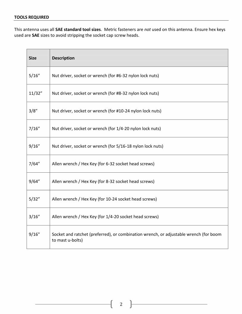
TOOLS REQUIRED
This antenna uses all SAE standard tool sizes. Metric fasteners are not used on this antenna. Ensure hex keys used are SAE sizes to avoid stripping the socket cap screw heads.
Size
Description
5/16”
Nut driver, socket or wrench (for #6-32 nylon lock nuts)
11/32”
Nut driver, socket or wrench (for #8-32 nylon lock nuts)
3/8”
Nut driver, socket or wrench (for #10-24 nylon lock nuts)
7/16”
Nut driver, socket or wrench (for 1/4-20 nylon lock nuts)
9/16”
Nut driver, socket or wrench (for 5/16-18 nylon lock nuts)
7/64”
Allen wrench / Hex Key (for 6-32 socket head screws)
9/64”
Allen wrench / Hex Key (for 8-32 socket head screws)
5/32”
Allen wrench / Hex Key (for 10-24 socket head screws)
3/16”
Allen wrench / Hex Key (for 1/4-20 socket head screws)
9/16"
Socket and ratchet (preferred), or combination wrench, or adjustable wrench (for boom to mast u-bolts)
3
ASSEMBLY GUIDELINES
1. Open the boxes and lay out the elements, hardware kits and parts 2. Using the parts list at the end this document, check to make sure all tubing, hardware kits and parts
are included (extra numbers of bolts, screws, nuts and washers are included) 3. The use of Penetrox or Noalox or any other Anti-seize/Anti-Oxidant compound is HIGHLY recommended
during installation of this antenna. Use a drop or 2 of this anti-seize paste on all screws before fastening. This will prevent the stainless-steel hardware from accidently locking up. Also a drop or two of the anti-oxidant paste on the element transitions will prevent corrosion in the joints as well ensure long lasting electrical performance.
The document has been separated into different assembly sections based on the packaged hardware kits. While it is recommended to assemble in the order presented, please adjust as needed based on your working conditions and assembly area.
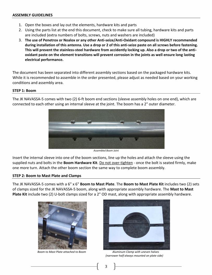
STEP 1: Boom
The JK NAVASSA-5 comes with two (2) 6-ft boom end sections (sleeve assembly holes on one end), which are connected to each other using an internal sleeve at the joint. The boom has a 2" outer diameter.
Assembled Boom Joint
Insert the internal sleeve into one of the boom sections, line up the holes and attach the sleeve using the supplied nuts and bolts in the Boom Hardware Kit. Do not over-tighten - once the bolt is seated firmly, make one more turn. Attach the other boom section the same way to complete boom assembly.
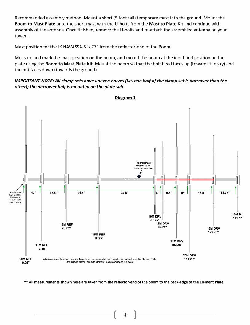
STEP 2: Boom to Mast Plate and Clamps
The JK NAVASSA-5 comes with a 6" x 6" Boom to Mast Plate. The Boom to Mast Plate Kit includes two (2) sets of clamps sized for the JK NAVASSA-5 boom, along with appropriate assembly hardware. The Mast to Mast Plate Kit include two (2) U-bolt clamps sized for a 2" OD mast, along with appropriate assembly hardware.
Boom to Mast Plate attached to Boom Aluminum Clamp with uneven halves (narrower half always mounted on plate side)
4
Recommended assembly method: Mount a short (5 foot tall) temporary mast into the ground. Mount the Boom to Mast Plate onto the short mast with the U-bolts from the Mast to Plate Kit and continue with assembly of the antenna. Once finished, remove the U-bolts and re-attach the assembled antenna on your tower.
Mast position for the JK NAVASSA-5 is 77” from the reflector-end of the Boom.
Measure and mark the mast position on the boom, and mount the boom at the identified position on the plate using the Boom to Mast Plate Kit. Mount the boom so that the bolt head faces up (towards the sky) and the nut faces down (towards the ground).
IMPORTANT NOTE: All clamp sets have uneven halves (i.e. one half of the clamp set is narrower than the other); the narrower half is mounted on the plate side.
Diagram 1
** All measurements shown here are taken from the reflector-end of the boom to the back-edge of the Element Plate.
5
STEP 3: Element Assembly
If you are also installing the optional 6M ADD-ON KIT, please read the 6M ADD-ON Kit instructions on page 12 before assembling the 15M DRV and 10MD1 elements.
The elements of the JK NAVASSA-5 are comprised of various telescoping sizes of aluminum tubing attached to each other using counterbored holes to create a mechanically and electrically superior joint. Elements are designed to be mounted on the underside of the boom, following the location and measurements of Diagram 1 on the previous page.
First assemble the Driven Element Center Sections (STEP 3a). Then, gather the Driven Element and other element center sections, and follow the instructions in the Element to Element Plate (STEP 3b) and the Boom to Element Plate (STEP 3c) sections coming after. Once all the center sections are mounted on the boom at the identified locations, the rest of the element tapers will be assembled off the antenna (STEP 3d).
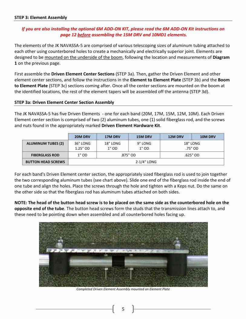
STEP 3a: Driven Element Center Section Assembly
The JK NAVASSA-5 has five Driven Elements - one for each band (20M, 17M, 15M, 12M, 10M). Each Driven Element center section is comprised of two (2) aluminum tubes, one (1) solid fiberglass rod, and the screws and nuts found in the appropriately marked Driven Element Hardware Kit.
20M DRV 17M DRV 15M DRV 12M DRV 10M DRV
ALUMINUM TUBES (2) 36" LONG 1.25" OD
18" LONG 1" OD
9" LONG 1" OD
18" LONG .75" OD
FIBERGLASS ROD 1" OD .875" OD .625" OD
BUTTON HEAD SCREWS 2-1/4" LONG
For each band's Driven Element center section, the appropriately sized fiberglass rod is used to join together the two corresponding aluminum tubes (see chart above). Slide one end of the fiberglass rod inside the end of one tube and align the holes. Place the screws through the hole and tighten with a Keps nut. Do the same on the other side so that the fiberglass rod has aluminum tubes attached on both sides.
NOTE: The head of the button head screw is to be placed on the same side as the counterbored hole on the opposite end of the tube. The button head screws form the studs that the transmission lines attach to, and these need to be pointing down when assembled and all counterbored holes facing up.
Completed Driven Element Assembly mounted on Element Plate
6
The aluminum tube/fiberglass rod assemblies of the driven element center sections can be mounted on the element plates and then onto the boom the same as the other element sections.
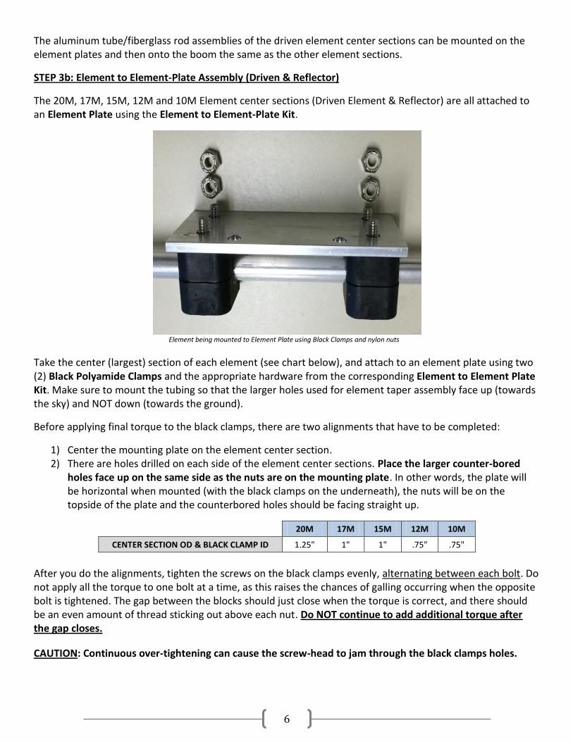
STEP 3b: Element to Element-Plate Assembly (Driven & Reflector)
The 20M, 17M, 15M, 12M and 10M Element center sections (Driven Element & Reflector) are all attached to an Element Plate using the Element to Element-Plate Kit.
Element being mounted to Element Plate using Black Clamps and nylon nuts
Take the center (largest) section of each element (see chart below), and attach to an element plate using two (2) Black Polyamide Clamps and the appropriate hardware from the corresponding Element to Element Plate Kit. Make sure to mount the tubing so that the larger holes used for element taper assembly face up (towards the sky) and NOT down (towards the ground).
Before applying final torque to the black clamps, there are two alignments that have to be completed:
1) Center the mounting plate on the element center section. 2) There are holes drilled on each side of the element center sections. Place the larger counter-bored
holes face up on the same side as the nuts are on the mounting plate. In other words, the plate will be horizontal when mounted (with the black clamps on the underneath), the nuts will be on the topside of the plate and the counterbored holes should be facing straight up.
20M 17M 15M 12M 10M
CENTER SECTION OD & BLACK CLAMP ID 1.25" 1" 1" .75" .75"
After you do the alignments, tighten the screws on the black clamps evenly, alternating between each bolt. Do not apply all the torque to one bolt at a time, as this raises the chances of galling occurring when the opposite bolt is tightened. The gap between the blocks should just close when the torque is correct, and there should be an even amount of thread sticking out above each nut. Do NOT continue to add additional torque after the gap closes.
CAUTION: Continuous over-tightening can cause the screw-head to jam through the black clamps holes.
7
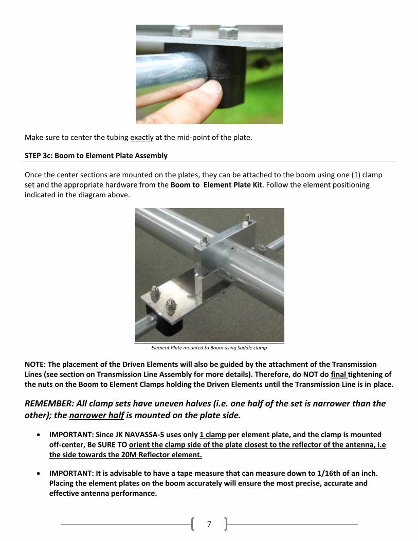
Make sure to center the tubing exactly at the mid-point of the plate.
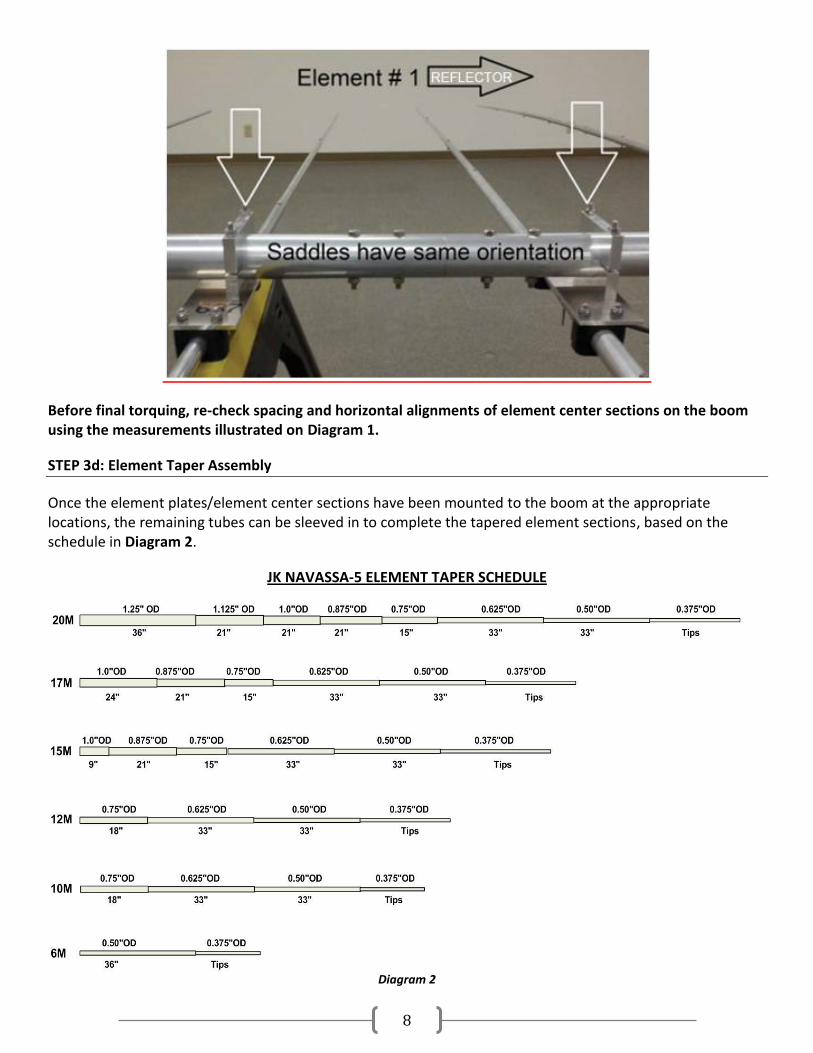
STEP 3c: Boom to Element Plate Assembly
Once the center sections are mounted on the plates, they can be attached to the boom using one (1) clamp set and the appropriate hardware from the Boom to Element Plate Kit. Follow the element positioning indicated in the diagram above.
Element Plate mounted to Boom using Saddle clamp
NOTE: The placement of the Driven Elements will also be guided by the attachment of the Transmission Lines (see section on Transmission Line Assembly for more details). Therefore, do NOT do final tightening of the nuts on the Boom to Element Clamps holding the Driven Elements until the Transmission Line is in place.
REMEMBER: All clamp sets have uneven halves (i.e. one half of the set is narrower than the other); the narrower half is mounted on the plate side.
IMPORTANT: Since JK NAVASSA-5 uses only 1 clamp per element plate, and the clamp is mounted off-center, Be SURE TO orient the clamp side of the plate closest to the reflector of the antenna, i.e the side towards the 20M Reflector element.
IMPORTANT: It is advisable to have a tape measure that can measure down to 1/16th of an inch. Placing the element plates on the boom accurately will ensure the most precise, accurate and effective antenna performance.
8
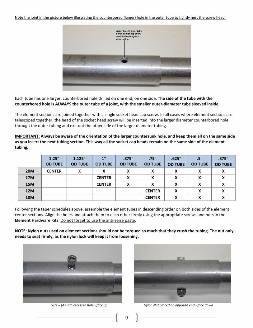
Before final torquing, re-check spacing and horizontal alignments of element center sections on the boom using the measurements illustrated on Diagram 1.
STEP 3d: Element Taper Assembly
Once the element plates/element center sections have been mounted to the boom at the appropriate locations, the remaining tubes can be sleeved in to complete the tapered element sections, based on the schedule in Diagram 2.
JK NAVASSA-5 ELEMENT TAPER SCHEDULE
Diagram 2
9
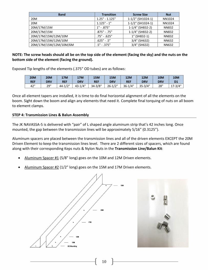
Note the joint in the picture below illustrating the counterbored (larger) hole in the outer tube to tightly nest the screw head.
Each tube has one larger, counterbored hole drilled on one end, on one side. The side of the tube with the counterbored hole is ALWAYS the outer tube of a joint, with the smaller outer-diameter tube sleeved inside.
The element sections are joined together with a single socket head cap screw. In all cases where element sections are telescoped together, the head of the socket head screw will be inserted into the larger diameter counterbored hole through the outer tubing and exit out the other side of the larger diameter tubing.
IMPORTANT: Always be aware of the orientation of the larger countersunk hole, and keep them all on the same side as you insert the next tubing section. This way all the socket cap heads remain on the same side of the element tubing.
1.25" OD TUBE
1.125" OD TUBE
1" OD TUBE
.875" OD TUBE
.75" OD TUBE
.625"
OD TUBE
.5" OD TUBE
.375"
OD TUBE
20M CENTER X X X X X X X
17M CENTER X X X X X
15M CENTER X X X X X
12M CENTER X X X
10M CENTER X X X
Following the taper schedules above, assemble the element tubes in descending order on both sides of the element center sections. Align the holes and attach them to each other firmly using the appropriate screws and nuts in the Element Hardware Kits. Do not forget to use the anti-seize paste.
NOTE: Nylon nuts used on element sections should not be torqued so much that they crush the tubing. The nut only needs to seat firmly, as the nylon lock will keep it from loosening.
Screw fits into recessed hole - face up Nylon Nut placed on opposite end - face down
10
Band Transition Screw Size Nut
20M 1.25" - 1.125" 1-1/2" (SH1024-1) NN1024
20M 1.125" - 1" 1-1/2" (SH1024-1) NN1024
20M/17M/15M 1" - .875" 1-1/4" (SH832-2) NN832
20M/17M/15M .875" - .75" 1-1/4" (SH832-2) NN832
20M/17M/15M/12M/10M .75" - .625" 1" (SH832-1) NN832
20M/17M/15M/12M/10M .625” - .5” 3/4" (SH632) NN632
20M/17M/15M/12M/10M/6M .5" - .375" 3/4" (SH632) NN632
NOTE: The screw heads should all be on the top side of the element (facing the sky) and the nuts on the bottom side of the element (facing the ground).
Exposed Tip lengths of the elements (.375" OD tubes) are as follows:
20M REF
20M DRV
17M REF
17M DRV
15M REF
15M DRV
12M REF
12M DRV
10M DRV
10M D1
42" 29" 44-1/2" 43-1/4" 34-3/8" 26-1/2" 36-1/4" 35-3/4" 28" 17-3/4"
Once all element tapers are installed, it is time to do final horizontal alignment of all the elements on the boom. Sight down the boom and align any elements that need it. Complete final torquing of nuts on all boom to element clamps.
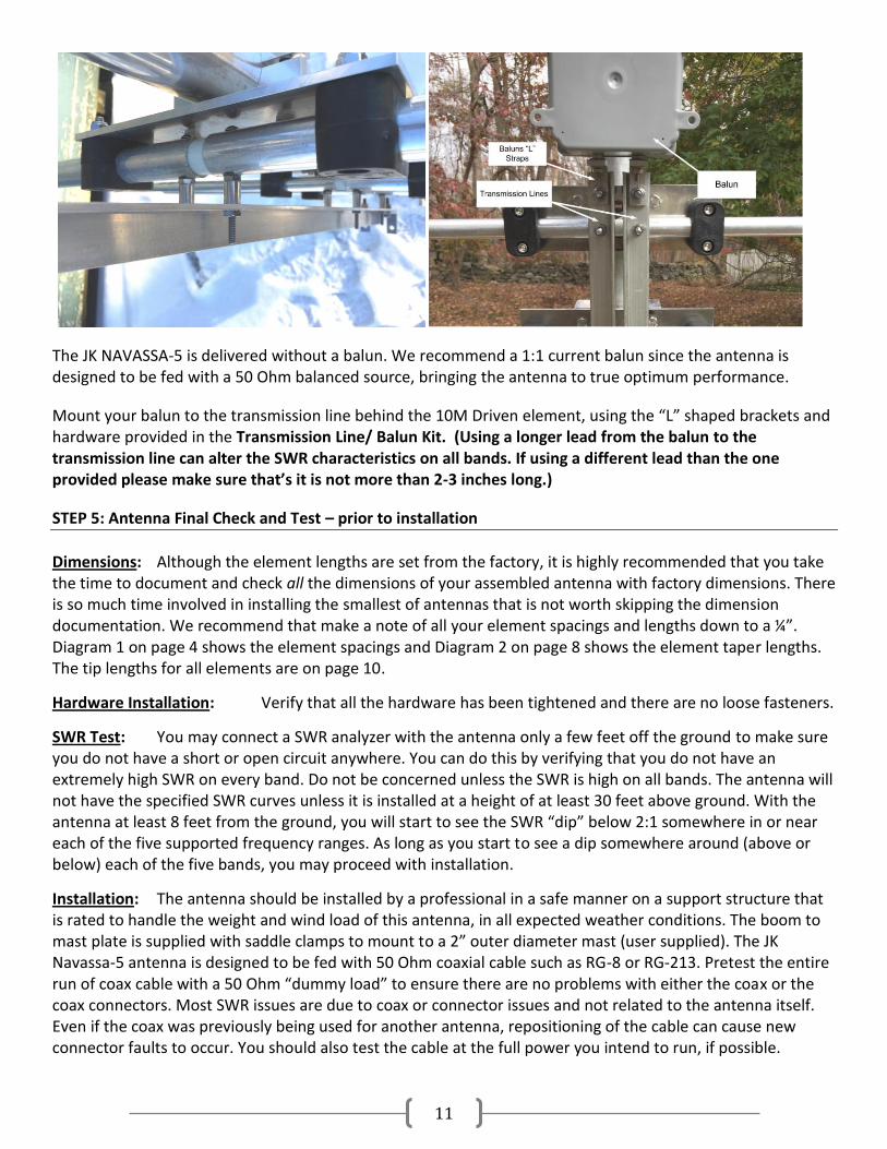
STEP 4: Transmission Lines & Balun Assembly
The JK NAVASSA-5 is delivered with “pair” of L shaped angle aluminum strip that’s 42 inches long. Once mounted, the gap between the transmission lines will be approximately 5/16” (0.3125”).
Aluminum spacers are placed between the transmission lines and all of the driven elements EXCEPT the 20M Driven Element to keep the transmission lines level. There are 2 different sizes of spacers, which are found along with their corresponding Keps nuts & Nylon Nuts in the Transmission Line/Balun Kit:
Aluminum Spacer #1 (5/8" long) goes on the 10M and 12M Driven elements.
Aluminum Spacer #2 (1/2" long) goes on the 15M and 17M Driven elements.
11
The JK NAVASSA-5 is delivered without a balun. We recommend a 1:1 current balun since the antenna is designed to be fed with a 50 Ohm balanced source, bringing the antenna to true optimum performance.
Mount your balun to the transmission line behind the 10M Driven element, using the “L” shaped brackets and hardware provided in the Transmission Line/ Balun Kit. (Using a longer lead from the balun to the transmission line can alter the SWR characteristics on all bands. If using a different lead than the one provided please make sure that’s it is not more than 2-3 inches long.)
STEP 5: Antenna Final Check and Test – prior to installation
Dimensions: Although the element lengths are set from the factory, it is highly recommended that you take the time to document and check all the dimensions of your assembled antenna with factory dimensions. There is so much time involved in installing the smallest of antennas that is not worth skipping the dimension documentation. We recommend that make a note of all your element spacings and lengths down to a ¼”. Diagram 1 on page 4 shows the element spacings and Diagram 2 on page 8 shows the element taper lengths. The tip lengths for all elements are on page 10.
Hardware Installation: Verify that all the hardware has been tightened and there are no loose fasteners.
SWR Test: You may connect a SWR analyzer with the antenna only a few feet off the ground to make sure you do not have a short or open circuit anywhere. You can do this by verifying that you do not have an extremely high SWR on every band. Do not be concerned unless the SWR is high on all bands. The antenna will not have the specified SWR curves unless it is installed at a height of at least 30 feet above ground. With the antenna at least 8 feet from the ground, you will start to see the SWR “dip” below 2:1 somewhere in or near each of the five supported frequency ranges. As long as you start to see a dip somewhere around (above or below) each of the five bands, you may proceed with installation.
Installation: The antenna should be installed by a professional in a safe manner on a support structure that is rated to handle the weight and wind load of this antenna, in all expected weather conditions. The boom to mast plate is supplied with saddle clamps to mount to a 2” outer diameter mast (user supplied). The JK Navassa-5 antenna is designed to be fed with 50 Ohm coaxial cable such as RG-8 or RG-213. Pretest the entire run of coax cable with a 50 Ohm “dummy load” to ensure there are no problems with either the coax or the coax connectors. Most SWR issues are due to coax or connector issues and not related to the antenna itself. Even if the coax was previously being used for another antenna, repositioning of the cable can cause new connector faults to occur. You should also test the cable at the full power you intend to run, if possible.
12
Surrounding metallic objects (other antennas, guy wires, etc.) can affect the performance of the antenna. If the antenna is not interacting with anything, you can expect the specified SWR curve, gain and front to rear performance. There are no user adjustments necessary for this antenna - any SWR issues indicate a coax and/or connector fault, or interaction of this antenna with another metallic object and those situations must be corrected.
The reference SWR curves, both design and factory measured, are available on our website at: http://jkantennas.com /navassa-5-data.html
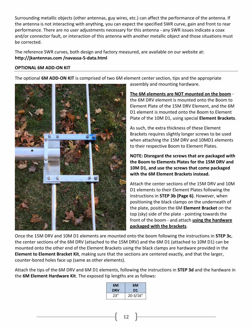
OPTIONAL 6M ADD-ON KIT
The optional 6M ADD-ON KIT is comprised of two 6M element center section, tips and the appropriate assembly and mounting hardware.
The 6M elements are NOT mounted on the boom - the 6M DRV element is mounted onto the Boom to Element Plate of the 15M DRV Element, and the 6M D1 element is mounted onto the Boom to Element Plate of the 10M D1, using special Element Brackets.
As such, the extra thickness of these Element Brackets requires slightly longer screws to be used when attaching the 15M DRV and 10MD1 elements to their respective Boom to Element Plates.
NOTE: Disregard the screws that are packaged with the Boom to Elements Plates for the 15M DRV and 10M D1, and use the screws that come packaged with the 6M Element Brackets instead.
Attach the center sections of the 15M DRV and 10M D1 elements to their Element Plates following the instructions in STEP 3b (Page 6). However, when positioning the black clamps on the underneath of the plate, position the 6M Element Bracket on the top (sky) side of the plate - pointing towards the front of the boom - and attach using the hardware packaged with the brackets.
Once the 15M DRV and 10M D1 elements are mounted onto the boom following the instructions in STEP 3c, the center sections of the 6M DRV (attached to the 15M DRV) and the 6M D1 (attached to 10M D1) can be mounted onto the other end of the Element Brackets using the black clamps are hardware provided in the Element to Element Bracket Kit, making sure that the sections are centered exactly, and that the larger, counter-bored holes face up (same as other elements).
Attach the tips of the 6M DRV and 6M D1 elements, following the instructions in STEP 3d and the hardware in the 6M Element Hardware Kit. The exposed tip lengths are as follows:
6M DRV
6M D1
23" 20-3/16"
13
JK NAVASSA-5 PARTS LIST
BOOM TO MAST ASSEMBLY
BMP-3
6" x 6" Mast Plate 1
Boom to Mast Plate
BMC2.0-3i-5/8 2" Boom to Plate clamp 2
HH51618 3-1/2" Hex Head Screw 5/16-18 4+1
NN51618
Nylon Nut 5/16-18 4+1
Mast to Mast Plate
U-Bolt + Nuts 2" Mast to Mast Plate clamp 2
BOOM ASSEMBLY
AT2.0 Boom SS 6 ft Boom End 2
AT1.875 Sleeve
Boom Sleeve 1
Boom Hardware
HH51618 2-1/2" Hex Head Screw 5/16-18 4+1
NN51618
Nylon Nut 5/16-18 4+1
BOOM TO 20M ELEMENT ASSEMBLIES
BEP-3
9" x 3" Element Plate for 20M 2
Element to Element Plate (two 20M Elements)
BC1.25
1-1/4" Black Polyamide clamps 4
SH1420 2-3/4" Socket Head Screw 1/4-20 8+2
NN1420
Nylon Nut 1/4-20 8+2
Boom to Element Plate (two 20M Elements)
BEC2.0-3i-5/8 2" Boom to Element Plate clamp 2
HH51618 3-1/2" Hex Head Screw 5/16-18 4+1
NN51618
Nylon Nut 5/16-18 4+1
BOOM TO 17M/15M/12M/10M ELEMENT ASSEMBLIES
BEP-4
8-1/4" x 2-1/2" Element Plate for 17M/15M/12M/10M 8
Element to Element Plate (two 17M and two 15M Elements)
BC1.0
1" Black Polyamide clamps 8
SH1420 1-3/4" Socket Head Screw 1/4-20 16+2
NN1420
Nylon Nut 1/4-20 16+2
Element to Element Plate (two 12M and two 10M Elements)
BC.75
3/4" Black Polyamide clamps 8
SH1420 1-3/4" Socket Head Screw 1/4-20 16+2
NN1420
Nylon Nut 1/4-20 16+2
Boom to Element Plate (two 17M Elements, two 15M Elements, two 12M Elements, two 10M Elements)
BEC2.0-3i
2" Boom to Element Plate clamp 8
HH1420 3-1/2" Hex Head Screw 1/4-20 16+2
NN1420
Nylon Nut 1/4-20 16+2
14
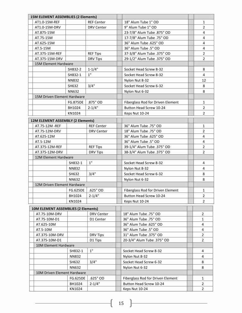
20M ELEMENT ASSEMBLIES (2 Elements)
AT1.25-20M-REF
REF Center 72" Alum Tube 1.25" OD 1
AT1.25-20M-DRV
DRV Center 36" Alum Tube 1.25" OD 2
AT1.125-20M
23-7/8" Alum Tube 1.125" OD 4
AT1.125-D-20M
36" Alum Tube 1.125" OD - DOUBLER 1
AT1.0-20M
23-7/8" Alum Tube 1.0" OD 4
AT.875-20M
23-7/8" Alum Tube .875" OD 4
AT.75-20M
17-7/8" Alum Tube .75" OD 4
AT.625-20M
36" Alum Tube .625" OD 4
AT.5-20M
36" Alum Tube .5" OD 4
AT.375-20M-REF
REF Tips 44-7/8" Alum Tube .375" OD 2
AT.375-20M-DRV
DRV Tips 31-7/8" Alum Tube .375" OD 2
20M Element Hardware
SH1024-1 1-1/2" Socket Head Screw 10-24 8
NN1024
Nylon Nut 10-24 8
SH832-2 1-1/4" Socket Head Screw 8-32 8
SH832-1 1" Socket Head Screw 8-32 4
NN832
Nylon Nut 8-32 12
SH632 3/4" Socket Head Screw 6-32 8
NN632
Nylon Nut 6-32 8
20M Driven Element Hardware
FG1.0DE 1" OD Fiberglass Rod for Driven Element 1
BH1024 2-1/4" Button Head Screw 10-24 2
KN1024
Keps Nut 10-24 2
17M ELEMENT ASSEMBLIES (2 Elements)
AT1.0-17M-REF
REF Center 48" Alum Tube 1" OD 1
AT1.0-17M-DRV
DRV Center 23-7/8" Alum Tube 1" OD 2
AT.875-17M
23-7/8" Alum Tube .875" OD 4
AT.75-17M
17-7/8" Alum Tube .75" OD 4
AT.625-17M
36" Alum Tube .625" OD 4
AT.5-17M
36" Alum Tube .5" OD 4
AT.375-17M-REF
REF Tips 47-1/2" Alum Tube .375" OD 2
AT.375-17M-DRV
DRV Tips 46-1/4" Alum Tube .375" OD 2
17M Element Hardware
SH832-2 1-1/4" Socket Head Screw 8-32 8
SH832-1 1" Socket Head Screw 8-32 4
NN832
Nylon Nut 8-32 12
SH632 3/4" Socket Head Screw 6-32 8
NN632
Nylon Nut 6-32 8
17M Driven Element Hardware
FG.875DE .875" OD Fiberglass Rod for Driven Element 1
BH1024 2-1/4" Button Head Screw 10-24 2
KN1024
Keps Nut 10-24 2
15
15M ELEMENT ASSEMBLIES (2 Elements)
AT1.0-15M-REF
REF Center 18" Alum Tube 1" OD 1
AT1.0-15M-DRV
DRV Center 9" Alum Tube 1" OD 2
AT.875-15M
23-7/8" Alum Tube .875" OD 4
AT.75-15M
17-7/8" Alum Tube .75" OD 4
AT.625-15M
36" Alum Tube .625" OD 4
AT.5-15M
36" Alum Tube .5" OD 4
AT.375-15M-REF
REF Tips 37-3/8" Alum Tube .375" OD 2
AT.375-15M-DRV
DRV Tips 29-1/2" Alum Tube .375" OD 2
15M Element Hardware
SH832-2 1-1/4" Socket Head Screw 8-32 8
SH832-1 1" Socket Head Screw 8-32 4
NN832
Nylon Nut 8-32 12
SH632 3/4" Socket Head Screw 6-32 8
NN632
Nylon Nut 6-32 8
15M Driven Element Hardware
FG.875DE .875" OD Fiberglass Rod for Driven Element 1
BH1024 2-1/4" Button Head Screw 10-24 2
KN1024
Keps Nut 10-24 2
12M ELEMENT ASSEMBLY (2 Elements)
AT.75-12M -REF
REF Center 36" Alum Tube .75" OD 1
AT.75-12M-DRV
DRV Center 18" Alum Tube .75" OD 2
AT.625-12M
36" Alum Tube .625" OD 4
AT.5-12M
36" Alum Tube .5" OD 4
AT.375-12M-REF
REF Tips 39-1/4" Alum Tube .375" OD 2
AT.375-12M-DRV
DRV Tips 38-3/4" Alum Tube .375" OD 2
12M Element Hardware
SH832-1 1" Socket Head Screw 8-32 4
NN832
Nylon Nut 8-32 4
SH632 3/4" Socket Head Screw 6-32 8
NN632
Nylon Nut 6-32 8
12M Driven Element Hardware
FG.625DE .625" OD Fiberglass Rod for Driven Element 1
BH1024 2-1/4" Button Head Screw 10-24 2
KN1024
Keps Nut 10-24 2
10M ELEMENT ASSEMBLIES (2 Elements)
AT.75-10M-DRV
DRV Center 18" Alum Tube .75" OD 2
AT.75-10M-D1
D1 Center 36" Alum Tube .75" OD 1
AT.625-10M
36" Alum Tube .625" OD 4
AT.5-10M
36" Alum Tube .5" OD 4
AT.375-10M-DRV
DRV Tips 31" Alum Tube .375" OD 2
AT.375-10M-D1
D1 Tips 20-3/4" Alum Tube .375" OD 2
10M Element Hardware
SH832-1 1" Socket Head Screw 8-32 4
NN832
Nylon Nut 8-32 4
SH632 3/4" Socket Head Screw 6-32 8
NN632
Nylon Nut 6-32 8
10M Driven Element Hardware
FG.625DE .625" OD Fiberglass Rod for Driven Element 1
BH1024 2-1/4" Button Head Screw 10-24 2
KN1024
Keps Nut 10-24 2
16
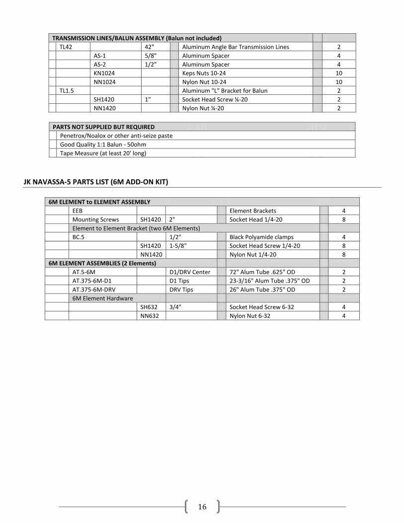
TRANSMISSION LINES/BALUN ASSEMBLY (Balun not included)
TL42
42" Aluminum Angle Bar Transmission Lines 2
AS-1 5/8" Aluminum Spacer 4
AS-2 1/2" Aluminum Spacer 4
KN1024
Keps Nuts 10-24 10
NN1024 Nylon Nut 10-24 10
TL1.5
Aluminum "L" Bracket for Balun 2
SH1420 1" Socket Head Screw ¼-20 2
NN1420
Nylon Nut ¼-20 2
PARTS NOT SUPPLIED BUT REQUIRED
Penetrox/Noalox or other anti-seize paste
Good Quality 1:1 Balun - 50ohm
Tape Measure (at least 20' long)
JK NAVASSA-5 PARTS LIST (6M ADD-ON KIT)
6M ELEMENT to ELEMENT ASSEMBLY
EEB
Element Brackets 4
Mounting Screws SH1420 2" Socket Head 1/4-20 8
Element to Element Bracket (two 6M Elements)
BC.5
1/2" Black Polyamide clamps 4
SH1420 1-5/8" Socket Head Screw 1/4-20 8
NN1420
Nylon Nut 1/4-20 8
6M ELEMENT ASSEMBLIES (2 Elements)
AT.5-6M
D1/DRV Center 72" Alum Tube .625" OD 2
AT.375-6M-D1
D1 Tips 23-3/16" Alum Tube .375" OD 2
AT.375-6M-DRV
DRV Tips 26" Alum Tube .375" OD 2
6M Element Hardware
SH632 3/4" Socket Head Screw 6-32 4
NN632
Nylon Nut 6-32 4