Embed Size (px)
Citation preview

地球に優しい緑の
発電機
ISO-14001
JQA-EM4858
ISO-9001
JQA-1232http://www.n-sharyo.co.jp/
NES SERIESDiesel Engine Generator
Certified Certified
80, Ryucho, Narumi-cho, Midori-ku, Nagoya, 458-8502, JapanTel: +81-52-623-3529 Fax: +81-52-623-4349
Manufacturer
Distributor
CAT.No.142B (2014-1)
URL Due to company policy of continuousdevelopment and improvement, NIPPONSHARYO reserves the right to changedesigns and specifications without notice.
Reliable technology, further evolution
Earth-friendly green generators
n_sharyo_Catalog_eng.indd 1 14.11.21 6:36:11 PM

1
NES SERIES
Environment-friendly green generator
High performance and high quality chosen by professionalsUseful and safe equipment and structure
Well-received NISSHA generatorsWide-ranging options
Usefuland safe
Environment
Excellent reputation
Options
High performance,high quality
The history and progress of diesel generator sets cannot be told without Nippon Sharyo, Ltd. We have defined the times by launching various power production facilities with new innovative concepts. We continue to contribute to the environment and ergonomics through improving our products.
Paving the way to the futurePowerfu l and Ear th-Fr iendly GeneratorAs a manufacturer of foundation construction equipment, Nippon Sharyo delivers leading-edge portable generators designed considering environmental issues such as global warming, air pollution and noise, with many years of construction experience.
Environment-friendly
Super low noise levelLow noise design for environment-friendliness. The product line up NES25 – NES220 meets super low noise level.
Compact and light-weightThe body is small and light-weight, enabling easytransportation by truck and reducing transportation costs.
Oil guard as a standardAn oil guard is equipped as standard on all models thatconform to the Third Emission Regulation. This reducesground contamination from oil leakage.
Reduced fuel consumptionFuel consumption can be reduced by using an optional e-Pon, energy saving remote control and slowdown device.
Please consult Nippon Sharyo about selection beforehand.We will make suggestions according to your usage environment and load.
Note : For details, refer to the options table on pages 15 and 16.
n_sharyo_Catalog_eng.indd 2 14.11.21 6:36:12 PM

2
PRODUCT INFORMATION
High performance and High quality
High-quality power supply
Fuel air bleeding
Weather resistant coating
Tough and durable
High insulation
The FET-type AVR (Automatic Voltage Regulator) and high-performance damper winding provide high-quality power with a voltage regulation of ±0.5%. In addition to working well with general linear loads, the generator also works well with non-linear loads such as inverters.
NES25 – NES60,NES100TI, NES125TI
All models (except for the NES100El) are equipped with a dual voltage feature to select either 200V for general use and 400V for large-capacity equipment. The dual voltage feature meets the need for globalization since 400V loads are more common overseas. The voltage currently selected is shown by the voltage indicator.
The NES25 is provided with a three-phase/single phase three-wire independent terminal that enables simultaneous use.
When the start/stop switch is in the ON position, a fuel pumps operates to execute air bleeding, which is very useful when changing fuel filters (standard equipment on NES25TK – NES400TI and NES100El).
Electrodeposition and weather-resistant baking finish are used on all models, providing high resistance to corrosion.
NISSHA generators are known for toughness and durability. We continue to create products that satisfy our customers.
The alternator winding is coated with varnish using dripping impregnation and vacuum impregnation to provide high insulation performance.
Methods
Control Panel Control Panel
Example: NES45TY2 Example: NES150TI
New function
New function
New function
Dual voltage
Three-phase/single-phase three-wire simultaneous output
(switching not required)
200/220V or 400/440V
115/127V or 230/254V
U V W O
200/220V
100/110V 100/110V
Three-phase four-wire Single-phase three-wireSingle-phase
Three-phase
Simultaneous
Voltage Changeover Terminal Block
NES100EI, NES125EH, NES150 – NES800
Voltage Changeover Terminal Board
Voltage indicator
Note: Some of the above features are not included in some models.
200V/400VSetting
n_sharyo_Catalog_eng.indd 3 14.11.21 6:36:14 PM
3
PRODUCT INFORMATION
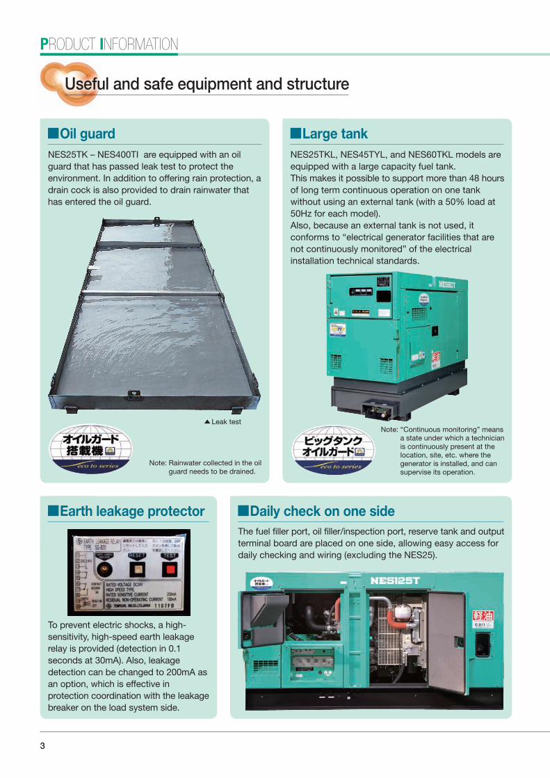
Useful and safe equipment and structure
Oil guard Large tankNES25TK – NES400TI are equipped with an oil guard that has passed leak test to protect the environment. In addition to offering rain protection, a drain cock is also provided to drain rainwater that has entered the oil guard.
NES25TKL, NES45TYL, and NES60TKL models are equipped with a large capacity fuel tank.This makes it possible to support more than 48 hours of long term continuous operation on one tank without using an external tank (with a 50% load at 50Hz for each model).Also, because an external tank is not used, it conforms to “electrical generator facilities that are not continuously monitored” of the electrical installation technical standards.
Earth leakage protector Daily check on one side
To prevent electric shocks, a high-sensitivity, high-speed earth leakage relay is provided (detection in 0.1 seconds at 30mA). Also, leakage detection can be changed to 200mA as an option, which is effective in protection coordination with the leakage breaker on the load system side.
The fuel filler port, oil filler/inspection port, reserve tank and output terminal board are placed on one side, allowing easy access for daily checking and wiring (excluding the NES25).
Leak test
Note: Rainwater collected in the oil guard needs to be drained.
Note: “Continuous monitoring” means a state under which a technician is continuously present at the location, site, etc. where the generator is installed, and can supervise its operation.
n_sharyo_Catalog_eng.indd 4 14.11.21 6:36:18 PM

4
Easy oil change Easy radiator flushing Fuel tank three-way cock
Certification
Oil can be changed quickly and easily without special tools. Maintenance time is saved and your hands keep clean (applies to NES25, NES45TY2, and NES60).
The front cover of the radiator is either a full-open type (NES25 to NES60) or hinged type (NES100 to NES800) to enable easy flushing of the radiator.
A single-lever, fuel tank changeover cock for switching between the internal and external tanks is provided to allow for long time operation. The cock is easy to operate and prevents mistakes switching. (Provided on NES25 to NES220, except NES25TKL, NES45TYL and NES60TKL.)
The specifications, registration and certification of government agencies and other organizations in Japan show the trust placed in NISSHA generators.
Construction equipment conforming to the Third Emission Regulation designated by MLIT (NES25TK – NES400TI)
Super low noise construction equipment designated by MLIT (NES25 – NES220)
Low noise construction equipment designated by MLIT (NES400 – NES800)
Oil guard integrated generator registered with NETIS by MLIT (NES25TK – NES400TI)
Portable generator certified by the Nippon Engine Generator Association (all models)
Note : Third Emission Gas Policy models
New IC monitorNew IC monitor checks the system formalfunction at all times before and during operation.
Item Enginestop
Breakertrip Lamp
Low oil pressure
High water temperature
Overspeed
Battery voltage failure
Non charge
Low fuel level
Oil guard *1
Diagnosis (ECU error) *2
Overcurrent
Earth leakage
Oil drain hose Three-way cock of fuel tank
Mon
itor
*1: Large tank models only (NES25TKL, NES45TYL, NES60TKL).*2: ECU models only (NES45 to NES400TI).
Note: Except machines equipped with second exhaust emission compliant engines and NES800SM.
Machines equipped with the Second Exhaust Emission engines (NES100EI – NES500EM)
Example: Control panel of NES100TI
n_sharyo_Catalog_eng.indd 5 14.11.21 6:36:21 PM

5
SPECIFICATIONS
Specifications
Item NES25TK NES25TKL NES45TY2 NES45TYL NES60TK NES60TKL NES100TI NES125TI NES150TI NES220TI NES400TIFrequency Hz 50 60 50 60 50 60 50 60 50 60 50 60 50 60 50 60 50 60 50 60 50 60
OutputkVA 20 25 20 25 37 45 37 45 50 60 50 60 80 100 100 125 125 150 200 220 350 400kW 16 20 16 20 29.6 36 29.6 36 40 48 40 48 64 80 80 100 100 120 160 176 280 320
200VVoltage V 200 220 200 220 200 220 200 220 200 220 200 220 200 220 200 220 200 220 200 220 200 220Current A 57.7 65.6 57.7 65.6 107 118 107 118 144 157 144 157 231 262 289 328 361 394 577 577 1010 1050
400VVoltage V 400 440 400 440 400 440 400 440 400 440 400 440 400 440 400 440 400 440 400 440 400 440Current A 28.9 32.8 28.9 32.8 53.4 59.0 53.4 59.0 72.2 78.7 72.2 78.7 115 131 144 164 180 197 289 289 505 525
100/200V Output *1
kVA 11.5 5.8 *7 14.4 7.2 *7 11.5 5.8 *7 14.4 7.2 *7 21.4 26.0 21.4 26.0 28.9 34.6 28.9 34.6 46.2 57.7 57.7 72.2kW 11.5 5.8 *7 14.4 7.2 *7 11.5 5.8 *7 14.4 7.2 *7 21.4 26.0 21.4 26.0 28.9 34.6 28.9 34.6 46.2 57.7 57.7 72.2
Voltage*1 V 100/200 110/220 100/200 110/220 100/200 110/220 100/200 110/220 100/200 110/220 100/200 110/220 100/200 110/220 100/200 110/220Current*1 A 57.7 28.9 *7 65.6 32.8 *7 57.7 28.9 *7 65.6 32.8 *7 107 118 107 118 144 157 144 157 231 262 289 328
100V
Output*5kVA 6.0 6.6 6.0 6.6 12.0 13.2 12.0 13.2 15.0 16.6 15.0 16.6 20.0 22.0 20.0 22.0 20.0 22.0 3.0 3.3 3.0 3.3 kW 6.0 6.6 6.0 6.6 12.0 13.2 12.0 13.2 15.0 16.6 15.0 16.6 20.0 22.0 20.0 22.0 20.0 22.0 3.0 3.3 3.0 3.3
Voltage V 100 110 100 110 100 110 100 110 100 110 100 110 100 110 100 110 100 110 100 110 100 110Dedicated terminal 60A 2 circuits 60A 2 circuits 75A 2 circuits 75A 2 circuits 100A 2 circuits 100A 2 circuits 100A 2 circuitsOutlet 15A 4 15A 4 15A 2 15A 2 15A 2 15A 2 15A 2 15A 2 15A 2 15A 2 15A 2
Type & Power Factor Brushless Alternator, 3-Phase, 4-Wire, 4-Poles, Power Factor 80% Lagging Brushless Alternator, 3-Phase, 4-Wire, 4-Poles, Power Factor 80% LaggingEngine model KUBOTA V2403-K3A KUBOTA V2403-K3A YANMAR 3-4TNV98TG YANMAR 3-4TNV98TG KUBOTA V3800-DI-TI-K3A KUBOTA V3800-DI-TI-K3A ISUZU BI-4HK1X ISUZU BI-4HK1X ISUZU BH-6HK1X ISUZU BH-6UZ1X ISUZU BH-6WG1X
Type Swirl chamber type Direct injection type with turbocharger Direct injection type with turbocharger and intercooler Direct injection type with turbocharger and intercoolerCylinders - Bore Stroke mm 4-87 102.4 4-87 102.4 4-98 110 4-98 110 4-100 120 4-100 120 4-115 125 4-115 125 6-115 125 6-120 145 6-147 154
Displacement ℓ 2.434 2.434 3.319 3.319 3.769 3.769 5.193 5.193 7.790 9.839 15.681Rated output kW 19.1 23.7 19.1 23.7 37.9 45.6 37.9 45.6 49.2 57.5 49.2 57.5 95.8 113.6 95.8 113.6 135.2 166.5 185.2 203.7 309 346Revolution min-1 1500 1800 1500 1800 1500 1800 1500 1800 1500 1800 1500 1800 1500 1800 1500 1800 1500 1800 1500 1800 1500 1800
ℓ/H3.1 3.8 3.1 3.8 4.2 5.3 4.2 5.3 5.8 7.2 5.8 7.2 9.6 12.5 11.8 15.2 14.1 18.0 22.1 25.8 39.6 50.6 4.0 5.1 4.0 5.1 5.9 7.4 5.9 7.4 8.4 10.3 8.4 10.3 13.9 17.4 17.0 21.4 19.9 24.5 32.4 36.5 55.9 67.6
Engine oil volume ℓ 9.7 9.7 11.2 11.2 13.8 13.8 23.5 23.5 41 42 52Battery 85D26L 1 85D26L 1 105D31L 1 105D31L 1 105D31 1 105D31L 1 170F51 1 170F51 1 120E41R 2 195G51 2 195G51 2
Fuel tank capacity ℓ 70 195 145 330 180 400 250 250 250 390 490Fuel Diesel fuel Diesel fuel
Oil guard capacityTotal/Effective*6
ℓ 70/70 300/95 245/80 460/135 275/75 400/140 255/205 255/205 390/280 435/265 605/410
Length*2 mm 1540 1540 1740 2000 2050 2050 2900 2900 3480 3835 4780 (4490)Width mm 700 700 880 880 930 930 1180 1180 1180 1290 1500 Height mm 1125 1460 1350 1585 1390 1600 1550 1550 1650 1790 2200
Dry weight kg 645 735 1020 1125 1150 1210 2000 2050 2720 3650 5520 Operating weight kg 720 915 1170 1440 1325 1570 2250 2300 2990 4050 6050
Sound power level*3 dB 90 Super 88 Super 90 Super 88 Super 89 Super 88 Super 93 Super 93 Super 92 Super 94 Super 97 (Low)Sound level at 7 meters*4 dB 61 64 61 61 61 63 57 60 59 62 58 61 61 64 60 64 60 65 64 67 66 69
Fuelconsumption
50% load75% load
Alte
rnat
orEn
gine
Dimen
sions
and w
eight
Thre
e-ph
ase
4-w
ire ty
peSi
ngle
-pha
se
3-w
ire ty
peSi
ngle
-pha
se 2
-wire
ty
pe, a
uxilia
ry o
utpu
t
*1: Colored characters denote options.*2: Values in parentheses are dimensions excluding the rain cover.*3: Value at 60Hz with zero load. Super denotes super low noise design machines, (Low) denotes low noise design machines.
NES45TY2 NES45TYL
n_sharyo_Catalog_eng.indd 6 14.11.21 6:36:22 PM

6
NES125TI NES150TI NES220TI
Item NES25TK NES25TKL NES45TY2 NES45TYL NES60TK NES60TKL NES100TI NES125TI NES150TI NES220TI NES400TIFrequency Hz 50 60 50 60 50 60 50 60 50 60 50 60 50 60 50 60 50 60 50 60 50 60
OutputkVA 20 25 20 25 37 45 37 45 50 60 50 60 80 100 100 125 125 150 200 220 350 400kW 16 20 16 20 29.6 36 29.6 36 40 48 40 48 64 80 80 100 100 120 160 176 280 320
200VVoltage V 200 220 200 220 200 220 200 220 200 220 200 220 200 220 200 220 200 220 200 220 200 220Current A 57.7 65.6 57.7 65.6 107 118 107 118 144 157 144 157 231 262 289 328 361 394 577 577 1010 1050
400VVoltage V 400 440 400 440 400 440 400 440 400 440 400 440 400 440 400 440 400 440 400 440 400 440Current A 28.9 32.8 28.9 32.8 53.4 59.0 53.4 59.0 72.2 78.7 72.2 78.7 115 131 144 164 180 197 289 289 505 525
100/200V Output *1
kVA 11.5 5.8 *7 14.4 7.2 *7 11.5 5.8 *7 14.4 7.2 *7 21.4 26.0 21.4 26.0 28.9 34.6 28.9 34.6 46.2 57.7 57.7 72.2kW 11.5 5.8 *7 14.4 7.2 *7 11.5 5.8 *7 14.4 7.2 *7 21.4 26.0 21.4 26.0 28.9 34.6 28.9 34.6 46.2 57.7 57.7 72.2
Voltage*1 V 100/200 110/220 100/200 110/220 100/200 110/220 100/200 110/220 100/200 110/220 100/200 110/220 100/200 110/220 100/200 110/220Current*1 A 57.7 28.9 *7 65.6 32.8 *7 57.7 28.9 *7 65.6 32.8 *7 107 118 107 118 144 157 144 157 231 262 289 328
100V
Output*5kVA 6.0 6.6 6.0 6.6 12.0 13.2 12.0 13.2 15.0 16.6 15.0 16.6 20.0 22.0 20.0 22.0 20.0 22.0 3.0 3.3 3.0 3.3 kW 6.0 6.6 6.0 6.6 12.0 13.2 12.0 13.2 15.0 16.6 15.0 16.6 20.0 22.0 20.0 22.0 20.0 22.0 3.0 3.3 3.0 3.3
Voltage V 100 110 100 110 100 110 100 110 100 110 100 110 100 110 100 110 100 110 100 110 100 110Dedicated terminal 60A 2 circuits 60A 2 circuits 75A 2 circuits 75A 2 circuits 100A 2 circuits 100A 2 circuits 100A 2 circuitsOutlet 15A 4 15A 4 15A 2 15A 2 15A 2 15A 2 15A 2 15A 2 15A 2 15A 2 15A 2
Type & Power Factor Brushless Alternator, 3-Phase, 4-Wire, 4-Poles, Power Factor 80% Lagging Brushless Alternator, 3-Phase, 4-Wire, 4-Poles, Power Factor 80% LaggingEngine model KUBOTA V2403-K3A KUBOTA V2403-K3A YANMAR 3-4TNV98TG YANMAR 3-4TNV98TG KUBOTA V3800-DI-TI-K3A KUBOTA V3800-DI-TI-K3A ISUZU BI-4HK1X ISUZU BI-4HK1X ISUZU BH-6HK1X ISUZU BH-6UZ1X ISUZU BH-6WG1X
Type Swirl chamber type Direct injection type with turbocharger Direct injection type with turbocharger and intercooler Direct injection type with turbocharger and intercoolerCylinders - Bore Stroke mm 4-87 102.4 4-87 102.4 4-98 110 4-98 110 4-100 120 4-100 120 4-115 125 4-115 125 6-115 125 6-120 145 6-147 154
Displacement ℓ 2.434 2.434 3.319 3.319 3.769 3.769 5.193 5.193 7.790 9.839 15.681Rated output kW 19.1 23.7 19.1 23.7 37.9 45.6 37.9 45.6 49.2 57.5 49.2 57.5 95.8 113.6 95.8 113.6 135.2 166.5 185.2 203.7 309 346Revolution min-1 1500 1800 1500 1800 1500 1800 1500 1800 1500 1800 1500 1800 1500 1800 1500 1800 1500 1800 1500 1800 1500 1800
ℓ/H3.1 3.8 3.1 3.8 4.2 5.3 4.2 5.3 5.8 7.2 5.8 7.2 9.6 12.5 11.8 15.2 14.1 18.0 22.1 25.8 39.6 50.6 4.0 5.1 4.0 5.1 5.9 7.4 5.9 7.4 8.4 10.3 8.4 10.3 13.9 17.4 17.0 21.4 19.9 24.5 32.4 36.5 55.9 67.6
Engine oil volume ℓ 9.7 9.7 11.2 11.2 13.8 13.8 23.5 23.5 41 42 52Battery 85D26L 1 85D26L 1 105D31L 1 105D31L 1 105D31 1 105D31L 1 170F51 1 170F51 1 120E41R 2 195G51 2 195G51 2
Fuel tank capacity ℓ 70 195 145 330 180 400 250 250 250 390 490Fuel Diesel fuel Diesel fuel
Oil guard capacityTotal/Effective*6
ℓ 70/70 300/95 245/80 460/135 275/75 400/140 255/205 255/205 390/280 435/265 605/410
Length*2 mm 1540 1540 1740 2000 2050 2050 2900 2900 3480 3835 4780 (4490)Width mm 700 700 880 880 930 930 1180 1180 1180 1290 1500 Height mm 1125 1460 1350 1585 1390 1600 1550 1550 1650 1790 2200
Dry weight kg 645 735 1020 1125 1150 1210 2000 2050 2720 3650 5520 Operating weight kg 720 915 1170 1440 1325 1570 2250 2300 2990 4050 6050
Sound power level*3 dB 90 Super 88 Super 90 Super 88 Super 89 Super 88 Super 93 Super 93 Super 92 Super 94 Super 97 (Low)Sound level at 7 meters*4 dB 61 64 61 61 61 63 57 60 59 62 58 61 61 64 60 64 60 65 64 67 66 69
*1: Colored characters denote options.*2: Values in parentheses are dimensions excluding the rain cover.*3: Value at 60Hz with zero load. Super denotes super low noise design machines, (Low) denotes low noise design machines.
*4: Average sound pressure in 4 directions at no load.*5: Total output value for dedicated terminals and power outputs.
*6: Total capacity means the capacity of the oil guard itself. Effective capacity means the capacity considering the fuel tank and other components.*7: Values in [ ] are for three-phase 400V wire connections.
n_sharyo_Catalog_eng.indd 7 14.11.21 6:36:23 PM

7
Item NES100EI NES125EH NES150EH NES220EM NES400EM NES500EM NES610SM NES800SMFrequency Hz 50 60 50 60 50 60 50 60 50 60 50 60 50 60 50 60
OutputkVA 80 100 100 125 125 150 195 220 350 400 450 500 554 610 700 800kW 64 80 80 100 100 120 156 176 280 320 360 400 443 488 560 640
200VVoltage V 200 220 200 220 200 220 200 220 200 220 200 220 200 220 200 220
Current A 231 262 289 328 361 394 563 577 1010 1050 1299 1312 1599 1600 2021 2100
400VVoltage*1 V 400 440 400 440 400 440 400 440 400 440 400 440 400 440 400 440
Current*1 A 115 131 144 164 180 197 281 289 505 525 650 656 800 800 1010 1050
100/200V
Output*1kVA 46.2 57.7 57.7 72.2kW 46.2 57.7 57.7 72.2
Voltage*1 V 100/200 110/220 100/200 110/220
Current*1 A 231 262 289 328
100V
Output*5kVA 20.0 22.0 20.0 22.0 20.0 22.0 3.0 3.3 3.0 3.3 3.0 3.3 3.0 3.3 3.0 3.3 kW 20.0 22.0 20.0 22.0 20.0 22.0 3.0 3.3 3.0 3.3 3.0 3.3 3.0 3.3 3.0 3.3
Voltage V 100 110 100 110 100 110 100 110 100 110 100 110 100 110 100 110Dedicated terminal 100A 2 circuits 100A 2 circuits 100A 2 circuitsOutlet 15A 2 15A 2 15A 2 15A 2 15A 2 15A 2 15A 2 15A 2
Type & Power Factor Brushless Alternator, 3-Phase, 4-Wire, 4-Poles, Power Factor 80% Lagging Brushless Alternator, 3-Phase, 4-Wire, 4-Poles, Power Factor 80% Lagging
Engine model ISUZU DD-6BG1T HINO J08C-UD HINO J08C-UD MITSUBISHI 6D24-TLE2B MITSUBISHI S6B3-E2PTAA-3 MITSUBISHI S6A3-E2PTAA-1 MITSUBISHI S6R-PTA MITSUBISHI S12A2-PTA
Type Direct injection type with turbocharger Direct injection type with turbocharger and intercooler Direct injection type with turbocharger and intercooler
Cylinders - Bore Stroke mm 6-105 125 6-114 130 6-114 130 6-130 150 6-135 170 6-150 175 6-170 180 12-150 160Displacement ℓ 6.494 7.961 7.961 11.94 14.6 18.56 24.5 33.9
Rated output kW 73.6 91.2 118 140 118 140 181 199 309 346 405 467 517 565 677 758
Revolution min-1 1500 1800 1500 1800 1500 1800 1500 1800 1500 1800 1500 1800 1500 1800 1500 1800
ℓ/H9.8 12.6 11.8 14.7 14.1 17.6 22.1 26.5 38.5 47.5 49.9 61.0 60.2 72.9 82.2 10513.6 17.6 16.7 20.0 20.0 24.0 30.9 36.6 55.1 67.4 71.8 86.1 84.0 99.2 113 141
Engine oil volume ℓ 20 24.5 24.5 37 50 80 92 130 (+Sub Tank 85)
Battery 95D31R 2 95D31R 2 95D31R 2 150F51 2 195G51 2 195G51 2 195G51 2 195G51 4Fuel tank capacity ℓ 200 250 250 370 490 490 580 730
Fuel Diesel fuel Diesel fuel
Length*2 mm 2730 3180 3180 3840 4550 5270 (4790) 5173 (4690) 6235 (5600)
Width*1 mm 1050 1130 1130 1290 (1820) 1415 (2375) 1650 1650 1950
Height mm 1290 1450 1450 1750 2090 2280 2400 2580
Dry weight kg 1650 2170 2270 3530 5510 6810 8190 11000
Operating weight kg 1850 2420 2520 3910 6030 7400 8860 12000
Sound power level*3 dB 93 Super 94 Super 95 Super 95 Super 101 (Low) 98 (Low) 101 (Low) 101 (Low)Sound level at 7 meters*4 dB 65 66 67 67 71 68 72 73
SPECIFICATIONS
Specifications
NES100EI NES125EH NES220EM
Thre
e-ph
ase
4-w
ire ty
peSi
ngle
-pha
se
3-w
ire ty
peSi
ngle
-pha
se 2
-wire
ty
pe, a
uxilia
ry o
utpu
t
*1: Colored characters denote options.*2: Values in parentheses are dimensions excluding the rain cover.*3: Value at 60Hz with zero load. Super denotes super low noise design machines, (Low) denotes low noise design machines.
50% loadFuelconsumption 75% load
Alte
rnat
orEn
gine
Dimen
sions
and w
eight
n_sharyo_Catalog_eng.indd 8 14.11.21 6:36:25 PM

8
Item NES100EI NES125EH NES150EH NES220EM NES400EM NES500EM NES610SM NES800SMFrequency Hz 50 60 50 60 50 60 50 60 50 60 50 60 50 60 50 60
OutputkVA 80 100 100 125 125 150 195 220 350 400 450 500 554 610 700 800kW 64 80 80 100 100 120 156 176 280 320 360 400 443 488 560 640
200VVoltage V 200 220 200 220 200 220 200 220 200 220 200 220 200 220 200 220
Current A 231 262 289 328 361 394 563 577 1010 1050 1299 1312 1599 1600 2021 2100
400VVoltage*1 V 400 440 400 440 400 440 400 440 400 440 400 440 400 440 400 440
Current*1 A 115 131 144 164 180 197 281 289 505 525 650 656 800 800 1010 1050
100/200V
Output*1kVA 46.2 57.7 57.7 72.2kW 46.2 57.7 57.7 72.2
Voltage*1 V 100/200 110/220 100/200 110/220
Current*1 A 231 262 289 328
100V
Output*5kVA 20.0 22.0 20.0 22.0 20.0 22.0 3.0 3.3 3.0 3.3 3.0 3.3 3.0 3.3 3.0 3.3 kW 20.0 22.0 20.0 22.0 20.0 22.0 3.0 3.3 3.0 3.3 3.0 3.3 3.0 3.3 3.0 3.3
Voltage V 100 110 100 110 100 110 100 110 100 110 100 110 100 110 100 110Dedicated terminal 100A 2 circuits 100A 2 circuits 100A 2 circuitsOutlet 15A 2 15A 2 15A 2 15A 2 15A 2 15A 2 15A 2 15A 2
Type & Power Factor Brushless Alternator, 3-Phase, 4-Wire, 4-Poles, Power Factor 80% Lagging Brushless Alternator, 3-Phase, 4-Wire, 4-Poles, Power Factor 80% Lagging
Engine model ISUZU DD-6BG1T HINO J08C-UD HINO J08C-UD MITSUBISHI 6D24-TLE2B MITSUBISHI S6B3-E2PTAA-3 MITSUBISHI S6A3-E2PTAA-1 MITSUBISHI S6R-PTA MITSUBISHI S12A2-PTA
Type Direct injection type with turbocharger Direct injection type with turbocharger and intercooler Direct injection type with turbocharger and intercooler
Cylinders - Bore Stroke mm 6-105 125 6-114 130 6-114 130 6-130 150 6-135 170 6-150 175 6-170 180 12-150 160Displacement ℓ 6.494 7.961 7.961 11.94 14.6 18.56 24.5 33.9
Rated output kW 73.6 91.2 118 140 118 140 181 199 309 346 405 467 517 565 677 758
Revolution min-1 1500 1800 1500 1800 1500 1800 1500 1800 1500 1800 1500 1800 1500 1800 1500 1800
ℓ/H9.8 12.6 11.8 14.7 14.1 17.6 22.1 26.5 38.5 47.5 49.9 61.0 60.2 72.9 82.2 10513.6 17.6 16.7 20.0 20.0 24.0 30.9 36.6 55.1 67.4 71.8 86.1 84.0 99.2 113 141
Engine oil volume ℓ 20 24.5 24.5 37 50 80 92 130 (+Sub Tank 85)
Battery 95D31R 2 95D31R 2 95D31R 2 150F51 2 195G51 2 195G51 2 195G51 2 195G51 4Fuel tank capacity ℓ 200 250 250 370 490 490 580 730
Fuel Diesel fuel Diesel fuel
Length*2 mm 2730 3180 3180 3840 4550 5270 (4790) 5173 (4690) 6235 (5600)
Width*1 mm 1050 1130 1130 1290 (1820) 1415 (2375) 1650 1650 1950
Height mm 1290 1450 1450 1750 2090 2280 2400 2580
Dry weight kg 1650 2170 2270 3530 5510 6810 8190 11000
Operating weight kg 1850 2420 2520 3910 6030 7400 8860 12000
Sound power level*3 dB 93 Super 94 Super 95 Super 95 Super 101 (Low) 98 (Low) 101 (Low) 101 (Low)Sound level at 7 meters*4 dB 65 66 67 67 71 68 72 73
NES400EM NES500EM NES800SM
*4: Average sound pressure in 4 directions at no load (60Hz).*5: Total output value for dedicated terminals and power outputs.
n_sharyo_Catalog_eng.indd 9 14.11.21 6:36:26 PM

9
The NAC-300 is an auto-parallel running device for NES series generators. This controller includes auto start/stop, synchronizing, load sharing, controlling the number of operating units, and measurement and protection, allowing fully automatic parallel running of generators.The number of operating generators are automatically controlled so that the optimum number are in operation according to changes in the power load, therefore only the minimum necessary number of generators are in operation and the remaining generators are stopped and placed in a standby state, thus improving the operating efficiency of the generators and saving fuel.
Time
Control of the number of operating units(Conceptual illustration for 3 units)
Unit #3 operated
NAC-300 (Full-auto parallel running device)
OPTION
Features• Compact unit that enables all-in-one
control• Full automatic control with a single switch• Efficient operation for lower fuel
consumption• Up to 8 generators can be connected• Remote auto start-stop of one or more
generators via contact input (can be applied as standard emergency generator for power failures)
Functions Auto start/stop Auto synchronizing, load sharing Control for constant frequency and voltage Auto control of the number of operating units
Parallel running and disconnection are automatically controlled to run the optimum number of units according to changes in load power. (Generators are controlled by communications cables. Standard length of cables is 10m, with optional 99m cables available.)
Control for heavy loads The number of operating units can be increased in
advance with a forced operation command, allowing heavy load equipment such as vibratory pile drivers, earth augers and tunnel excavators to be connected. Remote control of auto start/stop
Each generator can be controlled remotely. Various control methods are available.
Provided with reverse power protection and measurement display
Unit #2 operated
Unit #1 operated
Load
pow
er
Installation examples
Front panel of NAC-300
n_sharyo_Catalog_eng.indd 10 14.11.21 6:36:28 PM

10
The shared power of each generator in parallel running is displayed in percentages so that the power balance can be checked at a glance. Reverse power protection is also provided, and can be used with manual parallel running devices.
The generator can be used for large capacity single-phase output (normal three-phase four-wire terminals are modified).
Percent power meter
Three-phase/single-phase selector cam switch
Single-phase three-wire dedicated specification
Although parallel running involves procedures such as load sharing, as well as monitoring the operation state, it offers a number of benefits:
• Allows large power supply.
• The number of operating units can be easily set according to the load demand.
• Even if one generator fails, operation can be continued with other units.
Furthermore, an advanced power generation system can be built by controlling the number of operating units and using the remote start/stop.
Start/stop Synchronizing Load sharingNo. of operating
unitsRemote control
NAC-300 Auto Auto Auto Auto Option
Manual synchronizing Manual Manual Manual Manual Option
Note: This table shows the basic functions of parallel running.
Three-phase 200V and single-phase with three wires can be switched by one-touch operation with this voltage switching device.
200V auxiliary outputEven if the main output is set to 400V, a separate terminal board can provide three-phase 200V output. This is useful when supplying power to 200V load equipment such as lighting fixtures and welders while using 400V load equipment such as heavy-duty electric augers.
Relevant modelsRated current of 200V
dedicated output terminal
NES220 125A
NES400 – 610 225A
NES800 250A
Notes on parallel running
n_sharyo_Catalog_eng.indd 11 14.11.21 6:36:28 PM

11
Start/stop and run/idle control of a generator can be controlled using external signals, enabling many useful applications.
If a generator is used as a power supply for a temporary office at a work site where commercial power is unavailable, and the main circuit breaker on the distribution board in the office is equipped with an auxiliary contact, the generator can be started and stopped by turning the main circuit breaker on and off.
Example
e-Pon (Basic auto starter)
Advantage• Allows energy-saving operation of a submersible pump.• Reduced fuel consumption means reduced CO2 emissions.• Reduced fuel consumption adds value to the system.• Prevents dry operation of the submersible pump, extending
pump life.• Reduces low-load operation of the generator, leading to
shorter operation hours.
e-Stop (Auto shutdown)The oil guard of a generator is used to prevent oil leakage from accidents. However,
if water stays in the oil guard and fills it, water and oil may overflow. To avoid this problem, level sensors detect the liquid level in the oil guard. The warning lamp notifies the user if water is present. If the oil guard becomes full, the full level sensor notifies the user and stops the engine. (A warning level sensor is standard on the NES25TKL, 45TYL and 60TKL.)
Operation
*1: For NES25TKL, 45TYL and 60TKL only. *2: If the oil guard stop switch is on.
Liquid level Lamp Engine
Lower than warning level OFF
Between warning and full levels Flashes *1
Above full level ON Stopped *2
運転中RUNNING
油圧低下LOW OIL PRESS
水温上昇HIGH WATER TEMP
過回転OVERSPEED
未充電NON-CHARGE
燃料低下LOW FUEL LEVEL
電圧異常
オイルガード
VOLTAGE ERROR
運転中RUNNING
油圧低下LOW OIL PRESS
水温上昇HIGH WATER TEMP
過回転OVERSPEED
未充電NON-CHARGE
燃料低下LOW FUEL LEVEL
電圧異常
オイルガード
VOLTAGE ERROR
Warning level sensor
Full level sensor
Fuel tank
Oil guard and liquid level sensors
Oil guard
OPTION
If two or more generators are used as a power supply for an event and one of them fails, a back-up generator automatically starts up to supply power.
Example
A system that automatically controls the start/stop or run/idle of a generator according to the water level can be built by combining a generator, submersible pump and float switch. (The float switch is optional equipment; the water pump is out of our scope of supply.) With the conventional powering of a submersible pump from a generator, the generator keeps running at almost no-load rated speed when the water level is lower, consuming fuel. If the e-Pon is incorporated in the generator, fuel consumption can be reduced.
Example
A remote control (wired) can be used to link the run/stop contact points of the remote control to the running/stopping (or idling) of the generator, and an improvement in fuel consumption can be expected (remote control is purchased separately).
Example
Water level rises (Float switch ON)
Generator starts running
Water level lowers (Float switch OFF)
Generator Stops or idles Pump stops
Generator equipped with e-PonFloat switch(optional)
Water level rises
Automaticoperation
General-purpose submersible pump
Water level lowers
Oil guard lamp
Cable
Full view of reservoir Float switch dedicated terminal Float switch
Example on-site • Intended purpose:
reservoir drainage • Load: submerged pump• Method: automatic
operation by water level detection (run – stop)
n_sharyo_Catalog_eng.indd 12 14.11.21 6:36:31 PM

12
The energy-saving remote controller and slowdown device remotely control engine operation for better fuel economy. Both are wired remote controllers.
Remote controlEnergy-saving
remote controllerSlowdown
device
Idling/rated speed
Start/stop
Cable length 10m 30m
: Available
This unit consists of an oil sub-tank, solenoid valve, oil level regulator. It automatically supplies engine oil as it is consumed during operation. Long time operation of the generator becomes possible since the oil in the oil pan is maintained at the correct level.
Slowdown device Energy-saving remote controller
Automatic oil supply unit
Energy-saving remote controller and slowdown device
This unit automatically starts/stops a generator according to the commercial power state. The generator starts automatically when commercial power fails, and stops automatically after cooling down when commercial power is restored.The unit is provided with an auto/manual switch to select auto or manual operation in the event of a power failure, as well as a test switch to check if the generator starts automatically.
This device automatically idles the engine when the engine starts, extending engine life and reducing unnecessary fuel consumption.
This unit charges the battery used for starting the generator engine. The battery slowly discharges to supply stand-by power even when the generator is not operating. The battery charger is indispensable, preventing the battery from running down for an emergency generator that is equipped with an auto starting start/stop unit and maintaining a stand-by state at all times in case of emergencies. The charger uses commercial power to charge the battery while the generator is in a stand-by state.
ModelAuto start/stop unit and charger Battery charger
Built in NES unit Separate board Built in NES unit Separate board
NES25TK
NES25TKL,NES45 to 100,
NES125TI
NES125EH,NES150 to 800
Auto start/stop unit
Auto idling device
Battery charger
Auto start/stop unit
Battery charger
n_sharyo_Catalog_eng.indd 13 14.11.21 6:36:32 PM

13
Flange structure (conforming to JIS 5k) is used for the muffler outlet of the exhaust piping.
NES model 25 45, 60 100 to 150 220 400 500 610, 800
Size 50A 65A 100A 150A 175A 200A 250A
Special cover with lock is provided on the hoist hook to prevent generator theft.
Used when lifting generators with forklifts or when generators need to be raised.
Single-axle/2-wheel and 2-axle/4-wheel trailers with leaf springs are available for easy movement of the generator on site (maximum speed: 25 km/h).
Muffler flange
Anti-theft cover
Skid
Trailer
Assuming use at offshore work sites, the NES series generators are provided with salt damage prevention measures such as enhanced alternator insulation,corrosion resistant paint and stainless steel hinges.Specifications for enhanced protection against salt damage as well as economy specifications for simplified protection are also available as options.
Salt resistance
Content of implementation Simple salt damage
Salt damage prevention
Anti-corrosion paint Standard StandardElectrical component/terminal reinforcement
Generator insulation reinforcement
Output terminal rubber backing sheet *1
Rain cover *2*1 Standard for NES500 – 800*2 NES220EM and 400EM only (standard for NES400TI and 500 – 800)
A detachable cover is attached for preventing rain water from entering the bonnet intake.(When attaching to NES220EM and 400EM, total width increases.)
Rain coverMakes main circuit wiring work easier when installing power generating devices.(Total length and width varies with each model. Consult Nippon Sharyo for details.)
Output terminal cover
Relevant modelsDimension of sleepers (height only)/number
per generator
NES25 – 60, 100EI 85mm/2NES100TI/125TI 105mm/3
NES125EH/150EH 85mm/4NES150TI/220 – 500 105mm/4
NES610/800 105mm/5
OPTION
Single-axle/2-wheel trailer 2-axle/4-wheel trailer
n_sharyo_Catalog_eng.indd 14 14.11.21 6:36:33 PM

14
AMF system
This panel incorporates a switch to toggle between commercial power and generator output. The design is similar to a distribution board.Various models are available to meet your requirements for voltage, current and indoor/outdoor use.
Power switching panel
Although the NES series portable generators are basically designed to provide power supply at work sites, options are available for use as AMF generators that automatically supply power in the event of a power failure. These options include the auto start/stop unit, battery charger and power switching panel, and an AMF generator can be configured using simple optional equipment.
Power switching panel
From commercialpower supply
Load
Model Voltage Current Dimensions(W H D) Method
TPR-220
200V system
200A700 1000 300 Wall-
mountedTPR-240 400A
TPR-260 600A 800 1650 500
Free-standing
TPR-280 800A 800 1850 500
TPR-2100 1000A800 1950 500
TPR-2120 1200A
TPR-420
400V system
200A700 1000 300 Wall-
mountedTPR-440 400A
TPR-460 600A 800 1650 500
Free-standing
TPR-480 800A 800 1850 500
TPR-4100 1000A800 1950 500
TPR-4120 1200A
Standard size of power switching panel (Indoor type)
•PleaseconsultNipponSharyoaboutoutdoorspecifications.
Standard time schedule
Auto start/stop unit
Note:•PleaseconsultwithNipponSharyoforspecialrequirementssuchasincorporating an auto start/stop unit in the power switching panel.
Power switching panel(Conceptual illustration)
This example shows a system combining an auto start/stop unit, battery charger and power switching panel into one unit.
Example of installation (NES60 class)
Speedvoltage
Pow
er fa
ilure
Star
tco
mm
and
Volta
gebu
ilds
up
Pow
erre
cove
ry
Stop
com
man
d
Engi
ne s
tops
Stan
dby
Preheat
21 sec. max.Within 40 sec.
Time
n_sharyo_Catalog_eng.indd 15 14.11.21 6:36:34 PM

15
Item Page 25TK 25TKL 45TY2 45TYL 60TK 60TKL 100TI 125TI 150TI 220TI 400TI 100EI 125EH 150EH 220EM 400EM 500EM 610SM 800SM
NAC-300(Full-auto parallel running device)
9,10
Manual synchronizing device 10
Percent power meter 10
3-phase/single-phase 3-wire simultaneous output
2
Dual voltages 2
3-phase/single-phaseselector cam switch
10
Single-phase 3-wire dedicated specification
10
200V auxiliary output 10
e-Pon(Basic auto starter)
11
e-Stop(Auto shutdown)
11
Energy-saving remote controller 12
Slowdown device 12
Auto idling device 12
Auto start/stop unit and charger 12 *1 *1 *1 *1 *1 *1 *1 *1 *1
Battery charger 12 *1
Power switching panel *1 14
Oil guard 3
Fuel tank three-way cock 4
Automatic oil supply unit 12
Oil drain pump
Fuel supply device
Muffler flange 13 *2 *2 *2 *2 *2 *2 *2
Leak detection set at 200mA 3
Salt resistance 13
Rain cover 5 to 8,13
Anti-theft cover *2 13
Skid *2 13
Panel door with key *2
Fuel filler with key *2
Output terminal rubber backing sheet *2
Specified color
Trailer 13
Output terminal cover 13
Options
OPTION
*1: Attached externally via a separate panel*2: Component options can also be covered.
Para
llel r
unni
ngOu
tput
Oper
atio
n co
ntro
lOi
l/fue
lOt
hers
n_sharyo_Catalog_eng.indd 16 14.11.21 6:36:35 PM

16
Item Page 25TK 25TKL 45TY2 45TYL 60TK 60TKL 100TI 125TI 150TI 220TI 400TI 100EI 125EH 150EH 220EM 400EM 500EM 610SM 800SM
NAC-300(Full-auto parallel running device)
9,10
Manual synchronizing device 10
Percent power meter 10
3-phase/single-phase 3-wire simultaneous output
2
Dual voltages 2
3-phase/single-phaseselector cam switch
10
Single-phase 3-wire dedicated specification
10
200V auxiliary output 10
e-Pon(Basic auto starter)
11
e-Stop(Auto shutdown)
11
Energy-saving remote controller 12
Slowdown device 12
Auto idling device 12
Auto start/stop unit and charger 12 *1 *1 *1 *1 *1 *1 *1 *1 *1
Battery charger 12 *1
Power switching panel *1 14
Oil guard 3
Fuel tank three-way cock 4
Automatic oil supply unit 12
Oil drain pump
Fuel supply device
Muffler flange 13 *2 *2 *2 *2 *2 *2 *2
Leak detection set at 200mA 3
Salt resistance 13
Rain cover 5 to 8,13
Anti-theft cover *2 13
Skid *2 13
Panel door with key *2
Fuel filler with key *2
Output terminal rubber backing sheet *2
Specified color
Trailer 13
Output terminal cover 13*1: Attached externally via a separate panel*2: Component options can also be covered.
Note : Please consult with Nippon Sharyo if you have a specific requirement for options or specifications other than the above. Some combinations of options are not available. Please consult with Nippon Sharyo for more information.
: Standard : Option
n_sharyo_Catalog_eng.indd 17 14.11.21 6:36:36 PM

17
SELECTION
Example: Starting 3.7 kW and 5.5 kW line-starting motors simultaneously
The required generator capacity is 30.1 kVA.
Example: Starting 7.5 kW, 11 kW and 19 kW (Y-Δ) motors sequentially
( 1 ) Starting one motor or multiple motors simultaneously
Selecting a cable for the following configuration[Example]
( 2 ) Starting multiple motors sequentially
Voltage drop of the cable should be within 10V. Amperes per square millimeter should be approximately 3 amps.
Output decreases by 11% when the ambient temperature increases by 5°C, with JISB8002 standard conditions (atmospheric pressure of 100kPa, ambient temperature of 25°C, and humidity of 30%) as a baseline.
Referring to Tables 1 and 2 above, find the generator capacity (kVA) corresponding to the motor capacity (kW) and select the higher value generator capacity.
Find the generator capacity required for the steady-state operation of the motors already started (Table 1), and find the generator capacity required for starting the motor to be started last (Table 2). The sum of these values is the generator capacity required for sequential starting.
Motor capacity (kW) 1.5 2.2 3.7 5.5 7.5 11 19 22 37 45 60
Generator capacity (kVA) 2.2 3.2 5.4 8.1 11.0 16.2 27.9 32.4 54.4 66.2 88.2
Motor capacity (kW) 1.5 2.2 3.7 5.5 7.5 11 19 22 37 45 60
Generator capacity (kVA)
Line starting 4.9 7.2 12.1 18.0 24.5 35.9 62.1 71.9 121 147 196
Y - 3.3 4.8 8.1 12.0 16.3 24.0 41.4 47.9 80.6 98.0 131
Motor capacity (kW) 3.7 5.5 3.7 + 5.5
Generator capacity (kVA)
Table 1 5.4 8.1 5.1+8.1=13.5
Table 2 12.1 18.0 12.1+18.0=30.1Motor capacity (kW) 7.5 11 19 7.5+11+19
Generator capacity (kVA)
Table 1 11.0 16.2 11.0+16.2+41.4=68.6Table 2 41.4
Example
Ambient Temperature Output % Decrease25°C 100%35°C 78% 22%
Motor capacity (kW)
Full-load current (A)
Within20m
Within100m
Within200m
1.5 7.3 3.5 3.5 5.52.2 10 3.5 5.5 83.7 16 5.5 5.5 145.5 24 8 14 227.5 31 14 14 2211 45 22 22 3819 74 30 30 6022 87 38 38 8037 143 50 60 10045 175 60 80 15060 220 80 100 200
100m
22 kW motor
U V W
NES
Referring to the table on the right, select a cable of 38 mm2 or more.
Selecting generator capacityThe following data shows a guideline for selecting generator when load of 3-phase, squirrel-cage induction motor (hereinafter referred to as a motor) is used. The requirements may vary depending on the motor specifications and operating conditions. Please consult with Nippon Sharyo for more information.
Conditions for calculating the required generator capacityMotor efficiency is assumed to be 85%, starting kVA is assumed to be 7 kVA/kW and momentary voltage drop at motor startup is assumed to be 30%. The load applied to the engine may vary depending on the brake mean effective pressure of the engine.
Table 1 Required capacity for operation
Table 2 Required capacity for starting
The required generator capacity is 68.6 kVA.Output reduction due to ambient temperature
Cable selection guide
Referring to the table on the right, select a cable of 38 mm2 or more.
Note : If a magnetic contactor is used to start a motor and the contactor chatters when starting, use a larger cable size.
Cable size (mm2)
n_sharyo_Catalog_eng.indd 18 14.11.21 6:36:36 PM

18
INQUIRY SHEET
When inquiring about Nippon Sharyo diesel generator sets, we would appreciate your filling in
the Specification Requirements below and returning it to us. This will enable us to provide a
quicker and more accurate quotation for your requirements.
SPECIFICATION REQUIREMENTS1. End user’s name
2. Model
3. Quantity
4. Application
5. Output
6. Operating system
7. Necessary optional equipment
8. Service conditions
9. Maximum humidity
NES
Prime power Stand-by power
Single operation Parallel running
Unit(s)
kVA kWor
Altitude: metersTemperature range to °C
Units
% at °C
n_sharyo_Catalog_eng.indd 19 14.11.21 6:36:37 PM
地球に優しい緑の
発電機
ISO-14001
JQA-EM4858
ISO-9001
JQA-1232http://www.n-sharyo.co.jp/
NES SERIESDiesel Engine Generator
Certified Certified
80, Ryucho, Narumi-cho, Midori-ku, Nagoya, 458-8502, JapanTel: +81-52-623-3529 Fax: +81-52-623-4349
Manufacturer
Distributor
CAT.No.142B (2014-1)
URL Due to company policy of continuousdevelopment and improvement, NIPPONSHARYO reserves the right to changedesigns and specifications without notice.
Reliable technology, further evolution
Earth-friendly green generators
n_sharyo_Catalog_eng.indd 20 14.11.21 6:36:09 PM