Embed Size (px)
Citation preview
K:\Gerl Julia\0406Version e_Wearout inspection chart_WS.doc Version e / 03.08.10 Wm 03.08.10 Page 1
Karussell- und Spezial- maschinenbau GmbH
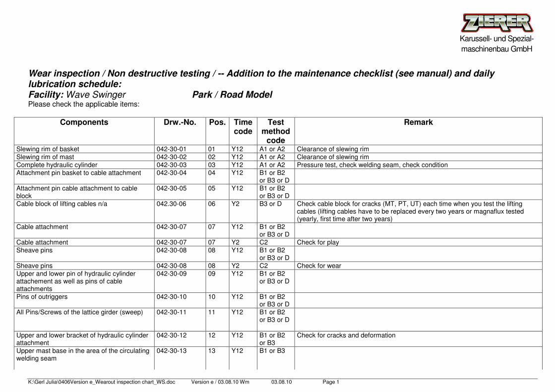
Wear inspection / Non destructive testing / -- Addition to the maintenance checklist (see manual) and daily lubrication schedule: Facility: Wave Swinger Park / Road Model Please check the applicable items:
Components Drw.-No. Pos. Time code
Test method
code
Remark
Slewing rim of basket 042-30-01 01 Y12 A1 or A2 Clearance of slewing rim Slewing rim of mast 042-30-02 02 Y12 A1 or A2 Clearance of slewing rim Complete hydraulic cylinder 042-30-03 03 Y12 A1 or A2 Pressure test, check welding seam, check condition Attachment pin basket to cable attachment 042-30-04 04 Y12 B1 or B2
or B3 or D
Attachment pin cable attachment to cable block
042-30-05 05 Y12 B1 or B2 or B3 or D
Cable block of lifting cables n/a 042.30-06 06 Y2 B3 or D Check cable block for cracks (MT, PT, UT) each time when you test the lifting cables (lifting cables have to be replaced every two years or magnaflux tested (yearly, first time after two years)
Cable attachment 042-30-07 07 Y12 B1 or B2 or B3 or D
Cable attachment 042-30-07 07 Y2 C2 Check for play Sheave pins 042-30-08 08 Y12 B1 or B2
or B3 or D
Sheave pins 042-30-08 08 Y2 C2 Check for wear Upper and lower pin of hydraulic cylinder attachement as well as pins of cable attachments
042-30-09 09 Y12 B1 or B2 or B3 or D
Pins of outriggers 042-30-10 10 Y12 B1 or B2 or B3 or D
All Pins/Screws of the lattice girder (sweep)
042-30-11 11 Y12 B1 or B2 or B3 or D
Upper and lower bracket of hydraulic cylinder attachment
042-30-12 12 Y12 B1 or B2 or B3
Check for cracks and deformation
Upper mast base in the area of the circulating welding seam
042-30-13 13 Y12 B1 or B3
K:\Gerl Julia\0406Version e_Wearout inspection chart_WS.doc Version e / 03.08.10 Wm 03.08.10 Page 2
Karussell- und Spezial- maschinenbau GmbH
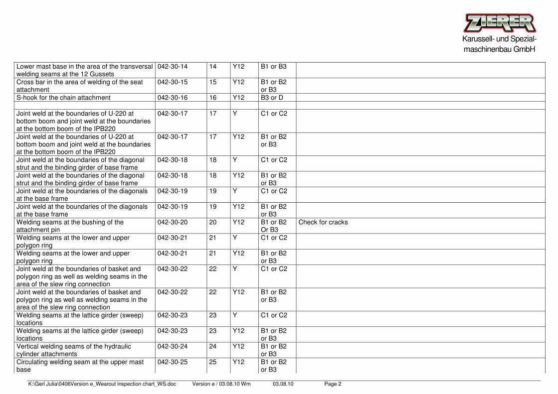
Lower mast base in the area of the transversal welding seams at the 12 Gussets
042-30-14 14 Y12 B1 or B3
Cross bar in the area of welding of the seat attachment
042-30-15 15 Y12 B1 or B2 or B3
S-hook for the chain attachment 042-30-16 16 Y12 B3 or D Joint weld at the boundaries of U-220 at bottom boom and joint weld at the boundaries at the bottom boom of the IPB220
042-30-17 17 Y C1 or C2
Joint weld at the boundaries of U-220 at bottom boom and joint weld at the boundaries at the bottom boom of the IPB220
042-30-17 17 Y12 B1 or B2 or B3
Joint weld at the boundaries of the diagonal strut and the binding girder of base frame
042-30-18 18 Y C1 or C2
Joint weld at the boundaries of the diagonal strut and the binding girder of base frame
042-30-18 18 Y12 B1 or B2 or B3
Joint weld at the boundaries of the diagonals at the base frame
042-30-19 19 Y C1 or C2
Joint weld at the boundaries of the diagonals at the base frame
042-30-19 19 Y12 B1 or B2 or B3
Welding seams at the bushing of the attachment pin
042-30-20 20 Y12 B1 or B2 Or B3
Check for cracks
Welding seams at the lower and upper polygon ring
042-30-21 21 Y C1 or C2
Welding seams at the lower and upper polygon ring
042-30-21 21 Y12 B1 or B2 or B3
Joint weld at the boundaries of basket and polygon ring as well as welding seams in the area of the slew ring connection
042-30-22 22 Y C1 or C2
Joint weld at the boundaries of basket and polygon ring as well as welding seams in the area of the slew ring connection
042-30-22 22 Y12 B1 or B2 or B3
Welding seams at the lattice girder (sweep) locations
042-30-23 23 Y C1 or C2
Welding seams at the lattice girder (sweep) locations
042-30-23 23 Y12 B1 or B2 or B3
Vertical welding seams of the hydraulic cylinder attachments
042-30-24 24 Y12 B1 or B2 or B3
Circulating welding seam at the upper mast base
042-30-25 25 Y12 B1 or B2 or B3
K:\Gerl Julia\0406Version e_Wearout inspection chart_WS.doc Version e / 03.08.10 Wm 03.08.10 Page 3
Karussell- und Spezial- maschinenbau GmbH
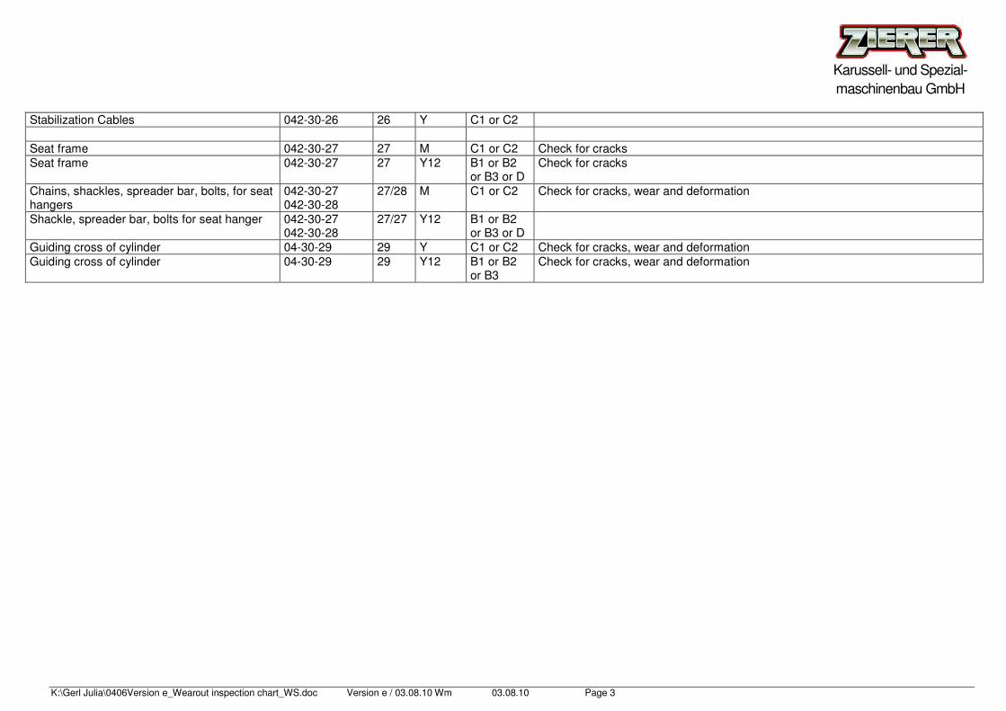
Stabilization Cables 042-30-26 26 Y C1 or C2 Seat frame 042-30-27 27 M C1 or C2 Check for cracks Seat frame 042-30-27 27 Y12 B1 or B2
or B3 or D Check for cracks
Chains, shackles, spreader bar, bolts, for seat hangers
042-30-27 042-30-28
27/28 M C1 or C2 Check for cracks, wear and deformation
Shackle, spreader bar, bolts for seat hanger 042-30-27 042-30-28
27/27 Y12 B1 or B2 or B3 or D
Guiding cross of cylinder 04-30-29 29 Y C1 or C2 Check for cracks, wear and deformation Guiding cross of cylinder 04-30-29 29 Y12 B1 or B2
or B3 Check for cracks, wear and deformation
K:\Gerl Julia\0406Version e_Wearout inspection chart_WS.doc Version e / 03.08.10 Wm 03.08.10 Page 4
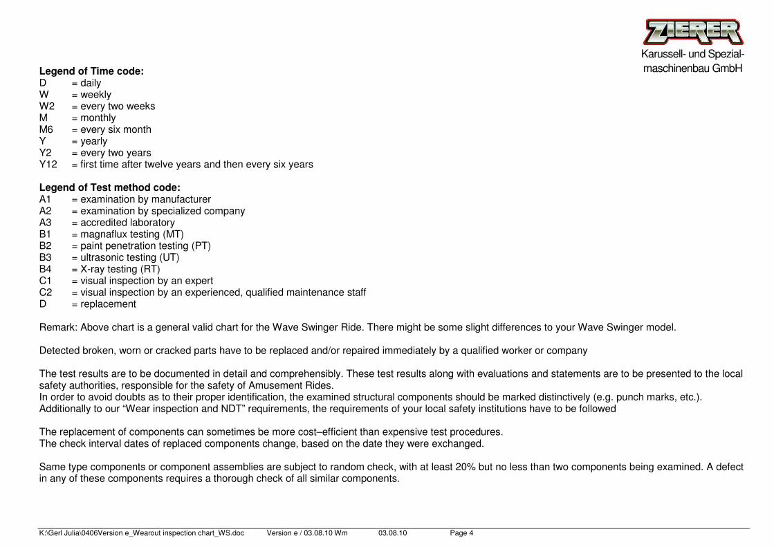
Karussell- und Spezial- maschinenbau GmbH Legend of Time code:
D = daily W = weekly W2 = every two weeks M = monthly M6 = every six month Y = yearly Y2 = every two years Y12 = first time after twelve years and then every six years Legend of Test method code: A1 = examination by manufacturer A2 = examination by specialized company A3 = accredited laboratory B1 = magnaflux testing (MT) B2 = paint penetration testing (PT) B3 = ultrasonic testing (UT) B4 = X-ray testing (RT) C1 = visual inspection by an expert C2 = visual inspection by an experienced, qualified maintenance staff D = replacement Remark: Above chart is a general valid chart for the Wave Swinger Ride. There might be some slight differences to your Wave Swinger model. Detected broken, worn or cracked parts have to be replaced and/or repaired immediately by a qualified worker or company The test results are to be documented in detail and comprehensibly. These test results along with evaluations and statements are to be presented to the local safety authorities, responsible for the safety of Amusement Rides. In order to avoid doubts as to their proper identification, the examined structural components should be marked distinctively (e.g. punch marks, etc.). Additionally to our “Wear inspection and NDT” requirements, the requirements of your local safety institutions have to be followed The replacement of components can sometimes be more cost–efficient than expensive test procedures. The check interval dates of replaced components change, based on the date they were exchanged. Same type components or component assemblies are subject to random check, with at least 20% but no less than two components being examined. A defect in any of these components requires a thorough check of all similar components.
(for completeness pls. See hereunder an extract from the service manual )
Maintenance Checklist
To increase safety and extend the life of each component as well as the reliability of the whole construction the persons responsible for maintenance and attendance of the ride must be instructed to regularly and carefully inspect and maintain the entire ride according to the following check list.
For any problems you cannot solve contact the address below. Before contacting make sure all errors which caused the breakdown are written down. Did you notice any irregularities prior to this breakdown? Who is the person to contact? Under which phone number can he be reached. An address to which spare parts may be shipped if required would be very helpful as well.
Contact address:
Zierer Karussell- und Spezialmaschinenbau GmbH Moosgasse 4 94560 Neuhausen / Offenberg Phone.: +49 991/9106-0 Germany Fax: +49 991/9106 84
K:\Gerl Julia\0406Version e_Wearout inspection chart_WS.doc Version e / 03.08.10 Wm 03.08.10 Page 6
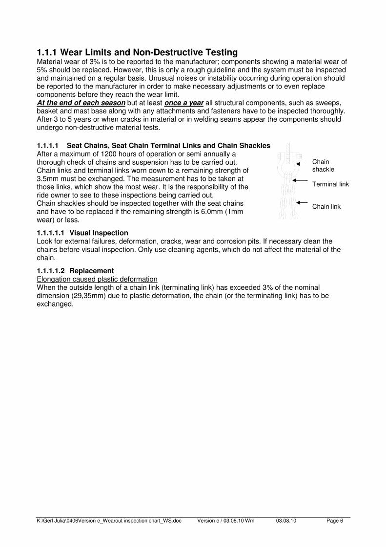
1.1.1 Wear Limits and Non-Destructive Testing Material wear of 3% is to be reported to the manufacturer; components showing a material wear of 5% should be replaced. However, this is only a rough guideline and the system must be inspected and maintained on a regular basis. Unusual noises or instability occurring during operation should be reported to the manufacturer in order to make necessary adjustments or to even replace components before they reach the wear limit. At the end of each season but at least once a year all structural components, such as sweeps, basket and mast base along with any attachments and fasteners have to be inspected thoroughly. After 3 to 5 years or when cracks in material or in welding seams appear the components should undergo non-destructive material tests. 1.1.1.1 Seat Chains, Seat Chain Terminal Links and Chain Shackles After a maximum of 1200 hours of operation or semi annually a thorough check of chains and suspension has to be carried out. Chain links and terminal links worn down to a remaining strength of 3.5mm must be exchanged. The measurement has to be taken at those links, which show the most wear. It is the responsibility of the ride owner to see to these inspections being carried out. Chain shackles should be inspected together with the seat chains and have to be replaced if the remaining strength is 6.0mm (1mm wear) or less.
1.1.1.1.1 Visual Inspection Look for external failures, deformation, cracks, wear and corrosion pits. If necessary clean the chains before visual inspection. Only use cleaning agents, which do not affect the material of the chain.
1.1.1.1.2 Replacement Elongation caused plastic deformation When the outside length of a chain link (terminating link) has exceeded 3% of the nominal dimension (29,35mm) due to plastic deformation, the chain (or the terminating link) has to be exchanged.
Chain shackle Terminal link Chain link
K:\Gerl Julia\0406Version e_Wearout inspection chart_WS.doc Version e / 03.08.10 Wm 03.08.10 Page 7
ESSENTIAL INFORMATION FOR THE USE OF CHAINS MADE OF STAINLESS STEEL Improper treatment of stainless steel chains will lead to loss of rust protection!! If the protective layer on the chain surface is damaged the chain is no longer protected against corrosion. Please follow the instructions below to avoid loss of rust protection:
• Do not drag the chains along steel or metal parts during installation.
• Do not do any grinding (using an angle grinder for instance) or welding jobs near the chains. Sparks too will damage the chain surface.
• Do not use tools, which are normally used for working on untreated steel (for example wire brushes, grinding wheels...)
• Always remove industrial dust by cleaning the chains regularly.
• Tempering colors as caused by welding for instance, will also result in corrosion if the stains are not thoroughly removed from the chains.
NOTE: Any corrosive material touching stainless steel chains may cause deterioration of the
chains rust protection!
That means only correct treatment of the chains will guarantee rust-free chains. Improper handling and disregarding the above guidelines will probably lead to strong corrosion of stainless steel chains within only one year.
Neither Zierer nor the chain manufacturer will grant any warranty in case of improper treatment of stainless steel chains. Therefore please check every new stainless steel chain for any damages immediately when receiving it. Later complaints cannot be considered since inexpert treatment and handling of the chains must be assumed. The above guidelines for proper treatment also apply to all stainless steel parts that have been installed in attractions and ride manufactured by Zierer.
1.1.1.2 Shackles The shackles have to be checked when inspecting the seat chains. They have to be replaced when the wear measures 1,5mm - 2,0 mm.
1.1.1.3 S Hooks
1.1.1.3.1 Maintenance / Replacement of S-hooks
The S-hook is a special product manufactured and supplied only by ZIERER Karussell u. Fahrzeugbau GmbH. For safety reasons it is absolute necessary to follow the instructions of the manufacturer regarding maintenance and / or replacement. Subsequent treatment of the S-hooks by a third party is not permitted. Especially surface welding of the unit moulds (radius) leads to embrittlement of the material and can cause fractures. The S-hook has to be replaced if the wear measures more than 1.5 – 2.0 mm more on the unit moulds.
1.1.1.4 Spreader Bars Examine together with the chains. The spreader bar needs to be exchanged if the maximum allowed wear of 1,5 - 2,0mm at the boreholes for the shackles is reached. Also check the polyamide bushing in the center for cracks and to replace it if necessary. 1.1.1.5 Lifting Cables: In accordance with DIN 15 020, and TÜV Bayern both sets of lifting cables have to be magnaflux tested or have to be replaced at least every two years of operation In addition, these cables have to be checked daily over the entire length for wire breaks, corrosion, abrasion, structural abnormalities or deformation and may have to be replaced at even shorter intervals if necessary.
K:\Gerl Julia\0406Version e_Wearout inspection chart_WS.doc Version e / 03.08.10 Wm 03.08.10 Page 8
1.1.1.5.1 Wire Breaks Wire breaks initially occur after a certain running period and then continue to occur after increasingly shorter time periods.
a) a) The wire rope is to be replaced when the number of breaks and the wear increases to 10% and more within 0,5 meters anywhere along the cable.
b) The wire rope is to be discarded immediately when wire break clusters appear.
c) The wire rope is to be discarded immediately when a wire strand is fractured.
1.1.1.5.2 Corrosion Corrosion occurs particularly in corrosive environment, e.g. sea climate. Wire ropes stored outdoors for longer periods will also corrode. Corrosion of the outer wires can easily be noticed by visual inspection. Corrosion of wires not visible from the outside is difficult to detect. Both, the static breaking strength as well as the stability of the wire rope will be reduced by corrosion due to corrosion pits and reduction of the metallic cross section. The cable must be replaced when the cable diameter in any given spot has decreased by 10% compared to the nominal size, even though no wire breaks are visible.
1.1.1.5.3 Abrasion Wire abrasion occurs as "internal abrasion" due to the movements of strands and wires against each other by bending the wire rope and as "external abrasion" due to movement between wire rope and pulley. A dusty environment increases the abrasion. Both the static breaking strength as well as the stability of the wire rope becomes reduced by abrasion, due to fretting pits and reduction of the metallic cross section. The wire cable has to be replaced if anywhere along the cable the cable diameter is decreased by 10% compared to the nominal size, even though there are no visible wire breaks.
1.1.1.5.4 Structural Changes
Strain on the wire rope during operation causes structural changes, which will reduce the rope diameter.
The cable must be replaced when over a longer stretch the cable diameter has decreased by 15% compared to the nominal size, even though there are no visible wire breaks.
1.1.1.5.5 Deformation Deformations of the wire rope are visible changes in the rope structure. Deformation usually generates a destabilization of the rope structure, at least near the deformed area. When a wire rope is visibly deformed an exchange of the lift cable sets is recommended, as the destabilization of the rope structure also means increased abrasion. The consequential damage leads to an accelerated rate of wire breaks, which are crucial for the replacement state of wear.
Please proceed as follows to exchange the cables:
1) Bring the ride to its load/unload position.
2) For manual lowering use the setup unit (see function description of hydraulic system, 4.3.5), the carrousel is lowered until it comes to rest on the basket stops and the lift cables become slack.
3) Slide up securing pins. The pins attaching the cables to the basket may now be removed through the basket openings by using the special tool.
4) Remove the top dome, the cover plate on the side of the mast and the safety clip above the pulleys
5) The cross-brace inside the mast is now accessible. The cable attachment bolts may now be removed.
K:\Gerl Julia\0406Version e_Wearout inspection chart_WS.doc Version e / 03.08.10 Wm 03.08.10 Page 9
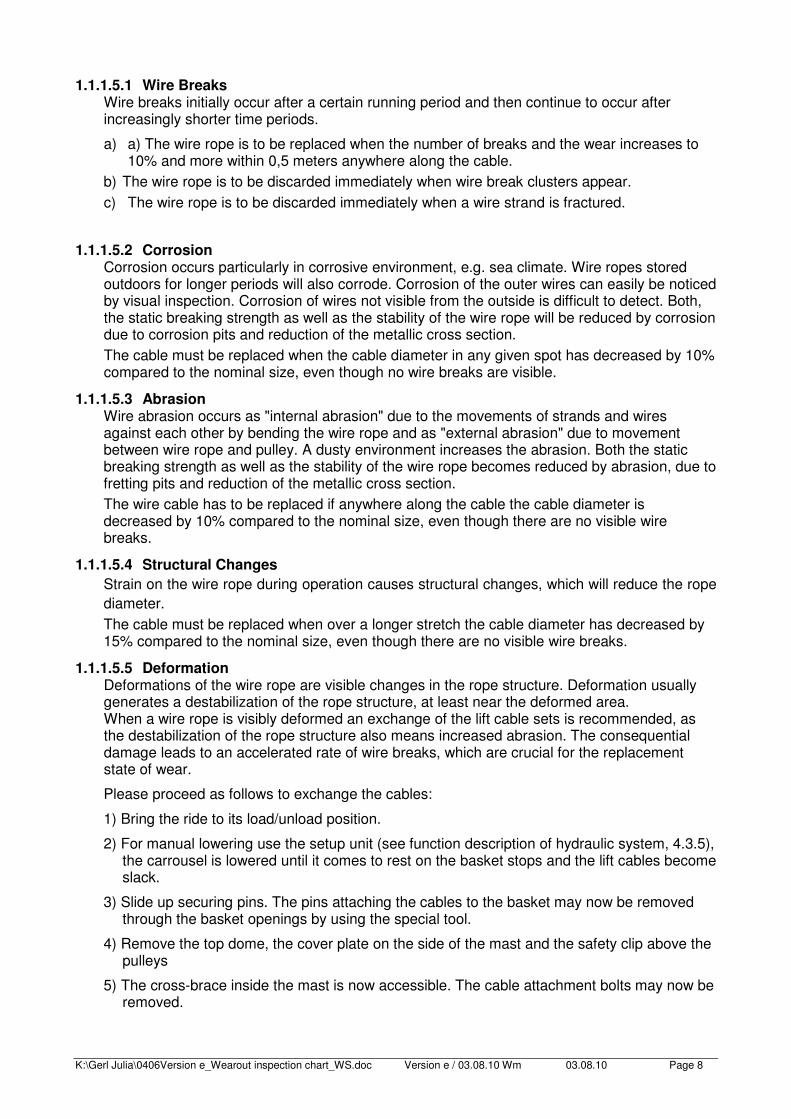
6) Now the pulleys can be removed. For easier lifting and disassembly an eyebolt can be inserted into the borehole on the pulleys. Pull out the center pins
Picture 24
Special care must be taken of the nylon washers between the pulleys and the walls.
7) Now the cables can be exchanged. When inserting the new cables make sure they are not twisted.
8) Installment is in reverse order to the sequence of disassembly. Make sure all safety plates and safety pins are put back in place.
1.1.1.6 Sheaves Every time the lifting cables are replaced, the rib treads of the sheaves have to be inspected with a radius gauge (r = 9,5mm), using the light gap method. When a rib tread deviates from the contour of the radius gauge the respective sheave must be replaced as well. Tolerances are not permissible, since these can again cause deformation of the new wire rope and lead to wire breaks at an accelerated rate.
1.2 Maintenance of Mechanical Parts Maintenance of mechanical parts is limited to closely checking for wear and tear and the examination of the primary connecting components with their safety backups as well as the thorough lubrication of the rotating parts and contacting parts (except the slip ring assembly.) To efficiently lubricate these parts raise the carrousel about 2m to make the points of lubrication accessible.
K:\Gerl Julia\0406Version e_Wearout inspection chart_WS.doc Version e / 03.08.10 Wm 03.08.10 Page 10
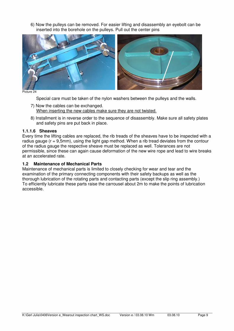
1.2.1 Slewing Ring in the Basket It is lubricated weekly at the 6 lubricating nipples (�) below the basket. The teeth of the ring gear are greased with a brush (∆) through the oval-shaped opening in the basket from above (Attention, Danger! Slip rings are live! Switch off power supply first!)
Picture 25
Picture 26
Grease nipple
Toothing
K:\Gerl Julia\0406Version e_Wearout inspection chart_WS.doc Version e / 03.08.10 Wm 03.08.10 Page 11
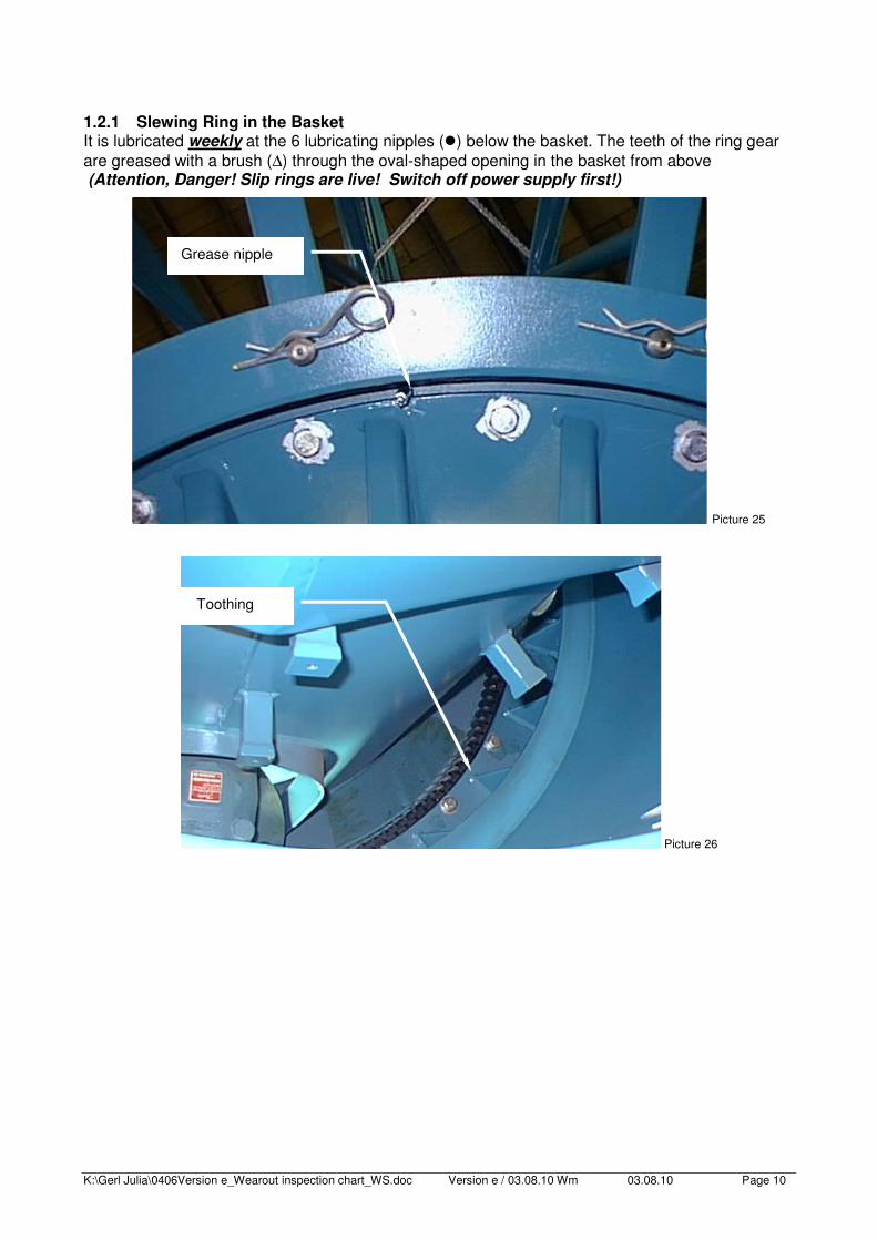
1.2.2 Guide Rollers
The guide rollers (4 rollers) running inside along the guide rail of the mast on the upper basket (2 pieces) and the lower basket (2 pieces) are to be greased daily through the lubricating nipples (�) extending to the outside of the inner basket.
The guide rollers (4 pieces) running outside along the guide rail of the mast are to be greased daily through lubricating nipples (�) positioned on one side of the guide rollers.
Picture27
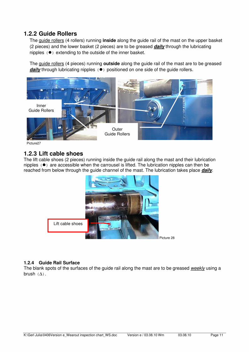
1.2.3 Lift cable shoes The lift cable shoes (2 pieces) running inside the guide rail along the mast and their lubrication nipples (�) are accessible when the carrousel is lifted. The lubrication nipples can then be reached from below through the guide channel of the mast. The lubrication takes place daily.
Picture 28
1.2.4 Guide Rail Surface The blank spots of the surfaces of the guide rail along the mast are to be greased weekly using a brush (∆).
Outer Guide Rollers
Inner Guide Rollers
Lift cable shoes
K:\Gerl Julia\0406Version e_Wearout inspection chart_WS.doc Version e / 03.08.10 Wm 03.08.10 Page 12
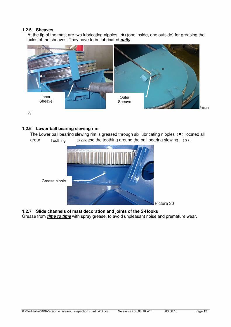
1.2.5 Sheaves
At the tip of the mast are two lubricating nipples (�)(one inside, one outside) for greasing the axles of the sheaves. They have to be lubricated daily.
Picture 29
1.2.6 Lower ball bearing slewing rim
The Lower ball bearing slewing rim is greased through six lubricating nipples (�) located all around. A brush is used to grease the toothing around the ball bearing slewing. (∆).
Picture 30
1.2.7 Slide channels of mast decoration and joints of the S-Hooks Grease from time to time with spray grease, to avoid unpleasant noise and premature wear.
Inner Sheave
Outer Sheave
Grease nipple
Toothing

K:\Gerl Julia\0406Version e_Wearout inspection chart_WS.doc Version e / 03.08.10 Wm 03.08.10 Page 13