Embed Size (px)
DESCRIPTION
Radiation Pressure Noise Experiment in Hannover. Kazuhiro Yamamoto Henning Kaufer, Tobias Westphal, Daniel Friedrich, Helge Mueller-Ebhardt, Stefan Gossler, Karsten Danzmann and Roman Schnabel Max-Planck-Institut fuer Gravitationsphysik (Albert-Einstein-Institut) - PowerPoint PPT Presentation
Citation preview
1
Kazuhiro Yamamoto
Henning Kaufer Tobias Westphal Daniel Friedrich Helge Mueller-Ebhardt
Stefan Gossler Karsten Danzmann and Roman SchnabelMax-Planck-Institut fuer Gravitationsphysik (Albert-Einstein-Institut)
Institut fuer Gravitationsphysik Leibniz Universitaet Hannover
Radiation Pressure NoiseExperiment in Hannover
Kentaro SomiyaWaseda University
Farid Y Khalili Stefan L DanilishinMoscow State University
19 May 2010 Gravitational-Wave Advanced Detector Workshop Hearton Hotel Kyoto Kyoto Japan
0AbstractRadiation pressure noise measurement
with extremely light
but translucent mechanical oscillator
New topology Michelson-Sagnac interferometer
Theoretical outlines
Current status of experiment
Future work
2
3
CLIO-MQM (Cryogenic Laser Interferometer Observatory-Macroscopic Quantum Measurement)
Workshop
24th and 25th May
Waseda Institute for Advanced Study Tokyo Japan
SL Danilishin ldquoTowards mechanical non-Gaussian
states with optical interferometersrdquo
FY Khalili ldquoUp-converter regime in the membrane
experimentsrdquo
K Yamamoto ldquoNano-gram membrane experiment
at AEIrdquo
Related talks
Contents
1 Introduction
2 Current status
3 Future work
4 Summary
4
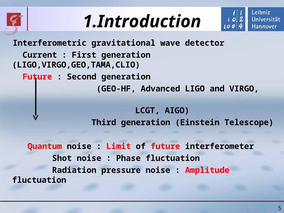
1Introduction Interferometric gravitational wave detector
Current First generation (LIGOVIRGOGEOTAMACLIO)
Future Second generation
(GEO-HF Advanced LIGO and VIRGO
LCGT AIGO)
Third generation (Einstein Telescope)
Quantum noise Limit of future interferometer
Shot noise Phase fluctuation
Radiation pressure noise Amplitude fluctuation
5
6
1 IntroductionRadiation pressure noise (1)
httpspacefilesblogspotcom
Photons come at random (amplitude fluctuation) Back action of photon is also at randomrarr Radiation pressure noise
7
shot noise
quantum radiation pressure noise
standard quantum limit
quantum noise with 100x increased laserpower
1 Introduction Standard Quantum Limit
Nobody observed radiation pressure noise
Large radiation pressure noise
High laser power Light mass
~ m12
~ P12
~ P-12
Standard Quantum Limit (SQL) is a fundamental limit for
naively optimized conventional interferometers
8
Mechanical properties
frame 752 mm2 x 200 micromArea 15 mm x 15 mmThickness 75 nm Effective mass ~ 100 ngResonant frequency ~ 73 kHz
Optical properties
Power Reflectance ~ 33 Absorption le 150 ppmFlatness 1 nmMicro roughness 02 nmScattering rarr 0
1 Introduction Membrane (Si3N4 in frame)
JD Thompson et al Nature 452 (2008) 72-76
1 IntroductionMichelson-Sagnac interferometer(1)
9
Membrane
From laser source
Beamsplitter
Steering mirror
Steering mirror
1 Introduction Michelson-Sagnac interferometer(2)
10
Sagnac mode
Michelson mode
Anti symmetric port (no light of Sagnac mode)
Symmetric port
Membrane position is adjusted to keep this port dark
11
1 Introduction Michelson-Sagnac interferometer(3)
Steering mirror
Steering mirror
Membrane
Beamsplitter
Laser source
Power recyclingmirror
Signal recycling mirror
Recycling techniques are useful even if the membrane reflectance is low
1 Introduction Goal sensitivity
12
Temperature 1 KQ 107
Effective Mass 125 ngResonance 75 kHzPower at BS 1 WSignal recycling mirror 998 amplitude reflectance
Radiation pressure noise is 2 and 3 times larger than shot noise and thermal noise
K Yamamoto et al Physical Review A 81 (2010) 033849
1 Introduction Node of Sagnac mode
Sagnac mode Clockwise and counterclockwise beams
There is interference between them
Standing wave
Nodes and anti nodes
Anti symmetric port is dark
Membrane must be on node or anti-node
We prefer membrane on node because of absorption
13
2 Current status Membrane (Si3N4 in frame)
14
Mechanical properties
frame 752 mm2 x 200 micromArea 15 mm x 15 mmThickness 75 nm Effective mass ~ 100 ngResonant frequency ~ 73 kHzQ ~ 13 x 106
Optical properties
Power reflectance ~ 33 Absorption le 150 ppmFlatness 1 nmMicro roughness 02 nmScattering rarr 0
JD Thompson et al Nature 452 (2008) 72-76
about1 mm
15
2 Current status Membrane (Si3N4 in frame)
Heat absorption in membrane (in Michelson-Sagnac interferometer)
Node of Sagnac mode (small absorption)
Anti node (large absorption)
Fitting Second polynomial(Physical mechanism is not clear yet)
First mode
16
2 Current status Membrane (Si3N4 in frame)
Heat absorption in membrane
Second mode
17
2 Current status Membrane (Si3N4 in frame)
Heat absorption in membrane
Fourth mode Temperature gradient
2 Current status Michelson-Sagnac interferometer
18
Without power and signal recycling
NdYAG laser EOM
Mode cleaner
Photodetector
Vacuum tank(10-6 mbar)
Photo detector(signal of membrane motion)
Membrane
2 Current status Inside vacuum tank
19
Membrane holder
Steering mirror
Steering mirror
Beam splitter
From lasersource
Antisymmeticport
20
2 Current status Measured power spectrum
On resonance Thermal noise
Off resonance Intensity noise
510-16 mrtHz
21
2 Current status Standard Quantum Limit on resonance
JILANIST group claims that their sensitivity is below Standard Quantum Limit (SQL)
JD Teufel et al Nature Nanotechnology 4 (2009) 820
4810-15 mrtHz
22
SQL
G Anetsberger et al Nature Physics 5 (2009) 909
Recent result from same group(arXiv10033752)
5710-16 mrtHz
2 Current status Standard Quantum Limit on resonance
Max-Planck-Institut (MPI) fuer Quantenoptik group also claims that their sensitivity is below Standard Quantum Limit (SQL)
23
Standard QuantumLimit (SQL) of NIST and MPI fuer Quantenoptik is constant around the resonance
Standard QuantumLimit (SQL) depends on (only) mechanical susceptibility
2 Current status Standard Quantum Limit on resonance
What is their definition of Standard Quantum Limit (SQL)
24
They compare off resonance sensitivity with Standard QuantumLimit (SQL) on resonance
Standard QuantumLimit (SQL) depends on (only) mechanical susceptibility
2 Current status Standard Quantum Limit on resonance
What is their difinition of Standard Quantum Limit (SQL)
25
Our sensitivity is also below Standard Quantum Limit (SQL) and better or comparable
510-16 mrtHz
2 Current status Standard Quantum Limit on resonance
3 Future work(1) Reduction of noise
(to observe off resonance thermal noise)
Laser intensity stabilization (in progress)
(2) Signal recycling
(3) Cryogenic apparatus (about 1K 3He evacuation)
Suspension
26
4 SummaryRadiation pressure noise measurement
with extremely light but translucent membrane
New topology Michelson-Sagnac interferometer
Goal sensitivity Nodes of Sagnac mode
Current status of experiment
Incident power dependence of resonant frequency
Operation without power and signal recycling
Current sensitivity (510-16 mrtHz)
Off resonance sensitivity
below Standard Quantum Limit (SQL) on resonance
Future work
Laser intensity stabilization
Cryogenic apparatus and so on 27
28
29
1 Introduction Radiation pressure noise
Vacuum
Frequency(Hz)
Sen
siti
vity
(r
tHz)
Radiation
pressure noise
Mirrorthermal noise
Advanced LIGO
30
1 Introduction Sizes of oscillators
TJ Kippenberg and K J Vahala Science 321 (2008) 1172
Resonant frequency
Effective Mass
Hz
MHz
kg
pg
31
Mechanical properties
frame 752 mm2 x 200 micromArea 15 mm x 15 mmThickness 75 nm Effective mass ~ 100 ngResonant frequency ~ 73 kHz
1 Introduction Membrane (Si3N4 in frame)
JD Thompson et al Nature 452 (2008) 72-76
32
GEO600 LIGO3 Adv LIGO3
Sakata1 Goszligler2 Corbitt3 Ours4
meff 1 kg 25 kg 10 kg 23 mg 05g 1 g 50 ng
P [kW] 10 10 830 12 0003 20 006
Pm [kWkg] 10 4 83 52103 6 20103 12109
Pm [kWkg] 3 13 29 48000 110 4500 5109
1 N Mavalvala Elba conference (2008)2 CM Mow-Lowry et al Journal of PhysicsCongerence Series 32 362-367 (2006)3 T Corbitt Elba conference (2008)4 JD Thompson et al Nature 452 72-76 (2008)
1 Introduction compare different approaches
2 Theoretical outlines
I will explain
Two differences from simple Michelson
(1)Radiation pressure noise on membrane
(2)Node of Sagnac mode
and goal sensitivity of our interferometer
33
2 Theoretical outlines Radiation pressure noise on membrane
34
Membrane
InterferenceInterference
Conclusion Radiation pressure noise is proportional to power reflectance of membraneeven if the membrane is at node of Sagnac mode
2 Current status Optical table
35
Laser source
Mode cleaner
Periscope
Vacuum tank
36
2 Current status Membrane holder
Stage
PZT with hole
Membrane frame
Membrane
3 Current status Michelson-Sagnac interferometer
37
Beam splitter
Membrane holder Steering
mirror
Steering mirror
From lasersource
2 Theoretical outlines Standart Quantum Limit (SQL)
SQL of Michelson-Sagnac interferometer (one membrane)
SQL of Fabry-Perot Michelson interferometer (four mirrors)
SQL of simple Michelson interferometer (two mirrors)
H Mechanical responce of one oscillatorOur conjucture SQL depends on number of mirrors (n)
38
39
3 Current status Calibration
Calibration (photo detector output vs displacement of membrane) is possible as like simple Michelson interferometer
Membrane displacement [nm]
Ph
oto
det
ecto
r o
utp
ut
po
wer
[a
u] Measured fringe
Fitting value
Measured results agree with fitting
Quater of wavelength
3 Current status Resonant frequencies of membrane
40
Fundamental mode (73kHz)
Frequency (kHz)
Am
pli
tud
e (d
B)
3 Current status Resonant frequencies of membrane
41
Difference between theory and measurement (~1)
Frequency [kHz]
Dif
fere
nce
bet
wee
n t
heo
ry
and
mea
sure
men
t [k
Hz]
75 nm
15 mm
42
bull Thermoelastic dampingrarr Estimation Q ~ 5 x 10⁷
bull Residual gas damping rarr Vacuum (~ 10-6 mbar)
3 Current status Q-values of membrane
bull Recoil loss rarr Estimation Q gt 107
bull Bulk loss rarr Unknownbull Loss on surface rarr Unknown
bull Our measurement Q ~ 13 x106 300 K
bull Measurement of other group Q ~ 1 x10⁷ 03 K BM Zwickl et al Applied Physics Letters 92(2008)103125
Time [sec]
Pressure [mbar]Q
MeasurementTheory
10-6
200 microm
75 nm
3 Current status Reflectance of membrane
Membrane
as etalon
Po
wer
ref
lect
ivit
y
43
Incident angle [degree]
P-polarized
S-polarized
44
vacuum systemto reach lt 10-6 mbar
actual pressurein experiment1510-7 mbar
backing pump pressure10-1 mbar not good enoughto use ducted vacuum
45
Q-measurementactual status of the table
laser preparation
membrane
periscopes
46
bull many unknown valuesbull had no verification for Harris results
rarr designed very sturdy mount
recent results
it should be sufficient to conserve Q of the small frame to be not limited
we will design a smaller mount for further experiment
recoil lossenergy transfer to membraneholder limits Q
osc
sup
sup
osc1-sup
1-osc
1osc QQQ
recoil
m
m
47
Q-measurementactual readout scheme
bull 106 periods per ringdowntime
rarr use lock in amplifier (variable filters)
our lock-in amp is too slow
rarr mixer shifts signal to some kHz
0f periodper energyloss
energy contained totalQ
ringdown time
48
Q-measurementactual readout scheme
106 periods per ringdowntime
rarr mix signal down (shift to lower freq)
Lock-in amp is too slow
rarr second mixer for some kHz
49
nonlinearity of the oscillationcomparison of our results to Harris`
Harris et al APL 92 (2008)our results
50
locking scheme for PR-cavityusing Pound Drever Hall signal
bull michelson acts as mirror
bull membrane-position dependent reflectivity (and phase)
51
locking scheme for Michelson interferometerusing Schnupp asymmetry
bull need different armlength
bull IFO reflecting carrierbull IFO partly transmitting sidebands
bull errorsignal in transmission
problems
bull need to preserve contrast
bull small asymmety
bull high modulation frequency
52
outlookfurther techniques
bull dual recycling
bull frequency stabilisation
with reference cavity
bull suspended interferometer
to isolate from seismic motion
(like Tokyo- group)
53
KryostatReduzierung thermischen Rauschens
Mehrstufiges Konzept (Zwiebelschalenmodell)
rarr Interferometer durch 4He gekuumlhlt
rarr Membran daruumlber hinaus durch 3He gekuumlhlt
Kryostat verursacht bdquoErschuumltterungenldquo
rarr Seismische Entkopplung des Interferometers
Thermisches Rauschen erfordert Kuumlhlung
54
Erwartete Empfindlichkeitfuumlr kryogene Temperaturen
rarr Schrotrauschen Faktor 2rarr therm Rauschen Faktor 3
Temperatur 1 KGuumlte 107
Effektive Masse 125 ngLeistung 400 WResonanz 50 kHz(optische Feder)
Weitere Option bull Signal Recycling (nur gegen Schrotrauschen)
62
Groszlige Uumlberschriftkleine Uumlberschrift
Text
63
2 Theoretical outlines
Three differences from simple Michelson
(1)Radiation pressure noise on membrane
(2)Node of Sagnac mode
(3)Optical spring
63
2 Theoretical outlines Optical spring (1)
Optical spring (without cavity) Light acts as spring
Radiation pressure on membrane depends on its position
Radiation pressure changes
resonant frequency of membrane
6464
InterferenceInterference
Membrane
Shift
2 Theoretical outlines Optical spring (2)
Phase of Michelson mode Shift
Sign of shift on right side is opposite to that on left side
Phase of Sagnac mode No shift
6565
Left side of membrane
Sagnac
Michelson
Right side of membrane
Shift by membrane
Shift by membrane
Michelson
Sagnac
2 Theoretical outlines Optical spring (3)
Interference Constructive (larger power) on right side
Destructive (smaller power) on left side
Radiation pressure on right side becomes larger
(Optical spring effect)
6666
Sagnac
Michelson
Shift by membrane
Shift by membrane
Michelson
Sagnac
Left side of membrane Right side of membrane
2 Theoretical outlines Goal sensitivity
6767
Temperature 1 KQ 107
Effective Mass 125 ngPower at BS 400 WResonance 75 kHz(with optical spring)Resonance 50 kHz(without optical spring)
Shot noise Factor 2Thermal noise Factor 3
Option Signal Recycling 99 power reflectance Power at BS about 1W P
ow
er s
pec
tru
m d
ensi
ty [
mr
tHz]
Frequency[kHz]
Shot noiseQuantum noiseThermal noise
Without signal recycling
0AbstractRadiation pressure noise measurement
with extremely light
but translucent mechanical oscillator
New topology Michelson-Sagnac interferometer
Theoretical outlines
Current status of experiment
Future work
2
3
CLIO-MQM (Cryogenic Laser Interferometer Observatory-Macroscopic Quantum Measurement)
Workshop
24th and 25th May
Waseda Institute for Advanced Study Tokyo Japan
SL Danilishin ldquoTowards mechanical non-Gaussian
states with optical interferometersrdquo
FY Khalili ldquoUp-converter regime in the membrane
experimentsrdquo
K Yamamoto ldquoNano-gram membrane experiment
at AEIrdquo
Related talks
Contents
1 Introduction
2 Current status
3 Future work
4 Summary
4
1Introduction Interferometric gravitational wave detector
Current First generation (LIGOVIRGOGEOTAMACLIO)
Future Second generation
(GEO-HF Advanced LIGO and VIRGO
LCGT AIGO)
Third generation (Einstein Telescope)
Quantum noise Limit of future interferometer
Shot noise Phase fluctuation
Radiation pressure noise Amplitude fluctuation
5
6
1 IntroductionRadiation pressure noise (1)
httpspacefilesblogspotcom
Photons come at random (amplitude fluctuation) Back action of photon is also at randomrarr Radiation pressure noise
7
shot noise
quantum radiation pressure noise
standard quantum limit
quantum noise with 100x increased laserpower
1 Introduction Standard Quantum Limit
Nobody observed radiation pressure noise
Large radiation pressure noise
High laser power Light mass
~ m12
~ P12
~ P-12
Standard Quantum Limit (SQL) is a fundamental limit for
naively optimized conventional interferometers
8
Mechanical properties
frame 752 mm2 x 200 micromArea 15 mm x 15 mmThickness 75 nm Effective mass ~ 100 ngResonant frequency ~ 73 kHz
Optical properties
Power Reflectance ~ 33 Absorption le 150 ppmFlatness 1 nmMicro roughness 02 nmScattering rarr 0
1 Introduction Membrane (Si3N4 in frame)
JD Thompson et al Nature 452 (2008) 72-76
1 IntroductionMichelson-Sagnac interferometer(1)
9
Membrane
From laser source
Beamsplitter
Steering mirror
Steering mirror
1 Introduction Michelson-Sagnac interferometer(2)
10
Sagnac mode
Michelson mode
Anti symmetric port (no light of Sagnac mode)
Symmetric port
Membrane position is adjusted to keep this port dark
11
1 Introduction Michelson-Sagnac interferometer(3)
Steering mirror
Steering mirror
Membrane
Beamsplitter
Laser source
Power recyclingmirror
Signal recycling mirror
Recycling techniques are useful even if the membrane reflectance is low
1 Introduction Goal sensitivity
12
Temperature 1 KQ 107
Effective Mass 125 ngResonance 75 kHzPower at BS 1 WSignal recycling mirror 998 amplitude reflectance
Radiation pressure noise is 2 and 3 times larger than shot noise and thermal noise
K Yamamoto et al Physical Review A 81 (2010) 033849
1 Introduction Node of Sagnac mode
Sagnac mode Clockwise and counterclockwise beams
There is interference between them
Standing wave
Nodes and anti nodes
Anti symmetric port is dark
Membrane must be on node or anti-node
We prefer membrane on node because of absorption
13
2 Current status Membrane (Si3N4 in frame)
14
Mechanical properties
frame 752 mm2 x 200 micromArea 15 mm x 15 mmThickness 75 nm Effective mass ~ 100 ngResonant frequency ~ 73 kHzQ ~ 13 x 106
Optical properties
Power reflectance ~ 33 Absorption le 150 ppmFlatness 1 nmMicro roughness 02 nmScattering rarr 0
JD Thompson et al Nature 452 (2008) 72-76
about1 mm
15
2 Current status Membrane (Si3N4 in frame)
Heat absorption in membrane (in Michelson-Sagnac interferometer)
Node of Sagnac mode (small absorption)
Anti node (large absorption)
Fitting Second polynomial(Physical mechanism is not clear yet)
First mode
16
2 Current status Membrane (Si3N4 in frame)
Heat absorption in membrane
Second mode
17
2 Current status Membrane (Si3N4 in frame)
Heat absorption in membrane
Fourth mode Temperature gradient
2 Current status Michelson-Sagnac interferometer
18
Without power and signal recycling
NdYAG laser EOM
Mode cleaner
Photodetector
Vacuum tank(10-6 mbar)
Photo detector(signal of membrane motion)
Membrane
2 Current status Inside vacuum tank
19
Membrane holder
Steering mirror
Steering mirror
Beam splitter
From lasersource
Antisymmeticport
20
2 Current status Measured power spectrum
On resonance Thermal noise
Off resonance Intensity noise
510-16 mrtHz
21
2 Current status Standard Quantum Limit on resonance
JILANIST group claims that their sensitivity is below Standard Quantum Limit (SQL)
JD Teufel et al Nature Nanotechnology 4 (2009) 820
4810-15 mrtHz
22
SQL
G Anetsberger et al Nature Physics 5 (2009) 909
Recent result from same group(arXiv10033752)
5710-16 mrtHz
2 Current status Standard Quantum Limit on resonance
Max-Planck-Institut (MPI) fuer Quantenoptik group also claims that their sensitivity is below Standard Quantum Limit (SQL)
23
Standard QuantumLimit (SQL) of NIST and MPI fuer Quantenoptik is constant around the resonance
Standard QuantumLimit (SQL) depends on (only) mechanical susceptibility
2 Current status Standard Quantum Limit on resonance
What is their definition of Standard Quantum Limit (SQL)
24
They compare off resonance sensitivity with Standard QuantumLimit (SQL) on resonance
Standard QuantumLimit (SQL) depends on (only) mechanical susceptibility
2 Current status Standard Quantum Limit on resonance
What is their difinition of Standard Quantum Limit (SQL)
25
Our sensitivity is also below Standard Quantum Limit (SQL) and better or comparable
510-16 mrtHz
2 Current status Standard Quantum Limit on resonance
3 Future work(1) Reduction of noise
(to observe off resonance thermal noise)
Laser intensity stabilization (in progress)
(2) Signal recycling
(3) Cryogenic apparatus (about 1K 3He evacuation)
Suspension
26
4 SummaryRadiation pressure noise measurement
with extremely light but translucent membrane
New topology Michelson-Sagnac interferometer
Goal sensitivity Nodes of Sagnac mode
Current status of experiment
Incident power dependence of resonant frequency
Operation without power and signal recycling
Current sensitivity (510-16 mrtHz)
Off resonance sensitivity
below Standard Quantum Limit (SQL) on resonance
Future work
Laser intensity stabilization
Cryogenic apparatus and so on 27
28
29
1 Introduction Radiation pressure noise
Vacuum
Frequency(Hz)
Sen
siti
vity
(r
tHz)
Radiation
pressure noise
Mirrorthermal noise
Advanced LIGO
30
1 Introduction Sizes of oscillators
TJ Kippenberg and K J Vahala Science 321 (2008) 1172
Resonant frequency
Effective Mass
Hz
MHz
kg
pg
31
Mechanical properties
frame 752 mm2 x 200 micromArea 15 mm x 15 mmThickness 75 nm Effective mass ~ 100 ngResonant frequency ~ 73 kHz
1 Introduction Membrane (Si3N4 in frame)
JD Thompson et al Nature 452 (2008) 72-76
32
GEO600 LIGO3 Adv LIGO3
Sakata1 Goszligler2 Corbitt3 Ours4
meff 1 kg 25 kg 10 kg 23 mg 05g 1 g 50 ng
P [kW] 10 10 830 12 0003 20 006
Pm [kWkg] 10 4 83 52103 6 20103 12109
Pm [kWkg] 3 13 29 48000 110 4500 5109
1 N Mavalvala Elba conference (2008)2 CM Mow-Lowry et al Journal of PhysicsCongerence Series 32 362-367 (2006)3 T Corbitt Elba conference (2008)4 JD Thompson et al Nature 452 72-76 (2008)
1 Introduction compare different approaches
2 Theoretical outlines
I will explain
Two differences from simple Michelson
(1)Radiation pressure noise on membrane
(2)Node of Sagnac mode
and goal sensitivity of our interferometer
33
2 Theoretical outlines Radiation pressure noise on membrane
34
Membrane
InterferenceInterference
Conclusion Radiation pressure noise is proportional to power reflectance of membraneeven if the membrane is at node of Sagnac mode
2 Current status Optical table
35
Laser source
Mode cleaner
Periscope
Vacuum tank
36
2 Current status Membrane holder
Stage
PZT with hole
Membrane frame
Membrane
3 Current status Michelson-Sagnac interferometer
37
Beam splitter
Membrane holder Steering
mirror
Steering mirror
From lasersource
2 Theoretical outlines Standart Quantum Limit (SQL)
SQL of Michelson-Sagnac interferometer (one membrane)
SQL of Fabry-Perot Michelson interferometer (four mirrors)
SQL of simple Michelson interferometer (two mirrors)
H Mechanical responce of one oscillatorOur conjucture SQL depends on number of mirrors (n)
38
39
3 Current status Calibration
Calibration (photo detector output vs displacement of membrane) is possible as like simple Michelson interferometer
Membrane displacement [nm]
Ph
oto
det
ecto
r o
utp
ut
po
wer
[a
u] Measured fringe
Fitting value
Measured results agree with fitting
Quater of wavelength
3 Current status Resonant frequencies of membrane
40
Fundamental mode (73kHz)
Frequency (kHz)
Am
pli
tud
e (d
B)
3 Current status Resonant frequencies of membrane
41
Difference between theory and measurement (~1)
Frequency [kHz]
Dif
fere
nce
bet
wee
n t
heo
ry
and
mea
sure
men
t [k
Hz]
75 nm
15 mm
42
bull Thermoelastic dampingrarr Estimation Q ~ 5 x 10⁷
bull Residual gas damping rarr Vacuum (~ 10-6 mbar)
3 Current status Q-values of membrane
bull Recoil loss rarr Estimation Q gt 107
bull Bulk loss rarr Unknownbull Loss on surface rarr Unknown
bull Our measurement Q ~ 13 x106 300 K
bull Measurement of other group Q ~ 1 x10⁷ 03 K BM Zwickl et al Applied Physics Letters 92(2008)103125
Time [sec]
Pressure [mbar]Q
MeasurementTheory
10-6
200 microm
75 nm
3 Current status Reflectance of membrane
Membrane
as etalon
Po
wer
ref
lect
ivit
y
43
Incident angle [degree]
P-polarized
S-polarized
44
vacuum systemto reach lt 10-6 mbar
actual pressurein experiment1510-7 mbar
backing pump pressure10-1 mbar not good enoughto use ducted vacuum
45
Q-measurementactual status of the table
laser preparation
membrane
periscopes
46
bull many unknown valuesbull had no verification for Harris results
rarr designed very sturdy mount
recent results
it should be sufficient to conserve Q of the small frame to be not limited
we will design a smaller mount for further experiment
recoil lossenergy transfer to membraneholder limits Q
osc
sup
sup
osc1-sup
1-osc
1osc QQQ
recoil
m
m
47
Q-measurementactual readout scheme
bull 106 periods per ringdowntime
rarr use lock in amplifier (variable filters)
our lock-in amp is too slow
rarr mixer shifts signal to some kHz
0f periodper energyloss
energy contained totalQ
ringdown time
48
Q-measurementactual readout scheme
106 periods per ringdowntime
rarr mix signal down (shift to lower freq)
Lock-in amp is too slow
rarr second mixer for some kHz
49
nonlinearity of the oscillationcomparison of our results to Harris`
Harris et al APL 92 (2008)our results
50
locking scheme for PR-cavityusing Pound Drever Hall signal
bull michelson acts as mirror
bull membrane-position dependent reflectivity (and phase)
51
locking scheme for Michelson interferometerusing Schnupp asymmetry
bull need different armlength
bull IFO reflecting carrierbull IFO partly transmitting sidebands
bull errorsignal in transmission
problems
bull need to preserve contrast
bull small asymmety
bull high modulation frequency
52
outlookfurther techniques
bull dual recycling
bull frequency stabilisation
with reference cavity
bull suspended interferometer
to isolate from seismic motion
(like Tokyo- group)
53
KryostatReduzierung thermischen Rauschens
Mehrstufiges Konzept (Zwiebelschalenmodell)
rarr Interferometer durch 4He gekuumlhlt
rarr Membran daruumlber hinaus durch 3He gekuumlhlt
Kryostat verursacht bdquoErschuumltterungenldquo
rarr Seismische Entkopplung des Interferometers
Thermisches Rauschen erfordert Kuumlhlung
54
Erwartete Empfindlichkeitfuumlr kryogene Temperaturen
rarr Schrotrauschen Faktor 2rarr therm Rauschen Faktor 3
Temperatur 1 KGuumlte 107
Effektive Masse 125 ngLeistung 400 WResonanz 50 kHz(optische Feder)
Weitere Option bull Signal Recycling (nur gegen Schrotrauschen)
62
Groszlige Uumlberschriftkleine Uumlberschrift
Text
63
2 Theoretical outlines
Three differences from simple Michelson
(1)Radiation pressure noise on membrane
(2)Node of Sagnac mode
(3)Optical spring
63
2 Theoretical outlines Optical spring (1)
Optical spring (without cavity) Light acts as spring
Radiation pressure on membrane depends on its position
Radiation pressure changes
resonant frequency of membrane
6464
InterferenceInterference
Membrane
Shift
2 Theoretical outlines Optical spring (2)
Phase of Michelson mode Shift
Sign of shift on right side is opposite to that on left side
Phase of Sagnac mode No shift
6565
Left side of membrane
Sagnac
Michelson
Right side of membrane
Shift by membrane
Shift by membrane
Michelson
Sagnac
2 Theoretical outlines Optical spring (3)
Interference Constructive (larger power) on right side
Destructive (smaller power) on left side
Radiation pressure on right side becomes larger
(Optical spring effect)
6666
Sagnac
Michelson
Shift by membrane
Shift by membrane
Michelson
Sagnac
Left side of membrane Right side of membrane
2 Theoretical outlines Goal sensitivity
6767
Temperature 1 KQ 107
Effective Mass 125 ngPower at BS 400 WResonance 75 kHz(with optical spring)Resonance 50 kHz(without optical spring)
Shot noise Factor 2Thermal noise Factor 3
Option Signal Recycling 99 power reflectance Power at BS about 1W P
ow
er s
pec
tru
m d
ensi
ty [
mr
tHz]
Frequency[kHz]
Shot noiseQuantum noiseThermal noise
Without signal recycling
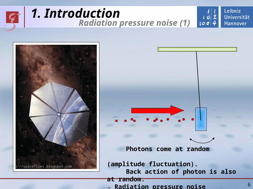
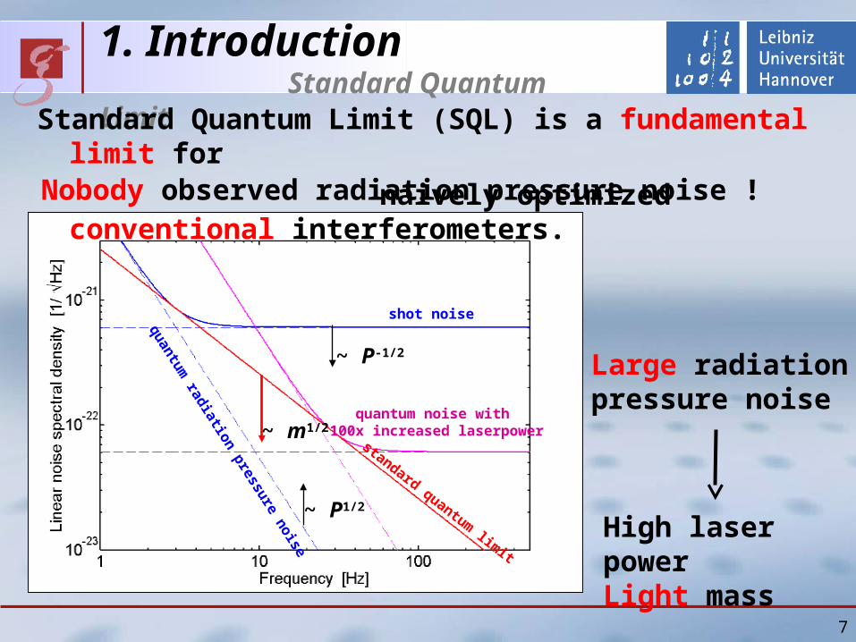
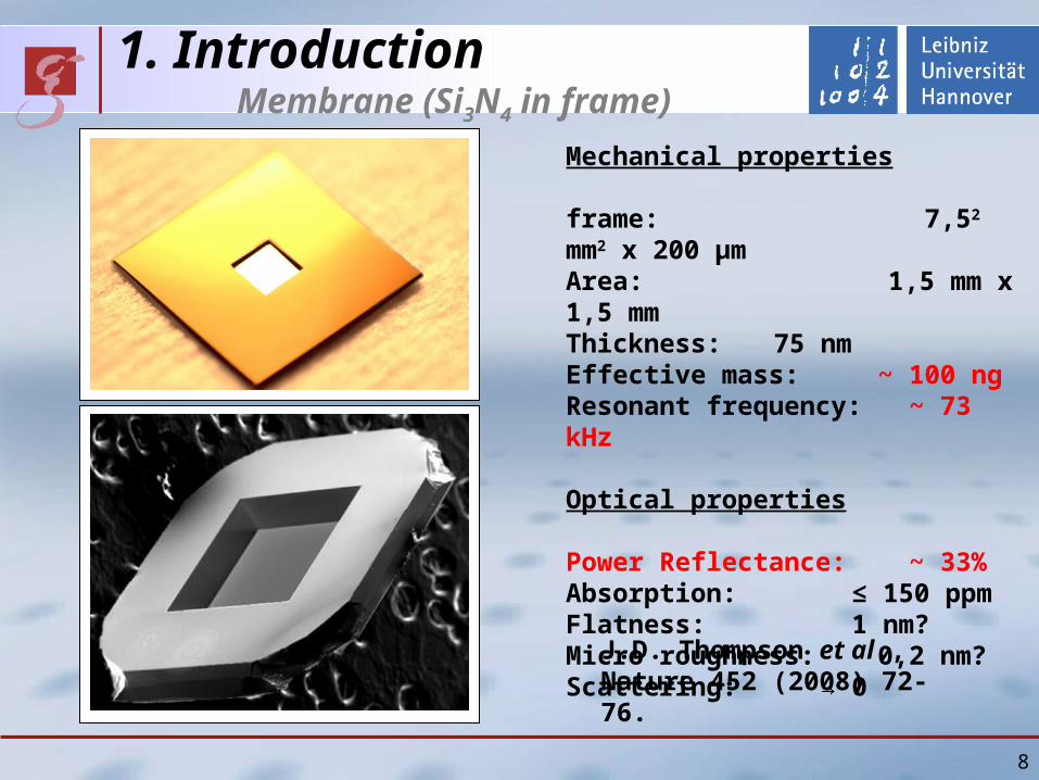
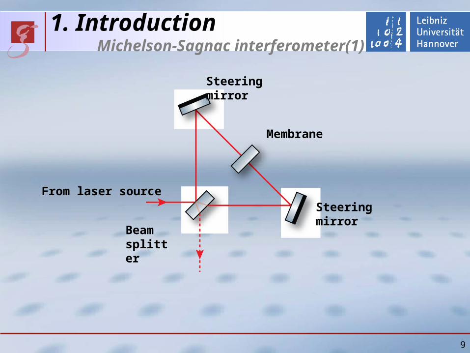
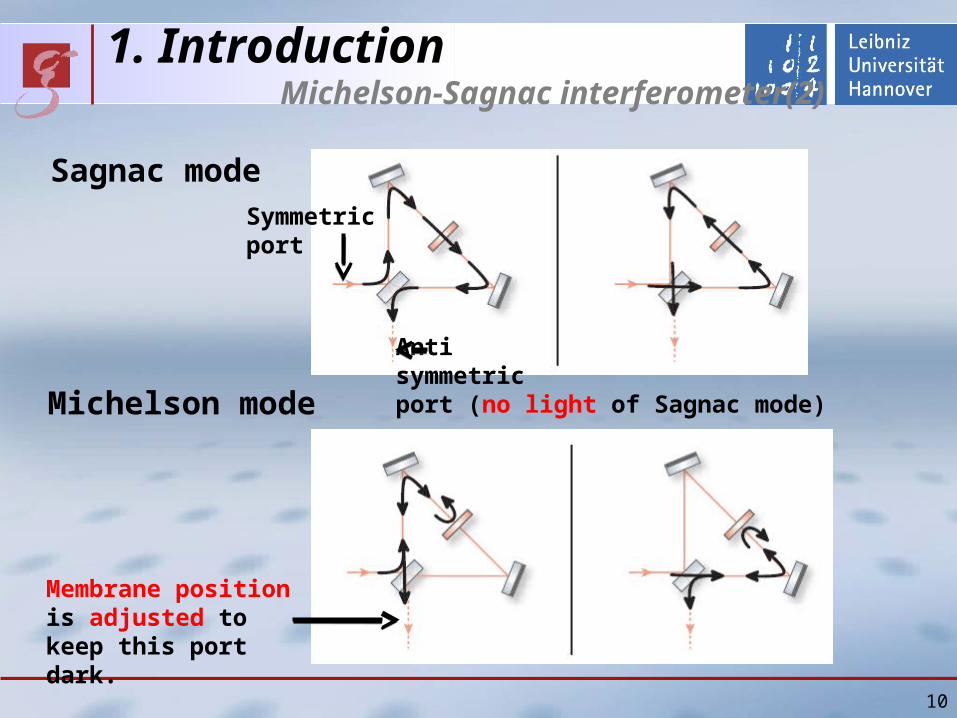
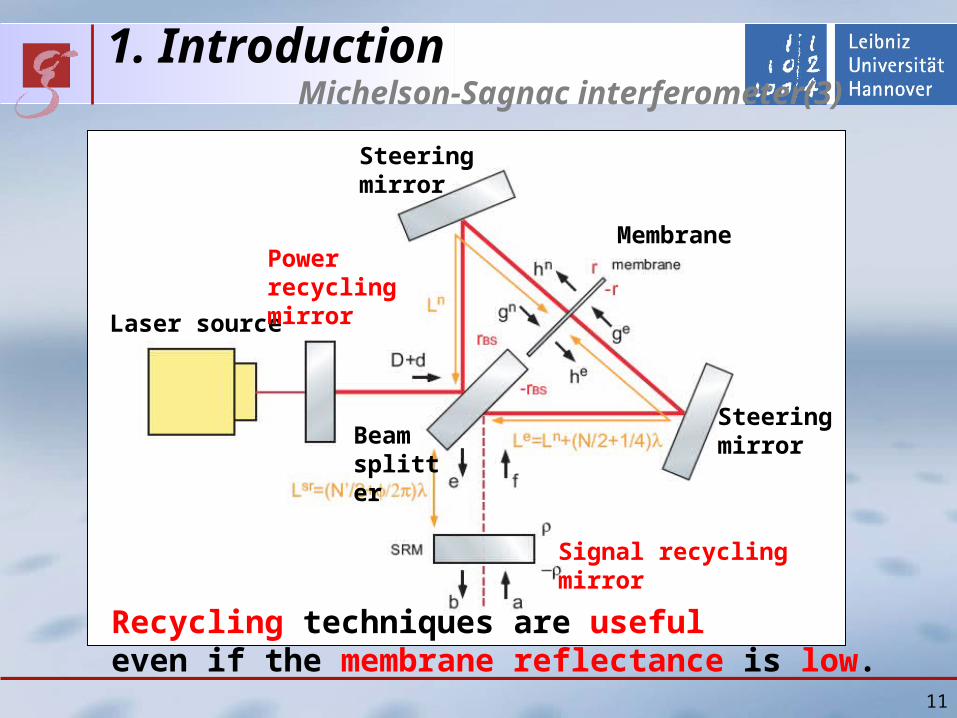
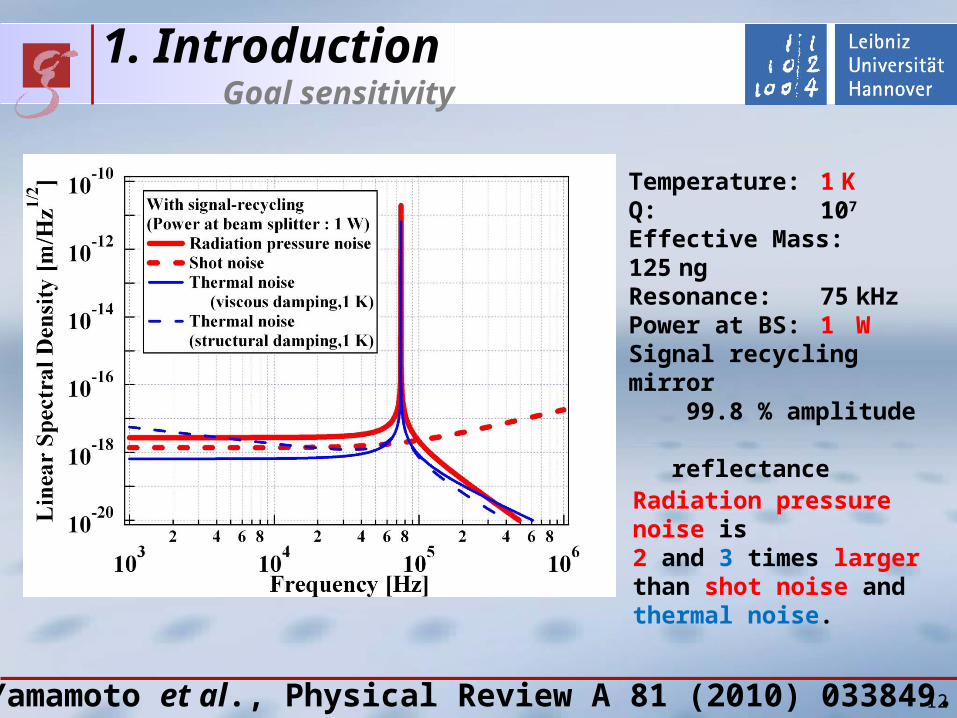
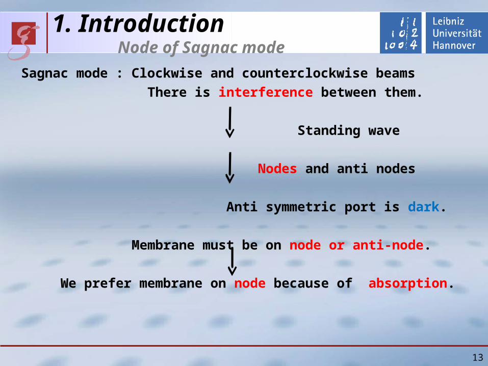
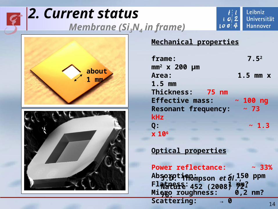
2 Current status Membrane (Si3N4 in frame)
14
Mechanical properties
frame 752 mm2 x 200 micromArea 15 mm x 15 mmThickness 75 nm Effective mass ~ 100 ngResonant frequency ~ 73 kHzQ ~ 13 x 106
Optical properties
Power reflectance ~ 33 Absorption le 150 ppmFlatness 1 nmMicro roughness 02 nmScattering rarr 0
JD Thompson et al Nature 452 (2008) 72-76
about1 mm
15
2 Current status Membrane (Si3N4 in frame)
Heat absorption in membrane (in Michelson-Sagnac interferometer)
Node of Sagnac mode (small absorption)
Anti node (large absorption)
Fitting Second polynomial(Physical mechanism is not clear yet)
First mode
16
2 Current status Membrane (Si3N4 in frame)
Heat absorption in membrane
Second mode
17
2 Current status Membrane (Si3N4 in frame)
Heat absorption in membrane
Fourth mode Temperature gradient
2 Current status Michelson-Sagnac interferometer
18
Without power and signal recycling
NdYAG laser EOM
Mode cleaner
Photodetector
Vacuum tank(10-6 mbar)
Photo detector(signal of membrane motion)
Membrane
2 Current status Inside vacuum tank
19
Membrane holder
Steering mirror
Steering mirror
Beam splitter
From lasersource
Antisymmeticport
20
2 Current status Measured power spectrum
On resonance Thermal noise
Off resonance Intensity noise
510-16 mrtHz
21
2 Current status Standard Quantum Limit on resonance
JILANIST group claims that their sensitivity is below Standard Quantum Limit (SQL)
JD Teufel et al Nature Nanotechnology 4 (2009) 820
4810-15 mrtHz
22
SQL
G Anetsberger et al Nature Physics 5 (2009) 909
Recent result from same group(arXiv10033752)
5710-16 mrtHz
2 Current status Standard Quantum Limit on resonance
Max-Planck-Institut (MPI) fuer Quantenoptik group also claims that their sensitivity is below Standard Quantum Limit (SQL)
23
Standard QuantumLimit (SQL) of NIST and MPI fuer Quantenoptik is constant around the resonance
Standard QuantumLimit (SQL) depends on (only) mechanical susceptibility
2 Current status Standard Quantum Limit on resonance
What is their definition of Standard Quantum Limit (SQL)
24
They compare off resonance sensitivity with Standard QuantumLimit (SQL) on resonance
Standard QuantumLimit (SQL) depends on (only) mechanical susceptibility
2 Current status Standard Quantum Limit on resonance
What is their difinition of Standard Quantum Limit (SQL)
25
Our sensitivity is also below Standard Quantum Limit (SQL) and better or comparable
510-16 mrtHz
2 Current status Standard Quantum Limit on resonance
3 Future work(1) Reduction of noise
(to observe off resonance thermal noise)
Laser intensity stabilization (in progress)
(2) Signal recycling
(3) Cryogenic apparatus (about 1K 3He evacuation)
Suspension
26
4 SummaryRadiation pressure noise measurement
with extremely light but translucent membrane
New topology Michelson-Sagnac interferometer
Goal sensitivity Nodes of Sagnac mode
Current status of experiment
Incident power dependence of resonant frequency
Operation without power and signal recycling
Current sensitivity (510-16 mrtHz)
Off resonance sensitivity
below Standard Quantum Limit (SQL) on resonance
Future work
Laser intensity stabilization
Cryogenic apparatus and so on 27
28
29
1 Introduction Radiation pressure noise
Vacuum
Frequency(Hz)
Sen
siti
vity
(r
tHz)
Radiation
pressure noise
Mirrorthermal noise
Advanced LIGO
30
1 Introduction Sizes of oscillators
TJ Kippenberg and K J Vahala Science 321 (2008) 1172
Resonant frequency
Effective Mass
Hz
MHz
kg
pg
31
Mechanical properties
frame 752 mm2 x 200 micromArea 15 mm x 15 mmThickness 75 nm Effective mass ~ 100 ngResonant frequency ~ 73 kHz
1 Introduction Membrane (Si3N4 in frame)
JD Thompson et al Nature 452 (2008) 72-76
32
GEO600 LIGO3 Adv LIGO3
Sakata1 Goszligler2 Corbitt3 Ours4
meff 1 kg 25 kg 10 kg 23 mg 05g 1 g 50 ng
P [kW] 10 10 830 12 0003 20 006
Pm [kWkg] 10 4 83 52103 6 20103 12109
Pm [kWkg] 3 13 29 48000 110 4500 5109
1 N Mavalvala Elba conference (2008)2 CM Mow-Lowry et al Journal of PhysicsCongerence Series 32 362-367 (2006)3 T Corbitt Elba conference (2008)4 JD Thompson et al Nature 452 72-76 (2008)
1 Introduction compare different approaches
2 Theoretical outlines
I will explain
Two differences from simple Michelson
(1)Radiation pressure noise on membrane
(2)Node of Sagnac mode
and goal sensitivity of our interferometer
33
2 Theoretical outlines Radiation pressure noise on membrane
34
Membrane
InterferenceInterference
Conclusion Radiation pressure noise is proportional to power reflectance of membraneeven if the membrane is at node of Sagnac mode
2 Current status Optical table
35
Laser source
Mode cleaner
Periscope
Vacuum tank
36
2 Current status Membrane holder
Stage
PZT with hole
Membrane frame
Membrane
3 Current status Michelson-Sagnac interferometer
37
Beam splitter
Membrane holder Steering
mirror
Steering mirror
From lasersource
2 Theoretical outlines Standart Quantum Limit (SQL)
SQL of Michelson-Sagnac interferometer (one membrane)
SQL of Fabry-Perot Michelson interferometer (four mirrors)
SQL of simple Michelson interferometer (two mirrors)
H Mechanical responce of one oscillatorOur conjucture SQL depends on number of mirrors (n)
38
39
3 Current status Calibration
Calibration (photo detector output vs displacement of membrane) is possible as like simple Michelson interferometer
Membrane displacement [nm]
Ph
oto
det
ecto
r o
utp
ut
po
wer
[a
u] Measured fringe
Fitting value
Measured results agree with fitting
Quater of wavelength
3 Current status Resonant frequencies of membrane
40
Fundamental mode (73kHz)
Frequency (kHz)
Am
pli
tud
e (d
B)
3 Current status Resonant frequencies of membrane
41
Difference between theory and measurement (~1)
Frequency [kHz]
Dif
fere
nce
bet
wee
n t
heo
ry
and
mea
sure
men
t [k
Hz]
75 nm
15 mm
42
bull Thermoelastic dampingrarr Estimation Q ~ 5 x 10⁷
bull Residual gas damping rarr Vacuum (~ 10-6 mbar)
3 Current status Q-values of membrane
bull Recoil loss rarr Estimation Q gt 107
bull Bulk loss rarr Unknownbull Loss on surface rarr Unknown
bull Our measurement Q ~ 13 x106 300 K
bull Measurement of other group Q ~ 1 x10⁷ 03 K BM Zwickl et al Applied Physics Letters 92(2008)103125
Time [sec]
Pressure [mbar]Q
MeasurementTheory
10-6
200 microm
75 nm
3 Current status Reflectance of membrane
Membrane
as etalon
Po
wer
ref
lect
ivit
y
43
Incident angle [degree]
P-polarized
S-polarized
44
vacuum systemto reach lt 10-6 mbar
actual pressurein experiment1510-7 mbar
backing pump pressure10-1 mbar not good enoughto use ducted vacuum
45
Q-measurementactual status of the table
laser preparation
membrane
periscopes
46
bull many unknown valuesbull had no verification for Harris results
rarr designed very sturdy mount
recent results
it should be sufficient to conserve Q of the small frame to be not limited
we will design a smaller mount for further experiment
recoil lossenergy transfer to membraneholder limits Q
osc
sup
sup
osc1-sup
1-osc
1osc QQQ
recoil
m
m
47
Q-measurementactual readout scheme
bull 106 periods per ringdowntime
rarr use lock in amplifier (variable filters)
our lock-in amp is too slow
rarr mixer shifts signal to some kHz
0f periodper energyloss
energy contained totalQ
ringdown time
48
Q-measurementactual readout scheme
106 periods per ringdowntime
rarr mix signal down (shift to lower freq)
Lock-in amp is too slow
rarr second mixer for some kHz
49
nonlinearity of the oscillationcomparison of our results to Harris`
Harris et al APL 92 (2008)our results
50
locking scheme for PR-cavityusing Pound Drever Hall signal
bull michelson acts as mirror
bull membrane-position dependent reflectivity (and phase)
51
locking scheme for Michelson interferometerusing Schnupp asymmetry
bull need different armlength
bull IFO reflecting carrierbull IFO partly transmitting sidebands
bull errorsignal in transmission
problems
bull need to preserve contrast
bull small asymmety
bull high modulation frequency
52
outlookfurther techniques
bull dual recycling
bull frequency stabilisation
with reference cavity
bull suspended interferometer
to isolate from seismic motion
(like Tokyo- group)
53
KryostatReduzierung thermischen Rauschens
Mehrstufiges Konzept (Zwiebelschalenmodell)
rarr Interferometer durch 4He gekuumlhlt
rarr Membran daruumlber hinaus durch 3He gekuumlhlt
Kryostat verursacht bdquoErschuumltterungenldquo
rarr Seismische Entkopplung des Interferometers
Thermisches Rauschen erfordert Kuumlhlung
54
Erwartete Empfindlichkeitfuumlr kryogene Temperaturen
rarr Schrotrauschen Faktor 2rarr therm Rauschen Faktor 3
Temperatur 1 KGuumlte 107
Effektive Masse 125 ngLeistung 400 WResonanz 50 kHz(optische Feder)
Weitere Option bull Signal Recycling (nur gegen Schrotrauschen)
62
Groszlige Uumlberschriftkleine Uumlberschrift
Text
63
2 Theoretical outlines
Three differences from simple Michelson
(1)Radiation pressure noise on membrane
(2)Node of Sagnac mode
(3)Optical spring
63
2 Theoretical outlines Optical spring (1)
Optical spring (without cavity) Light acts as spring
Radiation pressure on membrane depends on its position
Radiation pressure changes
resonant frequency of membrane
6464
InterferenceInterference
Membrane
Shift
2 Theoretical outlines Optical spring (2)
Phase of Michelson mode Shift
Sign of shift on right side is opposite to that on left side
Phase of Sagnac mode No shift
6565
Left side of membrane
Sagnac
Michelson
Right side of membrane
Shift by membrane
Shift by membrane
Michelson
Sagnac
2 Theoretical outlines Optical spring (3)
Interference Constructive (larger power) on right side
Destructive (smaller power) on left side
Radiation pressure on right side becomes larger
(Optical spring effect)
6666
Sagnac
Michelson
Shift by membrane
Shift by membrane
Michelson
Sagnac
Left side of membrane Right side of membrane
2 Theoretical outlines Goal sensitivity
6767
Temperature 1 KQ 107
Effective Mass 125 ngPower at BS 400 WResonance 75 kHz(with optical spring)Resonance 50 kHz(without optical spring)
Shot noise Factor 2Thermal noise Factor 3
Option Signal Recycling 99 power reflectance Power at BS about 1W P
ow
er s
pec
tru
m d
ensi
ty [
mr
tHz]
Frequency[kHz]
Shot noiseQuantum noiseThermal noise
Without signal recycling
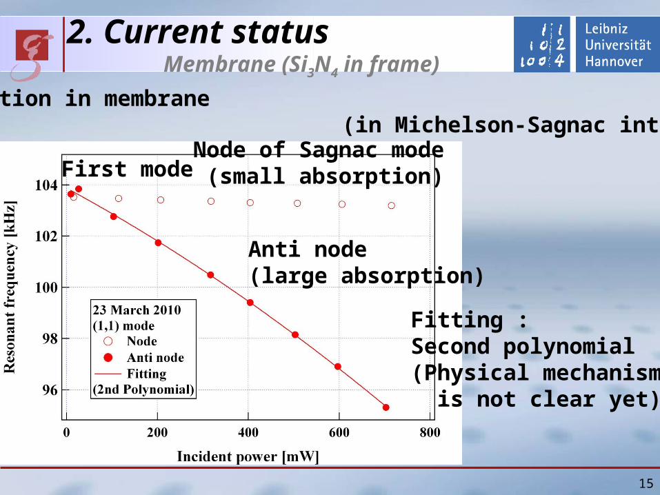
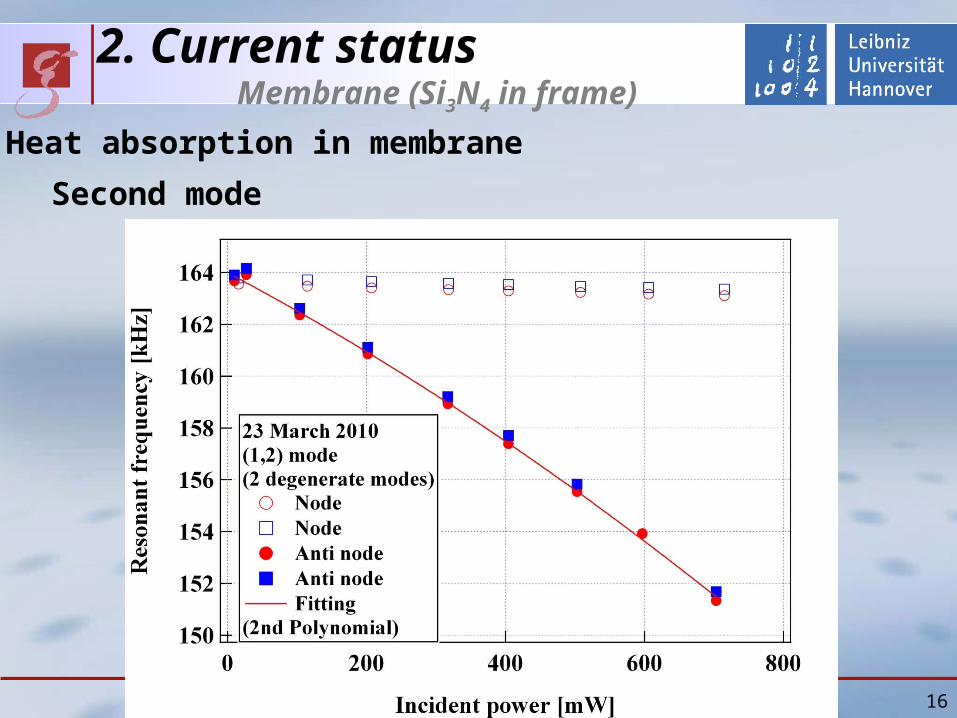
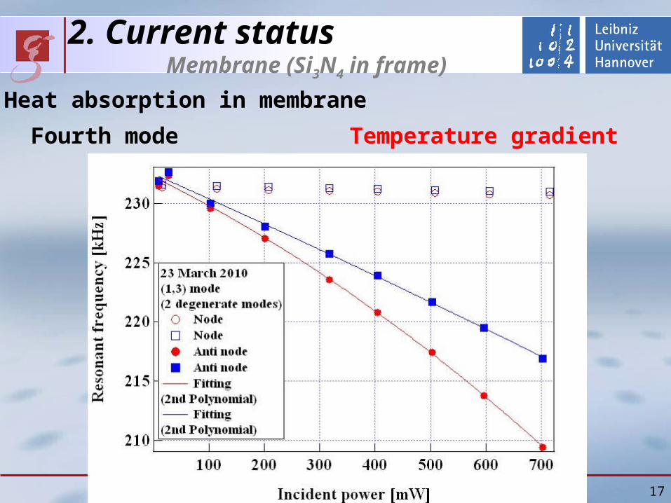
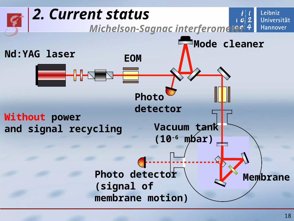
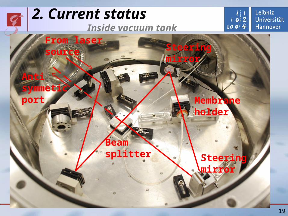
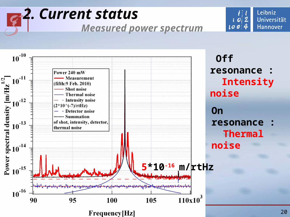
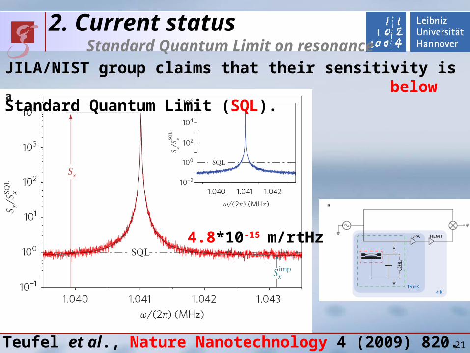
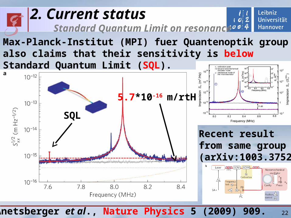
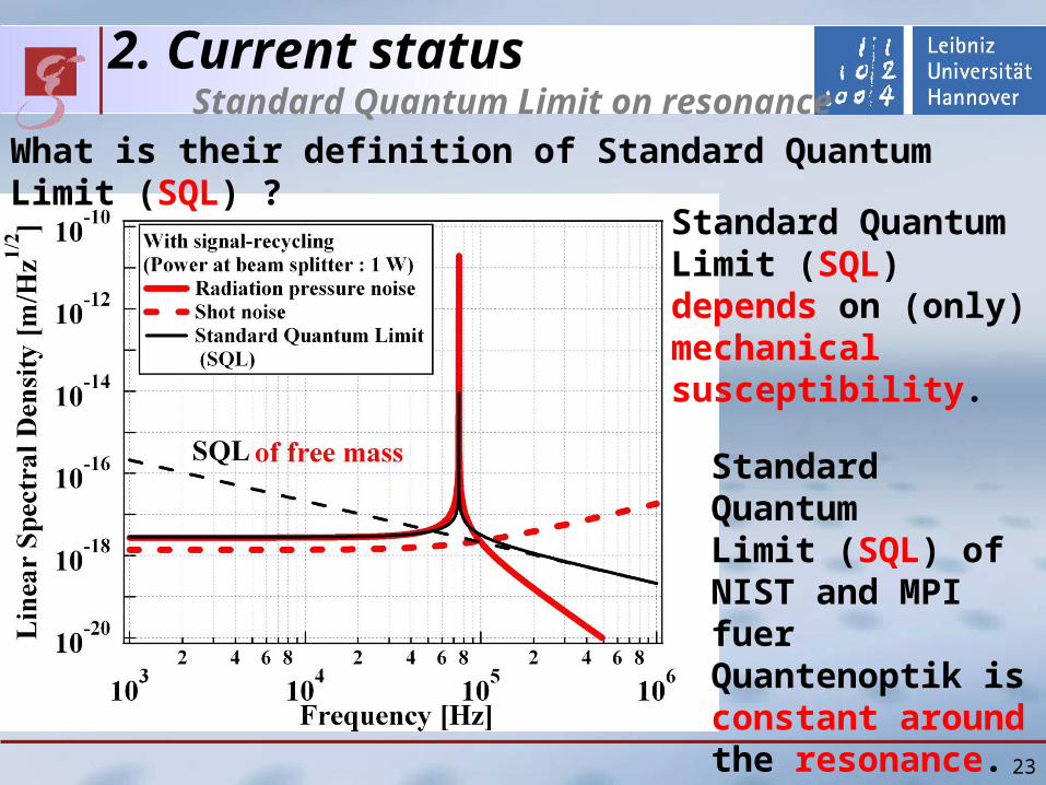
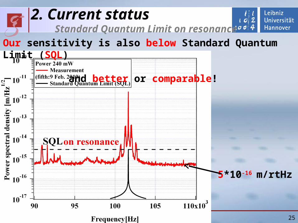
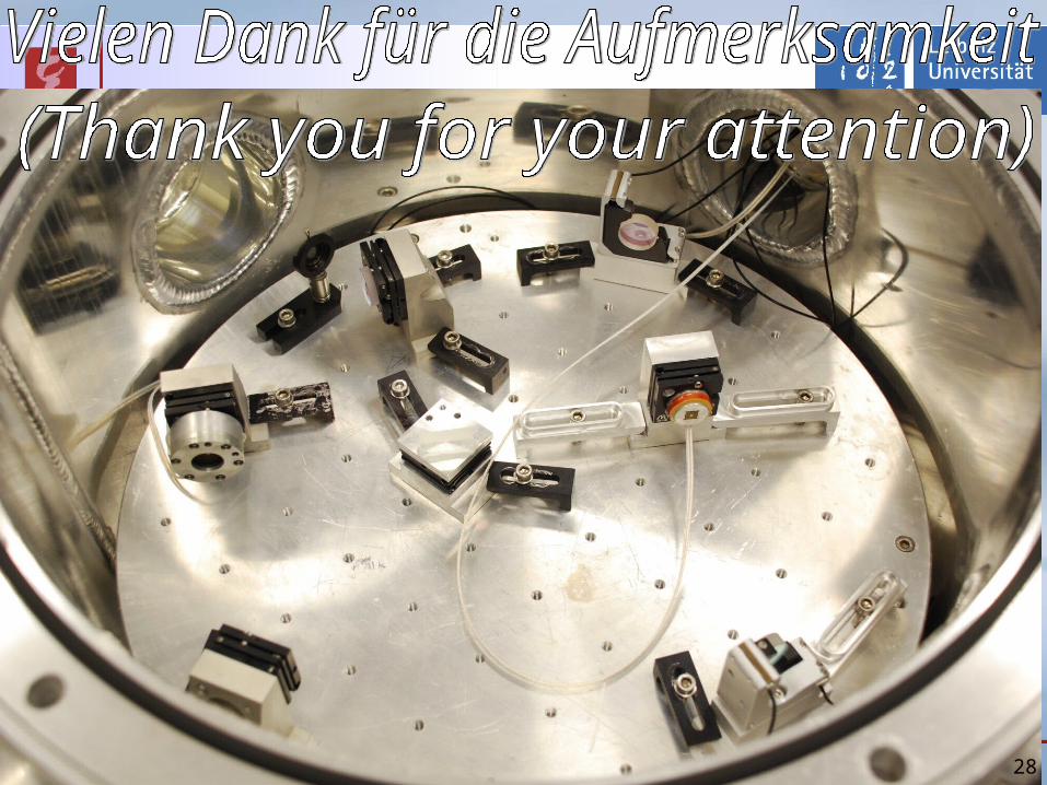
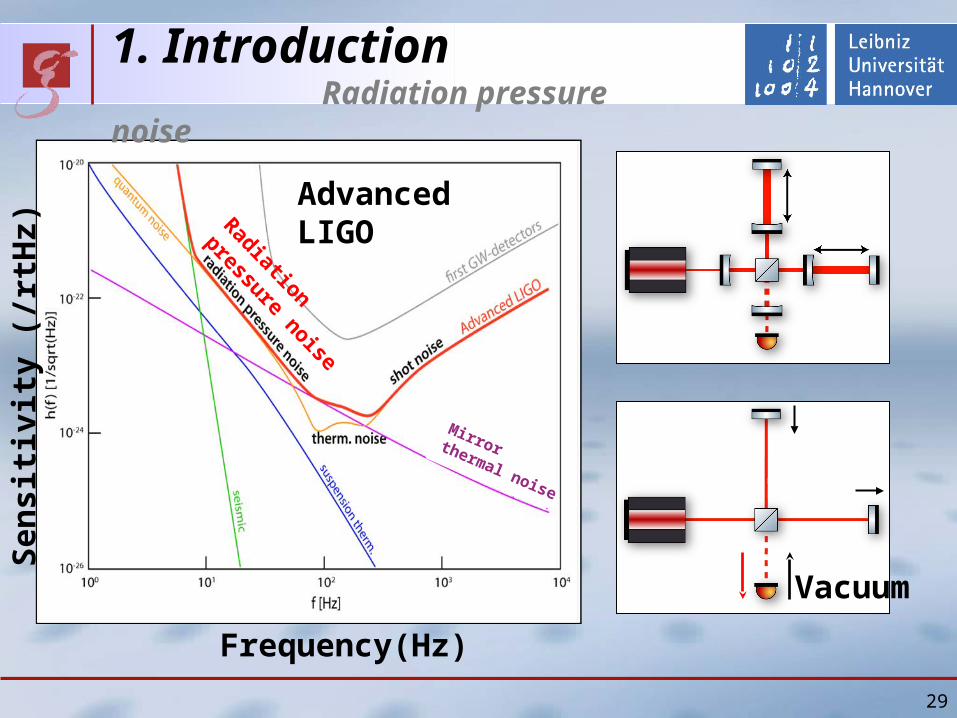
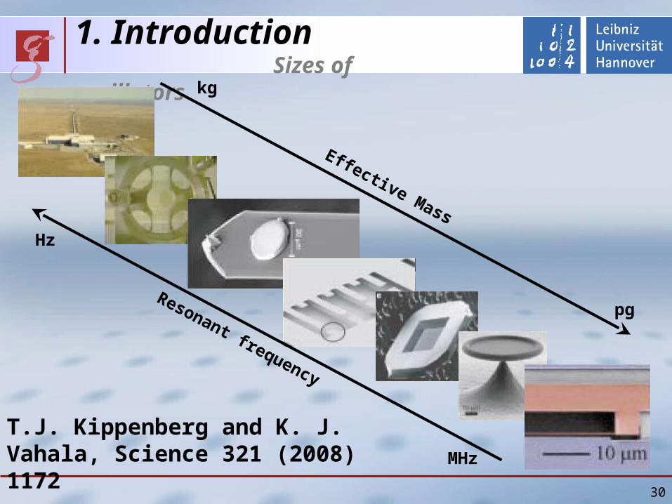
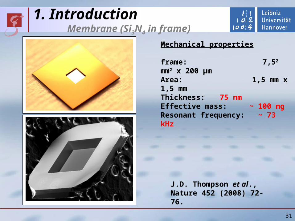
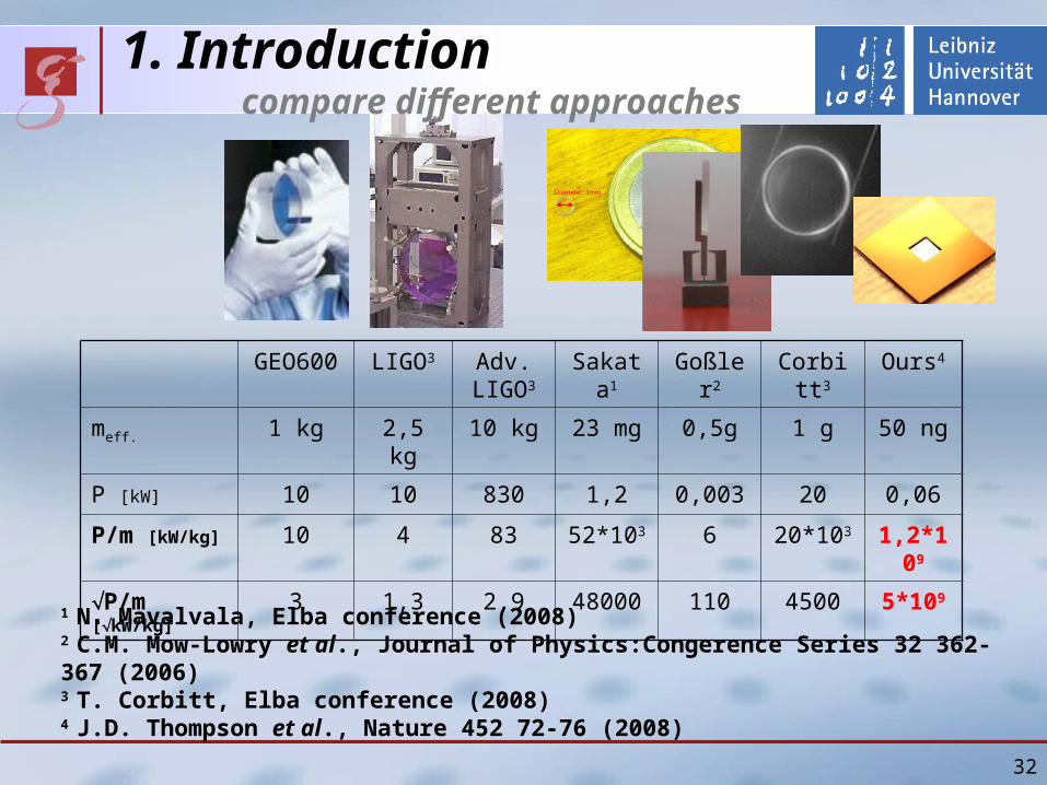
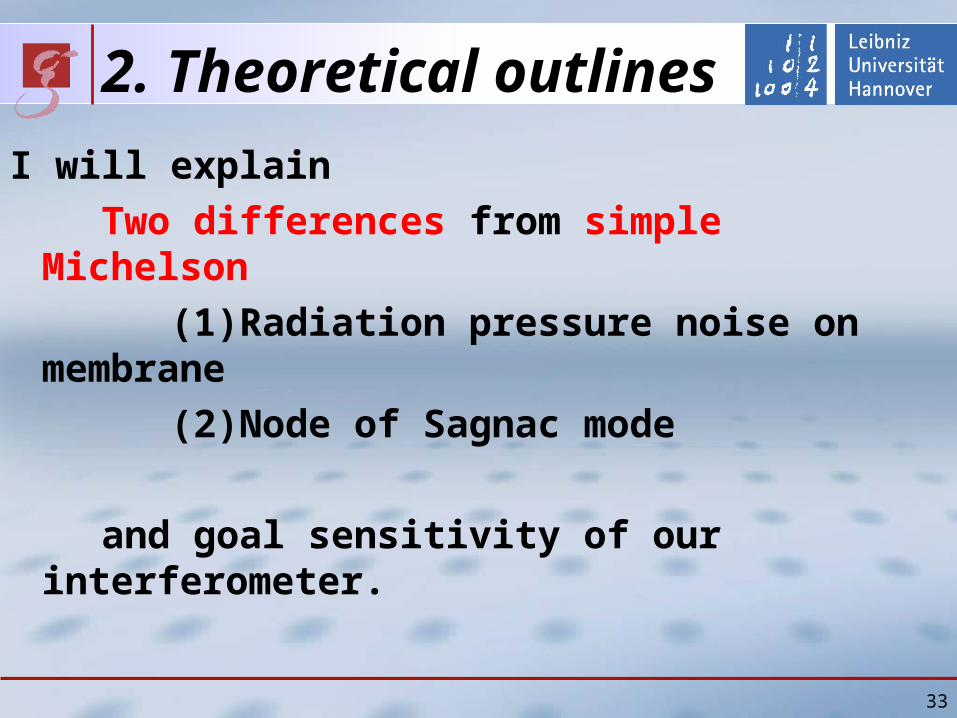
2 Theoretical outlines
I will explain
Two differences from simple Michelson
(1)Radiation pressure noise on membrane
(2)Node of Sagnac mode
and goal sensitivity of our interferometer
33
2 Theoretical outlines Radiation pressure noise on membrane
34
Membrane
InterferenceInterference
Conclusion Radiation pressure noise is proportional to power reflectance of membraneeven if the membrane is at node of Sagnac mode
2 Current status Optical table
35
Laser source
Mode cleaner
Periscope
Vacuum tank
36
2 Current status Membrane holder
Stage
PZT with hole
Membrane frame
Membrane
3 Current status Michelson-Sagnac interferometer
37
Beam splitter
Membrane holder Steering
mirror
Steering mirror
From lasersource
2 Theoretical outlines Standart Quantum Limit (SQL)
SQL of Michelson-Sagnac interferometer (one membrane)
SQL of Fabry-Perot Michelson interferometer (four mirrors)
SQL of simple Michelson interferometer (two mirrors)
H Mechanical responce of one oscillatorOur conjucture SQL depends on number of mirrors (n)
38
39
3 Current status Calibration
Calibration (photo detector output vs displacement of membrane) is possible as like simple Michelson interferometer
Membrane displacement [nm]
Ph
oto
det
ecto
r o
utp
ut
po
wer
[a
u] Measured fringe
Fitting value
Measured results agree with fitting
Quater of wavelength
3 Current status Resonant frequencies of membrane
40
Fundamental mode (73kHz)
Frequency (kHz)
Am
pli
tud
e (d
B)
3 Current status Resonant frequencies of membrane
41
Difference between theory and measurement (~1)
Frequency [kHz]
Dif
fere
nce
bet
wee
n t
heo
ry
and
mea
sure
men
t [k
Hz]
75 nm
15 mm
42
bull Thermoelastic dampingrarr Estimation Q ~ 5 x 10⁷
bull Residual gas damping rarr Vacuum (~ 10-6 mbar)
3 Current status Q-values of membrane
bull Recoil loss rarr Estimation Q gt 107
bull Bulk loss rarr Unknownbull Loss on surface rarr Unknown
bull Our measurement Q ~ 13 x106 300 K
bull Measurement of other group Q ~ 1 x10⁷ 03 K BM Zwickl et al Applied Physics Letters 92(2008)103125
Time [sec]
Pressure [mbar]Q
MeasurementTheory
10-6
200 microm
75 nm
3 Current status Reflectance of membrane
Membrane
as etalon
Po
wer
ref
lect
ivit
y
43
Incident angle [degree]
P-polarized
S-polarized
44
vacuum systemto reach lt 10-6 mbar
actual pressurein experiment1510-7 mbar
backing pump pressure10-1 mbar not good enoughto use ducted vacuum
45
Q-measurementactual status of the table
laser preparation
membrane
periscopes
46
bull many unknown valuesbull had no verification for Harris results
rarr designed very sturdy mount
recent results
it should be sufficient to conserve Q of the small frame to be not limited
we will design a smaller mount for further experiment
recoil lossenergy transfer to membraneholder limits Q
osc
sup
sup
osc1-sup
1-osc
1osc QQQ
recoil
m
m
47
Q-measurementactual readout scheme
bull 106 periods per ringdowntime
rarr use lock in amplifier (variable filters)
our lock-in amp is too slow
rarr mixer shifts signal to some kHz
0f periodper energyloss
energy contained totalQ
ringdown time
48
Q-measurementactual readout scheme
106 periods per ringdowntime
rarr mix signal down (shift to lower freq)
Lock-in amp is too slow
rarr second mixer for some kHz
49
nonlinearity of the oscillationcomparison of our results to Harris`
Harris et al APL 92 (2008)our results
50
locking scheme for PR-cavityusing Pound Drever Hall signal
bull michelson acts as mirror
bull membrane-position dependent reflectivity (and phase)
51
locking scheme for Michelson interferometerusing Schnupp asymmetry
bull need different armlength
bull IFO reflecting carrierbull IFO partly transmitting sidebands
bull errorsignal in transmission
problems
bull need to preserve contrast
bull small asymmety
bull high modulation frequency
52
outlookfurther techniques
bull dual recycling
bull frequency stabilisation
with reference cavity
bull suspended interferometer
to isolate from seismic motion
(like Tokyo- group)
53
KryostatReduzierung thermischen Rauschens
Mehrstufiges Konzept (Zwiebelschalenmodell)
rarr Interferometer durch 4He gekuumlhlt
rarr Membran daruumlber hinaus durch 3He gekuumlhlt
Kryostat verursacht bdquoErschuumltterungenldquo
rarr Seismische Entkopplung des Interferometers
Thermisches Rauschen erfordert Kuumlhlung
54
Erwartete Empfindlichkeitfuumlr kryogene Temperaturen
rarr Schrotrauschen Faktor 2rarr therm Rauschen Faktor 3
Temperatur 1 KGuumlte 107
Effektive Masse 125 ngLeistung 400 WResonanz 50 kHz(optische Feder)
Weitere Option bull Signal Recycling (nur gegen Schrotrauschen)
62
Groszlige Uumlberschriftkleine Uumlberschrift
Text
63
2 Theoretical outlines
Three differences from simple Michelson
(1)Radiation pressure noise on membrane
(2)Node of Sagnac mode
(3)Optical spring
63
2 Theoretical outlines Optical spring (1)
Optical spring (without cavity) Light acts as spring
Radiation pressure on membrane depends on its position
Radiation pressure changes
resonant frequency of membrane
6464
InterferenceInterference
Membrane
Shift
2 Theoretical outlines Optical spring (2)
Phase of Michelson mode Shift
Sign of shift on right side is opposite to that on left side
Phase of Sagnac mode No shift
6565
Left side of membrane
Sagnac
Michelson
Right side of membrane
Shift by membrane
Shift by membrane
Michelson
Sagnac
2 Theoretical outlines Optical spring (3)
Interference Constructive (larger power) on right side
Destructive (smaller power) on left side
Radiation pressure on right side becomes larger
(Optical spring effect)
6666
Sagnac
Michelson
Shift by membrane
Shift by membrane
Michelson
Sagnac
Left side of membrane Right side of membrane
2 Theoretical outlines Goal sensitivity
6767
Temperature 1 KQ 107
Effective Mass 125 ngPower at BS 400 WResonance 75 kHz(with optical spring)Resonance 50 kHz(without optical spring)
Shot noise Factor 2Thermal noise Factor 3
Option Signal Recycling 99 power reflectance Power at BS about 1W P
ow
er s
pec
tru
m d
ensi
ty [
mr
tHz]
Frequency[kHz]
Shot noiseQuantum noiseThermal noise
Without signal recycling
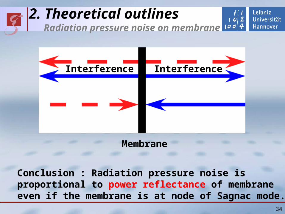
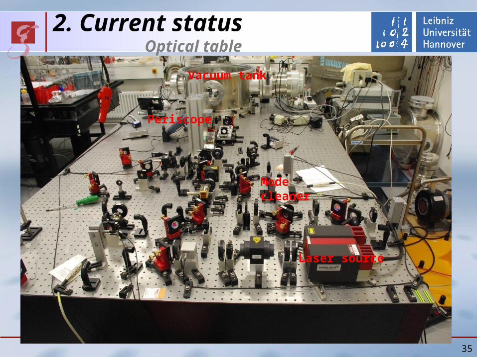
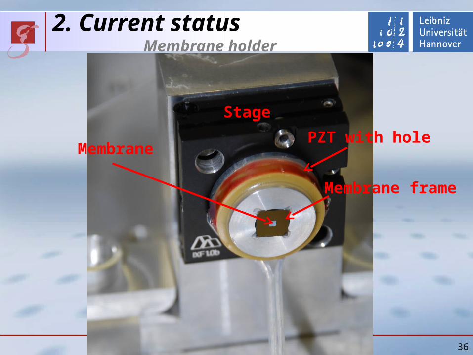
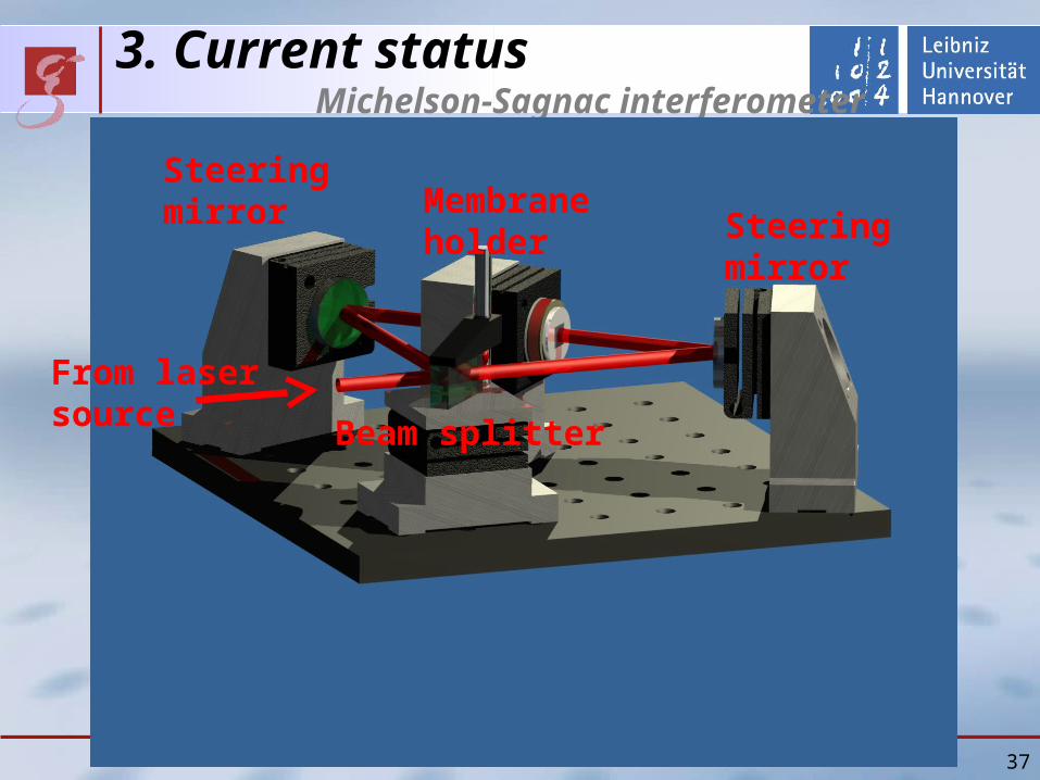
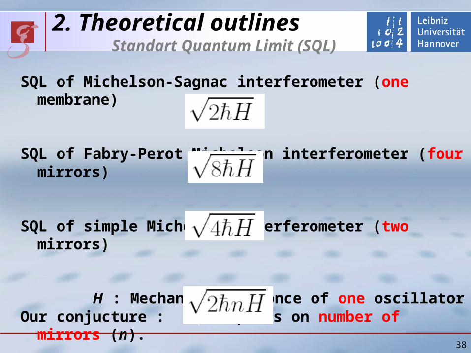
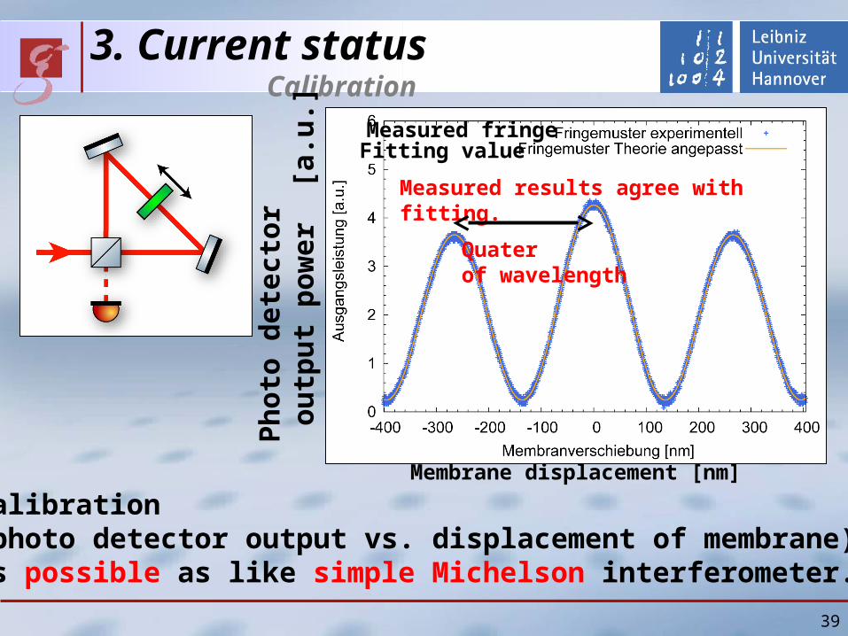
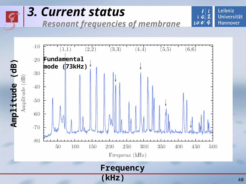
3 Current status Resonant frequencies of membrane
40
Fundamental mode (73kHz)
Frequency (kHz)
Am
pli
tud
e (d
B)
3 Current status Resonant frequencies of membrane
41
Difference between theory and measurement (~1)
Frequency [kHz]
Dif
fere
nce
bet
wee
n t
heo
ry
and
mea
sure
men
t [k
Hz]
75 nm
15 mm
42
bull Thermoelastic dampingrarr Estimation Q ~ 5 x 10⁷
bull Residual gas damping rarr Vacuum (~ 10-6 mbar)
3 Current status Q-values of membrane
bull Recoil loss rarr Estimation Q gt 107
bull Bulk loss rarr Unknownbull Loss on surface rarr Unknown
bull Our measurement Q ~ 13 x106 300 K
bull Measurement of other group Q ~ 1 x10⁷ 03 K BM Zwickl et al Applied Physics Letters 92(2008)103125
Time [sec]
Pressure [mbar]Q
MeasurementTheory
10-6
200 microm
75 nm
3 Current status Reflectance of membrane
Membrane
as etalon
Po
wer
ref
lect
ivit
y
43
Incident angle [degree]
P-polarized
S-polarized
44
vacuum systemto reach lt 10-6 mbar
actual pressurein experiment1510-7 mbar
backing pump pressure10-1 mbar not good enoughto use ducted vacuum
45
Q-measurementactual status of the table
laser preparation
membrane
periscopes
46
bull many unknown valuesbull had no verification for Harris results
rarr designed very sturdy mount
recent results
it should be sufficient to conserve Q of the small frame to be not limited
we will design a smaller mount for further experiment
recoil lossenergy transfer to membraneholder limits Q
osc
sup
sup
osc1-sup
1-osc
1osc QQQ
recoil
m
m
47
Q-measurementactual readout scheme
bull 106 periods per ringdowntime
rarr use lock in amplifier (variable filters)
our lock-in amp is too slow
rarr mixer shifts signal to some kHz
0f periodper energyloss
energy contained totalQ
ringdown time
48
Q-measurementactual readout scheme
106 periods per ringdowntime
rarr mix signal down (shift to lower freq)
Lock-in amp is too slow
rarr second mixer for some kHz
49
nonlinearity of the oscillationcomparison of our results to Harris`
Harris et al APL 92 (2008)our results
50
locking scheme for PR-cavityusing Pound Drever Hall signal
bull michelson acts as mirror
bull membrane-position dependent reflectivity (and phase)
51
locking scheme for Michelson interferometerusing Schnupp asymmetry
bull need different armlength
bull IFO reflecting carrierbull IFO partly transmitting sidebands
bull errorsignal in transmission
problems
bull need to preserve contrast
bull small asymmety
bull high modulation frequency
52
outlookfurther techniques
bull dual recycling
bull frequency stabilisation
with reference cavity
bull suspended interferometer
to isolate from seismic motion
(like Tokyo- group)
53
KryostatReduzierung thermischen Rauschens
Mehrstufiges Konzept (Zwiebelschalenmodell)
rarr Interferometer durch 4He gekuumlhlt
rarr Membran daruumlber hinaus durch 3He gekuumlhlt
Kryostat verursacht bdquoErschuumltterungenldquo
rarr Seismische Entkopplung des Interferometers
Thermisches Rauschen erfordert Kuumlhlung
54
Erwartete Empfindlichkeitfuumlr kryogene Temperaturen
rarr Schrotrauschen Faktor 2rarr therm Rauschen Faktor 3
Temperatur 1 KGuumlte 107
Effektive Masse 125 ngLeistung 400 WResonanz 50 kHz(optische Feder)
Weitere Option bull Signal Recycling (nur gegen Schrotrauschen)
62
Groszlige Uumlberschriftkleine Uumlberschrift
Text
63
2 Theoretical outlines
Three differences from simple Michelson
(1)Radiation pressure noise on membrane
(2)Node of Sagnac mode
(3)Optical spring
63
2 Theoretical outlines Optical spring (1)
Optical spring (without cavity) Light acts as spring
Radiation pressure on membrane depends on its position
Radiation pressure changes
resonant frequency of membrane
6464
InterferenceInterference
Membrane
Shift
2 Theoretical outlines Optical spring (2)
Phase of Michelson mode Shift
Sign of shift on right side is opposite to that on left side
Phase of Sagnac mode No shift
6565
Left side of membrane
Sagnac
Michelson
Right side of membrane
Shift by membrane
Shift by membrane
Michelson
Sagnac
2 Theoretical outlines Optical spring (3)
Interference Constructive (larger power) on right side
Destructive (smaller power) on left side
Radiation pressure on right side becomes larger
(Optical spring effect)
6666
Sagnac
Michelson
Shift by membrane
Shift by membrane
Michelson
Sagnac
Left side of membrane Right side of membrane
2 Theoretical outlines Goal sensitivity
6767
Temperature 1 KQ 107
Effective Mass 125 ngPower at BS 400 WResonance 75 kHz(with optical spring)Resonance 50 kHz(without optical spring)
Shot noise Factor 2Thermal noise Factor 3
Option Signal Recycling 99 power reflectance Power at BS about 1W P
ow
er s
pec
tru
m d
ensi
ty [
mr
tHz]
Frequency[kHz]
Shot noiseQuantum noiseThermal noise
Without signal recycling
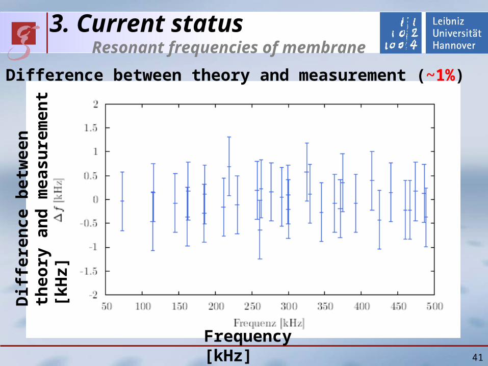
3 Current status Resonant frequencies of membrane
41
Difference between theory and measurement (~1)
Frequency [kHz]
Dif
fere
nce
bet
wee
n t
heo
ry
and
mea
sure
men
t [k
Hz]
75 nm
15 mm
42
bull Thermoelastic dampingrarr Estimation Q ~ 5 x 10⁷
bull Residual gas damping rarr Vacuum (~ 10-6 mbar)
3 Current status Q-values of membrane
bull Recoil loss rarr Estimation Q gt 107
bull Bulk loss rarr Unknownbull Loss on surface rarr Unknown
bull Our measurement Q ~ 13 x106 300 K
bull Measurement of other group Q ~ 1 x10⁷ 03 K BM Zwickl et al Applied Physics Letters 92(2008)103125
Time [sec]
Pressure [mbar]Q
MeasurementTheory
10-6
200 microm
75 nm
3 Current status Reflectance of membrane
Membrane
as etalon
Po
wer
ref
lect
ivit
y
43
Incident angle [degree]
P-polarized
S-polarized
44
vacuum systemto reach lt 10-6 mbar
actual pressurein experiment1510-7 mbar
backing pump pressure10-1 mbar not good enoughto use ducted vacuum
45
Q-measurementactual status of the table
laser preparation
membrane
periscopes
46
bull many unknown valuesbull had no verification for Harris results
rarr designed very sturdy mount
recent results
it should be sufficient to conserve Q of the small frame to be not limited
we will design a smaller mount for further experiment
recoil lossenergy transfer to membraneholder limits Q
osc
sup
sup
osc1-sup
1-osc
1osc QQQ
recoil
m
m
47
Q-measurementactual readout scheme
bull 106 periods per ringdowntime
rarr use lock in amplifier (variable filters)
our lock-in amp is too slow
rarr mixer shifts signal to some kHz
0f periodper energyloss
energy contained totalQ
ringdown time
48
Q-measurementactual readout scheme
106 periods per ringdowntime
rarr mix signal down (shift to lower freq)
Lock-in amp is too slow
rarr second mixer for some kHz
49
nonlinearity of the oscillationcomparison of our results to Harris`
Harris et al APL 92 (2008)our results
50
locking scheme for PR-cavityusing Pound Drever Hall signal
bull michelson acts as mirror
bull membrane-position dependent reflectivity (and phase)
51
locking scheme for Michelson interferometerusing Schnupp asymmetry
bull need different armlength
bull IFO reflecting carrierbull IFO partly transmitting sidebands
bull errorsignal in transmission
problems
bull need to preserve contrast
bull small asymmety
bull high modulation frequency
52
outlookfurther techniques
bull dual recycling
bull frequency stabilisation
with reference cavity
bull suspended interferometer
to isolate from seismic motion
(like Tokyo- group)
53
KryostatReduzierung thermischen Rauschens
Mehrstufiges Konzept (Zwiebelschalenmodell)
rarr Interferometer durch 4He gekuumlhlt
rarr Membran daruumlber hinaus durch 3He gekuumlhlt
Kryostat verursacht bdquoErschuumltterungenldquo
rarr Seismische Entkopplung des Interferometers
Thermisches Rauschen erfordert Kuumlhlung
54
Erwartete Empfindlichkeitfuumlr kryogene Temperaturen
rarr Schrotrauschen Faktor 2rarr therm Rauschen Faktor 3
Temperatur 1 KGuumlte 107
Effektive Masse 125 ngLeistung 400 WResonanz 50 kHz(optische Feder)
Weitere Option bull Signal Recycling (nur gegen Schrotrauschen)
62
Groszlige Uumlberschriftkleine Uumlberschrift
Text
63
2 Theoretical outlines
Three differences from simple Michelson
(1)Radiation pressure noise on membrane
(2)Node of Sagnac mode
(3)Optical spring
63
2 Theoretical outlines Optical spring (1)
Optical spring (without cavity) Light acts as spring
Radiation pressure on membrane depends on its position
Radiation pressure changes
resonant frequency of membrane
6464
InterferenceInterference
Membrane
Shift
2 Theoretical outlines Optical spring (2)
Phase of Michelson mode Shift
Sign of shift on right side is opposite to that on left side
Phase of Sagnac mode No shift
6565
Left side of membrane
Sagnac
Michelson
Right side of membrane
Shift by membrane
Shift by membrane
Michelson
Sagnac
2 Theoretical outlines Optical spring (3)
Interference Constructive (larger power) on right side
Destructive (smaller power) on left side
Radiation pressure on right side becomes larger
(Optical spring effect)
6666
Sagnac
Michelson
Shift by membrane
Shift by membrane
Michelson
Sagnac
Left side of membrane Right side of membrane
2 Theoretical outlines Goal sensitivity
6767
Temperature 1 KQ 107
Effective Mass 125 ngPower at BS 400 WResonance 75 kHz(with optical spring)Resonance 50 kHz(without optical spring)
Shot noise Factor 2Thermal noise Factor 3
Option Signal Recycling 99 power reflectance Power at BS about 1W P
ow
er s
pec
tru
m d
ensi
ty [
mr
tHz]
Frequency[kHz]
Shot noiseQuantum noiseThermal noise
Without signal recycling
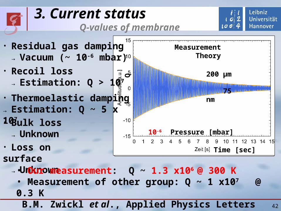
75 nm
15 mm
42
bull Thermoelastic dampingrarr Estimation Q ~ 5 x 10⁷
bull Residual gas damping rarr Vacuum (~ 10-6 mbar)
3 Current status Q-values of membrane
bull Recoil loss rarr Estimation Q gt 107
bull Bulk loss rarr Unknownbull Loss on surface rarr Unknown
bull Our measurement Q ~ 13 x106 300 K
bull Measurement of other group Q ~ 1 x10⁷ 03 K BM Zwickl et al Applied Physics Letters 92(2008)103125
Time [sec]
Pressure [mbar]Q
MeasurementTheory
10-6
200 microm
75 nm
3 Current status Reflectance of membrane
Membrane
as etalon
Po
wer
ref
lect
ivit
y
43
Incident angle [degree]
P-polarized
S-polarized
44
vacuum systemto reach lt 10-6 mbar
actual pressurein experiment1510-7 mbar
backing pump pressure10-1 mbar not good enoughto use ducted vacuum
45
Q-measurementactual status of the table
laser preparation
membrane
periscopes
46
bull many unknown valuesbull had no verification for Harris results
rarr designed very sturdy mount
recent results
it should be sufficient to conserve Q of the small frame to be not limited
we will design a smaller mount for further experiment
recoil lossenergy transfer to membraneholder limits Q
osc
sup
sup
osc1-sup
1-osc
1osc QQQ
recoil
m
m
47
Q-measurementactual readout scheme
bull 106 periods per ringdowntime
rarr use lock in amplifier (variable filters)
our lock-in amp is too slow
rarr mixer shifts signal to some kHz
0f periodper energyloss
energy contained totalQ
ringdown time
48
Q-measurementactual readout scheme
106 periods per ringdowntime
rarr mix signal down (shift to lower freq)
Lock-in amp is too slow
rarr second mixer for some kHz
49
nonlinearity of the oscillationcomparison of our results to Harris`
Harris et al APL 92 (2008)our results
50
locking scheme for PR-cavityusing Pound Drever Hall signal
bull michelson acts as mirror
bull membrane-position dependent reflectivity (and phase)
51
locking scheme for Michelson interferometerusing Schnupp asymmetry
bull need different armlength
bull IFO reflecting carrierbull IFO partly transmitting sidebands
bull errorsignal in transmission
problems
bull need to preserve contrast
bull small asymmety
bull high modulation frequency
52
outlookfurther techniques
bull dual recycling
bull frequency stabilisation
with reference cavity
bull suspended interferometer
to isolate from seismic motion
(like Tokyo- group)
53
KryostatReduzierung thermischen Rauschens
Mehrstufiges Konzept (Zwiebelschalenmodell)
rarr Interferometer durch 4He gekuumlhlt
rarr Membran daruumlber hinaus durch 3He gekuumlhlt
Kryostat verursacht bdquoErschuumltterungenldquo
rarr Seismische Entkopplung des Interferometers
Thermisches Rauschen erfordert Kuumlhlung
54
Erwartete Empfindlichkeitfuumlr kryogene Temperaturen
rarr Schrotrauschen Faktor 2rarr therm Rauschen Faktor 3
Temperatur 1 KGuumlte 107
Effektive Masse 125 ngLeistung 400 WResonanz 50 kHz(optische Feder)
Weitere Option bull Signal Recycling (nur gegen Schrotrauschen)
62
Groszlige Uumlberschriftkleine Uumlberschrift
Text
63
2 Theoretical outlines
Three differences from simple Michelson
(1)Radiation pressure noise on membrane
(2)Node of Sagnac mode
(3)Optical spring
63
2 Theoretical outlines Optical spring (1)
Optical spring (without cavity) Light acts as spring
Radiation pressure on membrane depends on its position
Radiation pressure changes
resonant frequency of membrane
6464
InterferenceInterference
Membrane
Shift
2 Theoretical outlines Optical spring (2)
Phase of Michelson mode Shift
Sign of shift on right side is opposite to that on left side
Phase of Sagnac mode No shift
6565
Left side of membrane
Sagnac
Michelson
Right side of membrane
Shift by membrane
Shift by membrane
Michelson
Sagnac
2 Theoretical outlines Optical spring (3)
Interference Constructive (larger power) on right side
Destructive (smaller power) on left side
Radiation pressure on right side becomes larger
(Optical spring effect)
6666
Sagnac
Michelson
Shift by membrane
Shift by membrane
Michelson
Sagnac
Left side of membrane Right side of membrane
2 Theoretical outlines Goal sensitivity
6767
Temperature 1 KQ 107
Effective Mass 125 ngPower at BS 400 WResonance 75 kHz(with optical spring)Resonance 50 kHz(without optical spring)
Shot noise Factor 2Thermal noise Factor 3
Option Signal Recycling 99 power reflectance Power at BS about 1W P
ow
er s
pec
tru
m d
ensi
ty [
mr
tHz]
Frequency[kHz]
Shot noiseQuantum noiseThermal noise
Without signal recycling
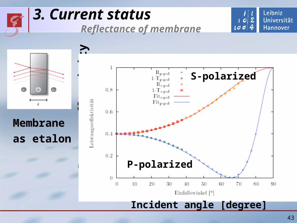
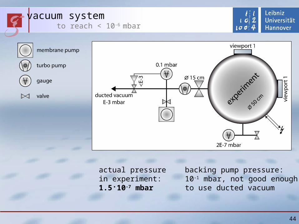
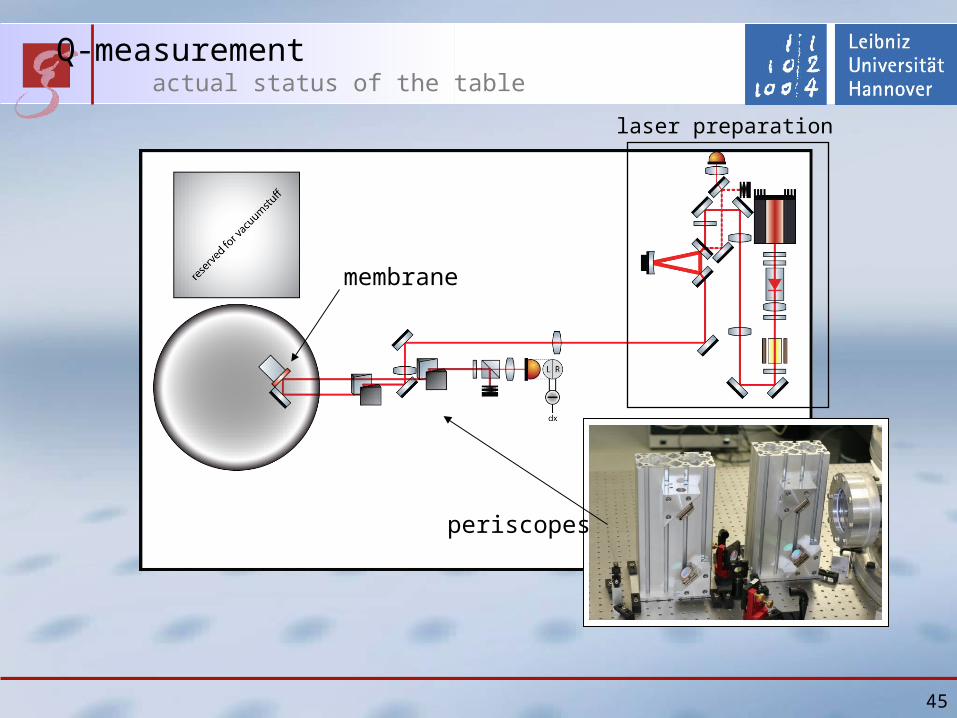
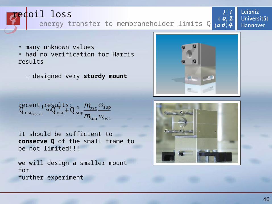
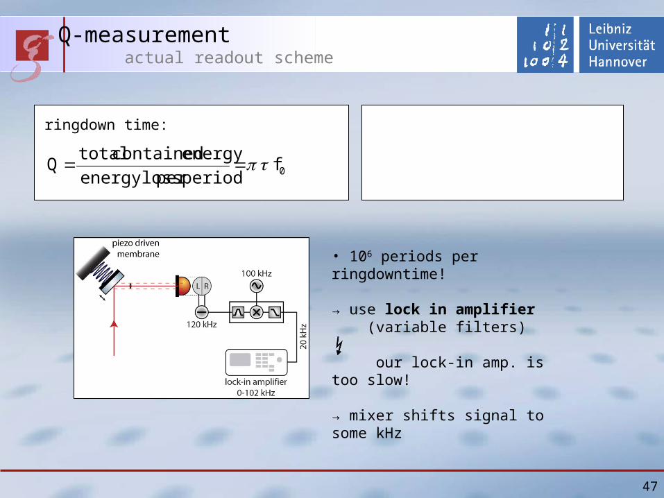
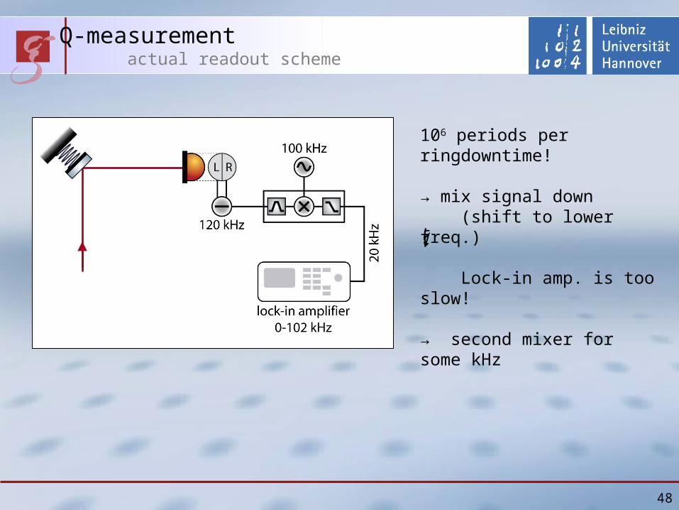
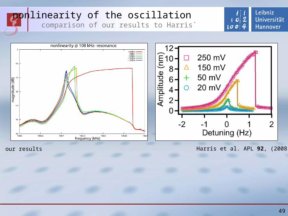
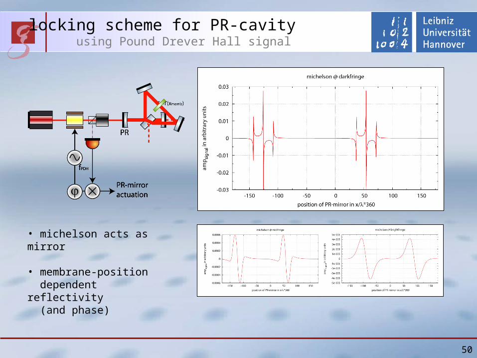
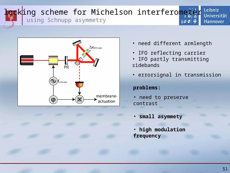
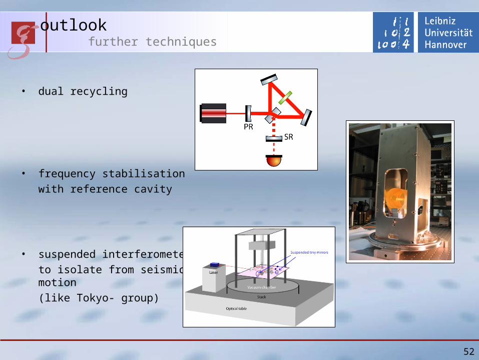
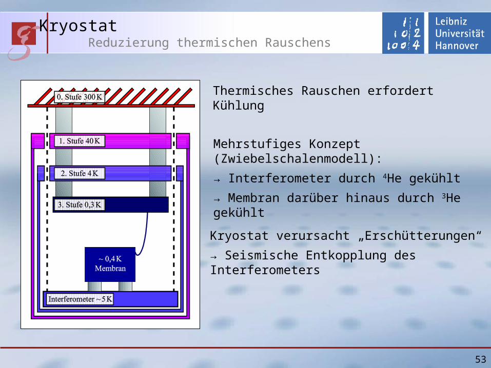
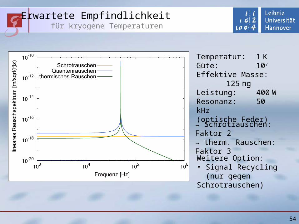
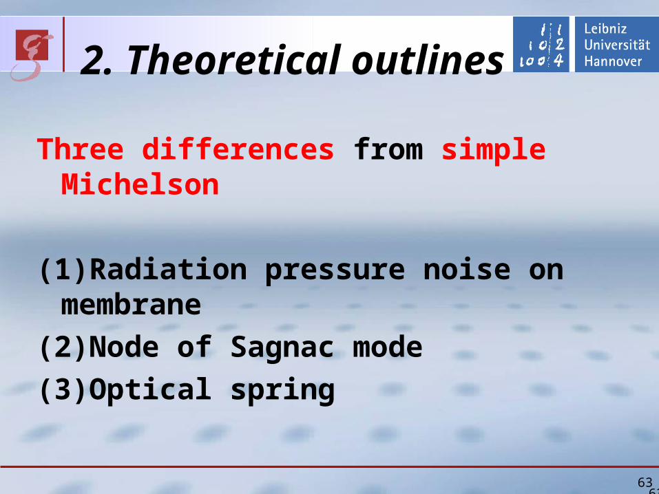
63
2 Theoretical outlines
Three differences from simple Michelson
(1)Radiation pressure noise on membrane
(2)Node of Sagnac mode
(3)Optical spring
63
2 Theoretical outlines Optical spring (1)
Optical spring (without cavity) Light acts as spring
Radiation pressure on membrane depends on its position
Radiation pressure changes
resonant frequency of membrane
6464
InterferenceInterference
Membrane
Shift
2 Theoretical outlines Optical spring (2)
Phase of Michelson mode Shift
Sign of shift on right side is opposite to that on left side
Phase of Sagnac mode No shift
6565
Left side of membrane
Sagnac
Michelson
Right side of membrane
Shift by membrane
Shift by membrane
Michelson
Sagnac
2 Theoretical outlines Optical spring (3)
Interference Constructive (larger power) on right side
Destructive (smaller power) on left side
Radiation pressure on right side becomes larger
(Optical spring effect)
6666
Sagnac
Michelson
Shift by membrane
Shift by membrane
Michelson
Sagnac
Left side of membrane Right side of membrane
2 Theoretical outlines Goal sensitivity
6767
Temperature 1 KQ 107
Effective Mass 125 ngPower at BS 400 WResonance 75 kHz(with optical spring)Resonance 50 kHz(without optical spring)
Shot noise Factor 2Thermal noise Factor 3
Option Signal Recycling 99 power reflectance Power at BS about 1W P
ow
er s
pec
tru
m d
ensi
ty [
mr
tHz]
Frequency[kHz]
Shot noiseQuantum noiseThermal noise
Without signal recycling
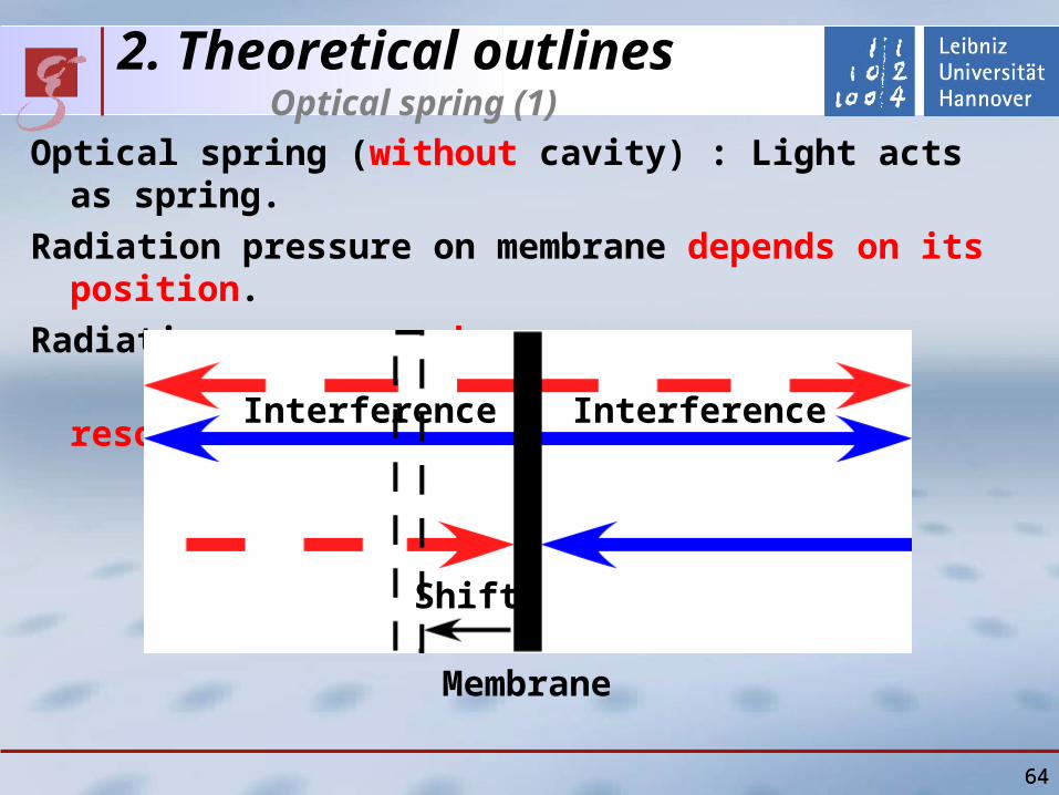
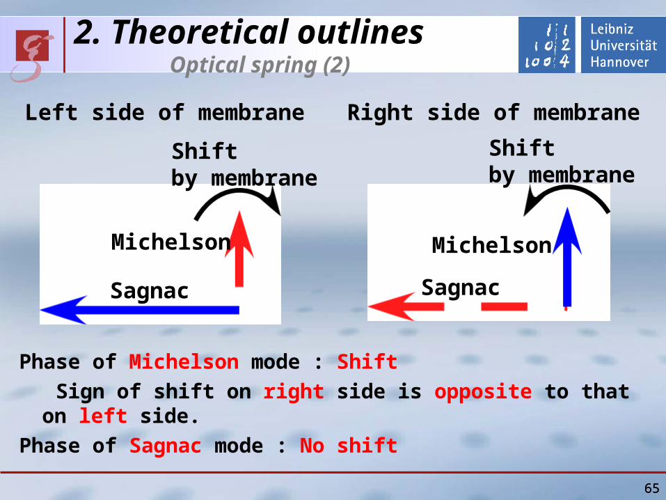
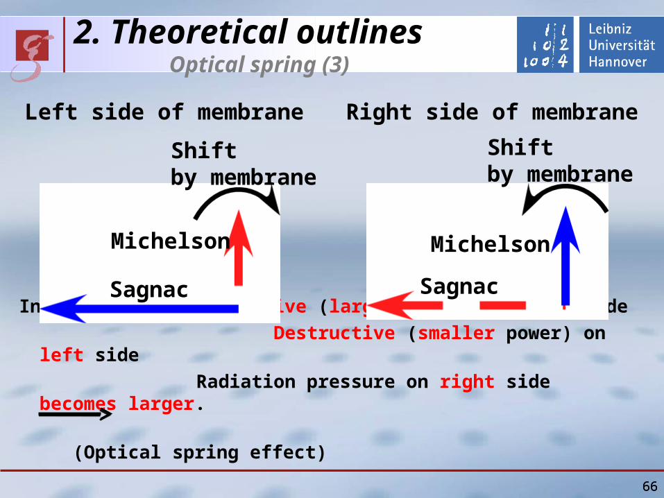
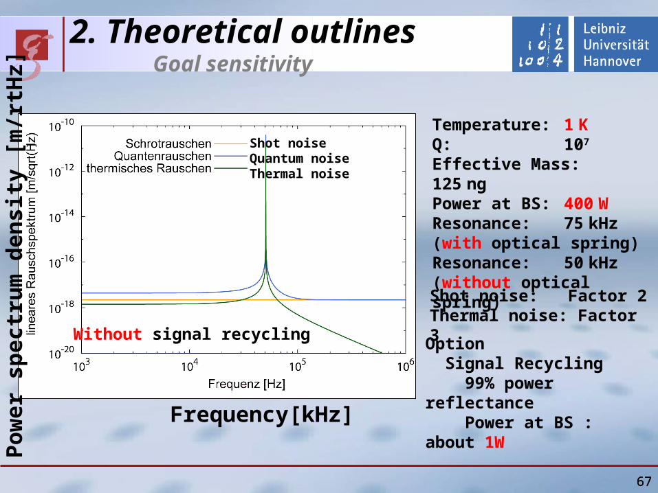