Embed Size (px)
Citation preview

Operating manual • English
Käyttöohje • Suomi
Bruksanvisning • Svenska
Bruksanvisning • Norsk
Brugsanvisning • Dansk
Gebrauchsanweisung • Deutsch
Gebruiksaanwijzing • Nederlands
Manuel d’utilisation • Français
Manual de instrucciones • Español
Instrukcja obsługi • Polski
Инструкции по эксплуатации • По-русски
操作手册 • 中文
Manual de utilização • Português
EN
FI
SV
NO
DA
DE
NL
FR
ES
PL
RU
ZH
KempArc™ Pulse 350, 450DT 400
PT


EN
Operating manualEnglish
Kem
parc
pul
se 3
50, 4
50 /
© K
empp
i Oy
/ 104
4
EN
ContEnts
1. IntroduCtIon ..................................................................................................................................31.1 general .................................................................................................................................................................31.2 about Kemparc pulse products ........................................................................................................3
2. InstAllAtIon ......................................................................................................................................42.1 Before use ..........................................................................................................................................................42.2 machine introduction ...............................................................................................................................42.3 positioning of the machine ...................................................................................................................52.4 Distribution network .................................................................................................................................52.5 Connecting cables .......................................................................................................................................6
3. opErAtIon Control ...............................................................................................................93.1 main switch i/O ..............................................................................................................................................93.2 pilot lamps .........................................................................................................................................................93.3 Operation of cooling fan .........................................................................................................................9
4. usIng thE mAChInE ................................................................................................................104.1 setup panel K 60 – layout ....................................................................................................................104.2 Setup panel K 60 ........................................................................................................................................104.3 Welding parametres and functions .............................................................................................124.4 KF 62 panel overview .............................................................................................................................19
5. KF 62 pAnEl Button FunCtIons ........................................................................205.1 On / OFF Button .........................................................................................................................................205.2 Dynamics Button .......................................................................................................................................215.3 gas test Button ...........................................................................................................................................215.4 Wire inch Button ........................................................................................................................................215.5 Channel -..........................................................................................................................................................215.6 Channel + ........................................................................................................................................................215.7 Save Button ....................................................................................................................................................225.8 extra functions Button ...........................................................................................................................225.9 Control display ............................................................................................................................................225.10 power encoder potentiometer ........................................................................................................225.11 arc length/voltage/adjustment potentiometer .................................................................225.12 getting started ............................................................................................................................................23
6. BAsIC trouBlEshootIng ..............................................................................................25
7. opErAtIon dIsturBAnCEs ..........................................................................................267.1 Operation of the overload protection........................................................................................267.2 Control fuses .................................................................................................................................................267.3 under and over voltages in the mains supply .....................................................................267.4 loss of a phase in the mains supply ...........................................................................................26
8. mAIntEnAnCE ..................................................................................................................................268.1 Daily maintenance ....................................................................................................................................268.2 period maintenance ................................................................................................................................278.3 Service shop maintenance .................................................................................................................27
9. dIsposAl oF thE mAChInE ..........................................................................................27
10. ordErIng numBErs ...............................................................................................................28
11. tEChnICAl dAtA ...........................................................................................................................29
2
Kem
parc
pul
se 3
50, 4
50 /
© K
empp
i Oy
/ 104
4

EN
1. IntroduCtIon
1.1 gEnErAlCongratulations on choosing the Kemparc™ pulse welding equipment. used correctly, Kemppi products can significantly increase the productivity of your welding, and provide years of economical service. this operating manual contains important information on the use, maintenance and safety of your Kemppi product. the technical specifications of the equipment can be found at the end of the manual. please read the manual carefully before using the equipment for the first time. For your own safety and that of your working environment, pay particular attention to the safety instructions in the manual.For more information on Kemppi products, contact Kemppi Oy, consult an authorised Kemppi dealer, or visit the Kemppi web site at www.kemppi.com.the specifications presented in this manual are subject to change without prior notice.
Important notesitems in the manual that require particular attention in order to minimise damage and personal harm are indicated with the ’NOTE!’ notation. read these sections carefully and follow their instructions.
1.2 ABout KEmpArC pulsE produCtsKemparc pulse 350 and 450 are CC/CV welding power sources designed for demanding professional use. they are suitable for synergic pulsed mig/mag, synergic 1-mig/mag and basic mig/mag. K 60 setup panel is included in the delivery for selecting, setting and managing the welding system prior to and during system use.Kemparc pulse 350/450 product range offers both technical and commercial welding solutions matching a wide range of applications from sheet metal fabrication to heavy industry segments.Kemparc Dt 400 is a wire feeding device that feeds welding wire to the welding robot at the speed it requires at any time. For more information on using the wire feeder and its functions, see “Wire feeder”.
3
Kem
parc
pul
se 3
50, 4
50 /
© K
empp
i Oy
/ 104
4
EN
2. InstAllAtIon
2.1 BEForE usEthe product is packed in specially designed transport cartons. However, before use always make sure the products have not been damaged during transportation.product packaging material is recyclable.
NOTE! When moving the welding machine, always lift it from the handle, never pull it from the welding gun or other cables.
operating environmentthis machine is suitable for both indoor and outdoor use. always make sure that the air flow to the machine is unrestricted. the recommended operating temperature range is -20…+40°C.please ensure you read the safety instructions concerning operating environments supplied in this manual.
2.2 mAChInE IntroduCtIon
6,3A
1.
2. 3.
4.8.
10.
11. 12. 13. 14.
5.
7.
9.6.
4
Kem
parc
pul
se 3
50, 4
50 /
© K
empp
i Oy
/ 104
4
EN
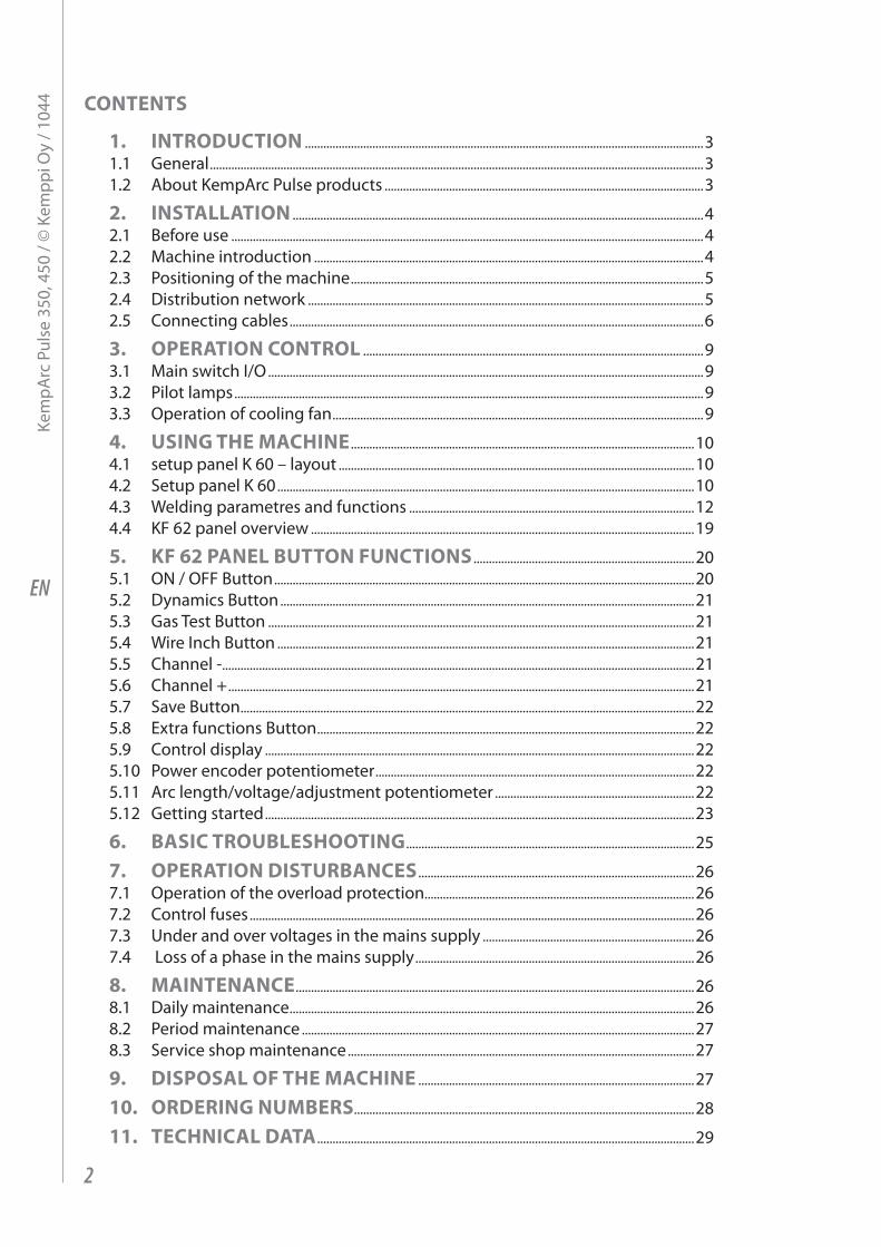
1. Setup panel K 602. main switch i/O - On/Off3. Signal lamp i/O - On/Off4. Warning lamp for thermal protection5. Welding cable connection - negative pole6. Welding cable connection + positive pole7. Control cable connection8. Fuse – 6.3 a delayed9. Control cable connection10. mains power cable11. robot control connection12. Wire feeder connection13. through put connection14. analog connection
2.3 posItIonIng oF thE mAChInEplace the machine on a firm, dry and level surface. Where possible, do not allow dust or other impurities to enter the machines cooling air flow. preferably site the machine above floor level; for example on a suitable carriage unit.notes for positioning the machine
• the surface inclination should not exceed 15 degrees.• ensure the free circulation of the cooling air. there must be at least 20 cm of free space in
front of and behind the machine for cooling air to circulate.• protect the machine against heavy rain and direct sunshine.
Note! the machine should not be operated in the rain as the protection class of the machine, IP23S, allows for outside preserving and storage only.
NOTE! Never aim metallic grinding spray/sparks towards the equipment.
2.4 dIstrIButIon nEtworKall regular electrical devices without special circuits generate harmonic currents into distribution network. High rates of harmonic current may cause losses and disturbance to some equipment.KempArc pulse 350 and 450:this equipment complies with ieC 61000-3-12 provided that the short-circuit power Ssc is greater than or equal to 5.5 mVa at the interface point between the user’s supply and the public suply network. it is the responsibility of the installer or user of the equipment to ensure, by consultation with the distribution network operator if necessary, that the equipment is connected only to a supply with a short-circuit power Ssc greater than or equal to 5.5 mVa.
5
Kem
parc
pul
se 3
50, 4
50 /
© K
empp
i Oy
/ 104
4
EN
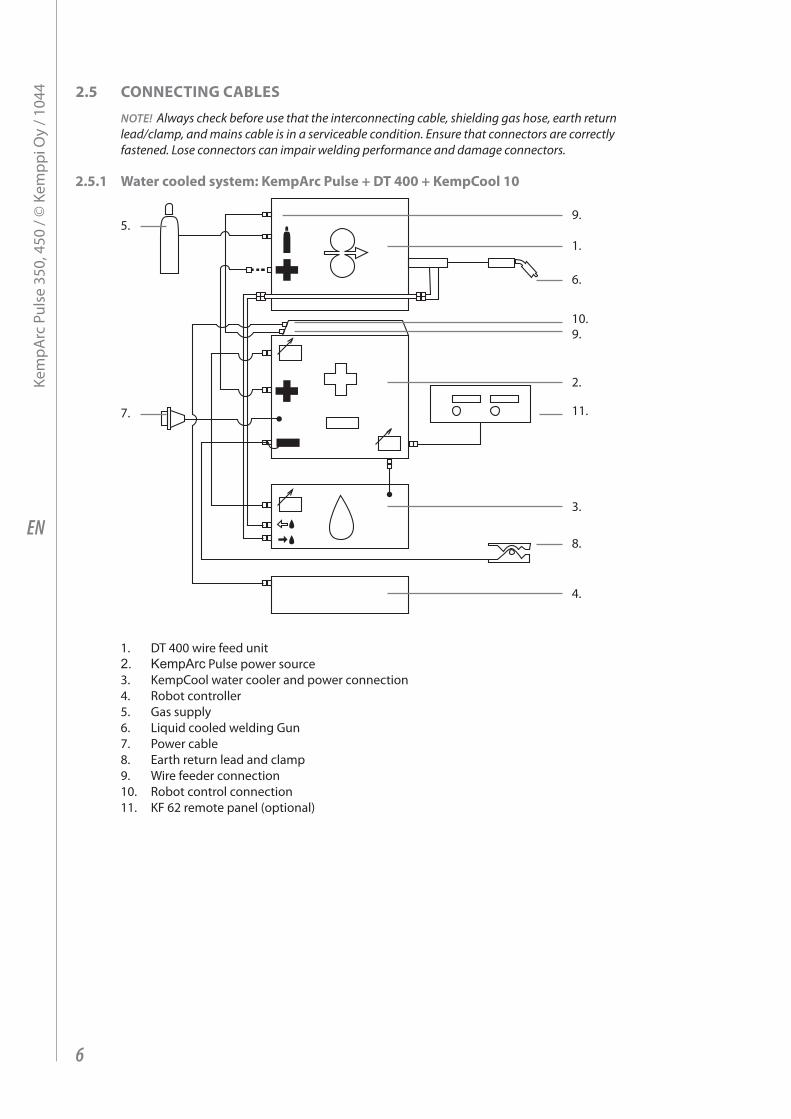
2.5 ConnECtIng CABlEs
NOTE! Always check before use that the interconnecting cable, shielding gas hose, earth return lead/clamp, and mains cable is in a serviceable condition. ensure that connectors are correctly fastened. Lose connectors can impair welding performance and damage connectors.
2.5.1 water cooled system: KempArc pulse + dt 400 + KempCool 10
1.
9.
9.10.
11.
5.
7.
2.
3.
4.
8.
6.
1. Dt 400 wire feed unit2. KempArc pulse power source3. KempCool water cooler and power connection4. robot controller5. gas supply6. liquid cooled welding gun7. power cable8. earth return lead and clamp9. Wire feeder connection10. robot control connection11. KF 62 remote panel (optional)
6
Kem
parc
pul
se 3
50, 4
50 /
© K
empp
i Oy
/ 104
4
EN
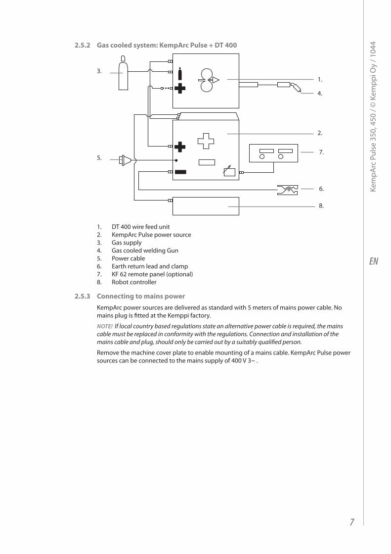
2.5.2 gas cooled system: KempArc pulse + dt 400
1.
4.
6.
7.
2.
8.
3.
5.
1. Dt 400 wire feed unit2. Kemparc pulse power source3. gas supply4. gas cooled welding gun5. power cable6. earth return lead and clamp7. KF 62 remote panel (optional)8. robot controller
2.5.3 Connecting to mains powerKemparc power sources are delivered as standard with 5 meters of mains power cable. no mains plug is fitted at the Kemppi factory.
NOTE! If local country based regulations state an alternative power cable is required, the mains cable must be replaced in conformity with the regulations. Connection and installation of the mains cable and plug, should only be carried out by a suitably qualified person.
remove the machine cover plate to enable mounting of a mains cable. Kemparc pulse power sources can be connected to the mains supply of 400 V 3~ .
7
Kem
parc
pul
se 3
50, 4
50 /
© K
empp
i Oy
/ 104
4
EN
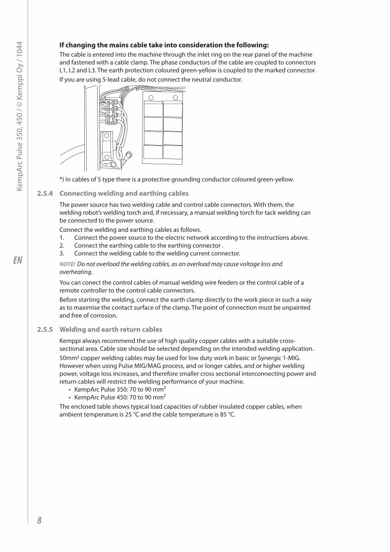
If changing the mains cable take into consideration the following:the cable is entered into the machine through the inlet ring on the rear panel of the machine and fastened with a cable clamp. the phase conductors of the cable are coupled to connectors l1, l2 and l3. the earth protection coloured green-yellow is coupled to the marked connector.if you are using 5-lead cable, do not connect the neutral conductor.
*) in cables of S type there is a protective grounding conductor coloured green-yellow.
2.5.4 Connecting welding and earthing cablesthe power source has two welding cable and control cable connectors. With them, the welding robot’s welding torch and, if necessary, a manual welding torch for tack welding can be connected to the power source. Connect the welding and earthing cables as follows.1. Connect the power source to the electric network according to the instructions above.2. Connect the earthing cable to the earthing connector .3. Connect the welding cable to the welding current connector.
NOTE! Do not overload the welding cables, as an overload may cause voltage loss and overheating.
You can conect the control cables of manual welding wire feeders or the control cable of a remote controller to the control cable connectors.Before starting the welding, connect the earth clamp directly to the work piece in such a way as to maximise the contact surface of the clamp. the point of connection must be unpainted and free of corrosion.
2.5.5 welding and earth return cablesKemppi always recommend the use of high quality copper cables with a suitable cross-sectional area. Cable size should be selected depending on the intended welding application.50mm2 copper welding cables may be used for low duty work in basic or Synergic 1-mig. However when using pulse mig/mag process, and or longer cables, and or higher welding power, voltage loss increases, and therefore smaller cross sectional interconnecting power and return cables will restrict the welding performance of your machine.
• Kemparc pulse 350: 70 to 90 mm² • Kemparc pulse 450: 70 to 90 mm²
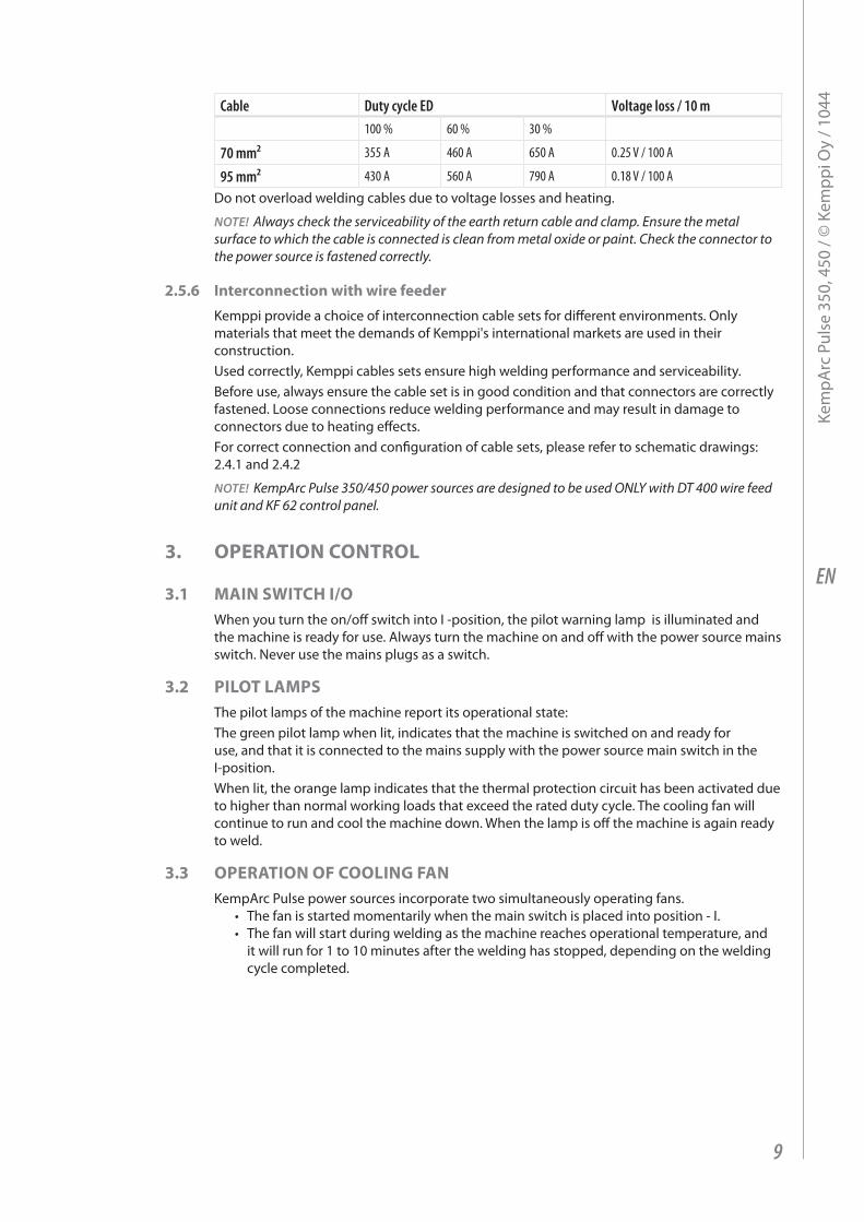
the enclosed table shows typical load capacities of rubber insulated copper cables, when ambient temperature is 25 °C and the cable temperature is 85 °C.
8
Kem
parc
pul
se 3
50, 4
50 /
© K
empp
i Oy
/ 104
4
EN
Cable Duty cycle ED Voltage loss / 10 m100 % 60 % 30 %
70 mm² 355 A 460 A 650 A 0.25 V / 100 A
95 mm² 430 A 560 A 790 A 0.18 V / 100 A
Do not overload welding cables due to voltage losses and heating.
NOTE! Always check the serviceability of the earth return cable and clamp. ensure the metal surface to which the cable is connected is clean from metal oxide or paint. Check the connector to the power source is fastened correctly.
2.5.6 Interconnection with wire feederKemppi provide a choice of interconnection cable sets for different environments. Only materials that meet the demands of Kemppi's international markets are used in their construction.used correctly, Kemppi cables sets ensure high welding performance and serviceability.Before use, always ensure the cable set is in good condition and that connectors are correctly fastened. loose connections reduce welding performance and may result in damage to connectors due to heating effects. For correct connection and configuration of cable sets, please refer to schematic drawings: 2.4.1 and 2.4.2
NOTE! KempArc Pulse 350/450 power sources are designed to be used oNLY with Dt 400 wire feed unit and KF 62 control panel.
3. opErAtIon Control
3.1 mAIn swItCh I/oWhen you turn the on/off switch into i -position, the pilot warning lamp is illuminated and the machine is ready for use. always turn the machine on and off with the power source mains switch. never use the mains plugs as a switch.
3.2 pIlot lAmpsthe pilot lamps of the machine report its operational state:the green pilot lamp when lit, indicates that the machine is switched on and ready for use, and that it is connected to the mains supply with the power source main switch in the i-position.When lit, the orange lamp indicates that the thermal protection circuit has been activated due to higher than normal working loads that exceed the rated duty cycle. the cooling fan will continue to run and cool the machine down. When the lamp is off the machine is again ready to weld.
3.3 opErAtIon oF CoolIng FAnKemparc pulse power sources incorporate two simultaneously operating fans.
• the fan is started momentarily when the main switch is placed into position - i.• the fan will start during welding as the machine reaches operational temperature, and
it will run for 1 to 10 minutes after the welding has stopped, depending on the welding cycle completed.
9
Kem
parc
pul
se 3
50, 4
50 /
© K
empp
i Oy
/ 104
4
EN
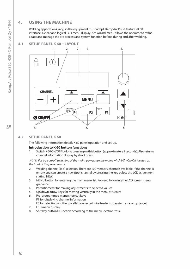
4. usIng thE mAChInEWelding applications vary, so the equipment must adapt. Kemparc pulse features K 60 interface, a clear and logical lCD menu display. arc Wizard menu allows the operator to refine, adapt and manage the arc process and system function before, during and after welding.
4.1 sEtup pAnEl K 60 – lAyout
CHANNEL
MENU
F1 F2 F3CHANNELINFO
WF #
1. 4.
5.6.
2. 7. 3.
8.
4.2 sEtup pAnEl K 60the following information details K 60 panel operation and set-up.
Introduction to K 60 button functions1. Switch K 60 On/OFF by long pressing on this button (approximately 5 seconds). also returns
channel information display by short press.
NOTE! For true on/off switching of the mains power, use the main switch I/o - on/off located on the front of the power source.2. Welding channel (job) selection. there are 100 memory channels available. if the channel is
empty you can create a new (job) channel by pressing the key below the lCD screen text stating neW.
3. menu button for entering the main menu list. proceed following the lCD screen menu guidance.
4. potentiometer for making adjustments to selected values5. up/down arrow keys for moving vertically in the menu structure6. pre-programmed menu shortcut keys
• F1 for displaying channel information • F3 for selecting another parallel connected wire feeder sub system as a setup target.
7. lCD menu display8. Soft key buttons. Function according to the menu location/task.
10
Kem
parc
pul
se 3
50, 4
50 /
© K
empp
i Oy
/ 104
4
EN
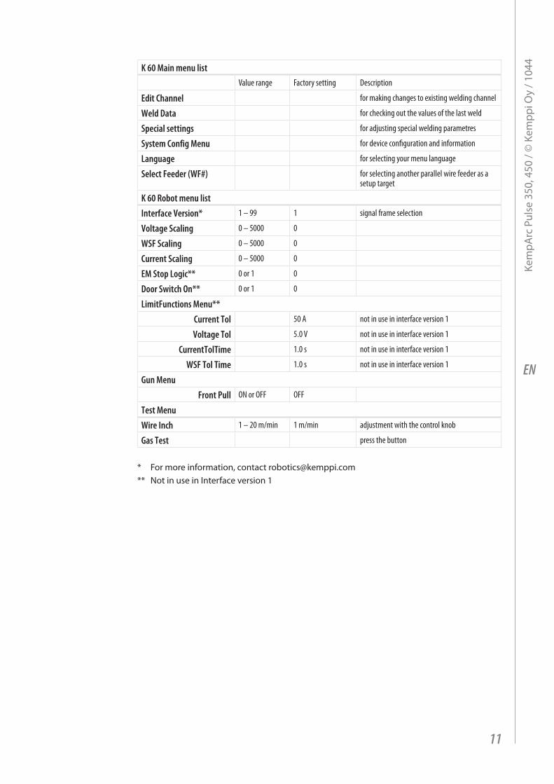
K 60 Main menu listValue range Factory setting Description
Edit Channel for making changes to existing welding channel
Weld Data for checking out the values of the last weld
Special settings for adjusting special welding parametres
System Config Menu for device configuration and information
Language for selecting your menu language
Select Feeder (WF#) for selecting another parallel wire feeder as a setup target
K 60 Robot menu listInterface Version* 1 – 99 1 signal frame selection
Voltage Scaling 0 – 5000 0
WSF Scaling 0 – 5000 0
Current Scaling 0 – 5000 0
EM Stop Logic** 0 or 1 0
Door Switch On** 0 or 1 0
LimitFunctions Menu**Current Tol 50 A not in use in interface version 1
Voltage Tol 5.0 V not in use in interface version 1
CurrentTolTime 1.0 s not in use in interface version 1
WSF Tol Time 1.0 s not in use in interface version 1
Gun MenuFront Pull ON or OFF OFF
Test MenuWire Inch 1 – 20 m/min 1 m/min adjustment with the control knob
Gas Test press the button
* For more information, contact [email protected]** not in use in interface version 1
11
Kem
parc
pul
se 3
50, 4
50 /
© K
empp
i Oy
/ 104
4
EN
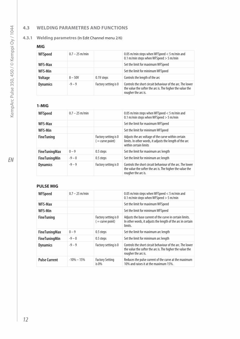
4.3 wEldIng pArAmEtrEs And FunCtIons
4.3.1 welding parametres (in edit Channel menu 2/6)
mIg
WFSpeed 0.7 – 25 m/min 0.05 m/min steps when WFSpeed < 5 m/min and 0.1 m/min steps when WFSpeed > 5 m/min
WFS-Max Set the limit for maximum WFSpeed
WFS-Min Set the limit for minimum WFSpeed
Voltage 8 – 50V 0.1V steps Controls the length of the arc
Dynamics -9 – 9 Factory setting is 0 Controls the short circuit behaviour of the arc. The lower the value the softer the arc is. The higher the value the rougher the arc is.
1-mIg
WFSpeed 0.7 – 25 m/min 0.05 m/min steps when WFSpeed < 5 m/min and 0.1 m/min steps when WFSpeed > 5 m/min
WFS-Max Set the limit for maximum WFSpeed
WFS-Min Set the limit for minimum WFSpeed
FineTuning Factory setting is 0 ( = curve point)
Adjusts the arc voltage of the curve within certain limits. In other words, it adjusts the length of the arc within certain limits
FineTuningMax 0 – 9 0.5 steps Set the limit for maximum arc length
FineTuningMin -9 – 0 0.5 steps Set the limit for minimum arc length
Dynamics -9 – 9 Factory setting is 0 Controls the short circuit behaviour of the arc. The lower the value the softer the arc is. The higher the value the rougher the arc is.
pulsE mIg
WFSpeed 0.7 – 25 m/min 0.05 m/min steps when WFSpeed < 5 m/min and 0.1 m/min steps when WFSpeed > 5 m/min
WFS-Max Set the limit for maximum WFSpeed
WFS-Min Set the limit for minimum WFSpeed
FineTuning Factory setting is 0 ( = curve point)
Adjusts the base current of the curve in certain limits. In other words, it adjusts the length of the arc in certain limits.
FineTuningMax 0 – 9 0.5 steps Set the limit for maximum arc length
FineTuningMin -9 – 0 0.5 steps Set the limit for minimum arc length
Dynamics -9 – 9 Factory setting is 0 Controls the short circuit behaviour of the arc. The lower the value the softer the arc is. The higher the value the rougher the arc is.
Pulse Current -10% – 15% Factory Setting is 0%
Reduces the pulse current of the curve at the maximum 10% and raises it at the maximum 15%.
12
Kem
parc
pul
se 3
50, 4
50 /
© K
empp
i Oy
/ 104
4
EN
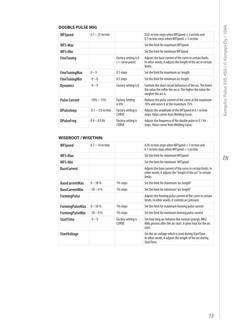
douBlE pulsE mIg
WFSpeed 0.7 – 25 m/min 0.05 m/min steps when WFSpeed < 5 m/min and 0.1 m/min steps when WFSpeed > 5 m/min
WFS-Max Set the limit for maximum WFSpeed
WFS-Min Set the limit for minimum WFSpeed
FineTuning Factory setting is 0 ( = curve point)
Adjusts the base current of the curve in certain limits. In other words, it adjusts the length of the arc in certain limits.
FineTuningMax 0 – 9 0.5 steps Set the limit for maximum arc length
FineTuningMin -9 – 0 0.5 steps Set the limit for minimum arc length
Dynamics -9 – 9 Factory setting is 0 Controls the short circuit behaviour of the arc. The lower the value the softer the arc is. The higher the value the rougher the arc is.
Pulse Current -10% – 15% Factory Setting is 0%
Reduces the pulse current of the curve at the maximum 10% and raises it at the maximum 15%
DPulseAmp 0.1 – 3.0 m/min Factory setting is CURVE
Adjusts the amplitude of the WFSpeed in 0.1 m/min steps. Value comes from Welding Curve.
DPulseFreq 0.4 – 8.0 Hz Factory setting is CURVE
Adjusts the frequency of the double pulse in 0.1 Hz steps. Value comes from Welding Curve.
wIsEroot / wIsEthIn)
WFSpeed 0.7 – 14 m/min 0.05 m/min steps when WFSpeed < 5 m/min and 0.1 m/min steps when WFSpeed > 5 m/min
WFS-Max Set the limit for maximum WFSpeed
WFS-Min Set the limit for minimum WFSpeed
BaseCurrent Adjusts the base current of the curve in certain limits. In other words, it adjusts the “length of the arc” in certain limits.
BaseCurrentMax 0 – 50 % 1% steps Set the limit for maximum “arc length”
BaseCurrentMin -50 – 0 % 1% steps Set the limit for minimum “arc length”
FormingPulse Adjusts the forming pulse current of the curve in certain limits. In other words, it controls arc pressure.
FormingPulseMax 0 – 50 % 1% steps Set the limit for maximum forming pulse current
FormingPulseMin -50 – 0 % 1% steps Set the limit for minimum forming pulse current
StartTime -9 – 9 Factory setting is CURVE
Set how long arc behaves like normal synergic MIG/MAG prosess after the arc start. It gives heat for the arc start.
StartVoltage Set the arc voltage which is used during StartTime. In other words, it adjusts the length of the arc during StartTime.
13
Kem
parc
pul
se 3
50, 4
50 /
© K
empp
i Oy
/ 104
4
EN
4.3.2 welding functions
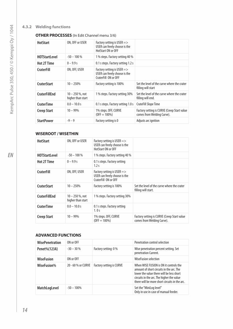
othEr proCEssEs (in edit Channel menu 3/6)
HotStart ON, OFF or USER Factory setting is USER => USER can freely choose is the HotStart ON or OFF
HOTStartLevel -50 – 100 % 1 % steps. Factory setting 40 %
Hot 2T Time 0 – 9.9 s 0.1 s steps. Factory setting 1.2 s
CraterFill ON, OFF, USER Factory setting is USER => USER can freely choose is the CraterFill ON or OFF
CraterStart 10 – 250% Factory setting is 100% Set the level of the curve where the crater filling will start
CraterFillEnd 10 – 250 %, not higher than start
1 % steps. Factory setting 30% Set the level of the curve where the crater filling will end.
CraterTime 0.0 – 10.0 s 0.1 s steps. Factory setting 1.0 s CrateFill Slope Time
Creep Start 10 – 99% 1% steps. OFF, CURVE (OFF = 100%)
Factory setting is CURVE (Creep Start value comes from Welding Curve).
StartPower -9 – 9 Factory setting is 0 Adjusts arc ignition
wIsEroot / wIsEthIn
HotStart ON, OFF or USER Factory setting is USER => USER can freely choose is the HotStart ON or OFF
HOTStartLevel -50 – 100 % 1 % steps. Factory setting 40 %
Hot 2T Time 0 – 9.9 s 0.1 s steps. Factory setting 1.2 s
CraterFill ON, OFF, USER Factory setting is USER => USER can freely choose is the CraterFill ON or OFF
CraterStart 10 – 250% Factory setting is 100% Set the level of the curve where the crater filling will start.
CraterFillEnd 10 – 250 %, not higher than start
1 % steps. Factory setting 30%
CraterTime 0.0 – 10.0 s 0.1 s steps. Factory setting 1. 0 s
Creep Start 10 – 99% 1% steps. OFF, CURVE (OFF = 100%)
Factory setting is CURVE (Creep Start value comes from Welding Curve).
AdVAnCEd FunCtIons
WisePenetration ON or OFF Penetration control selection
Penet%(123A) -30 – 30 % Factory setting: 0 % Wise penetration percent setting. Set penetration Current.
WiseFusion ON or OFF WiseFusion selection
WiseFusion% 20 - 60 % or CURVE Factory setting is CURVE When WISE FUSION is ON it controls the amount of short circuits in the arc. The lower the value there will be less short circuits in the arc. The higher the value there will be more short circuits in the arc.
MatchLogLevel -50 – 100% Set the “MiniLog level” Only in use in case of manual feeder.
14
Kem
parc
pul
se 3
50, 4
50 /
© K
empp
i Oy
/ 104
4
EN
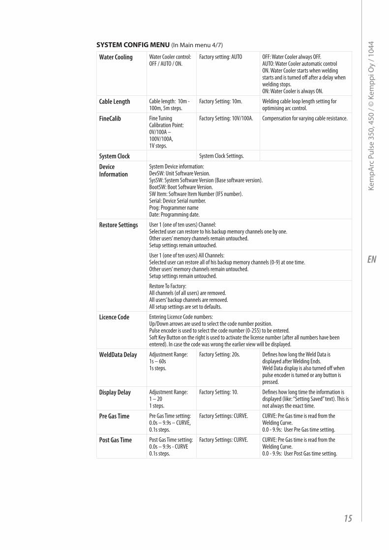
systEm ConFIg mEnu (in main menu 4/7)
Water Cooling Water Cooler control: OFF / AUTO / ON.
Factory setting: AUTO OFF: Water Cooler always OFF. AUTO: Water Cooler automatic control ON. Water Cooler starts when welding starts and is turned off after a delay when welding stops. ON: Water Cooler is always ON.
Cable Length Cable length: 10m - 100m, 5m steps.
Factory Setting: 10m. Welding cable loop length setting for optimising arc control.
FineCalib Fine Tuning Calibration Point: 0V/100A – 100V/100A, 1V steps.
Factory Setting: 10V/100A. Compensation for varying cable resistance.
System Clock System Clock Settings.
Device Information
System Device information: DevSW: Unit Software Version. SysSW: System Software Version (Base software version). BootSW: Boot Software Version. SW Item: Software Item Number (IFS number). Serial: Device Serial number. Prog: Programmer name Date: Programming date.
Restore Settings User 1 (one of ten users) Channel: Selected user can restore to his backup memory channels one by one. Other users’ memory channels remain untouched. Setup settings remain untouched.
User 1 (one of ten users) All Channels: Selected user can restore all of his backup memory channels (0-9) at one time. Other users’ memory channels remain untouched. Setup settings remain untouched.
Restore To Factory: All channels (of all users) are removed. All users’ backup channels are removed. All setup settings are set to defaults.
Licence Code Entering Licence Code numbers:Up/Down arrows are used to select the code number position. Pulse encoder is used to select the code number (0-255) to be entered. Soft Key Button on the right is used to activate the license number (after all numbers have been entered). In case the code was wrong the earlier view will be displayed.
WeldData Delay Adjustment Range: 1s – 60s 1s steps.
Factory Setting: 20s. Defines how long the Weld Data is displayed after Welding Ends. Weld Data display is also turned off when pulse encoder is turned or any button is pressed.
Display Delay Adjustment Range: 1 – 20 1 steps.
Factory Setting: 10. Defines how long time the information is displayed (like: “Setting Saved” text). This is not always the exact time.
Pre Gas Time Pre Gas Time setting: 0.0s – 9.9s – CURVE, 0.1s steps.
Factory Settings: CURVE. CURVE: Pre Gas time is read from the Welding Curve. 0.0 - 9.9s: User Pre Gas time setting.
Post Gas Time Post Gas Time setting: 0.0s – 9.9s - CURVE 0.1s steps.
Factory Settings: CURVE. CURVE: Pre Gas time is read from the Welding Curve. 0.0 - 9.9s: User Post Gas time setting.
15
Kem
parc
pul
se 3
50, 4
50 /
© K
empp
i Oy
/ 104
4
EN
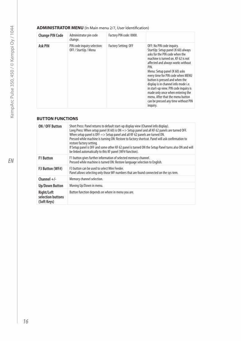
AdmInIstrAtor mEnu (in main menu 2/7, user identification)
Change PIN Code Administrator pin code change.
Factory PIN code: 0000.
Ask PIN PIN code inquiry selection: OFF / StartUp / Menu
Factory Setting: OFF OFF: No PIN code inquiry. StartUp: Setup panel (K 60) always asks for the PIN code when the machine is turned on. KF 62 is not affected and always works without PIN. Menu: Setup panel (K 60) asks every time for PIN code when MENU button is pressed and when the display is in channel info mode i.e. in start-up view. PIN code inquiry is made only once when entering the menu. After that the menu button can be pressed any time without PIN inquiry.
Button FunCtIons
ON / OFF Button Short Press: Panel returns to default start-up display view (Channel info display). Long Press: When setup panel (K 60) is ON => Setup panel and all KF 62 panels are turned OFF. When setup panel is OFF => Setup panel and all KF 62 panels are turned ON. Pressed while machine is turning ON: Restore to factory shortcut. Panel will ask confirmation to restore factory setting. If Setup panel is OFF and some other KF 62 panel is turned ON the Setup Panel turns also ON and will be linked automatically to this KF panel (WF# function).
F1 Button F1 button gives further information of selected memory channel. Pressed while machine is turned ON: Restore language selection to English.
F3 Button (WF#) F3 button can be used to select Wire Feeder. Panel allows selecting only those WF numbers that are found connected on the sys-tem.
Channel +/- Memory channel selection.
Up/Down Button Moving Up/Down in menu.
Right/Left selection buttons (Soft Keys)
Button function depends on where in menu you are.
16
Kem
parc
pul
se 3
50, 4
50 /
© K
empp
i Oy
/ 104
4
EN
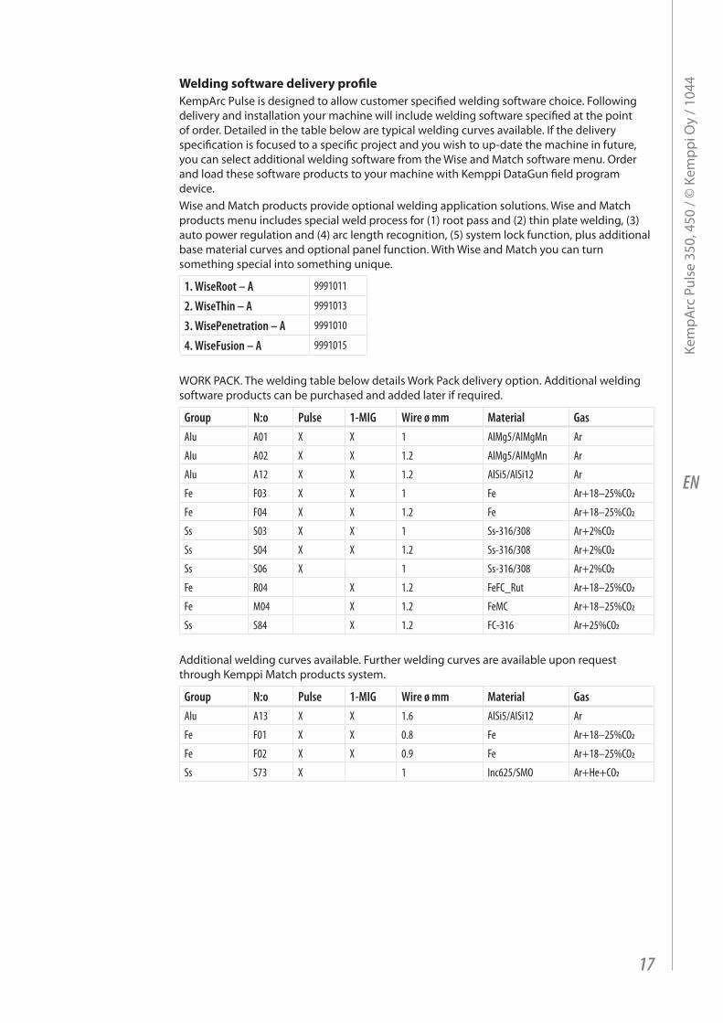
welding software delivery profileKemparc pulse is designed to allow customer specified welding software choice. Following delivery and installation your machine will include welding software specified at the point of order. Detailed in the table below are typical welding curves available. if the delivery specification is focused to a specific project and you wish to up-date the machine in future, you can select additional welding software from the Wise and match software menu. Order and load these software products to your machine with Kemppi Datagun field program device. Wise and match products provide optional welding application solutions. Wise and match products menu includes special weld process for (1) root pass and (2) thin plate welding, (3) auto power regulation and (4) arc length recognition, (5) system lock function, plus additional base material curves and optional panel function. With Wise and match you can turn something special into something unique.
1. WiseRoot – A 9991011
2. WiseThin – A 9991013
3. WisePenetration – A 9991010
4. WiseFusion – A 9991015
WOrK paCK. the welding table below details Work pack delivery option. additional welding software products can be purchased and added later if required.
Group N:o Pulse 1-MIG Wire ø mm Material GasAlu A01 X X 1 AlMg5/AlMgMn Ar
Alu A02 X X 1.2 AlMg5/AlMgMn Ar
Alu A12 X X 1.2 AlSi5/AlSi12 Ar
Fe F03 X X 1 Fe Ar+18–25%CO2
Fe F04 X X 1.2 Fe Ar+18–25%CO2
Ss S03 X X 1 Ss-316/308 Ar+2%CO2
Ss S04 X X 1.2 Ss-316/308 Ar+2%CO2
Ss S06 X 1 Ss-316/308 Ar+2%CO2
Fe R04 X 1.2 FeFC_Rut Ar+18–25%CO2
Fe M04 X 1.2 FeMC Ar+18–25%CO2
Ss S84 X 1.2 FC-316 Ar+25%CO2
additional welding curves available. Further welding curves are available upon request through Kemppi match products system.
Group N:o Pulse 1-MIG Wire ø mm Material GasAlu A13 X X 1.6 AlSi5/AlSi12 Ar
Fe F01 X X 0.8 Fe Ar+18–25%CO2
Fe F02 X X 0.9 Fe Ar+18–25%CO2
Ss S73 X 1 Inc625/SMO Ar+He+CO2
17
Kem
parc
pul
se 3
50, 4
50 /
© K
empp
i Oy
/ 104
4
EN
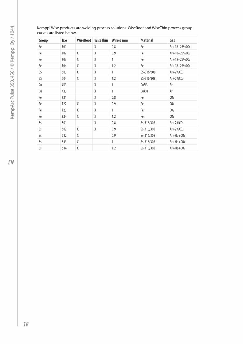
Kemppi Wise products are welding process solutions. Wiseroot and Wisethin process group curves are listed below.
Group N:o WiseRoot WiseThin Wire ø mm Material GasFe F01 X 0.8 Fe Ar+18–25%CO2
Fe F02 X X 0.9 Fe Ar+18–25%CO2
Fe F03 X X 1 Fe Ar+18–25%CO2
Fe F04 X X 1.2 Fe Ar+18–25%CO2
SS S03 X X 1 SS-316/308 Ar+2%CO2
SS S04 X X 1.2 SS-316/308 Ar+2%CO2
Cu C03 X 1 CuSi3 Ar
Cu C13 X 1 CuAl8 Ar
Fe F21 X 0.8 Fe CO2
Fe F22 X X 0.9 Fe CO2
Fe F23 X X 1 Fe CO2
Fe F24 X X 1.2 Fe CO2
Ss S01 X 0.8 Ss-316/308 Ar+2%CO2
Ss S02 X X 0.9 Ss-316/308 Ar+2%CO2
Ss S12 X 0.9 Ss-316/308 Ar+He+CO2
Ss S13 X 1 Ss-316/308 Ar+He+CO2
Ss S14 X 1.2 Ss-316/308 Ar+He+CO2
18
Kem
parc
pul
se 3
50, 4
50 /
© K
empp
i Oy
/ 104
4
EN
4.4 KF 62 pAnEl oVErVIEw
POWER
WISE
PULSECHANNEL1-MIG
SAVE
ROBOT
PANEL
CONTROLMIG
DOUBLEPULSE
U
A s
Vm/minmm
KF 62
W00
4330
+ / –
12. 13.11.9. 7.
1. 4.3. 5.2. 6.
8. 10.
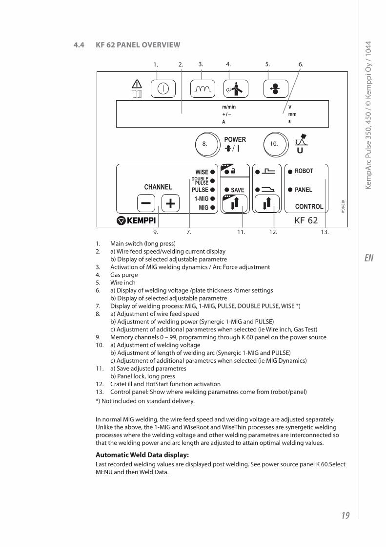
1. main switch (long press)2. a) Wire feed speed/welding current display
b) Display of selected adjustable parametre3. activation of mig welding dynamics / arc Force adjustment4. gas purge 5. Wire inch 6. a) Display of welding voltage /plate thickness /timer settings
b) Display of selected adjustable parametre7. Display of welding process: mig, 1-mig, pulSe, DOuBle pulSe, WiSe *)8. a) adjustment of wire feed speed
b) adjustment of welding power (Synergic 1-mig and pulSe) c) adjustment of additional parametres when selected (ie Wire inch, gas test)
9. memory channels 0 – 99, programming through K 60 panel on the power source 10. a) adjustment of welding voltage
b) adjustment of length of welding arc (Synergic 1-mig and pulSe) c) adjustment of additional parametres when selected (ie mig Dynamics)
11. a) Save adjusted parametres b) panel lock, long press
12. CrateFill and HotStart function activation13. Control panel: Show where welding parametres come from (robot/panel)*) not included on standard delivery.
in normal mig welding, the wire feed speed and welding voltage are adjusted separately. unlike the above, the 1-mig and Wiseroot and Wisethin processes are synergetic welding processes where the welding voltage and other welding parametres are interconnected so that the welding power and arc length are adjusted to attain optimal welding values.
Automatic weld data display:last recorded welding values are displayed post welding. See power source panel K 60.Select menu and then Weld Data.
19
Kem
parc
pul
se 3
50, 4
50 /
© K
empp
i Oy
/ 104
4
EN
5. KF 62 pAnEl Button FunCtIons
POWER
WISE
PULSECHANNEL1-MIG
SAVE
ROBOT
PANEL
CONTROLMIG
DOUBLEPULSE
U
A s
Vm/minmm
KF 62
W00
4330
+ / –
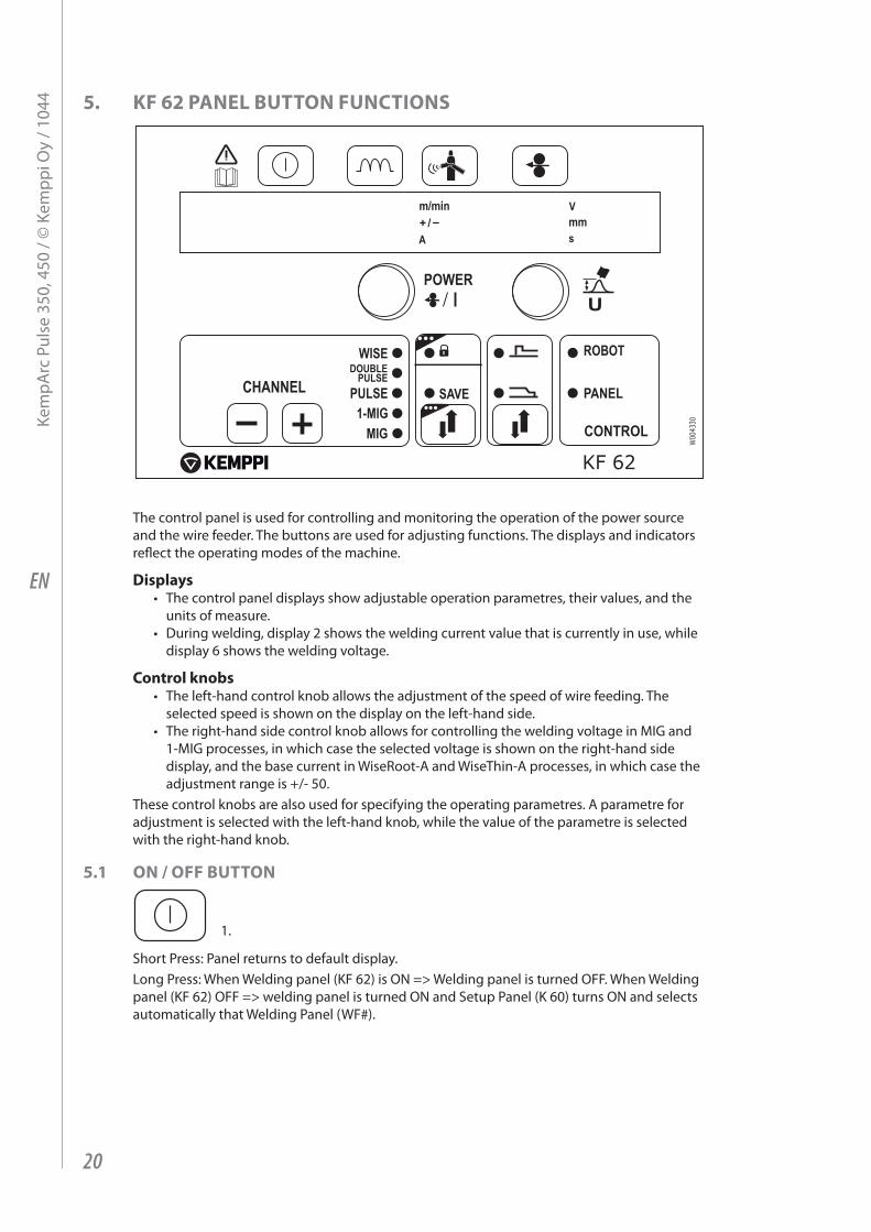
the control panel is used for controlling and monitoring the operation of the power source and the wire feeder. the buttons are used for adjusting functions. the displays and indicators reflect the operating modes of the machine.
displays• the control panel displays show adjustable operation parametres, their values, and the
units of measure.• During welding, display 2 shows the welding current value that is currently in use, while
display 6 shows the welding voltage.
Control knobs• the left-hand control knob allows the adjustment of the speed of wire feeding. the
selected speed is shown on the display on the left-hand side.• the right-hand side control knob allows for controlling the welding voltage in mig and
1-mig processes, in which case the selected voltage is shown on the right-hand side display, and the base current in Wiseroot-a and Wisethin-a processes, in which case the adjustment range is +/- 50.
these control knobs are also used for specifying the operating parametres. a parametre for adjustment is selected with the left-hand knob, while the value of the parametre is selected with the right-hand knob.
5.1 on / oFF Button
1.
Short press: panel returns to default display.long press: When Welding panel (KF 62) is On => Welding panel is turned OFF. When Welding panel (KF 62) OFF => welding panel is turned On and Setup panel (K 60) turns On and selects automatically that Welding panel (WF#).
20
Kem
parc
pul
se 3
50, 4
50 /
© K
empp
i Oy
/ 104
4
EN
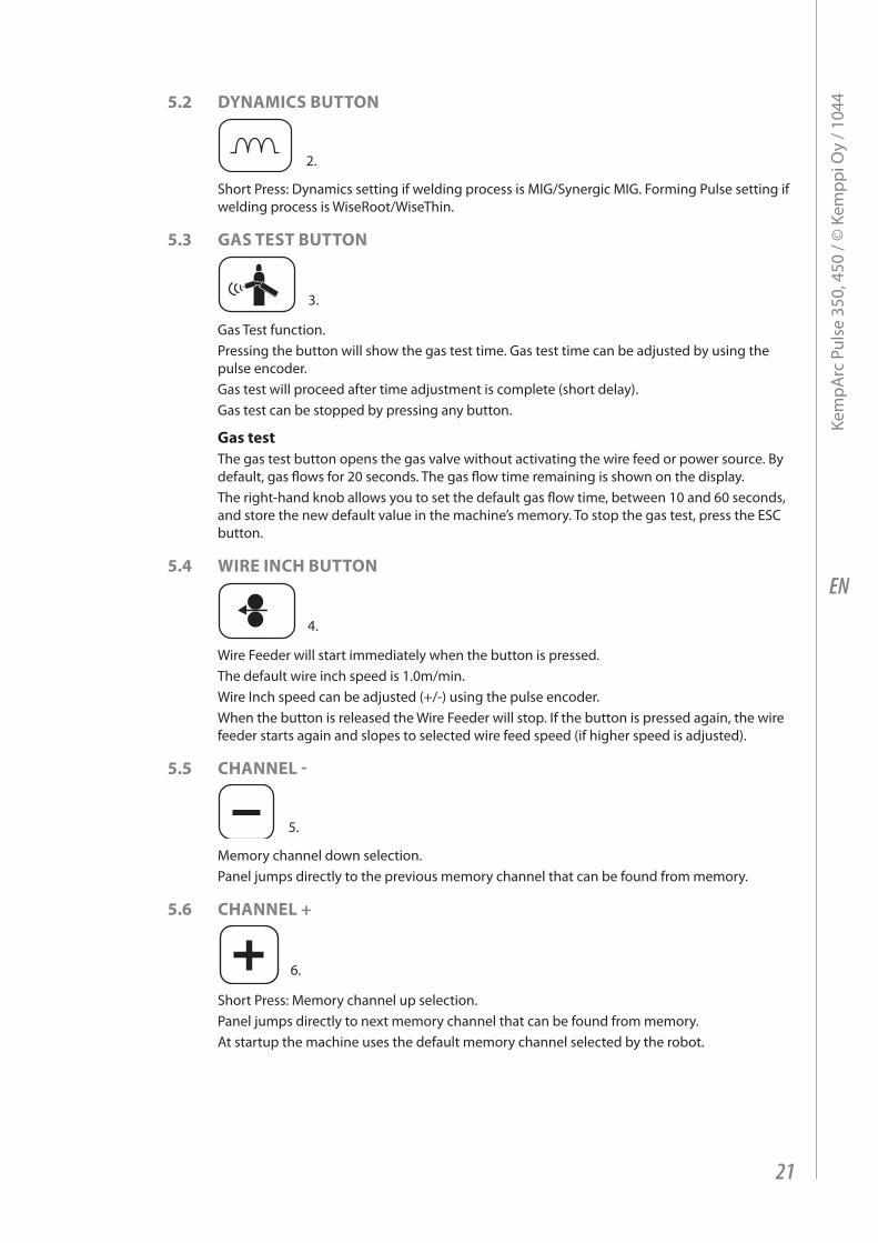
5.2 dynAmICs Button
2.
Short press: Dynamics setting if welding process is mig/Synergic mig. Forming pulse setting if welding process is Wiseroot/Wisethin.
5.3 gAs tEst Button
3.
gas test function.pressing the button will show the gas test time. gas test time can be adjusted by using the pulse encoder.gas test will proceed after time adjustment is complete (short delay).gas test can be stopped by pressing any button.
gas testthe gas test button opens the gas valve without activating the wire feed or power source. By default, gas flows for 20 seconds. the gas flow time remaining is shown on the display.the right-hand knob allows you to set the default gas flow time, between 10 and 60 seconds, and store the new default value in the machine’s memory. to stop the gas test, press the eSC button.
5.4 wIrE InCh Button
4.
Wire Feeder will start immediately when the button is pressed.the default wire inch speed is 1.0m/min.Wire inch speed can be adjusted (+/-) using the pulse encoder.When the button is released the Wire Feeder will stop. if the button is pressed again, the wire feeder starts again and slopes to selected wire feed speed (if higher speed is adjusted).
5.5 ChAnnEl -
5.
memory channel down selection.panel jumps directly to the previous memory channel that can be found from memory.
5.6 ChAnnEl +
6.
Short press: memory channel up selection.panel jumps directly to next memory channel that can be found from memory.at startup the machine uses the default memory channel selected by the robot.
21
Kem
parc
pul
se 3
50, 4
50 /
© K
empp
i Oy
/ 104
4
EN
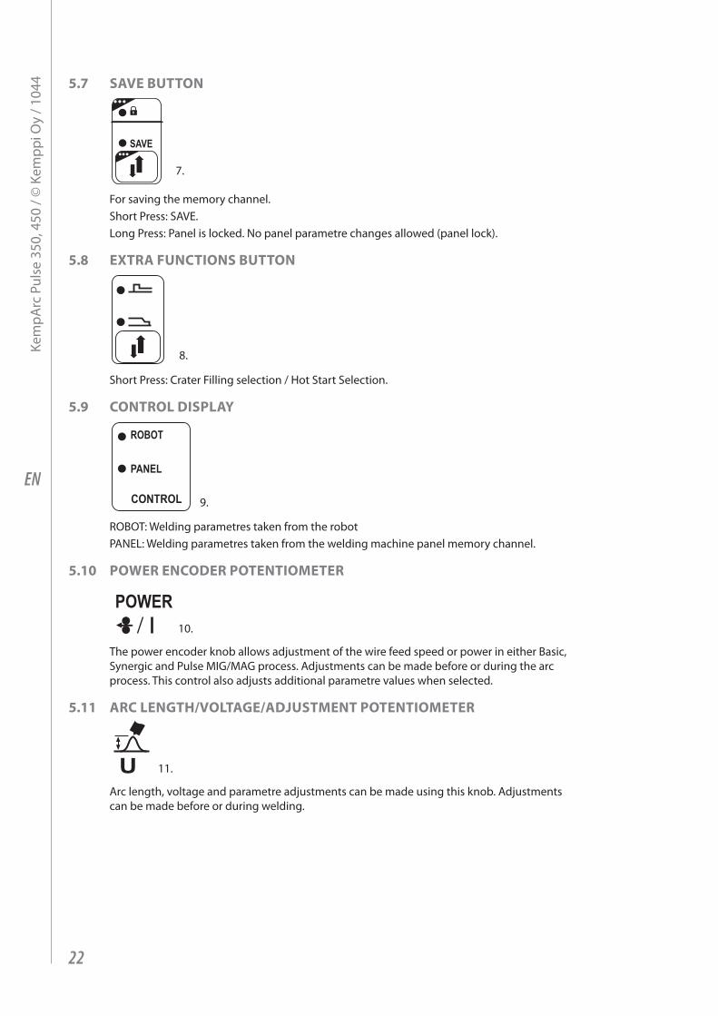
5.7 sAVE Button
SAVE
7.
For saving the memory channel.Short press: SaVe.long press: panel is locked. no panel parametre changes allowed (panel lock).
5.8 ExtrA FunCtIons Button
8.
Short press: Crater Filling selection / Hot Start Selection.
5.9 Control dIsplAy
ROBOT
PANEL
CONTROL 9.
rOBOt: Welding parametres taken from the robotpanel: Welding parametres taken from the welding machine panel memory channel.
5.10 powEr EnCodEr potEntIomEtEr
POWER10.
the power encoder knob allows adjustment of the wire feed speed or power in either Basic, Synergic and pulse mig/mag process. adjustments can be made before or during the arc process. this control also adjusts additional parametre values when selected.
5.11 ArC lEngth/VoltAgE/AdjustmEnt potEntIomEtEr
U 11.
arc length, voltage and parametre adjustments can be made using this knob. adjustments can be made before or during welding.
22
Kem
parc
pul
se 3
50, 4
50 /
© K
empp
i Oy
/ 104
4

EN
5.12 gEttIng stArtEdstep by step for the first time user
First select your language
NOTE! the default menu language is english. In the following steps you will be able to select alternative languages 1. Connect mains power and switch on power source. if this is the initial system activation you
may need to press and hold the large orange On/OFF button on K 60 panel. top left - long press (approximately 5 seconds).
2. now press button marked ‘menu’ to display main menu listing. there are 8 x items in this main menu list. as you select each item in the list, the reference number (Bottom middle display) will change e.g. 2/7 or 5/7 etc, showing which menu item you have selected. (You can cycle from first to last or last to first in a loop in all menu lists, if you wish). a black arrow marks your menu item selected.
3. menu items are selected via the up-DOWn buttons marked with orange arrows. these buttons are situated underneath the encoder knob to the right of the panel. move the ‘black arrow cursor’ up and down the menu lists. press down arrow button selecting item 5/7 marked language. press soft key button underneath the word SeleCt.
4. make your language choice as detailed above, and then press the SeleCt/SaVe button (right-hand button next to menu button). Your language choice is now confirmed and will remain selected unless you change it later.
new channel job numberKemparc pulse is designed for production jobs as well as varied specialist operation. main welding set-up is made through the K 60 menu and recorded to a ‘Channel (Job) number’ of your choice. When you want to weld you simply select the corresponding channel (Job) number on the wire feeder control panel KF 62 and start welding. Only the most often used controls are available in the KF 62 control panel, making welding easy and convenient.
NOTE! If the machine is new and no welding has been completed before, follow these steps.
a. Switch on power source (may require long press of panel On/OFF button - 5 sec). 1. press and select neW button. 2. Create new Channel – press SeleCt button. 3. Choose weld process and press SeleCt button. B. then follow the steps from item 4 in the list below.
Editing an existing channel (job) number1. press button marked ‘menu’ to show main menu listing. 2. SeleCt ‘edit Channel’ - press SeleCt button3. SeleCt ‘Select Weld Curve’ - press SeleCt button4. Choose and SeleCt process. mig/1-mig/pulse mig/Double pulse mig/ or Curve number list -
press SeleCt button5. Choose and SeleCt material group - press SeleCt button6. Choose and SeleCt material grade - press SeleCt button7. Choose and SeleCt filler wire diameter - press SeleCt button8. Choose and SeleCt shielding gas - press SeleCt button9. Choose and SeleCt curve - press SeleCt button. (note: the curve(s) presented in this view are
based on your previous selections from items 4 through to 8.)10. Choose and SaVe memory channel number. memory channel selections are made using
either the White +/- buttons Or Orange up-DOWn buttons - press SaVe button
23
Kem
parc
pul
se 3
50, 4
50 /
© K
empp
i Oy
/ 104
4

EN
reaDY tO WelD: Your basic welding selection and set-up is now complete. You are ready to weld, providing you select the corresponding channel ‘Job’ number on the KF 62 remote control panel. Set your welding power and arc length and weld.
NOTE! If you SeLeCt ‘MIG’ (i.e. Basic MIG/MAG selection in the above listing) you will automatically jump from item 4 to item 9. When you have saved your channel ‘Job’ number selection, you will have access to basic MIG/MAG welding on this channel. Voltage and wire feed speed are then selected in the normal way.
memory ‘job’ ChannelsSo there is a maximum of 100 x channels available for a variety of welding ‘Job’s or welding projects.Welding parametres can be quickly saved to memOrY ‘Job’ CHannel numbers and recalled later or updated later unless ‘locked’ via the four digits aDminiStratOr pin code lock.
K 60 – Fast Function Keysthe fast function keys, F1 and F3 are short cut keys.
• F1 CHannel inFO – Display the basic data recorded to the displayed channel.• F3 WF# – Displays active and selected wire feed unit and allows a new WFu selection.
Kemparc pulse allows up to 7 x wire feed units to be connected to one power source.
NOTE! only one wire feed unit can be active at any one time and must be selected before it will operate.
24
Kem
parc
pul
se 3
50, 4
50 /
© K
empp
i Oy
/ 104
4
EN
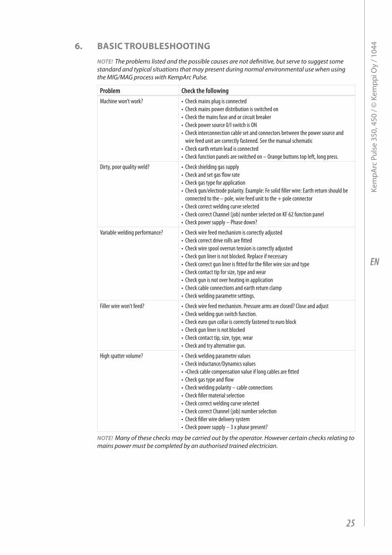
6. BAsIC trouBlEshootIng
NOTE! the problems listed and the possible causes are not definitive, but serve to suggest some standard and typical situations that may present during normal environmental use when using the MIG/MAG process with KempArc Pulse.
Problem Check the followingMachine won’t work? • Check mains plug is connected
• Check mains power distribution is switched on• Check the mains fuse and or circuit breaker• Check power source 0/I switch is ON• Check interconnection cable set and connectors between the power source and
wire feed unit are correctly fastened. See the manual schematic• Check earth return lead is connected• Check function panels are switched on – Orange buttons top left, long press.
Dirty, poor quality weld? • Check shielding gas supply• Check and set gas flow rate• Check gas type for application• Check gun/electrode polarity. Example: Fe solid filler wire: Earth return should be
connected to the – pole, wire feed unit to the + pole connector • Check correct welding curve selected• Check correct Channel (job) number selected on KF 62 function panel • Check power supply – Phase down?
Variable welding performance? • Check wire feed mechanism is correctly adjusted• Check correct drive rolls are fitted• Check wire spool overrun tension is correctly adjusted• Check gun liner is not blocked. Replace if necessary• Check correct gun liner is fitted for the filler wire size and type• Check contact tip for size, type and wear• Check gun is not over heating in application • Check cable connections and earth return clamp• Check welding parametre settings.
Filler wire won’t feed? • Check wire feed mechanism. Pressure arms are closed? Close and adjust• Check welding gun switch function.• Check euro gun collar is correctly fastened to euro block• Check gun liner is not blocked• Check contact tip, size, type, wear• Check and try alternative gun.
High spatter volume? • Check welding parametre values• Check inductance/Dynamics values• •Checkcablecompensationvalueiflongcablesarefitted• Check gas type and flow• Check welding polarity – cable connections• Check filler material selection• Check correct welding curve selected• Check correct Channel (job) number selection • Check filler wire delivery system• Check power supply – 3 x phase present?
NOTE! Many of these checks may be carried out by the operator. However certain checks relating to mains power must be completed by an authorised trained electrician.
25
Kem
parc
pul
se 3
50, 4
50 /
© K
empp
i Oy
/ 104
4
EN
7. opErAtIon dIsturBAnCEsShould you experience a malfunction from your machine, please consult the basic troubleshooting text above first, and complete some basic checks.if the machine malfunction cannot be corrected with these measures, contact your Kemppi maintenance service workshop.
7.1 opErAtIon oF thE oVErloAd protECtIonYellow thermal protection lamp is lit when the thermostat is operating due to loading beyond the stated duty cycle.the thermostat will operate, if machine is continuously loaded over rated values or cooling air circulation is blocked.internal fans will cool the machine, and when the pilot lamp is not lit the machine is automatically ready for welding.
7.2 Control FusEsFuse, 6.3 a delayed, on the rear wall of machine provides protection for auxiliary devices.use the same type and rating of fuse as marked beside the fuse adapter. Damage caused by incorrect fuse selection is not covered by the guarantee.
7.3 undEr And oVEr VoltAgEs In thE mAIns supplyprimary circuits of the machine are protected against sudden, transient overvoltages. the machine is designed to withstand 3 x 440 V voltage continuously (see technical data). ensure that voltage is kept within this admissible limit, especially when the mains supply is provided by a combustion engine generator. if the mains has under voltage (under approx. 300 V) or overvoltage (over approx. 480 V) machine control stops operation automatically.
7.4 loss oF A phAsE In thE mAIns supplyloss of a main power phase causes noticeably poor welding properties. in some cases the machine won't start at all. loss of a phase can be due to following:
• Blowing of mains supply fuse• Defective mains cable • Bad connection of mains power cable on machine terminal block or plug of machine.
8. mAIntEnAnCEWhen considering and planning routine maintenance, please consider the the frequency of machine use and the working environment. Correct operation of the machine and regular maintenance will help you avoid unnecessary downtime and equipment failure.
NOTE! Disconnect the machine from the mains before handling the electrical cables.
8.1 dAIly mAIntEnAnCE• Check the overall condition of the welding gun. remove welding spatter from the
contact tip and clean the gas nozzle. replace worn or damaged parts. Only use original Kemppi spare parts.
• Check the condition and connection of the welding circuit components: welding gun, earth return cable and clamp, sockets and connectors.
• Check the condition of the feed rolls, needle bearings and shafts. Clean and lubricate bearings and shafts with a small quantity of light machine oil if necessary. assemble, adjust and test function.
26
Kem
parc
pul
se 3
50, 4
50 /
© K
empp
i Oy
/ 104
4
EN
8.2 pErIod mAIntEnAnCE
NOTE! Period maintenance should only be carried out by a suitably qualified person. Disconnect the plug of the machine from the mains socket and wait approx. 2 minutes (capacitor charge) before removing the cover plate.
Check at least every half year:• electric connectors of the machine – clean any oxidized parts and tighten loose
connections.
NOTE! You must know the correct tension torques values before starting the reparation of the loose joints.
Clean the inner parts of the machine from dust and dirt e.g. with a soft brush and vacuum cleaner. also clean the ventilation net behind the front grill.Do not use compressed air, there is a risk that the dirt will compact even more tightly into gaps of cooling profiles.Do not use pressure washing devices.Only an authorized trained electrician should carry out repairs to Kemppi machines.
8.3 sErVICE shop mAIntEnAnCEKemppi Service Workshops complete maintenance according to their Kemppi service agreement.the major points in the maintenance procedure are listed as follows:
• Cleaning of the machine• Checking and maintenance of the welding tools• Checking of connectors, switches and potentiometers• Checking of electric connections• Checking of mains cable and plug• Damaged parts or parts in bad condition are replaced by new ones• maintenance testing. • Operation and performance values of the machine are checked, and when necessary
adjusted by means of software and test equipment.
software loadingKemppi Service Workshops can also test and load firm ware and welding software.
9. dIsposAl oF thE mAChInE
Do not dispose of electrical equipment with normal waste!in observance of european Directive 2002/96/eC on waste electrical and electronic equipment, and its implementation in accordance with national law, electrical equipment that has reached the end of its life must be collected separately and taken to an appropriate environmentally responsible recycling facility. the owner of the equipment is obliged to deliver a decommissioned unit to a regional collection centre, per the instructions of local authorities or a Kemppi representative. By applying this european Directive you will improve the environment and human health.
27
Kem
parc
pul
se 3
50, 4
50 /
© K
empp
i Oy
/ 104
4
EN
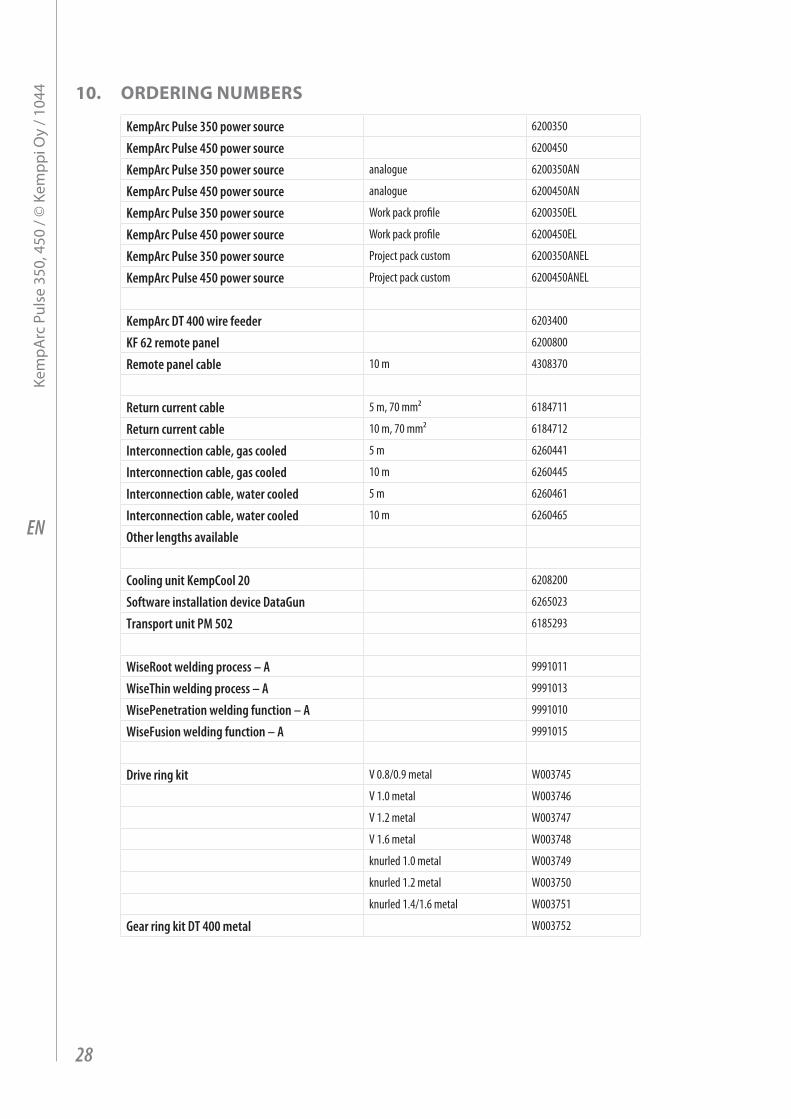
10. ordErIng numBErs
KempArc Pulse 350 power source 6200350
KempArc Pulse 450 power source 6200450
KempArc Pulse 350 power source analogue 6200350AN
KempArc Pulse 450 power source analogue 6200450AN
KempArc Pulse 350 power source Work pack profile 6200350EL
KempArc Pulse 450 power source Work pack profile 6200450EL
KempArc Pulse 350 power source Project pack custom 6200350ANEL
KempArc Pulse 450 power source Project pack custom 6200450ANEL
KempArc DT 400 wire feeder 6203400
KF 62 remote panel 6200800
Remote panel cable 10 m 4308370
Return current cable 5 m, 70 mm² 6184711
Return current cable 10 m, 70 mm² 6184712
Interconnection cable, gas cooled 5 m 6260441
Interconnection cable, gas cooled 10 m 6260445
Interconnection cable, water cooled 5 m 6260461
Interconnection cable, water cooled 10 m 6260465
Other lengths available
Cooling unit KempCool 20 6208200
Software installation device DataGun 6265023
Transport unit PM 502 6185293
WiseRoot welding process – A 9991011
WiseThin welding process – A 9991013
WisePenetration welding function – A 9991010
WiseFusion welding function – A 9991015
Drive ring kit V 0.8/0.9 metal W003745
V 1.0 metal W003746
V 1.2 metal W003747
V 1.6 metal W003748
knurled 1.0 metal W003749
knurled 1.2 metal W003750
knurled 1.4/1.6 metal W003751
Gear ring kit DT 400 metal W003752
28
Kem
parc
pul
se 3
50, 4
50 /
© K
empp
i Oy
/ 104
4
EN
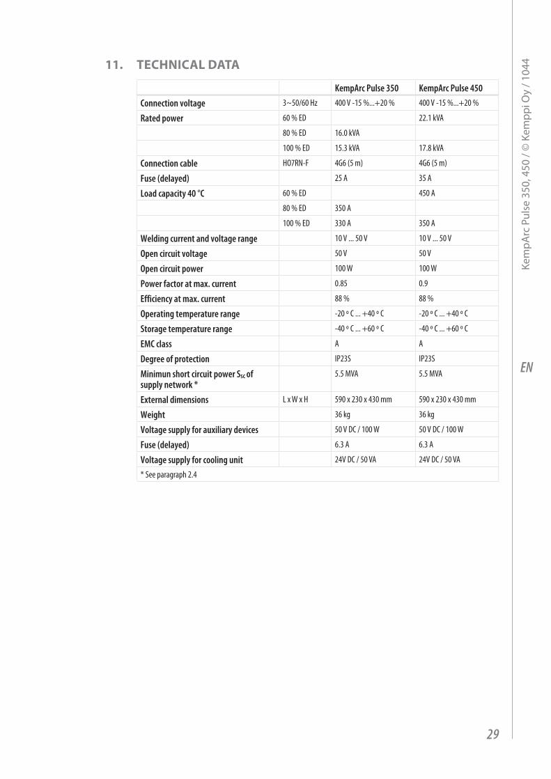
11. tEChnICAl dAtA
KempArc Pulse 350 KempArc Pulse 450Connection voltage 3~50/60 Hz 400 V -15 %...+20 % 400 V -15 %...+20 %
Rated power 60 % ED 22.1 kVA
80 % ED 16.0 kVA
100 % ED 15.3 kVA 17.8 kVA
Connection cable HO7RN-F 4G6 (5 m) 4G6 (5 m)
Fuse (delayed) 25 A 35 A
Load capacity 40 °C 60 % ED 450 A
80 % ED 350 A
100 % ED 330 A 350 A
Welding current and voltage range 10 V ... 50 V 10 V ... 50 V
Open circuit voltage 50 V 50 V
Open circuit power 100 W 100 W
Power factor at max. current 0.85 0.9
Efficiency at max. current 88 % 88 %
Operating temperature range -20 º C ... +40 º C -20 º C ... +40 º C
Storage temperature range -40 º C ... +60 º C -40 º C ... +60 º C
EMC class A A
Degree of protection IP23S IP23S
Minimun short circuit power Ssc of supply network *
5.5 MVA 5.5 MVA
External dimensions L x W x H 590 x 230 x 430 mm 590 x 230 x 430 mm
Weight 36 kg 36 kg
Voltage supply for auxiliary devices 50 V DC / 100 W 50 V DC / 100 W
Fuse (delayed) 6.3 A 6.3 A
Voltage supply for cooling unit 24V DC / 50 VA 24V DC / 50 VA
* See paragraph 2.4
29
Kem
parc
pul
se 3
50, 4
50 /
© K
empp
i Oy
/ 104
4
EN
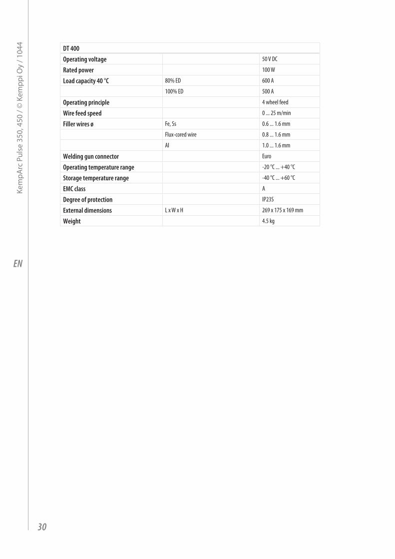
DT 400Operating voltage 50 V DC
Rated power 100 W
Load capacity 40 °C 80% ED 600 A
100% ED 500 A
Operating principle 4 wheel feed
Wire feed speed 0 ... 25 m/min
Filler wires ø Fe, Ss 0.6 ... 1.6 mm
Flux-cored wire 0.8 ... 1.6 mm
Al 1.0 ... 1.6 mm
Welding gun connector Euro
Operating temperature range -20 °C ... +40 °C
Storage temperature range -40 °C ... +60 °C
EMC class A
Degree of protection IP23S
External dimensions L x W x H 269 x 175 x 169 mm
Weight 4.5 kg
30
Kem
parc
pul
se 3
50, 4
50 /
© K
empp
i Oy
/ 104
4

www.kemppi.com 1920150 1044
KEMPPI OYHennalankatu 39PL 13FIN-15801 LAHTIFINLANDTel +358 3 899 11Telefax +358 3 899 [email protected]
Kotimaan myynti:Tel +358 3 899 11Telefax +358 3 734 [email protected]
KEMPPI SVERIGE ABBox 717S-194 27 UPPLANDS VÄSBYSVERIGETel +46 8 590 783 00Telefax +46 8 590 823 [email protected]
KEMPPI NORGE A/SPostboks 2151, PostterminalenN-3103 TØNSBERGNORGETel +47 33 346000Telefax +47 33 [email protected]
KEMPPI DANMARK A/SLiterbuen 11DK-2740 SKOVLUNDEDANMARKTel +45 4494 1677Telefax +45 4494 [email protected]
KEMPPI BENELUX B.V.Postbus 5603NL-4801 EA BREDANEDERLANDTel +31 765717750Telefax +31 [email protected]
KEMPPI (UK) LtdMartti Kemppi BuildingFraser RoadPriory Business ParkBEDFORD, MK44 3WHENGLANDTel +44 (0)845 6444201Telefax +44 (0)845 [email protected]
KEMPPI FRANCE S.A.S.65 Avenue de la Couronne des Prés78681 EPONE CEDEXFRANCETel +33 1 30 90 04 40Telefax +33 1 30 90 04 [email protected]
KEMPPI GmbHOtto-Hahn-Straße 14D-35510 BUTZBACHDEUTSCHLANDTel +49 6033 88 020Telefax +49 6033 72 [email protected]
KEMPPI SPÓŁKA Z O.O.Ul. Borzymowska 3203-565 WARSZAWAPOLANDTel +48 22 7816162Telefax +48 22 [email protected]
KEMPPI AUSTRALIA PTY LTD.13 Cullen PlaceP.O. Box 5256, Greystanes NSW 2145SMITHFIELD NSW 2164 AUSTRALIATel. +61 2 9605 9500Telefax +61 2 9605 [email protected]
OOO KEMPPIPolkovaya str. 1, Building 6127018 MOSCOWRUSSIATel +7 495 739 4304Telefax +7 495 739 [email protected]
ООО КЕМППИул. Полковая 1, строение 6127018 МоскваTel +7 495 739 4304Telefax +7 495 739 [email protected]
KEMPPI, TRADING (BEIJING) COMPANY, LIMITEDRoom 420, 3 Zone, Building B,No.12 Hongda North Street,Beijing Economic Development Zone,100176 BeijingCHINATel +86-10-6787 6064+86-10-6787 1282Telefax +86-10-6787 [email protected]
肯倍贸易(北京)有限公司中国北京经济技术开发区宏达北路12号创新大厦B座三区420室 (100176)电话: +86-10-6787 6064+86-10-6787 1282传真: +86-10-6787 [email protected]
KEMPPI INDIA PVT LTDLAKSHMI TOWERSNew No. 2/770, First Main Road, KAZURA Gardens, Neelangarai, CHENNAI - 600 041 TAMIL NADUTel +91-44-4567 1200Telefax +91-44-4567 [email protected]