Embed Size (px)
Citation preview
11[文書のタイトルを入力] 1
KEYENCE Machine Vision System
MODEL:CV-X Series
Introduction
This document is a user's manual for the provider to use "KEYENCE Machine Vision System CV-X Series" connected to the DENSO robot controller RC8 series.
Caution: (1) Note that the functions and performance cannot be guaranteed if this product is used
without observing instructions in this manual.
(2) All products and company names mentioned are trademarks or registered trademarks of
their respective holders.
---------------------------------------------------------------------------------------
This document targets the following models in CV-X series. (as of June, 2014)
KEYENCE CV-X100 Series
In this document, the above models are called CV-X series.
---------------------------------------------------------------------------------------
Important
To ensure proper and safe operation, be sure to read "Safety Precautions Manual" before using the provider.
Notice to Customers 1. Risks associated with using this product
The user of this product shall be responsible for embedding and using the product (software) on a system and any result from using it.
Contents
Introduction ........................................................................................................................................................................... 2 Important ............................................................................................................................................................................... 2 Notice to Customers .............................................................................................................................................................. 2 1. Outline of This Product ( Provider ) ............................................................................................................................. 4
1.1. Target device of provider ...................................................................................................................................... 4 1.2. Features of provider .............................................................................................................................................. 4 1.3. Mechanism of provider ......................................................................................................................................... 5
2. How to Connect ............................................................................................................................................................ 6 2.1. Ethernet Connection Example............................................................................................................................... 6 2.2. RS232C Connection Example............................................................................................................................... 6
3. Communication settings ................................................................................................................................................ 7 3.1. Setup for Ethernet connection ............................................................................................................................... 7
3.1.1. Communication setting for CV-X series ....................................................................................................... 7 3.1.2. Communication setting for Robot controller ................................................................................................ 9
3.2. Setup for RS232C connection ............................................................................................................................. 10 3.2.1. Communication setting for CV-X Series ..................................................................................................... 10 3.2.2. Communication setting for Robot controller .............................................................................................. 10
4. Provider Execution Procedure .................................................................................................................................... 11 5. Command Description ................................................................................................................................................ 12
Table 5-1 Command list .................................................................................................................................................. 13
6. Error Code ................................................................................................................................................................... 38 7. Sample Program .......................................................................................................................................................... 38 Revision History ................................................................................................................................................................. 39
4
Machine Vision System / CV-X Series
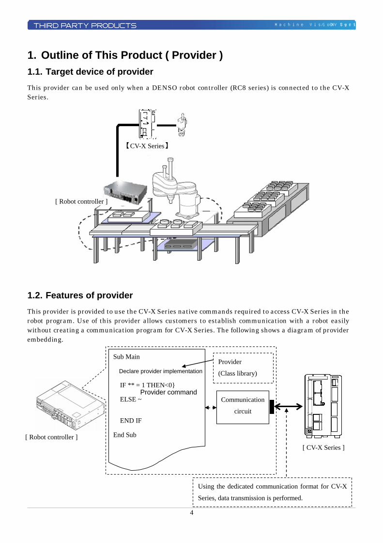
1. Outline of This Product ( Provider ) 1.1. Target device of provider This provider can be used only when a DENSO robot controller (RC8 series) is connected to the CV-X Series.
1.2. Features of provider This provider is provided to use the CV-X Series native commands required to access CV-X Series in the robot program. Use of this provider allows customers to establish communication with a robot easily without creating a communication program for CV-X Series. The following shows a diagram of provider embedding.
【CV-X Series】
[ Robot controller ]
[ Robot controller ]
Using the dedicated communication format for CV-X
Series, data transmission is performed.
Provider
(Class library)
[ CV-X Series ]
Sub Main Declare provider implementation
IF ** = 1 THEN<0} Provider command
ELSE ~ û û
END IF End Sub
Communication
circuit
5
Machine Vision System / CV-X Series
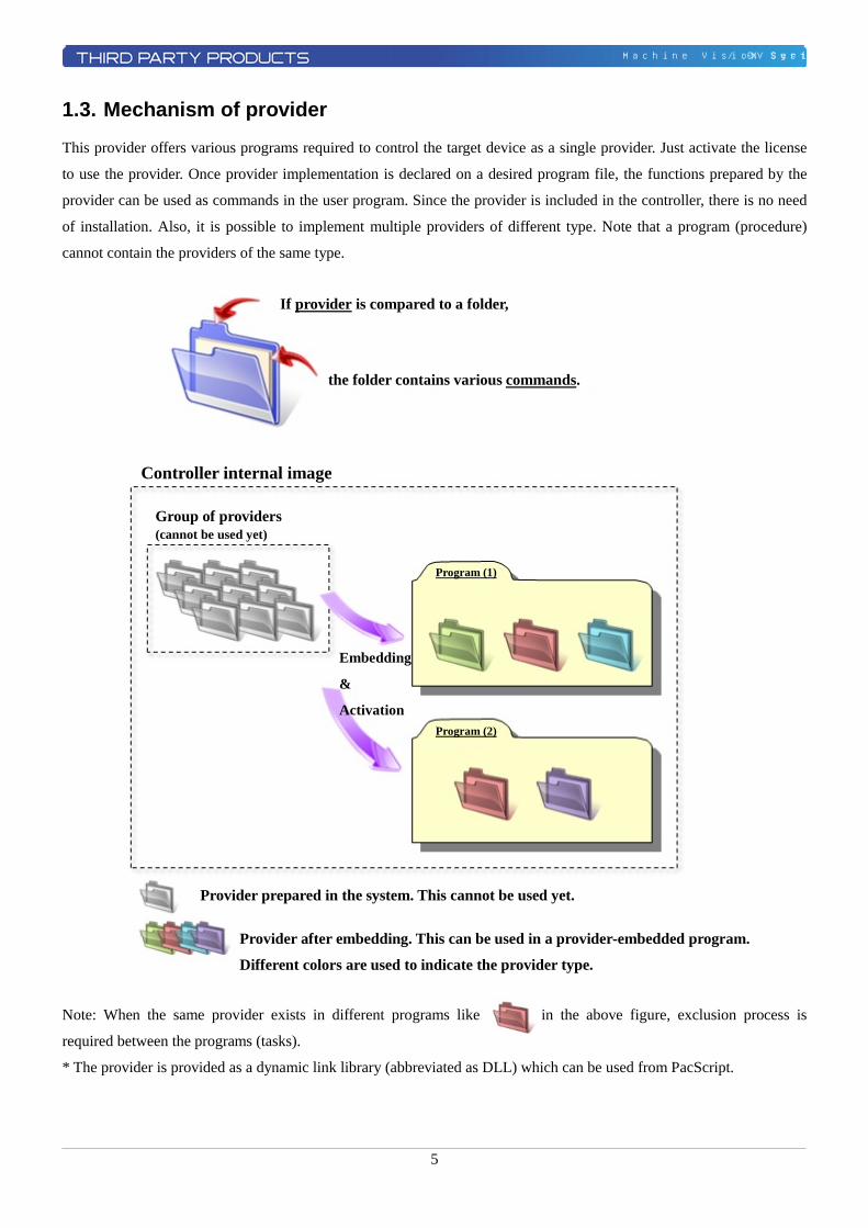
1.3. Mechanism of provider
This provider offers various programs required to control the target device as a single provider. Just activate the license
to use the provider. Once provider implementation is declared on a desired program file, the functions prepared by the
provider can be used as commands in the user program. Since the provider is included in the controller, there is no need
of installation. Also, it is possible to implement multiple providers of different type. Note that a program (procedure)
cannot contain the providers of the same type.
Note: When the same provider exists in different programs like in the above figure, exclusion process is
required between the programs (tasks).
* The provider is provided as a dynamic link library (abbreviated as DLL) which can be used from PacScript.
If provider is compared to a folder,
the folder contains various commands.
Controller internal image
Group of providers (cannot be used yet)
Program (1)
Program (2)
Embedding
&
Activation
Provider prepared in the system. This cannot be used yet.
Provider after embedding. This can be used in a provider-embedded program.
Different colors are used to indicate the provider type.
6
Machine Vision System / CV-X Series
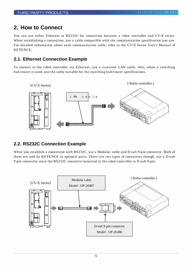
2. How to Connect You can use either Ethernet or RS232C for connection between a robot controller and CV-X series. When establishing a connection, use a cable compatible with the communication specification you use. For detailed information about each communication cable, refer to the CV-X Series User's Manual of KEYENCE. 2.1. Ethernet Connection Example To connect to the robot controller via Ethernet, use a crossover LAN cable. Also, when a switching hub/router is used, use the cable suitable for the switching hub/router specifications.
2.2. RS232C Connection Example When you establish a connection with RS232C, use a Modular cable and D-sub 9-pin connector. Both of them are sold by KEYENCE as optional parts. There are two types of connectors though, use a D-sub 9-pin connector since the RS232C connector mounted in the robot controller is D-sub 9-pin.
[CV-X Series]
[ Robot controller ]
LAN cable
Modular cable
Model : OP-26487
D-sub 9-pin connector
Model : OP-26486
[ Robot controller ] [CV-X Series]
7
Machine Vision System / CV-X Series
3. Communication settings 3.1. Setup for Ethernet connection 3.1.1. Communication setting for CV-X series
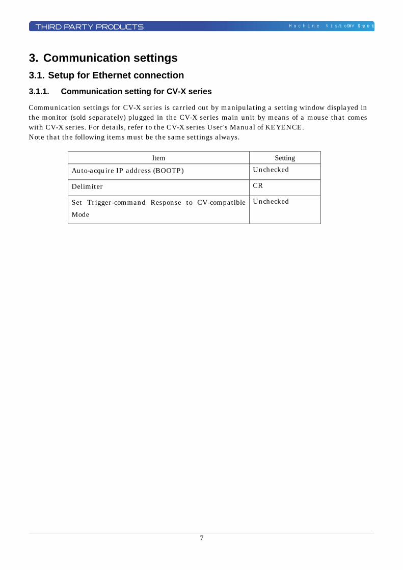
Communication settings for CV-X series is carried out by manipulating a setting window displayed in the monitor (sold separately) plugged in the CV-X series main unit by means of a mouse that comes with CV-X series. For details, refer to the CV-X series User's Manual of KEYENCE. Note that the following items must be the same settings always.
Item Setting
Auto-acquire IP address (BOOTP) Unchecked
Delimiter CR
Set Trigger-command Response to CV-compatible Mode
Unchecked
8
Machine Vision System / CV-X Series
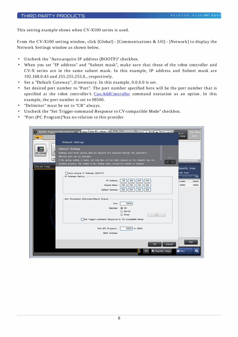
This setting example shows when CV-X100 series is used. From the CV-X100 setting window, click [Global] - [Communications & I/O] - [Network] to display the Network Settings window as shown below. ・ Uncheck the "Auto-acquire IP address (BOOTP)" checkbox. ・ When you set "IP address" and "Subnet mask", make sure that these of the robot controller and
CV-X series are in the same subnet mask. In this example, IP address and Subnet mask are 192.168.0.43 and 255.255.255.0., respectively.
・ Set a "Default Gateway", if necessary. In this example, 0.0.0.0 is set. ・ Set desired port number to "Port". The port number specified here will be the port number that is
specified at the robot controller’s Cao.AddController command execution as an option. In this example, the port number is set to 08500.
・ "Delimiter" must be set to "CR" always. ・ Uncheck the "Set Trigger-command Response to CV-compatible Mode" checkbox. ・ "Port (PC Program)"has no relation to this provider
9
Machine Vision System / CV-X Series
3.1.2. Communication setting for Robot controller
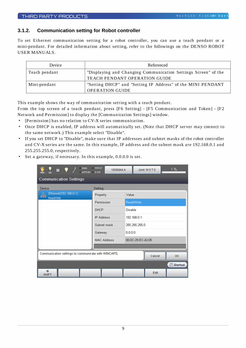
To set Ethernet communication setting for a robot controller, you can use a teach pendant or a mini-pendant. For detailed information about setting, refer to the followings on the DENSO ROBOT USER MANUALS.
Device Referenced Teach pendant "Displaying and Changing Communication Settings Screen" of the
TEACH PENDANT OPERATION GUIDE Mini-pendant "Setting DHCP" and "Setting IP Address" of the MINI PENDANT
OPERATION GUIDE This example shows the way of communication setting with a teach pendant. From the top screen of a teach pendant, press [F6 Setting] - [F5 Communication and Token] - [F2 Network and Permission] to display the [Communication Settings] window. ・ [Permission] has no relation to CV-X series communication. ・ Once DHCP is enabled, IP address will automatically set. (Note that DHCP server may connect to
the same network.) This example select "Disable". ・ If you set DHCP to "Disable", make sure that IP addresses and subnet masks of the robot controller
and CV-X series are the same. In this example, IP address and the subnet mask are 192.168.0.1 and 255.255.255.0, respectively.
・ Set a gateway, if necessary. In this example, 0.0.0.0 is set.
10
Machine Vision System / CV-X Series
3.2. Setup for RS232C connection 3.2.1. Communication setting for CV-X Series
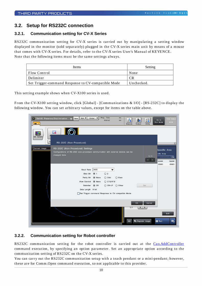
RS232C communication setting for CV-X series is carried out by manipulating a setting window displayed in the monitor (sold separately) plugged in the CV-X series main unit by means of a mouse that comes with CV-X series. For details, refer to the CV-X series User's Manual of KEYENCE. Note that the following items must be the same settings always.
Items Setting Flow Control None Delimiter CR Set Trigger-command Response to CV-compatible Mode Unchecked.
This setting example shows when CV-X100 series is used. From the CV-X100 setting window, click [Global] - [Communications & I/O] - [RS-232C] to display the following window. You can set arbitrary values, except for items on the table above. 3.2.2. Communication setting for Robot controller
RS232C communication setting for the robot controller is carried out at the Cao.AddController command execution, by specifying an option parameter. Set an appropriate option according to the communication setting of RS232C on the CV-X series. You can carry out the RS232C communication setup with a teach pendant or a mini-pendant; however, these are for Comm.Open command execution, so not applicable to this provider.
11
Machine Vision System / CV-X Series
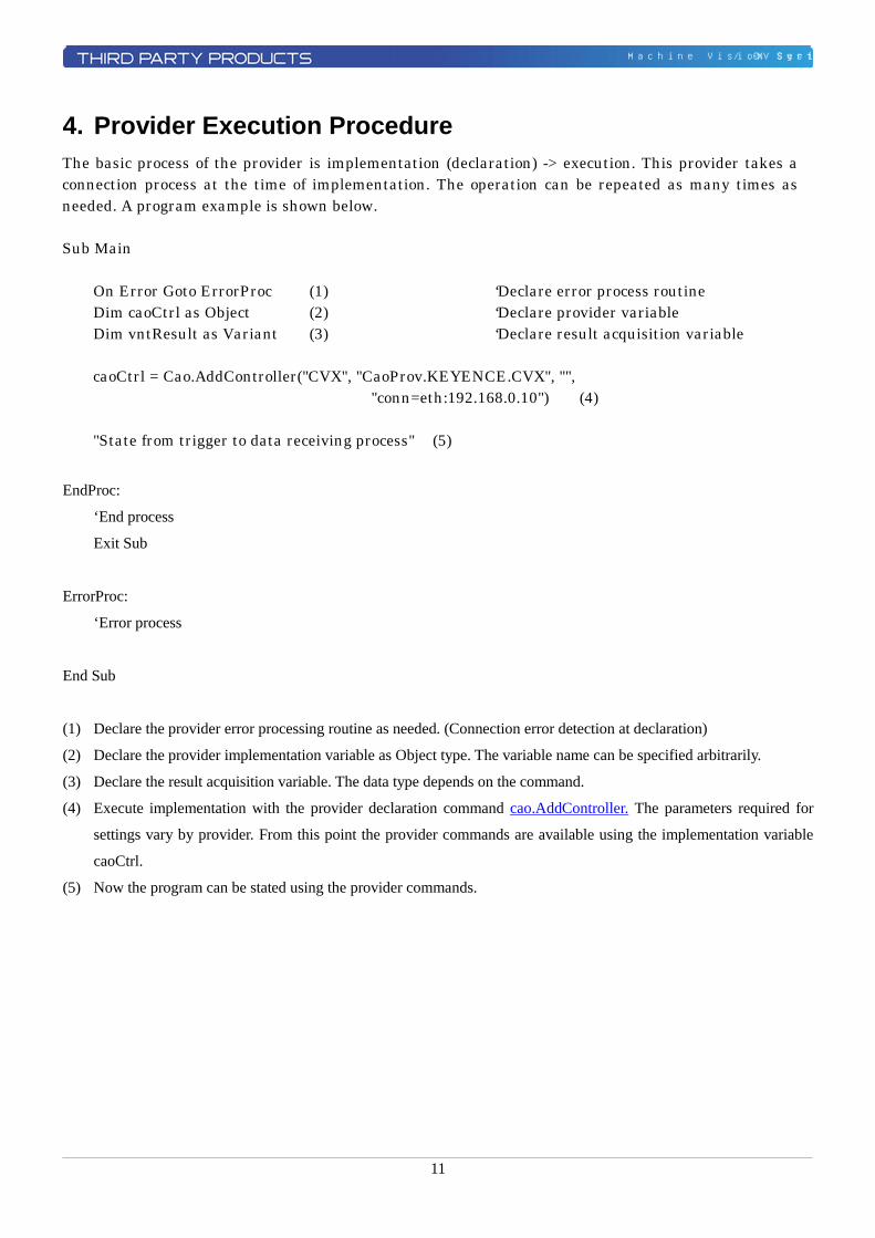
4. Provider Execution Procedure The basic process of the provider is implementation (declaration) -> execution. This provider takes a connection process at the time of implementation. The operation can be repeated as many times as needed. A program example is shown below. Sub Main
On Error Goto ErrorProc (1) ‘Declare error process routine Dim caoCtrl as Object (2) ‘Declare provider variable Dim vntResult as Variant (3) ‘Declare result acquisition variable
caoCtrl = Cao.AddController("CVX", "CaoProv.KEYENCE.CVX", "",
"conn=eth:192.168.0.10") (4) "State from trigger to data receiving process" (5)
EndProc:
‘End process
Exit Sub
ErrorProc:
‘Error process
End Sub
(1) Declare the provider error processing routine as needed. (Connection error detection at declaration)
(2) Declare the provider implementation variable as Object type. The variable name can be specified arbitrarily.
(3) Declare the result acquisition variable. The data type depends on the command.
(4) Execute implementation with the provider declaration command cao.AddController. The parameters required for
settings vary by provider. From this point the provider commands are available using the implementation variable
caoCtrl.
(5) Now the program can be stated using the provider commands.
12
Machine Vision System / CV-X Series
5. Command Description This page contains a description of commands. Commands are classified the following three types. ・ Connection commands ・ CV-X series-supported command ・ Proprietary extension commands A CV-X series-supported command is the command that is paired with a CV-X series command. The correspondence between the CV-X series commands and the CV-X series-supported commands is shown in the command list on the next page. For the detailed operation of CV-X Series commands, refer to the CV-X Series User's manual of KEYENCE.
13
Machine Vision System / CV-X Series
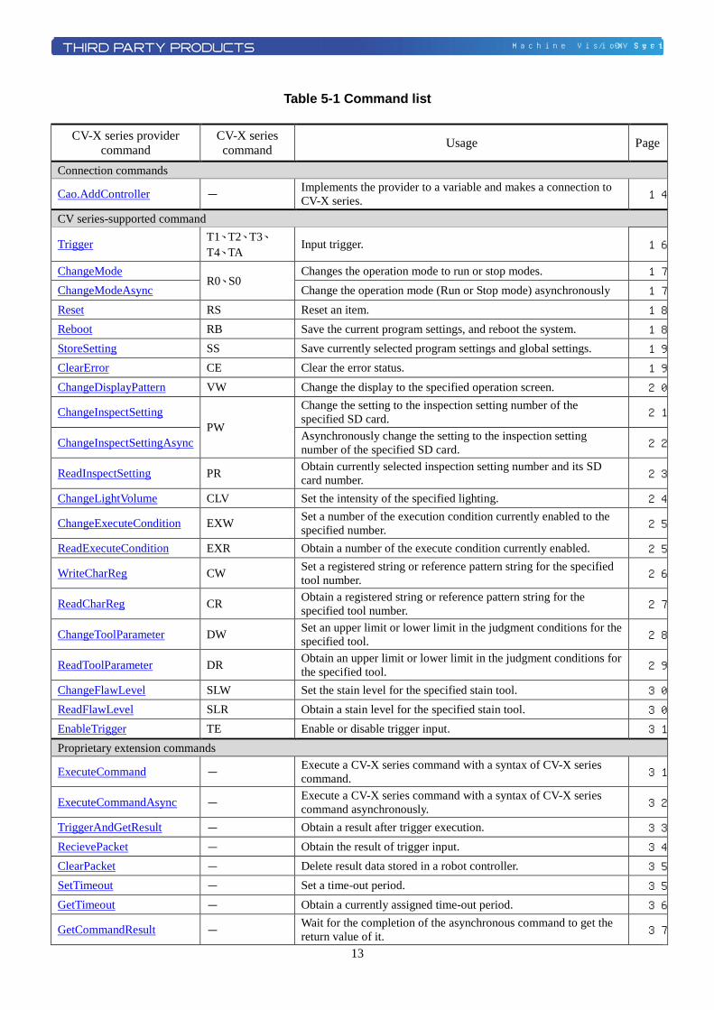
Table 5-1 Command list
CV-X series provider command
CV-X series command Usage Page
Connection commands
Cao.AddController - Implements the provider to a variable and makes a connection to CV-X series. 14
CV series-supported command
Trigger T1、T2、T3、T4、TA
Input trigger. 16
ChangeMode R0、S0
Changes the operation mode to run or stop modes. 17
ChangeModeAsync Change the operation mode (Run or Stop mode) asynchronously 17
Reset RS Reset an item. 18
Reboot RB Save the current program settings, and reboot the system. 18
StoreSetting SS Save currently selected program settings and global settings. 19
ClearError CE Clear the error status. 19
ChangeDisplayPattern VW Change the display to the specified operation screen. 20
ChangeInspectSetting PW
Change the setting to the inspection setting number of the specified SD card. 21
ChangeInspectSettingAsync Asynchronously change the setting to the inspection setting number of the specified SD card. 22
ReadInspectSetting PR Obtain currently selected inspection setting number and its SD card number. 23
ChangeLightVolume CLV Set the intensity of the specified lighting. 24
ChangeExecuteCondition EXW Set a number of the execution condition currently enabled to the specified number. 25
ReadExecuteCondition EXR Obtain a number of the execute condition currently enabled. 25
WriteCharReg CW Set a registered string or reference pattern string for the specified tool number. 26
ReadCharReg CR Obtain a registered string or reference pattern string for the specified tool number. 27
ChangeToolParameter DW Set an upper limit or lower limit in the judgment conditions for the specified tool. 28
ReadToolParameter DR Obtain an upper limit or lower limit in the judgment conditions for the specified tool. 29
ChangeFlawLevel SLW Set the stain level for the specified stain tool. 30
ReadFlawLevel SLR Obtain a stain level for the specified stain tool. 30
EnableTrigger TE Enable or disable trigger input. 31
Proprietary extension commands
ExecuteCommand - Execute a CV-X series command with a syntax of CV-X series command. 31
ExecuteCommandAsync - Execute a CV-X series command with a syntax of CV-X series command asynchronously. 32
TriggerAndGetResult - Obtain a result after trigger execution. 33
RecievePacket - Obtain the result of trigger input. 34
ClearPacket - Delete result data stored in a robot controller. 35
SetTimeout - Set a time-out period. 35
GetTimeout - Obtain a currently assigned time-out period. 36
GetCommandResult - Wait for the completion of the asynchronous command to get the return value of it. 37
14
Machine Vision System / CV-X Series
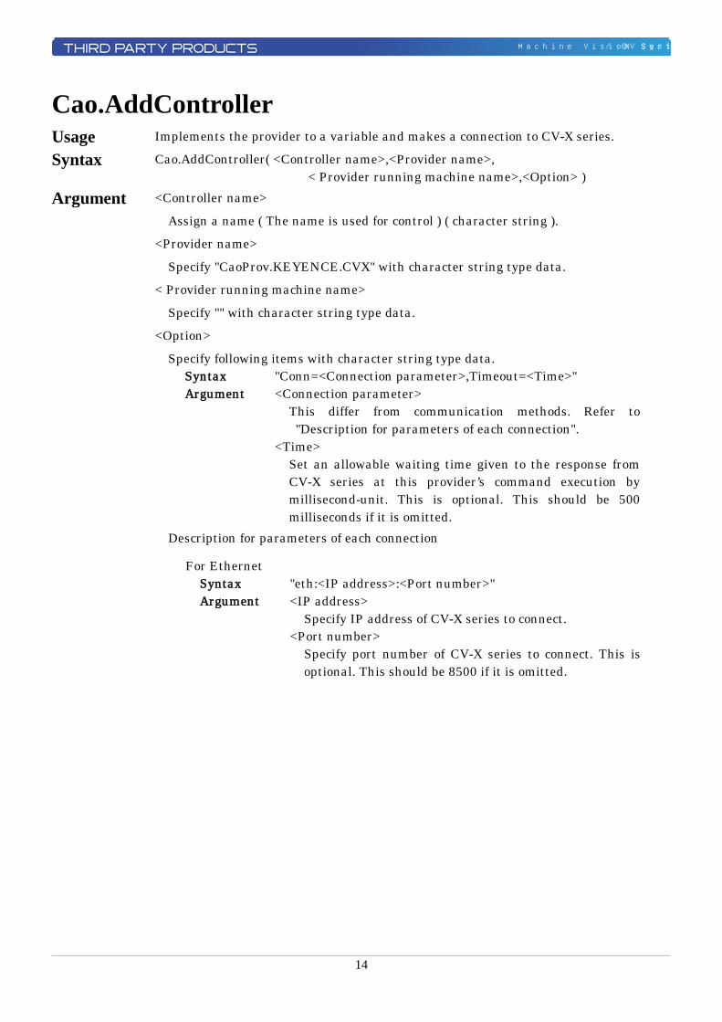
Cao.AddController Usage Implements the provider to a variable and makes a connection to CV-X series.
Syntax Cao.AddController( <Controller name>,<Provider name>, < Provider running machine name>,<Option> )
Argument <Controller name>
Assign a name ( The name is used for control ) ( character string ).
<Provider name>
Specify "CaoProv.KEYENCE.CVX" with character string type data.
< Provider running machine name>
Specify "" with character string type data.
<Option>
Specify following items with character string type data. Syntax "Conn=<Connection parameter>,Timeout=<Time>" Argument <Connection parameter> This differ from communication methods. Refer to
"Description for parameters of each connection". <Time> Set an allowable waiting time given to the response from
CV-X series at this provider’s command execution by millisecond-unit. This is optional. This should be 500 milliseconds if it is omitted.
Description for parameters of each connection
For Ethernet Syntax "eth:<IP address>:<Port number>" Argument <IP address> Specify IP address of CV-X series to connect. <Port number> Specify port number of CV-X series to connect. This is
optional. This should be 8500 if it is omitted.
15
Machine Vision System / CV-X Series
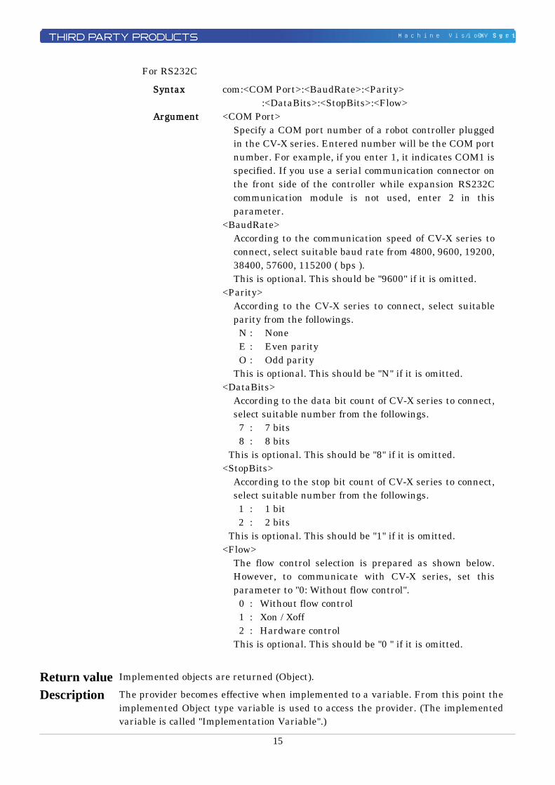
For RS232C
Syntax com:<COM Port>:<BaudRate>:<Parity> :<DataBits>:<StopBits>:<Flow>
Argument <COM Port> Specify a COM port number of a robot controller plugged
in the CV-X series. Entered number will be the COM port number. For example, if you enter 1, it indicates COM1 is specified. If you use a serial communication connector on the front side of the controller while expansion RS232C communication module is not used, enter 2 in this parameter.
<BaudRate> According to the communication speed of CV-X series to
connect, select suitable baud rate from 4800, 9600, 19200, 38400, 57600, 115200 ( bps ). This is optional. This should be "9600" if it is omitted.
<Parity> According to the CV-X series to connect, select suitable
parity from the followings. N : None E : Even parity O : Odd parity This is optional. This should be "N" if it is omitted. <DataBits> According to the data bit count of CV-X series to connect,
select suitable number from the followings. 7 : 7 bits 8 : 8 bits This is optional. This should be "8" if it is omitted. <StopBits> According to the stop bit count of CV-X series to connect,
select suitable number from the followings. 1 : 1 bit 2 : 2 bits This is optional. This should be "1" if it is omitted. <Flow> The flow control selection is prepared as shown below.
However, to communicate with CV-X series, set this parameter to "0: Without flow control".
0 : Without flow control 1 : Xon / Xoff 2 : Hardware control This is optional. This should be "0 " if it is omitted.
Return value Implemented objects are returned (Object).
Description The provider becomes effective when implemented to a variable. From this point the implemented Object type variable is used to access the provider. (The implemented variable is called "Implementation Variable".)
16
Machine Vision System / CV-X Series
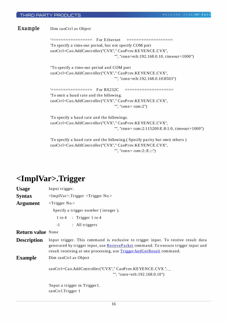
Example Dim caoCtrl as Object '================= For Ethernet =================== 'To specify a time-out period, but not specify COM port caoCtrl=Cao.AddController("CVX"," CaoProv.KEYENCE.CVX", "", "conn=eth:192.168.0.10, timeout=1000") ''To specify a time-out period and COM port caoCtrl=Cao.AddController("CVX"," CaoProv.KEYENCE.CVX", "", "conn=eth:192.168.0.10:8503") '================= For RS232C ==================== 'To omit a baud rate and the following. caoCtrl=Cao.AddController("CVX"," CaoProv.KEYENCE.CVX", "", "conn= com:2") 'To specify a baud rate and the followings. caoCtrl=Cao.AddController("CVX"," CaoProv.KEYENCE.CVX", "", "conn= com:2:115200:E:8:1:0, timeout=1000") 'To specify a baud rate and the following.( Specify parity but omit others ) caoCtrl=Cao.AddController("CVX"," CaoProv.KEYENCE.CVX", "", "conn= com:2::E:::")
<ImplVar>.Trigger Usage Input trigger.
Syntax <ImplVar>.Trigger <Trigger No.>
Argument <Trigger No.>
Specify a trigger number ( integer ).
1 to 4 : Trigger 1 to 4
-1 : All triggers
Return value None
Description Input trigger. This command is exclusive to trigger input. To receive result data generated by trigger input, use RecievePacket command. To execute trigger input and result receiving at one processing, use TriggerAndGetResult command.
Example Dim caoCtrl as Object caoCtrl=Cao.AddController("CVX"," CaoProv.KEYENCE.CVX ", _ "", "conn=eth:192.168.0.10") 'Input a trigger in Trigger1. caoCtrl.Trigger 1
17
Machine Vision System / CV-X Series
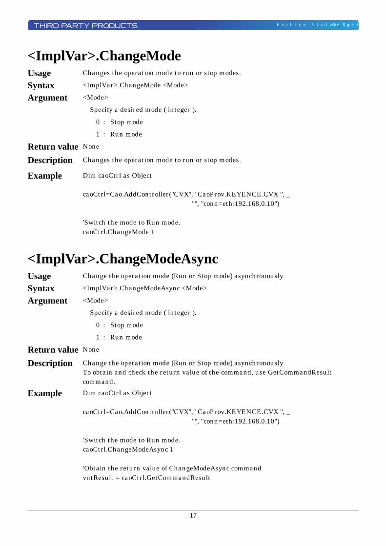
<ImplVar>.ChangeMode Usage Changes the operation mode to run or stop modes.
Syntax <ImplVar>.ChangeMode <Mode>
Argument <Mode>
Specify a desired mode ( integer ).
0 : Stop mode
1 : Run mode
Return value None
Description Changes the operation mode to run or stop modes.
Example Dim caoCtrl as Object caoCtrl=Cao.AddController("CVX"," CaoProv.KEYENCE.CVX ", _ "", "conn=eth:192.168.0.10") 'Switch the mode to Run mode. caoCtrl.ChangeMode 1
<ImplVar>.ChangeModeAsync Usage Change the operation mode (Run or Stop mode) asynchronously
Syntax <ImplVar>.ChangeModeAsync <Mode>
Argument <Mode>
Specify a desired mode ( integer ).
0 : Stop mode
1 : Run mode
Return value None
Description Change the operation mode (Run or Stop mode) asynchronously To obtain and check the return value of the command, use GetCommandResult command.
Example Dim caoCtrl as Object caoCtrl=Cao.AddController("CVX"," CaoProv.KEYENCE.CVX ", _ "", "conn=eth:192.168.0.10") 'Switch the mode to Run mode. caoCtrl.ChangeModeAsync 1 'Obtain the return value of ChangeModeAsync command vntResult = caoCtrl.GetCommandResult
18
Machine Vision System / CV-X Series
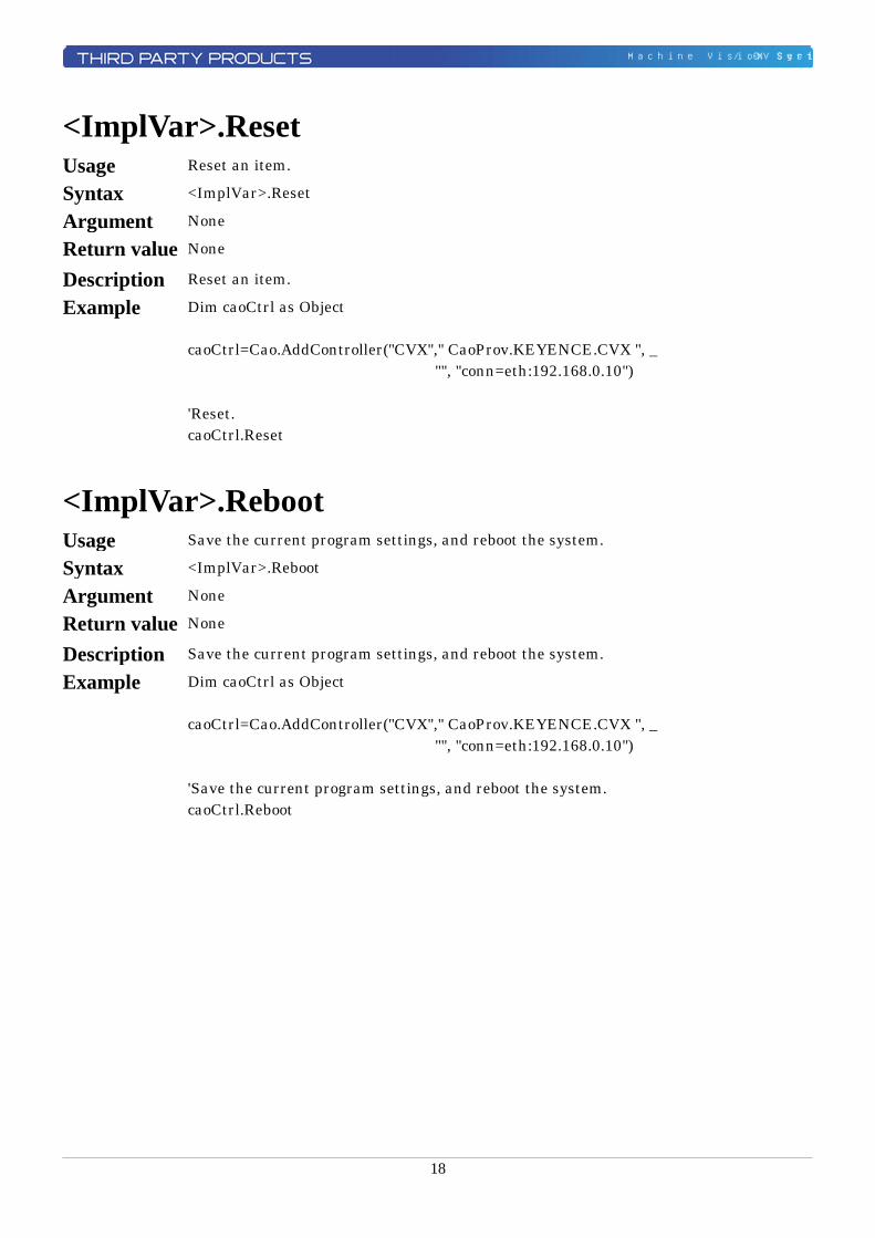
<ImplVar>.Reset Usage Reset an item.
Syntax <ImplVar>.Reset
Argument None
Return value None
Description Reset an item.
Example Dim caoCtrl as Object caoCtrl=Cao.AddController("CVX"," CaoProv.KEYENCE.CVX ", _ "", "conn=eth:192.168.0.10") 'Reset. caoCtrl.Reset
<ImplVar>.Reboot Usage Save the current program settings, and reboot the system.
Syntax <ImplVar>.Reboot
Argument None
Return value None
Description Save the current program settings, and reboot the system.
Example Dim caoCtrl as Object caoCtrl=Cao.AddController("CVX"," CaoProv.KEYENCE.CVX ", _ "", "conn=eth:192.168.0.10") 'Save the current program settings, and reboot the system. caoCtrl.Reboot
19
Machine Vision System / CV-X Series
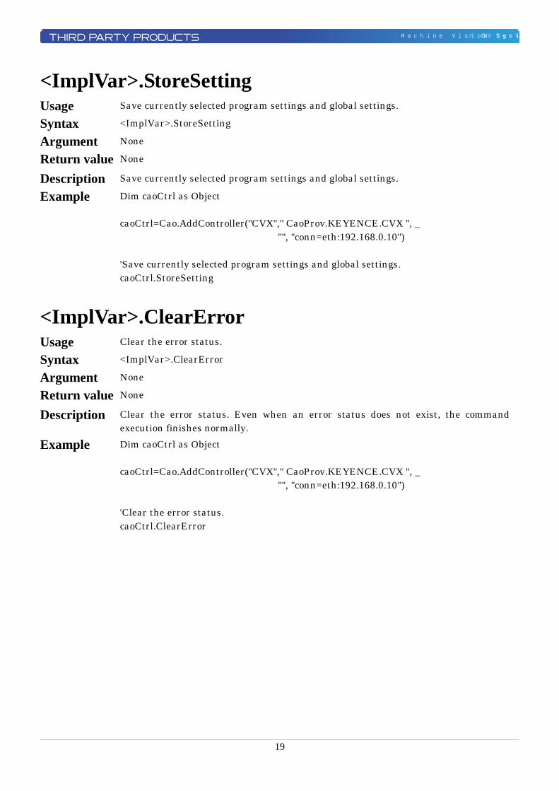
<ImplVar>.StoreSetting Usage Save currently selected program settings and global settings.
Syntax <ImplVar>.StoreSetting
Argument None
Return value None
Description Save currently selected program settings and global settings.
Example Dim caoCtrl as Object caoCtrl=Cao.AddController("CVX"," CaoProv.KEYENCE.CVX ", _ "", "conn=eth:192.168.0.10") 'Save currently selected program settings and global settings. caoCtrl.StoreSetting
<ImplVar>.ClearError Usage Clear the error status.
Syntax <ImplVar>.ClearError
Argument None
Return value None
Description Clear the error status. Even when an error status does not exist, the command execution finishes normally.
Example Dim caoCtrl as Object caoCtrl=Cao.AddController("CVX"," CaoProv.KEYENCE.CVX ", _ "", "conn=eth:192.168.0.10") 'Clear the error status. caoCtrl.ClearError
20
Machine Vision System / CV-X Series
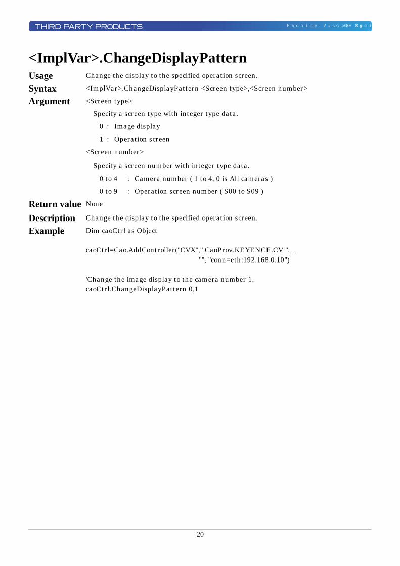
<ImplVar>.ChangeDisplayPattern Usage Change the display to the specified operation screen.
Syntax <ImplVar>.ChangeDisplayPattern <Screen type>,<Screen number>
Argument <Screen type>
Specify a screen type with integer type data.
0 : Image display
1 : Operation screen
<Screen number>
Specify a screen number with integer type data.
0 to 4 : Camera number ( 1 to 4, 0 is All cameras )
0 to 9 : Operation screen number ( S00 to S09 )
Return value None
Description Change the display to the specified operation screen.
Example Dim caoCtrl as Object caoCtrl=Cao.AddController("CVX"," CaoProv.KEYENCE.CV ", _ "", "conn=eth:192.168.0.10") 'Change the image display to the camera number 1. caoCtrl.ChangeDisplayPattern 0,1
21
Machine Vision System / CV-X Series
<ImplVar>.ChangeInspectSetting Usage Change the setting to the inspection setting number of the specified SD card.
Syntax <ImplVar>.ChangeInspectSetting <SD card number>,<Inspection setting number>
Argument <SD card number>
Specify an SD card number with integer type data .
1 : SD1
2 : SD2
<Inspection setting number>
Specify an inspection setting number with integer type data ranging from 0 to 999.
Return value None
Description Change the setting to the inspection setting number of the specified SD card.
Example Dim caoCtrl as Object caoCtrl=Cao.AddController("CVX"," CaoProv.KEYENCE.CVX ", _ "", "conn=eth:192.168.0.10") 'Change the setting to the inspection setting number 1 of the SD1. caoCtrl.ChangeInspectSetting 1,1
22
Machine Vision System / CV-X Series
<ImplVar>.ChangeInspectSettingAsync Usage Asynchronously change the setting to the inspection setting number of the specified
SD card. Syntax <ImplVar>.ChangeInspectSettingAsync <SD card number>,<Inspection setting
number> Argument <SD card number>
Specify an SD card number with integer type data .
1 : SD1
2 : SD2
<Inspection setting number>
Specify an inspection setting number with integer type data ranging from 0 to 999.
Return value None
Description Asynchronously change the setting to the inspection setting number of the specified SD card. To obtain and check the return value of the command, use GetCommandResult command.
Example Dim caoCtrl as Object caoCtrl=Cao.AddController("CVX"," CaoProv.KEYENCE.CVX ", _ "", "conn=eth:192.168.0.10") 'Change the setting to the inspection setting number 1 of the SD1. caoCtrl.ChangeInspectSettingAsync 1,1 'Obtain the return value of ChangeInspectionSettingAsync command vntResult = caoCtrl.GetCommandResult
23
Machine Vision System / CV-X Series
<ImplVar>.ReadInspectSetting Usage Obtain currently selected inspection setting number and its SD card number.
Syntax <ImplVar>.ReadInspectSetting
Argument None
Return value The following two items are stored in an array of integer.
<SD card number>
Currently selected SD card number
1 : SD1
2 : SD2
<Inspection setting number>
Currently selected inspection setting number.
Description Obtain currently selected inspection setting number and its SD card number.
Example Dim caoCtrl as Object Dim iaryData(1) as Integer caoCtrl=Cao.AddController("CVX"," CaoProv.KEYENCE.CVX ", _ "", "conn=eth:192.168.0.10") 'Obtain currently selected inspection setting number and its SD card number. 'iaryData(0) stores an SD card number. 'iaryData(1) stores an inspection setting number. iaryData = caoCtrl.ReadInspectSetting
24
Machine Vision System / CV-X Series
<ImplVar>.ChangeLightVolume Usage Set the intensity of the specified lighting.
Syntax <ImplVar>.ChangeLightVolume <Lighting No>,<Lighting intensity value>, <Capture count or capture point>, <Lighting for multiple image capture>
Argument <Lighting number>
Specify a lighting number with integer type data ranging from 1 to 8.
<Lighting intensity value>
Specify a lighting intensity value with integer type data ranging from 0 to 255.
<Capture count or capture point>
Specify a capture count or capture point with integer type data ranging from 1 to 8. This is optional. The capture count and capture point will not be changed if it is omitted.
<Lighting for multiple image capture>
Specify a lighting for multiple image capture with integer type data ranging from 1 to 2. This is optional. The lighting for multiple image capture will not be changed if it is omitted.
Return value None
Description Set the intensity of the specified lighting.
Example Dim caoCtrl as Object caoCtrl=Cao.AddController("CVX"," CaoProv.KEYENCE.CVX ", _ "", "conn=eth:192.168.0.10") 'Set the lighting intensity value of lighting number 1 to 30. caoCtrl.ChangeLightVolume 1,30
25
Machine Vision System / CV-X Series
<ImplVar>.ChangeExecuteCondition Usage Set a number of the execution condition currently enabled to the specified number.
Syntax <ImplVar>.ChangeExecuteCondition <Execute condition number>
Argument <Execute condition number>
Specify an execute condition number with integer type data ranging from 0 to 99.
Return value None
Description Set a number of the execution condition currently enabled to the specified number.
Example Dim caoCtrl as Object caoCtrl=Cao.AddController("CVX"," CaoProv.KEYENCE.CVX ", _ "", "conn=eth:192.168.0.10") 'Set the execute condition number to 1. caoCtrl.ChangeExecuteCondition 1
<ImplVar>.ReadExecuteCondition Usage Obtain a number of the execute condition currently enabled.
Syntax <ImplVar>.ReadExecuteCondition
Argument None
Return value <Execute condition number>
Currently enabled execute condition number is returned with integer type data.
Description Obtain a number of the execute condition currently enabled.
Example Dim caoCtrl as Object Dim iParam as Integer caoCtrl=Cao.AddController("CVX"," CaoProv.KEYENCE.CVX ", _ "", "conn=eth:192.168.0.10") 'Obtain a number of the execute condition currently enabled. iParam = caoCtrl.ReadExecuteCondition
26
Machine Vision System / CV-X Series
<ImplVar>.WriteCharReg Usage Set a registered string or reference pattern string for the specified tool number.
Syntax <ImplVar>.WriteCharReg <Tool No.>,<Line No. / Reference condition No.>, <Registered string / Reference pattern string>
Argument <Tool No.>
Specify a tool number with integer type data ranging from 100 to 499.
<Line No. / Reference condition No.>
Specify a line number or a reference condition number with integer type data. If a specified tool number is set to OCR tool, set 1. If specified tool number set to 1D code reader or 2D code reader, set 1 to 16.
<Registered string / Reference pattern string>
Specify a registered string or reference pattern string with character string type data.
Return value None
Description If a specified tool number set to OCR tool, a registered string is set. If a specified tool number set to 1D code reader or 2D code reader, a reference pattern string is set. When neither registered string nor reference pattern string is specified, the latest reading result is set.
Example Dim caoCtrl as Object caoCtrl=Cao.AddController("CVX"," CaoProv.KEYENCE.CVX ", _ "", "conn=eth:192.168.0.10") 'Set the No.101 OCR tool registered string to DEF. caoCtrl.WriteCharReg 101,1,"DEF"
27
Machine Vision System / CV-X Series
<ImplVar>.ReadCharReg Usage Obtain a registered string or reference pattern string for the specified tool number.
Syntax <ImplVar>.ReadCharReg <Tool No.>,<Line No. / Reference condition No.>
Argument <Tool No.>
Specify a tool number with integer type data ranging from 100 to 499.
<Line No. / Reference condition No.>
Specify a line number or a reference condition number with integer type data. If specified tool number set to OCR tool, set 1. If specified tool number set to 1D code reader or 2D code reader, set 1 to 16.
Return value <Registered string / Reference pattern string>
Registered string or reference pattern string you have specified is returned with character string type data.
Description If a specified tool number set to OCR tool, a registered string is returned. If a specified tool number set to 1D code reader or 2D code reader, a reference pattern string is returned.
Example Dim caoCtrl as Object Dim bstrParam as String caoCtrl=Cao.AddController("CVX"," CaoProv.KEYENCE.CVX ", _ "", "conn=eth:192.168.0.10") 'Obtain the No.101 OCR tool registered string. bstrParam = caoCtrl.WriteCharReg 101,1
28
Machine Vision System / CV-X Series
<ImplVar>.ChangeToolParameter Usage Set an upper limit or lower limit in the judgment conditions for the specified tool.
Syntax <ImplVar>.ChangeToolParameter <Tool No.>, <Item ID for judgment condition type>, <Upper limit / lower limit>, <Judgment condition value>
Argument <Tool No.>
Specify a tool number with integer type data .
<Item ID for judgment condition type>
Specify an item ID for judgment condition type with integer type data. For details, refer to the DW command of the KEYENCE CV-X Series User's Manual.
<Upper limit / lower limit>
Specify an upper limit or lower limit with integer type data .
0 : Upper limit
1 : Lower limit
<Judgment condition value>
Specify the Judgment condition value with character string type data .
Return value None
Description Set an upper limit or lower limit in the judgment conditions for the specified tool.
Example Dim caoCtrl as Object caoCtrl=Cao.AddController("CVX"," CaoProv.KEYENCE.CVX ", _ "", "conn=eth:192.168.0.10") 'Set the lower limit on the edge tool of the tool No.100 to 123.456. caoCtrl.ChangeToolParameter 100,82,1,"123.456"
29
Machine Vision System / CV-X Series
<ImplVar>.ReadToolParameter Usage Obtain an upper limit or lower limit in the judgment conditions for the specified tool.
Syntax <ImplVar>.ReadToolParameter <Tool No.>, <Item ID for judgment condition type>, <Upper limit / Lower limit>
Argument <Tool No.>
Specify a tool number with integer type data.
<Item ID for judgment condition type>
Specify an item ID for judgment condition type with integer type data. For details, refer to the DR command of the KEYENCE CV-X Series User's Manual.
<Upper limit / Lower limit>
Specify an upper limit or lower limit with integer type data .
0 : Upper limit
1 : Lower limit
Return value <Judgment condition value>
Value of judgment condition is returned with character string type data.
Description Obtain an upper limit or lower limit in the judgment conditions for the specified tool.
Example Dim caoCtrl as Object Dim bstrParam String caoCtrl=Cao.AddController("CVX"," CaoProv.KEYENCE.CVX ", _ "", "conn=eth:192.168.0.10") 'Obtain the lower limit on the edge tool of the tool No.100. bstrParam = caoCtrl.ReadToolParameter 100,82,1
30
Machine Vision System / CV-X Series
<ImplVar>.ChangeFlawLevel Usage Set the stain level for the specified stain tool.
Syntax <ImplVar>.ChangeFlawLevel <Tool No.>,<Stain level value>
Argument <Tool No.>
Specify a tool number with integer type data.
<Stain level value>
Specify a stain level value with integer type data.
Return value None
Description Set the stain level for the specified stain tool.
Example Dim caoCtrl as Object caoCtrl=Cao.AddController("CVX"," CaoProv.KEYENCE.CVX ", _ "", "conn=eth:192.168.0.10") 'Set the stain level value of the tool number 102 to 200. caoCtrl.ChangeFlawLevel 102,200
<ImplVar>.ReadFlawLevel Usage Obtain a stain level for the specified stain tool.
Syntax <ImplVar>. ReadFlawLevel <Tool No.>
Argument <Tool No.>
Specify a tool number with integer type data .
Return value <Stain level value>
Value of obtained stain level is returned with character string type data.
Description Obtain a stain level for the specified stain tool.
Example Dim caoCtrl as Object Dim bstrParam as String caoCtrl=Cao.AddController("CVX"," CaoProv.KEYENCE.CVX ", _ "", "conn=eth:192.168.0.10") 'Obtain the stain level value of the tool number 102. bstrParam = ReadFlawLevel 102
31
Machine Vision System / CV-X Series
<ImplVar>.EnableTrigger Usage Enable or disable trigger input.
Syntax <ImplVar>.EnableTrigger <Enable / Disable>
Argument <Enable / Disable>
Set enable or disable trigger input with integer type data.
0 : Disable trigger
1 : Enable trigger
Return value None
Description Enable or disable trigger input.
Example Dim caoCtrl as Object caoCtrl=Cao.AddController("CVX"," CaoProv.KEYENCE.CVX ", _ "", "conn=eth:192.168.0.10") 'Disable the trigger input. caoCtrl.EnableTrigger 0
<ImplVar>.ExecuteCommand Usage Execute a CV-X series command with a syntax of CV-X series command.
Syntax <ImplVar>.ExecuteCommand <CV-X series command syntax>
Argument <CV-X series command syntax>
Specify CV-X series command syntax with character string type data.
Return value <Execution result data of CV-X series command>
The return value is the execution result data of CV-X series command. The data is returned with character string type data.
Description Execute a CV-X series command with a syntax of CV-X series command. For detailed operation of CV-X Series commands, refer to the CV-X Series User's manual of KEYENCE.
Example Dim caoCtrl as Object Dim strRet as String caoCtrl=Cao.AddController("CVX"," CaoProv.KEYENCE.CVX ", _ "", "conn=eth:192.168.0.10") 'Set the lower limit on the edge tool of the tool No.100 to 123.456. 'If the command successfully finishes, strRet stores "DW". 'If the command fails, strRet stores "ER,DW,nn". '( "nn" contains an error code. ) strRet = caoCtrl.ExecuteCommand "DW,100,82,1,123.456"
32
Machine Vision System / CV-X Series
<ImplVar>.ExecuteCommandAsync Usage Execute a CV-X series command with a syntax of CV-X series command
asynchronously. Syntax <ImplVar>.ExecuteCommandAsync <CV-X series command syntax>
Argument <CV-X series command syntax>
Specify CV-X series command syntax with character string type data.
Return value None
Description Execute a CV-X series command with a syntax of CV-X series command asynchronously. For detailed operation of CV-X Series commands, refer to the CV-X Series User's manual of KEYENCE. To obtain and check the return value of the command, use GetCommandResult command.
Example Dim caoCtrl as Object caoCtrl=Cao.AddController("CVX"," CaoProv.KEYENCE.CVX ", _ "", "conn=eth:192.168.0.10") 'Set the lower limit on the edge tool of the tool No.100 to 123.456. 'Obtain the return value of ExecuteCommandAsync command vntResult = caoCtrl.GetCommandResult
33
Machine Vision System / CV-X Series
<ImplVar>.TriggerAndGetResult Usage Obtain a result after trigger execution.
Syntax <ImplVar>.TriggerAndGetResult <Trigger No.>
Argument <Trigger No.>
Specify a trigger number with integer type data.
1 to 4 : Trigger 1 to 4
Return value <Result data>
Result of a trigger execution is returned with character string type data.
Description Obtain the result after trigger execution. If no result data returns from CV-X series, wait until time-out period passes. (To set time-out period, use Cao.AddController command option, or SetTimeout command). If still no result data returns, an error is issued. If you want to execute other operations while waiting for the result, after inputting a trigger, do the following steps; 1) Input trigger with Trigger command. 2) Execute desired operations. 3) Obtain the result data with RecievePacket command.
Example Dim caoCtrl as Object Dim strRet as String caoCtrl=Cao.AddController("CVX"," CaoProv.KEYENCE.CVX ", _ "", "conn=eth:192.168.0.10") 'Input trigger in Trigger 1 and then obtain the result. strRet = caoCtrl.TriggerAndGetResult 1
34
Machine Vision System / CV-X Series
<ImplVar>.RecievePacket Usage Obtain the result of trigger input.
Syntax <ImplVar>.RecievePacket
Argument None
Return value <Result data>
Result data generated by trigger input is received with character string type data.
Description Obtain result data generated by trigger input. If the CV-X series is set so as to generate no result output against trigger input, no result data returns from CV-X series. As a result, an error is issued when a time-out period passes. ( Time-out period is set by Cao.AddController command option, or SetTimeout command ). Also, after trigger input, if you input trigger one more time without executing ReceivePacket command, the result data for two of trigger inputs are stored in a robot controller. Under the condition if you execute the ReceivePacket command, the first trigger’s result data will be returned. Therefore, if the situation where the number of trigger input does not match with the number of ReceivePacket command execution occurs, delete the result data stored in the robot controller by executing ClearPacket command first. Then, input trigger again, and then execute ReceivePacket command to obtain result data.
Example Dim caoCtrl as Object Dim strRet as String caoCtrl=Cao.AddController("CVX"," CaoProv.KEYENCE.CVX ", _ "", "conn=eth:192.168.0.10") 'Input trigger in Trigger 1. caoCtrl.Trigger 1 'Obtain the result data. strRet = caoCtrl.RecievePacket
35
Machine Vision System / CV-X Series
<ImplVar>.ClearPacket Usage Delete result data stored in a robot controller.
Syntax <ImplVar>.ClearPacket
Argument None
Return value None
Description Delete result data stored in a robot controller
Example Dim caoCtrl as Object caoCtrl=Cao.AddController("CVX"," CaoProv.KEYENCE.CVX ", _ "", "conn=eth:192.168.0.10") 'Delete result data caoCtrl.ClearPacket
<ImplVar>.SetTimeout Usage Set a time-out period.
Syntax <ImplVar>.SetTimeout <Time>
Argument <Time>
Set a time-out period with integer type data. Unit is millisecond.
Return value None
Description Basically, a time-out period is set at the Cao.AddController command execution. Use this command if you want to set a time-out period after Cao.AddController command execution.
Example Dim caoCtrl as Object caoCtrl=Cao.AddController("CVX"," CaoProv.KEYENCE.CVX ", _ "", "conn=eth:192.168.0.10") 'Set a time-out period to 1000 milliseconds. caoCtrl.SetTimeout 1000
36
Machine Vision System / CV-X Series
<ImplVar>.GetTimeout Usage Obtain a currently assigned time-out period.
Syntax <ImplVar>.GetTimeout
Argument None
Return value <Time>
Currently assigned time-out period is returned with integer type data. Unit is millisecond.
Description Obtain a currently assigned time-out period.
Example Dim caoCtrl as Object Dim iTimeout as Integer caoCtrl=Cao.AddController("CVX"," CaoProv.KEYENCE.CVX ", _ "", "conn=eth:192.168.0.10") 'Obtain a time-out period. iTimeout = caoCtrl.GetTimeout
37
Machine Vision System / CV-X Series
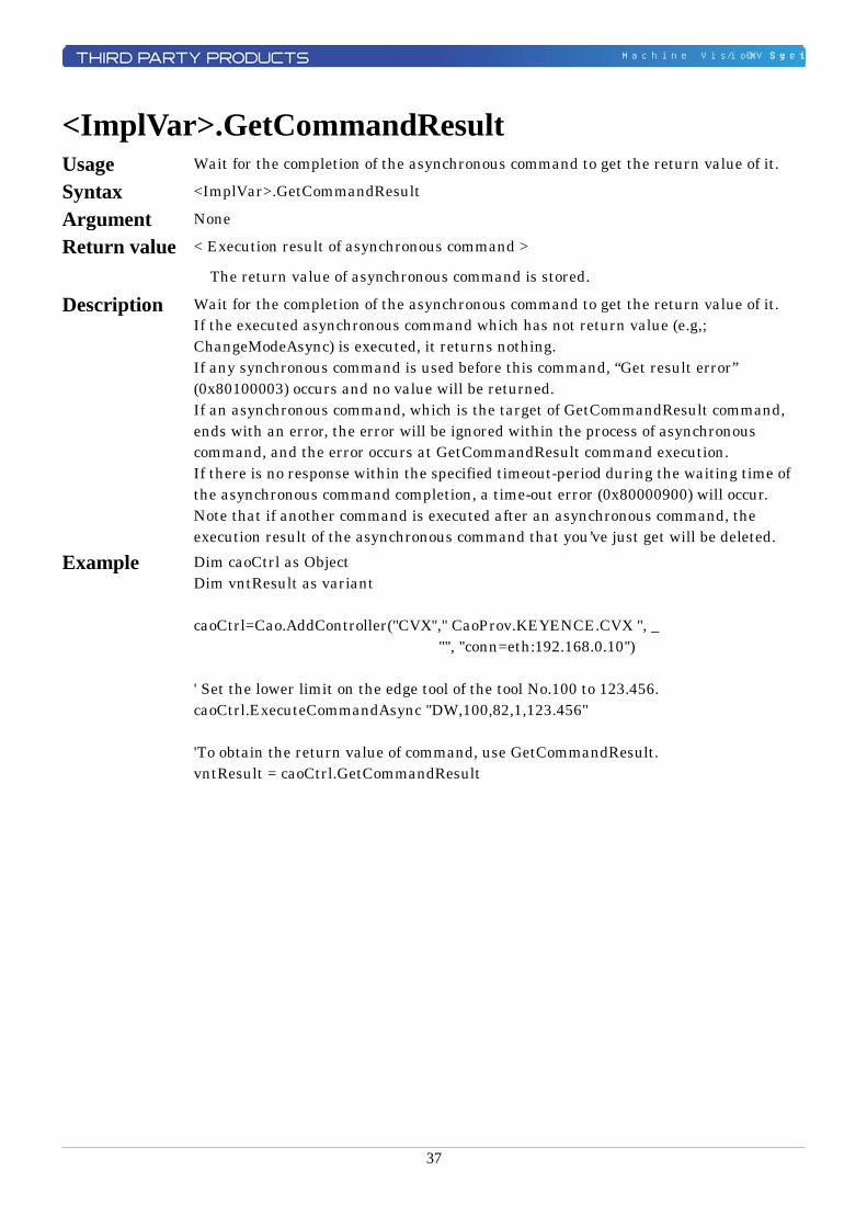
<ImplVar>.GetCommandResult Usage Wait for the completion of the asynchronous command to get the return value of it.
Syntax <ImplVar>.GetCommandResult
Argument None
Return value < Execution result of asynchronous command >
The return value of asynchronous command is stored.
Description Wait for the completion of the asynchronous command to get the return value of it. If the executed asynchronous command which has not return value (e.g,; ChangeModeAsync) is executed, it returns nothing. If any synchronous command is used before this command, “Get result error” (0x80100003) occurs and no value will be returned. If an asynchronous command, which is the target of GetCommandResult command, ends with an error, the error will be ignored within the process of asynchronous command, and the error occurs at GetCommandResult command execution. If there is no response within the specified timeout-period during the waiting time of the asynchronous command completion, a time-out error (0x80000900) will occur. Note that if another command is executed after an asynchronous command, the execution result of the asynchronous command that you’ve just get will be deleted.
Example Dim caoCtrl as Object Dim vntResult as variant caoCtrl=Cao.AddController("CVX"," CaoProv.KEYENCE.CVX ", _ "", "conn=eth:192.168.0.10") ' Set the lower limit on the edge tool of the tool No.100 to 123.456. caoCtrl.ExecuteCommandAsync "DW,100,82,1,123.456" 'To obtain the return value of command, use GetCommandResult. vntResult = caoCtrl.GetCommandResult
38
Machine Vision System / CV-X Series
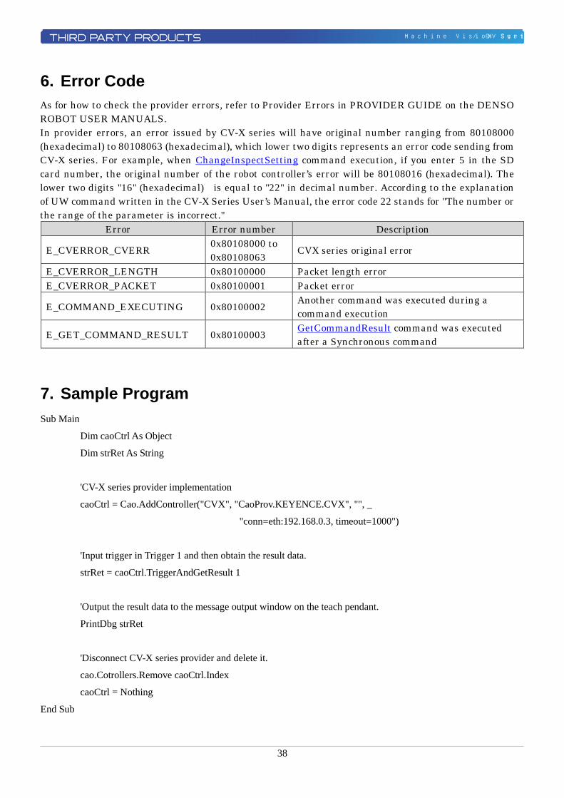
6. Error Code As for how to check the provider errors, refer to Provider Errors in PROVIDER GUIDE on the DENSO ROBOT USER MANUALS. In provider errors, an error issued by CV-X series will have original number ranging from 80108000 (hexadecimal) to 80108063 (hexadecimal), which lower two digits represents an error code sending from CV-X series. For example, when ChangeInspectSetting command execution, if you enter 5 in the SD card number, the original number of the robot controller’s error will be 80108016 (hexadecimal). The lower two digits "16" (hexadecimal) is equal to "22" in decimal number. According to the explanation of UW command written in the CV-X Series User’s Manual, the error code 22 stands for "The number or the range of the parameter is incorrect."
Error Error number Description
E_CVERROR_CVERR 0x80108000 to 0x80108063 CVX series original error
E_CVERROR_LENGTH 0x80100000 Packet length error E_CVERROR_PACKET 0x80100001 Packet error
E_COMMAND_EXECUTING 0x80100002 Another command was executed during a command execution
E_GET_COMMAND_RESULT 0x80100003 GetCommandResult command was executed after a Synchronous command
7. Sample Program Sub Main
Dim caoCtrl As Object
Dim strRet As String
'CV-X series provider implementation
caoCtrl = Cao.AddController("CVX", "CaoProv.KEYENCE.CVX", "", _
"conn=eth:192.168.0.3, timeout=1000")
'Input trigger in Trigger 1 and then obtain the result data.
strRet = caoCtrl.TriggerAndGetResult 1
'Output the result data to the message output window on the teach pendant.
PrintDbg strRet
'Disconnect CV-X series provider and delete it.
cao.Cotrollers.Remove caoCtrl.Index
caoCtrl = Nothing
End Sub
39
Machine Vision System / CV-X Series
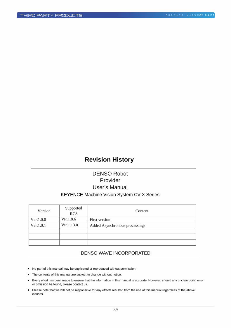
Revision History
DENSO Robot Provider
User’s Manual KEYENCE Machine Vision System CV-X Series
Version Supported
RC8 Content
Ver.1.0.0 Ver.1.8.6 First version Ver.1.0.1 Ver.1.13.0 Added Asynchronous processings
DENSO WAVE INCORPORATED
● No part of this manual may be duplicated or reproduced without permission.
● The contents of this manual are subject to change without notice.
● Every effort has been made to ensure that the information in this manual is accurate. However, should any unclear point, error or omission be found, please contact us.
● Please note that we will not be responsible for any effects resulted from the use of this manual regardless of the above clauses.

40
Machine Vision System / CV-X Series