Embed Size (px)
Citation preview
© 2001 MIT PSDAM AND PERG LABS
KINEMATIC COUPLINGS
The good, the bad, the ugly….
© 2001 MIT PSDAM AND PERG LABS
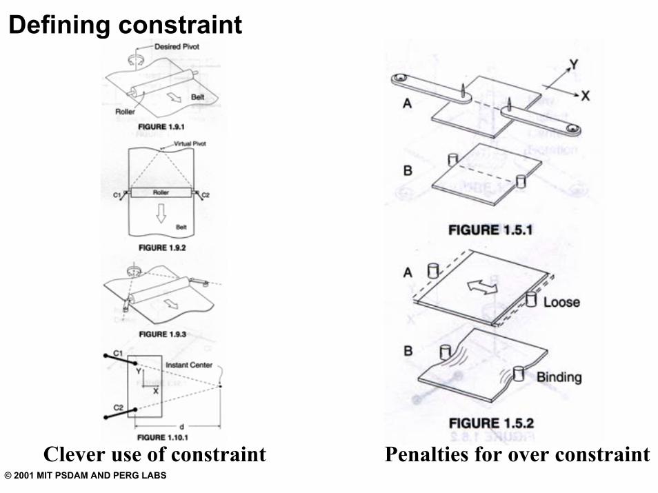
Defining constraint
Penalties for over constraintClever use of constraint
© 2001 MIT PSDAM AND PERG LABS
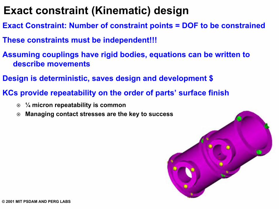
Exact constraint (Kinematic) designExact Constraint: Number of constraint points = DOF to be constrained
These constraints must be independent!!!
Assuming couplings have rigid bodies, equations can be written to describe movements
Design is deterministic, saves design and development $
KCs provide repeatability on the order of parts’ surface finish¼ micron repeatability is commonManaging contact stresses are the key to success
© 2001 MIT PSDAM AND PERG LABS
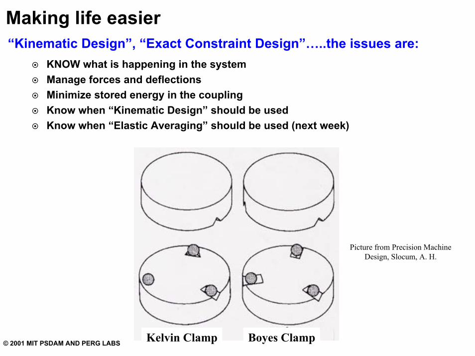
Making life easier“Kinematic Design”, “Exact Constraint Design”…..the issues are:
KNOW what is happening in the systemManage forces and deflectionsMinimize stored energy in the couplingKnow when “Kinematic Design” should be usedKnow when “Elastic Averaging” should be used (next week)
Boyes ClampKelvin Clamp
Picture from Precision Machine Design, Slocum, A. H.
© 2001 MIT PSDAM AND PERG LABS
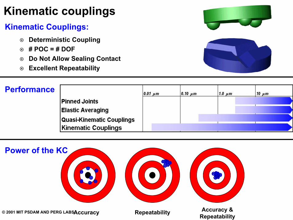
Kinematic couplingsKinematic Couplings:
Deterministic Coupling# POC = # DOFDo Not Allow Sealing ContactExcellent Repeatability
Performance
Power of the KC
Accuracy Repeatability Accuracy & Repeatability
© 2001 MIT PSDAM AND PERG LABS
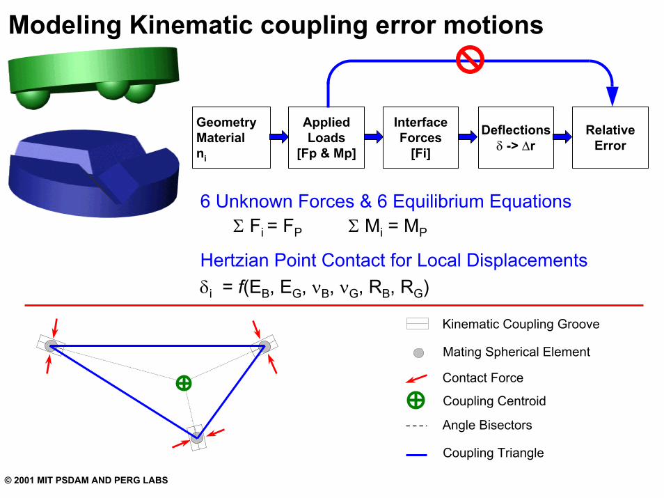
Modeling Kinematic coupling error motions
InterfaceForces
[Fi]
AppliedLoads
[Fp & Mp]
Deflectionsδ -> ∆r
RelativeError
GeometryMaterialni
Σ Fi = FP Σ Mi = MP
6 Unknown Forces & 6 Equilibrium Equations
Hertzian Point Contact for Local Displacementsδi = f(EB, EG, νB, νG, RB, RG)
Kinematic Coupling Groove
Mating Spherical Element
Contact Force
Coupling Centroid
Angle Bisectors
Coupling Triangle
© 2001 MIT PSDAM AND PERG LABS
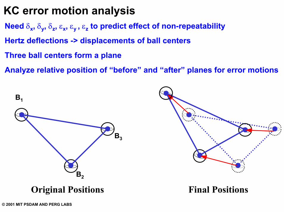
KC error motion analysisNeed δx, δy, δz, εx, εy , εz to predict effect of non-repeatability
Hertz deflections -> displacements of ball centers
Three ball centers form a plane
Analyze relative position of “before” and “after” planes for error motions
B1
B3
B2
Original Positions Final Positions
© 2001 MIT PSDAM AND PERG LABS
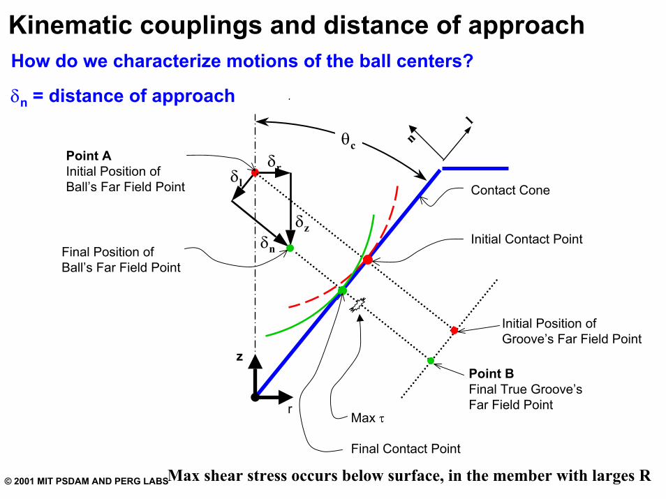
Kinematic couplings and distance of approachHow do we characterize motions of the ball centers?
δn = distance of approach
δr
δzδn
δl
Point AInitial Position ofBall’s Far Field Point
Final Position ofBall’s Far Field Point
r
z
l
n
Point BFinal True Groove’sFar Field Point
Initial Position ofGroove’s Far Field Point
Initial Contact Point
Final Contact Point
Max τ
Contact Cone
θc
Max shear stress occurs below surface, in the member with larges R
© 2001 MIT PSDAM AND PERG LABS
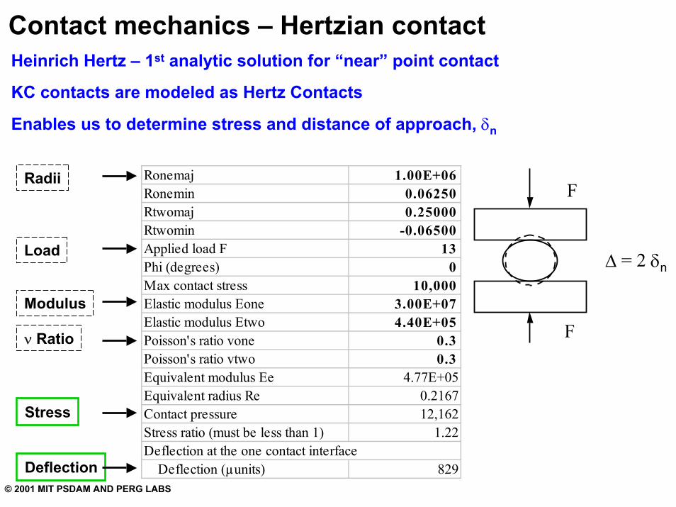
Contact mechanics – Hertzian contactHeinrich Hertz – 1st analytic solution for “near” point contact
KC contacts are modeled as Hertz Contacts
Enables us to determine stress and distance of approach, δn
Ronemaj 1.00E+06Ronemin 0.06250Rtwomaj 0.25000Rtwomin -0.06500Applied load F 13Phi (degrees) 0Max contact stress 10,000Elastic modulus Eone 3.00E+07Elastic modulus Etwo 4.40E+05Poisson's ratio vone 0.3Poisson's ratio vtwo 0.3Equivalent modulus Ee 4.77E+05Equivalent radius Re 0.2167Contact pressure 12,162Stress ratio (must be less than 1) 1.22Deflection at the one contact interface Deflection (µunits) 829
F
F
∆ = 2 δn
Radii
Load
Modulus
ν Ratio
Stress
Deflection
© 2001 MIT PSDAM AND PERG LABS
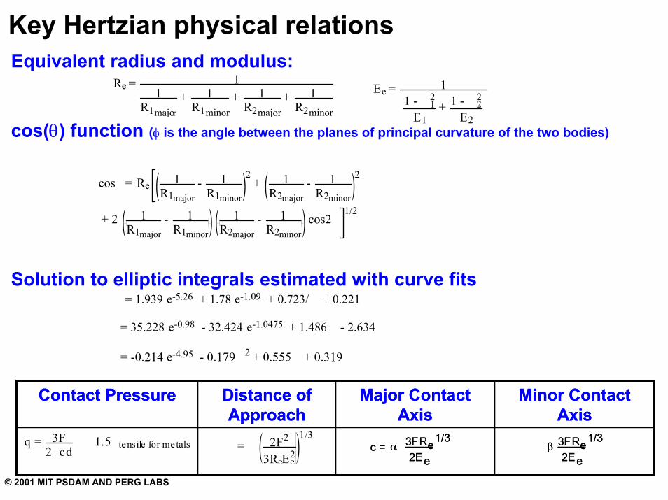
Key Hertzian physical relationsEquivalent radius and modulus:
cos(θ) function (φ is the angle between the planes of principal curvature of the two bodies)
Solution to elliptic integrals estimated with curve fits
cos = R e 1 R 1 major
- 1 R 1 minor
2 + 1
R 2 major - 1
R 2 minor
2
+ 2 R 1 major
- R 1 minor
R 2 major
- R 2 minor
cos2 1/2
R e = 1 1
R 1 major + 1
R 1 minor + 1
R 2 major + 1
R 2 minor
E e = 1
1 - 1 2
E 1 + 1 - 2
2
E 2
= 1.939 e -5.26 + 1.78 e -1.09 + 0.723/ + 0.221
= 35.228 e -0.98 - 32.424 e -1.0475 + 1.486 - 2.634
= -0.214 e -4.95 - 0.179 2 + 0.555 + 0.319
q = 3F2 cd
1.5 tensile for metals = 2 F 2
3 R e E e 2
1/3
Minor Contact Axis
Major Contact Axis
Distance of Approach
Contact Pressure Minor Contact Axis
Major Contact Axis
Distance of Approach
Contact Pressure
β 3FR e 2Ee
1/3 β 3FR e
2Ee
1/3 c = α 3FR e
2Ee
1/3 c = α 3FR e
2Ee
1/3
1 1 1 1
© 2001 MIT PSDAM AND PERG LABS
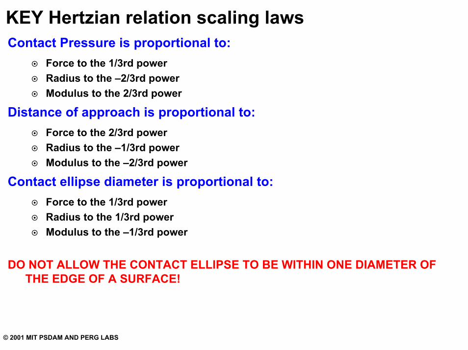
KEY Hertzian relation scaling lawsContact Pressure is proportional to:
Force to the 1/3rd powerRadius to the –2/3rd powerModulus to the 2/3rd power
Distance of approach is proportional to:Force to the 2/3rd powerRadius to the –1/3rd powerModulus to the –2/3rd power
Contact ellipse diameter is proportional to:Force to the 1/3rd powerRadius to the 1/3rd powerModulus to the –1/3rd power
DO NOT ALLOW THE CONTACT ELLIPSE TO BE WITHIN ONE DIAMETER OF THE EDGE OF A SURFACE!
© 2001 MIT PSDAM AND PERG LABS
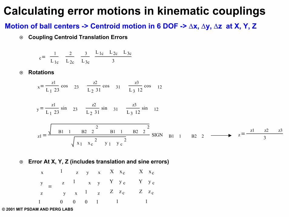
Calculating error motions in kinematic couplingsMotion of ball centers -> Centroid motion in 6 DOF -> ∆x, ∆y, ∆z at X, Y, Z
Coupling Centroid Translation Errors
Rotations
Error At X, Y, Z (includes translation and sine errors)
c 1
L 1c
2
L 2c
3
L 3c
L 1c L 2c L 3c
3
x z1
L 1 23 cos 23
z2
L 2 31 cos 31
z3
L 3 12 cos 12
y z1
L 1 23 sin 23
z2
L 2 31 sin 31
z3
L 3 12 sin 12
z1 B1 1 B2 2 2
B1 1 B2 2 2
x1 xc 2 y 1 y c 2 SIGN B1 1 B2 2 z
z1 z2 z3
3
x
y
z
1
1
z
y
0
z
1
x
0
y
x
1
0
x
y
z
1
X xc
Y y c
Z z c
1
X xc
Y y c
Z z c
1
© 2001 MIT PSDAM AND PERG LABS
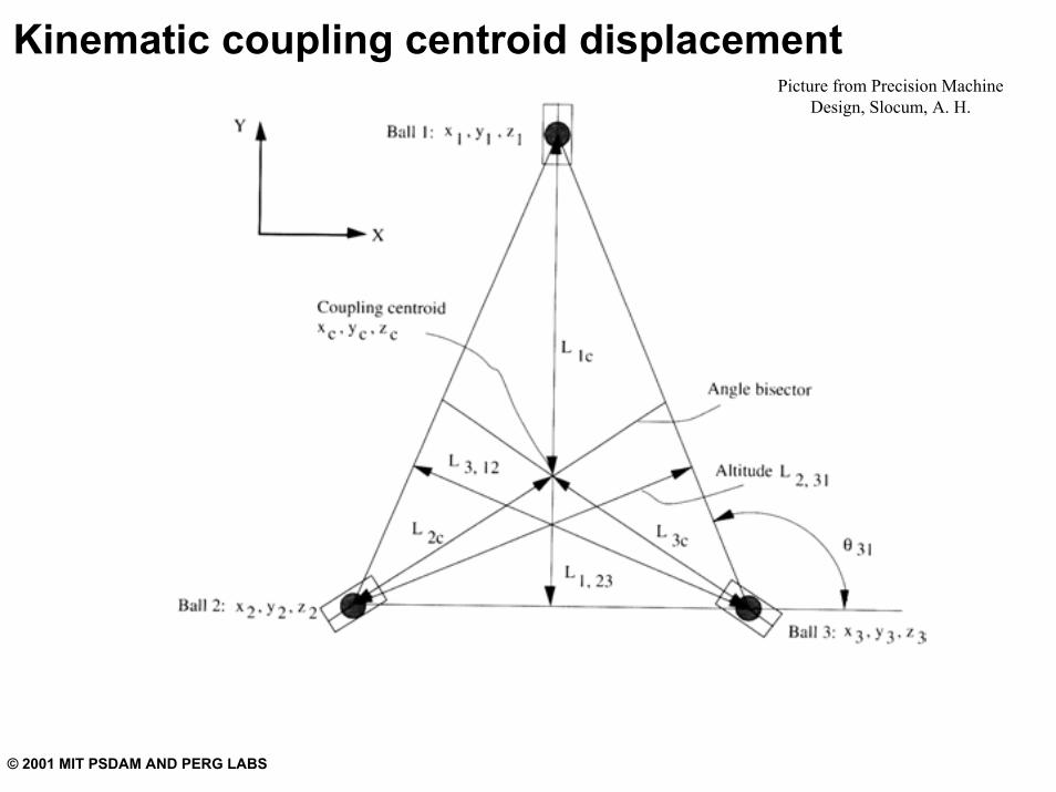
Kinematic coupling centroid displacementPicture from Precision Machine
Design, Slocum, A. H.
© 2001 MIT PSDAM AND PERG LABS
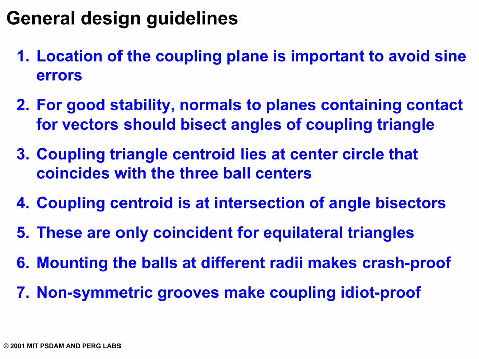
General design guidelines
1. Location of the coupling plane is important to avoid sine errors
2. For good stability, normals to planes containing contact for vectors should bisect angles of coupling triangle
3. Coupling triangle centroid lies at center circle that coincides with the three ball centers
4. Coupling centroid is at intersection of angle bisectors
5. These are only coincident for equilateral triangles
6. Mounting the balls at different radii makes crash-proof
7. Non-symmetric grooves make coupling idiot-proof
© 2001 MIT PSDAM AND PERG LABS
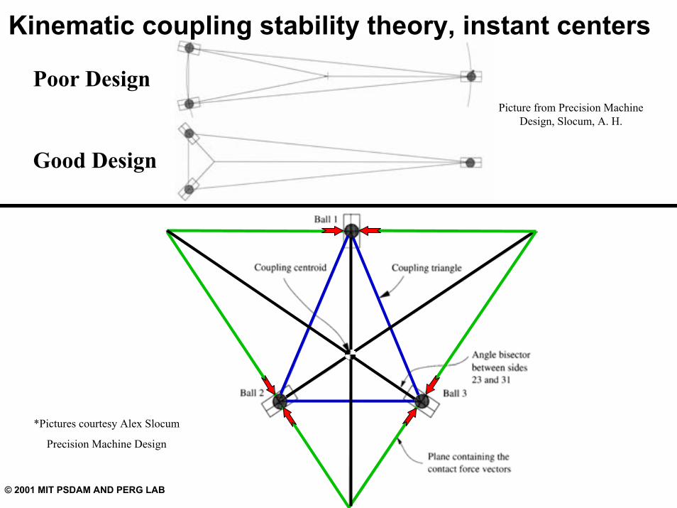
Kinematic coupling stability theory, instant centers
Poor Design
Good Design
Picture from Precision Machine Design, Slocum, A. H.
*Pictures courtesy Alex Slocum
Precision Machine Design
© 2001 MIT PSDAM AND PERG LABS
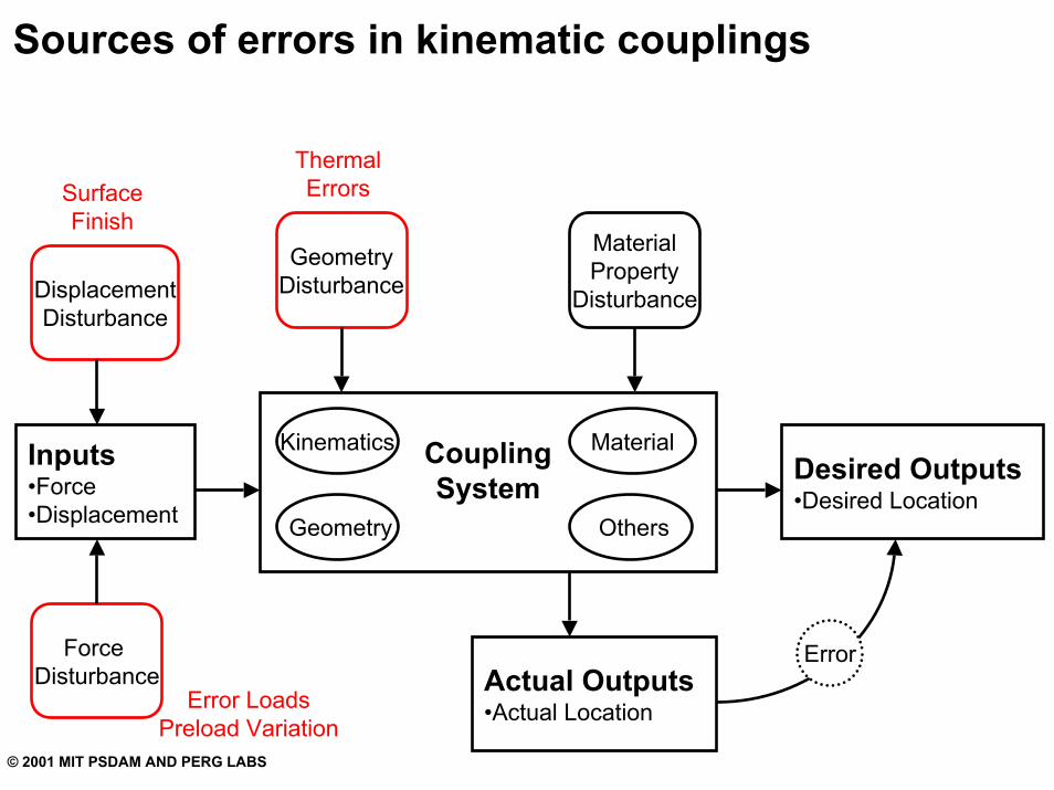
Sources of errors in kinematic couplings
ThermalErrorsSurface
FinishMaterialProperty
Disturbance
GeometryDisturbanceDisplacement
Disturbance
CouplingSystem
Force Disturbance
Desired Outputs•Desired Location
Error
Kinematics MaterialInputs•Force•Displacement Geometry Others
Actual Outputs•Actual LocationError Loads
Preload Variation
© 2001 MIT PSDAM AND PERG LABS
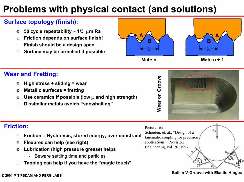
Problems with physical contact (and solutions)Surface topology (finish):
50 cycle repeatability ~ 1/3 µm RaFriction depends on surface finish!Finish should be a design specSurface may be brinelled if possible
Wear and Fretting:High stress + sliding = wearMetallic surfaces = frettingUse ceramics if possible (low µ and high strength)Dissimilar metals avoids “snowballing”
Friction:Friction = Hysteresis, stored energy, over constraintFlexures can help (see right)Lubrication (high pressure grease) helps
- Beware settling time and particlesTapping can help if you have the “magic touch”
BA
λB
A
λ
Ball in V-Groove with Elastic Hinges
Mate n Mate n + 1
Wea
r on
Gro
ove
Picture from:Schouten, et. al., “Design of a kinematic coupling for precision applications”, Precision Engineering, vol. 20, 1997.
© 2001 MIT PSDAM AND PERG LABS
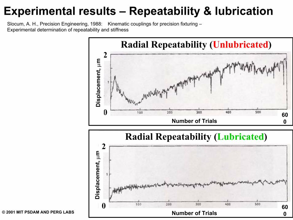
Experimental results – Repeatability & lubricationSlocum, A. H., Precision Engineering, 1988: Kinematic couplings for precision fixturing –Experimental determination of repeatability and stiffness
Number of Trials
Radial Repeatability (Unlubricated)2
0
Dis
plac
emen
t, µm
600
Number of Trials
Radial Repeatability (Lubricated)
600
Dis
plac
emen
t, µm
2
0
© 2001 MIT PSDAM AND PERG LABS
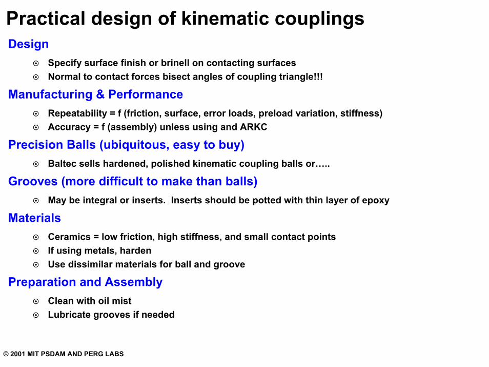
Practical design of kinematic couplingsDesign
Specify surface finish or brinell on contacting surfacesNormal to contact forces bisect angles of coupling triangle!!!
Manufacturing & PerformanceRepeatability = f (friction, surface, error loads, preload variation, stiffness)Accuracy = f (assembly) unless using and ARKC
Precision Balls (ubiquitous, easy to buy)Baltec sells hardened, polished kinematic coupling balls or…..
Grooves (more difficult to make than balls)May be integral or inserts. Inserts should be potted with thin layer of epoxy
MaterialsCeramics = low friction, high stiffness, and small contact pointsIf using metals, hardenUse dissimilar materials for ball and groove
Preparation and AssemblyClean with oil mistLubricate grooves if needed
© 2001 MIT PSDAM AND PERG LABS
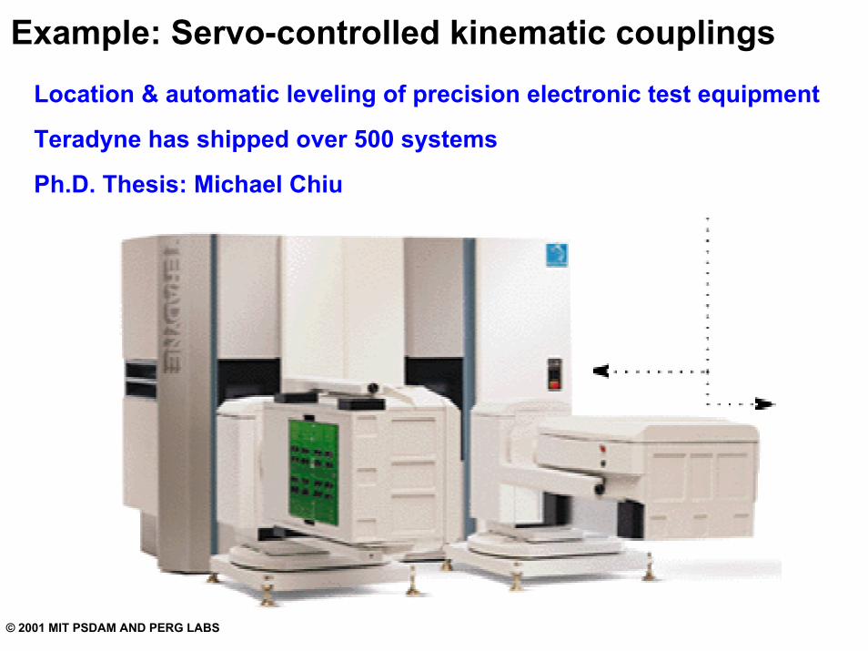
Example: Servo-controlled kinematic couplingsLocation & automatic leveling of precision electronic test equipment
Teradyne has shipped over 500 systems
Ph.D. Thesis: Michael Chiu
© 2001 MIT PSDAM AND PERG LABS
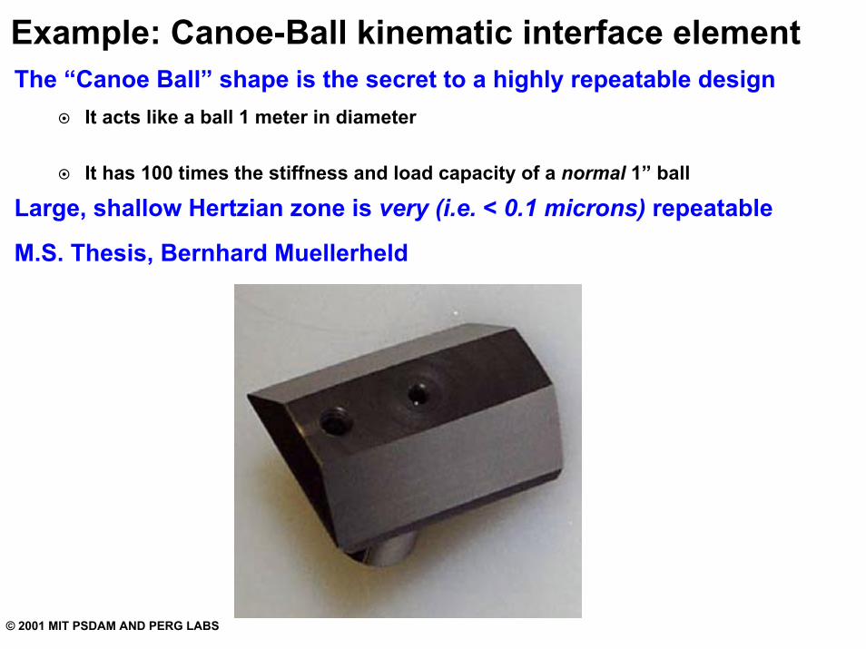
Example: Canoe-Ball kinematic interface elementThe “Canoe Ball” shape is the secret to a highly repeatable design
It acts like a ball 1 meter in diameter
It has 100 times the stiffness and load capacity of a normal 1” ball
Large, shallow Hertzian zone is very (i.e. < 0.1 microns) repeatable
M.S. Thesis, Bernhard Muellerheld
© 2001 MIT PSDAM AND PERG LABS
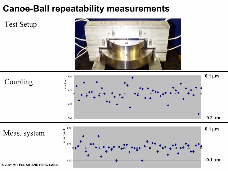
Canoe-Ball repeatability measurementsTest Setup
-0.20
-0.10
0.00
0.10
0 5 10 15 20 25 30 35 40 45 50
erro
r [ µ
m ]
0.1 µm
-0.2 µm
Coupling
-0.10
0.00
0.10
0 5 10 15 20 25 30 35 40 45 50
erro
r [
µm
] 0.1 µm
-0.1 µm
Meas. system
© 2001 MIT PSDAM AND PERG LABS
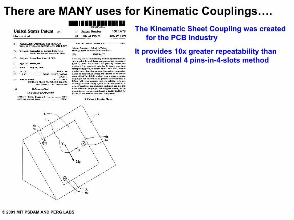
There are MANY uses for Kinematic Couplings….The Kinematic Sheet Coupling was created
for the PCB industry
It provides 10x greater repeatability than traditional 4 pins-in-4-slots method